
Related Manuals for Axia Fusion


Summary of Contents for Axia Fusion
- Page 1 Fusion Console Installation & User’s Guide Includes StudioEngine and PowerStation Manual Rev 4 (3.2) - Nov 2017 p/n 1490-00109-005...
- Page 2 If the equipment is used in a manner not specified by the manufacturer, the protection provided by the equipment may be impaired. © 2017 Axia Audio - Rev 3.2...
- Page 3 Gerät nicht auf einem Teppich, Poster oder andere Materialien welche die Lüftungsöffnungen beeinträchtigen könnten. Wird das Gerät anders als in der, vom Hersteller angegebenen Weise verwendet, kann der, durch das Gerät gegebene Schutz beeinträchtigt werden. © 2017 Axia Audio - Rev 3.2...
- Page 4 This device complies with the requirements of the EEC council directives: • 93/68/EEC (CE MARKING) • 73/23/EEC (SAFETY – LOW VOLTAGE DIRECTIVE) • 89/336/EEC (ELECTROMAGNETIC COMPATIBILITY) Conformity is declared to those standards: EN50081-1, EN50082-1. © 2017 Axia Audio - Rev 3.2...
- Page 5 Fusion Manual © 2014-2017 TLS Corp. Published by Axia Audio/TLS Corp. All rights reserved. TRADEMARKS Axia Audio and the Axia and Fusion logos are trademarks of TLS Corp. All other trademarks are the property of their respective holders. NOTICE All versions, claims of compatibility, trademarks, etc. of hardware and software products not made by Axia Audio which are mentioned in this manual or accompanying material are informational only.
- Page 6 • All other questions, please email inquiry@telosalliance.com. VIA WORLD WIDE WEB: The Axia Audio web site has a variety of information which may be useful for product selection and support. The url is telosalliance.com. REGISTER YOUR PRODUCT Did you know that all Telos Alliance products come with a 5-Year Warranty? Take a moment to activate your coverage online at http://telosalliance.com/product-registration/ .
-
Page 7: Table Of Contents
Color Indication ....Fusion Manual ..... v Loudness Range . - Page 8 Chapter 5 Working With Phones ... . 67 GPIO Operator’s Microphone Logic ..Phone Setup Choices ....67 GPIO Control Room Guest Microphone Logic .
-
Page 9: War Of The Waves
Axia Audio is a driving force behind the AES67 AoIP standard, and its networked AoIP radio consoles, audio interfaces, networked intercom, and software products continue to move AoIP adoption forward and help broadcasters streamline operations with cohesive, smart, and feature-rich AoIP ecosystems. - Page 10 Intentionally Left Blank...
-
Page 11: Quickstart #1
Livewire NIC To begin, connect a 1080p widescreen computer monitor to the DVI port on the Axia StudioEngine’s rear panel. Also connect the RJ-45 port marked with the Livewire logo to a port on your AoIP network’s local switch using a CAT-6 Ethernet cable. - Page 12 Console power connection Connect the Power cable from your Fusion console to the marked power supply port on the rear of your Fusion Power Supply, and then connect the Fusion Power Supply to AC mains using the IEC cable supplied.
- Page 13 5. Select the check mark to the right of the IP address to accept. 6. Repeat this process for the Netmask and Gateway fields, as needed. 7. Select “Console” and change the option to “Fusion”. 8. Select “OK.” After selecting OK, respond affirmative to the following notice to reboot the engine with its new settings.
- Page 14 3. Enter the value 1 into the Console count field and click the Apply Console Count button. 4. The software will display a list of the consoles found on your network. Select your Fusion from the drop-down list. 5. Click the Apply IP button to set the IP address of your Fusion, and to link it with the StudioEngine.
-
Page 15: Creating Your First Source
Creating Your First Source And Assigning It To A Fader You’ll use your Web browser and the Fusion interface to create your first audio source in just a few fast steps. 1. In the side menu under the Console heading, select Sources, then click the Create new source profile button. - Page 16 3. Press the browse button to the right of the Primary source field; a pop-up window will appear with a list of sources available on your Axia network. Select the desired source from the list, and click the OK button.
-
Page 17: Setting Up And Testing Control Room Monitor Channels
2. Enter the planned Channel Numbers for the StudioEngine outputs (Livewire Sources). Click the Apply button. 3. On your Fusion console, press the Options knob found at the top of any fader strip. Your video monitor’s center section will change, showing the Channel Options display. - Page 18 Now, sit back and enjoy some music as you read the remainder of this manual, or continue to explore the Configuration pages of your StudioEngine; the details of these options can be found in the Configuration section of this manual. © 2017 Axia Audio - Rev 3.2...
-
Page 19: Quickstart #2
USB Port DVI Monitor connector To begin, connect a 1080p widescreen computer monitor to the DVI port on the Axia PowerStation Main rear panel. Connect a USB keyboard to the USB port on the rear of your PowerStation Main. © 2017 Axia Audio - Rev 3.2... - Page 20 Next, connect one end of the 6-pin Molex power cable supplied with your PowerStation to the Power connection on the board located beneath the overbridge of the Fusion surface. © 2017 Axia Audio - Rev 3.2...
- Page 21 Connect the other end to the Molex connector marked SURFACE on the rear of your PowerStation. Now, Connect a network patch cable from the board under the Fusion’s overbridge to any available port on the PowerStation’s switch. The next step requires a Web browser on a PC connected to any Ethernet port on your PowerStation’s switch section.
- Page 22 5. Click the Apply IP button to set the IP address of your Fusion, and to link it with the PowerStation. Your Fusion console is now connected! Notice that the displays above each fader strip read INACTIVE. One more fast step will complete the setup process.
-
Page 23: Creating Your First Source
Creating Your First Source And Assigning It To A Fader You’ll use your Web browser and the Fusion interface to create your first audio source in just a few fast steps. 1. In the side menu under the Console heading, select Sources, then click the Create new source profile button. -
Page 24: Setting Up And Testing Control Room Monitor Channels
3. In the side menu, select the Destinations link under the I/O subsystem main heading. You’ll be prompted for a Username and Password. Enter the following values: • Username = user • Password = <leave blank> © 2017 Axia Audio - Rev 3.2... - Page 25 Browse button next to the “Channel” field. From the popup, select the CR Monitor source from the PowerStation. 5. On your Fusion console, press the Options knob found at the top of any fader strip. Your video monitor’s center section will change, showing the Channel Options display.
- Page 26 7. You’ll now see a list of your available Sources (in this case, just one: the one we just configured. If you already have an Axia network deployed, you may see a larger list.) 8. Rotate the Options encoder to highlight the source you just created. Press the encoder to select the high- lighted source.
-
Page 27: Chapter 1: Fusion Anatomy
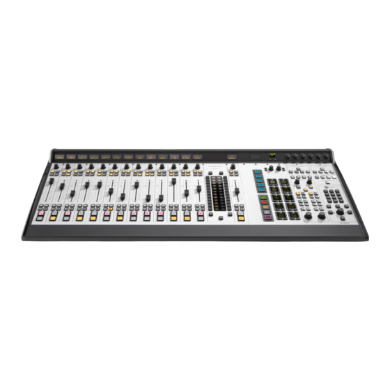
Chapter 1: Fusion Anatomy The Fusion modular control surface is more than a just console — it is a complete studio system, with various components that serve different functions. This chapter gives an overview of the different components to help familiarize you;. The following chapters will build on this familiarity as we dive deeper into Fusion’s features and capabilities. - Page 28 1080p resolution. Below the video connector are two RJ45 ports. The Livewire port is used for connection to the Axia network (the second port is reserved for future use). The two USB ports are also for future use, or possible service functionality.
- Page 29 The PowerStation MAIN front panel has no user interface, but does have a number of useful status indicators: • The Axia logo, glowing blue, indicates that power is present in the internal power supply (after redundant- power-supply isolation, if a PowerStation AUX with redundant power is connected) •...
- Page 30 Two (2) XLR microphone inputs • Four (4) RJ45 stereo analog inputs • Two (2) RJ45 AES digital audios inputs • Six (6) RJ45 stereo analog outputs • Two (2) RJ45 AES digital audio outputs © 2017 Axia Audio - Rev 3.2...
-
Page 31: Can4Eth
6-pin Molex connector to supply the console with 48v power. CAN4ETH Underneath the overbridge of the Fusion surface is the board that links the console modules to the main CPU of either your StudioEngine or PowerStation. The surface uses CANBus (Control Area Network) as a common interface for modules, then links the surface’s mixing modules to its associated CPU via an Ethernet link. -
Page 32: Fusion Power Supply
AC mains power input. Console Modules The Fusion surface is a mixing desk of modular design. The composition of the surface consists of a console frame (which is available in multiple sizes), and an assortment of modules to suit your operational requirements. -
Page 33: Chapter 2: Configuration Basics
Chapter 2: Configuration Basics In this chapter, we look past the Quickstart to some of the powerful tools available to you with your Fusion console — such as choosing and modifying Source Profiles, Show Profiles, and other essentials. Let’s dive in! Working With Profiles A standard console configuration step is defining the sources that will be used on the console. - Page 34 With that, connect a computer to your Fusion’s StudioEngine or PowerStation, type its IP address into your Web browser, and follow along. To get started, select the Sources link, as shown here: Once you’ve done this, you’ll see any sources that have already been configured, as well as to “Create new source profile”...
-
Page 35: Create The Operator's Mic Source Profile
Create the Operator’s Mic Source Profile The Operator’s mic is intended for the operator of the Fusion console, so let’s create this first. Click Create new source profile. You’ll see the following screen on your computer: Select “Operator” from the Source type drop-down list. In the Source name field, type a useful name, like “Host”... - Page 36 Control Room (CR) monitors when the mic is open, as well as being the default source for any Talkback commands that are engaged. Therefore, any additional Microphone source should be one of the other microphone source types. © 2017 Axia Audio - Rev 3.2...
-
Page 37: Create A Guest Mic Source Profile
The “CR guest” source type is intended for microphones located at guest positions within the same control room as the Fusion surface. The built-in logic functions will mute the CR monitors when the source is turned on, and provide GPIO logic for an optional Guest Control Panel that uses GPIO to remotely control Channel ON/OFF/ MUTE and Talkback functions. -
Page 38: Other Helpful Options: Knob Function
CR producer is intended for a Show Producer’s mic loated in the same studio as the mixing console, so its GPIO logic functions mute the CR monitors, and specialized GPIO functionality permits the producer to talk (using Backfeeds, Axia’s name for internal foldback, or IFB) to any source with a Backfeed that is assigned to the Preview (cue) channel. -
Page 39: Create A Cd Player Source (Line Source Type)
Now click the OK button at the bottom of the screen; your CD player is configured and ready to be assigned to a fader. © 2017 Axia Audio - Rev 3.2... - Page 40 “Ready” indication. If it doesn’t, your operators may think the OFF lamp is broken because it never illuminates! © 2017 Axia Audio - Rev 3.2...
-
Page 41: Create A Telephone Source (Phone Source Type)
Create a Telephone Source (Phone Source Type) Putting phones on-air is one of the basic operations of the modern studio. Fusion’s Phone Source Type helps ease the task of handling outboard phone hybrids. © 2017 Axia Audio - Rev 3.2... - Page 42 First, select “Phone” from the Source Type dropdown, and some phone-specific options will appear. In the Source Name field, type the name you’d like to display on the Fusion’s OLED channel display. Now, to define the Phone controls. Select from one of the following options that best suits your studio’s phone gear: •...
-
Page 43: Advanced Stuff: A Codec Source With Custom Backfeed
Source Profile controls. The final step is to define how you want to handle mix-minus. Fusion (and all Axia consoles) automatically generates mix-minus (N-1, “clean feed”) for each phone caller taken to air. To configure this, you’ll scroll to the Default Backfeed Options box and select the desired audio mix from the Feed to Source dropdown. - Page 44 M-1 Mono Sum/Left/Right sends a mix-minus of the stereo Program output, minus the source, as either a summed Mono signal, or as the Left or Right channel of the stereo Program output, minus the source. © 2017 Axia Audio - Rev 3.2...
- Page 45 Note: Record Mode is a special “macro” mode that helps talent record audio for later use with a single press of the Fusion console’s “Record” key, located on the Monitor Module. We’ll cover use of this function in later chapters.
- Page 46 • Phone. Fusion has an off-line Phone bus that is actually a special variant of PGM4. The Phone bus is mono-sum, prefader and pre-on/off to allow speaker-phone style operation thru the Operator’s mic. Select- ing Phone feeds the Phone bus, minus the source, so that the listener can hear other Phone callers who are waiting in the air queue.
-
Page 47: Show Profiles
– that instantly recall your saved configuration when loaded. How to Create A Show Profile The easiest way to create a Show Profile is to set up your Fusion console for a show, then save a Show Profile for it by taking a “snapshot.” •... -
Page 48: Other Configuration Options
In the column of links on the left hand size is the customize option. From this link you can configure a few global options. User Logo: By default the Fusion video output will show the Fusion logo, but you are free to upload your own logo which fits within the designated resolution of 331x42px. Clock: The Fusion display output has time information and this can be configured in various ways. -
Page 49: Enable Loudness Meter
The relative loudness option changes the numerical presentation so that the number is in reference to the target. A value of 0 LU indicates the target value is achieved. Lower than target value will be negative (-) LU while positive (+) LU indicates higher than target. © 2017 Axia Audio - Rev 3.2... -
Page 50: Color Indication
ON buttons can act to enable the fader to control the state of the channel or not. The default Arm indication is a blink operation. So may prefer a solid illuminated button. Confidence metering options allow for enabling or disabling the meter presentation on the surface. © 2017 Axia Audio - Rev 3.2... -
Page 51: Sound4 Remote Control
The Omnia Voco8 is a powerful microphone processor with many option and controls. For easy recall of the presets during a show in progress, the Fusion console provides an interface to control the Voco 8 in Live mode. To setup, enter in the Server IP and the appropriate login and password. - Page 52 Intentionally Left Blank...
-
Page 53: Chapter 3: Operation
Chapter 3: Operation Fusion was designed with speed in mind. On-air studios are fast-paced operations, and our design goal is for every control, display and interface to enhance your Operator’s speed and accuracy. Because different people work differently, we’ve made it possible to access some functions in multiple ways. -
Page 54: Main Display
Main Display This is the main Fusion display screen. 99% of the time, this is what you’ll see on your Studio display. 1. Main Meters. There are 6 bargraph-style meters on-screen at all times. By with phase indication at top are default, they meter the PGM-1 –... - Page 55 7. Profile Window. Displays the name of the active Show Profile. 8. Loudness Meter. Will be displayed under the Show Profile window if enabled. 9. Day/Date/Time Displays. Shows the current date and time in digital format. © 2017 Axia Audio - Rev 3.2...
-
Page 56: Basic Channel Controls
Basic Channel Controls Here’s the 4-Fader (S) Module, the basic building block of any Fusion console. The controls should be familiar to any radio pro: Channel Display. This window displays the audio source assigned to the fader, plus confi- dence meters for incoming audio. If the operator... -
Page 57: Expert Monitor Module Controls
Multi-Function Knobs. When advanced controls are active, the center clock in Fusion’s display changes to indicate the active function, and the action of each knob when pressed or rotated. - Page 58 » up to 4 additional onscreen meters, whose sources preset by the Engineer. Sends & Returns key lets operator adjust the master volume of Fusion’s four Aux Send buses, and » volume and Program bus assignments of the two Aux Return buses. Press once to work with Sends, twice for Returns.
-
Page 59: Standard Monitor Module Controls
Pressing once invokes Record Mode; a second press returns the console to its previous state. 5. Timer controls. Affects options of the Count Down and Count Up onscreen timers. © 2017 Axia Audio - Rev 3.2... - Page 60 » The Preview knob adjusts the volume of the Preview (cue) speaker. » The Preview to HP key turns Preview To Headphones on and off. Rotating the Headphones knob varies the volume of the studio Headphone feed. » © 2017 Axia Audio - Rev 3.2...
-
Page 61: Call Controller + 2-Fader Phone Module
Telos phone system. 1. Xfer Call key lets the board operator transfer a call from the Fusion Phone module to a local handset for off-console control or off-air conversations. 2. Block All key “busies out” all inactive phone lines, blocking incoming calls in preparation for on-air con- testing. -
Page 62: Ip Intercom Module - 20-Station
IP Intercom Module – 20-Station This module provides on-console integration with the Axia IP Inter- com system, and gives access to 20 preprogrammed intercom stations, plus dial-up access to stations systemwide that have not been pro- grammed to one of the speed-dial stations. The Operator’s mic is used as the local talk source;... -
Page 63: Ip Intercom Module - 10-Station Filmcap
What’s Next In the next chapter, we’ll learn about the use of Fusion’s powerful Virtual Mixer (VMix) capabilities, which allow you to create custom mixes of networked sources and use them like you would a single audio source. We’ll also look at Virtual Mode (VMode) functions, which allows you to manipulate incoming sources in many useful ways. - Page 64 Intentionally Left Blank...
-
Page 65: Chapter 4:Vmix And Vmode
Chapter 4: VMix and VMode There’s a lot of DSP processing horsepower in Axia mixing engines. Rather than let that go to waste, we’ve used it to power two tools that many broadcasters have found to be indispensible: VMix and VMode. -
Page 66: Vmix Main Controls
Channel. All Livewire audio streams are assigned a Channel number; put a unique value in this box. • Out Stream Type. Choose from Live Stereo, or Standard Stereo. Disabled turns off the submixer. © 2017 Axia Audio - Rev 3.2... -
Page 67: Vmix Submixer Advanced Options
Out Name: The name you give the post-on/off submix channel to send back to the Axia network. • Channel: the channel number you assign to the post-on/off submix channel to send back to the Axia network. © 2017 Axia Audio - Rev 3.2... -
Page 68: Some Vmix Examples
VMix without the need for a physical console. Combining VMix with Pathfinder Routing Control Axia Pathfinder routing tools can be used to “control” VMix in two different modes. First, as a background controller, Pathfinder can monitor Livewire... -
Page 69: Gpio Control Of Your Vmix With Pathfinder
VMix submixer, and take the output of that submix to a monitor. A Fusion accessory panel or external button wired to a GPIO port could then provide a “press and hold”... -
Page 70: Manipulating Streams With Vmode
1, in the natural order. Livewire 8-channel “Surround” streams fit the matrix mapping without reordering. The VMode view provides status of the current configuration. To change the configuration, select the far right “Configure…” button. © 2017 Axia Audio - Rev 3.2... -
Page 71: Input
Class “stereo”: streams with 1 or 2 channels (“Left” or “Right” may also be used in this class) • Class “multi-channel”: streams with 3 to 8 channels Mode option “Pass multi-channel” passes all 8 matrix inputs to the corresponding outputs transparently. • Unity gain in all channels • No up-/down-mixing © 2017 Axia Audio - Rev 3.2... -
Page 72: Output
Source name is used to identify the source in the network. Livewire sources are advertised and this name is used in the information propagation. AES67 does not define a required method for how sources are advertised. Once this is defined, this name may be utilized. © 2017 Axia Audio - Rev 3.2... -
Page 73: Some Vmode Examples
Provide a useful name • Define the source stream from the network you wish to input. The example assumes Livewire channel 19201. • Define the type, the example assumes a Livewire stereo source. © 2017 Axia Audio - Rev 3.2... -
Page 74: Create A Split Record Feed From Multiple Sources
You want to create a two channel recording with independent content and gain control for each channel different from Program 1 of the Fusion console. This single stream will be recorded on a stereo recorder. You can construct a custom VMode stream to satisfy this requirement, like so: The resulting Livewire 2-channel output would have the Left side of AUX A on the Left and Left side of AUX B on the Right. -
Page 75: Create A Stereo Livewire Stream From A 2-Channel Aes67 Stream
Telephones are an important part of many stations’ on-air programming. Since Axia Audio is a part of Telos, Fusion features tight interoperation with Telos multi-line phone systems. In the next chapter, we’ll discuss how to set up your console and phone system to work together seamlessly. - Page 76 Intentionally Left Blank...
-
Page 77: Chapter 5 Working With Phones
For details on how to use the Fusion Call Controller module to control multi-line phone systems directly from your console, please refer to the chapter entitled Operations, earlier in this manual. Phone Setup Choices There are three methods of setting up phone control with the Fusion console. These methods are referred to as: • EU Phone (networked) •... -
Page 78: Setting Up For Eu Phone Operation
Show check box if split shows are enabled on your phone system. If using a VX system, enter the Studio Name as configured in your VX Engine, and the à number of the Fixed Hybrid. When finished, remember to save your Source Profile. © 2017 Axia Audio - Rev 3.2... -
Page 79: Setting Up For Us Phone Operation
Setting Up for US Phone Operation Using the US Phone method of operation requires the use of the Fusion Call Controller module. With this method, you can use Fusion’s Show Profiles feature to instantly recall show setups that choose between different phone systems, or even different phone system configurations. -
Page 80: Source Profile Settings For Us Phone Operation - Vx & Nx Systems
With VX systems, use this field to define the “Studio” name. This information allows the Fusion Call Con- troller to interface with the appropriate configuration as defined in the VX. An incorrect name instructs the Fusion to connect to a non-existing configuration, which is indicated by a circling icon on the top left of the Call Controller. - Page 81 » The Mashing Allowed checkbox permits a single hybrid to handle multiple callers at once by allow- ing the board operator to select multiple line buttons. Check (or un-check) this box as you desire. © 2017 Axia Audio - Rev 3.2...
-
Page 82: Source Profile Settings For Us Phone Operation - Hx6 & Iq6 Systems
The Show Profile itself also needs configuration, to allow the console to log into the Telos Phone system as a client. To do this, click on the desired Show Profile in your Fusion’s Web UI, and select the Phone link. -
Page 83: Operating Options
IP address of your phone system. (Hx6 and iQ6 systems use Telos VX control protocol, so the vx prefix in this example is correct.) A shortcut in Fusion assumes default values. If default values are used in your phone system, it would be possible to enter vx:xxx.xxx.xxx.xxx... -
Page 84: Setting Up For Gpio Control ("No Phone Control")
Wiring from a GPIO port that has been configured with this channel to the hybrid is the next step. Again, refer to Appendix B for the appropriate pinout charts, but here’s a quick reference chart: Telos Hx1 DE-9 Pin Axia GPIO port DA-15 P Pin-1 Pin-7 Pin-2 Pin-4 Pin-3 Pin-5 © 2017 Axia Audio - Rev 3.2... -
Page 85: Additional Phone Type Source Profile Options
Advanced Configuration section of this manual.) When you are done entering configurations, be sure to save your Show and Source profiles, and then load your Show Profile and newly created Phone sources to your console. © 2017 Axia Audio - Rev 3.2... - Page 86 Intentionally Left Blank...
-
Page 87: Appendix A: Advanced Configuration Reference
Show Profile. This resets the console to the baseline values of the last-loaded Show Profile. With Expert Monitor Module only, pressing and holding ? for 5 seconds displays a list of the “magic key” menus available. © 2017 Axia Audio - Rev 3.2... -
Page 88: Part 2 - Show Profiles Options
In some cases the retain is advised. There are also some options, such as Record Mode setup, that are not able to be set from the Fusion surface itself, and must be set up by editing the Show Profile itself. In the next few sections, we’ll give you a line-item reference listing of the options found on each Show Profile screen. - Page 89 Invert Left and Right: Reverses the phase of both input channels. EQ Active • Bypass: Loads the input source with no EQ adjustment. • Active: Loads the source with EQ active, and applies EQ settings specified in following sections. © 2017 Axia Audio - Rev 3.2...
- Page 90 Select the Use: radio button to specify any additional gain or cut to be applied to the assigned source before sending to the selected Aux Send bus. Noise Gate Status • Bypass: Turns off the noise gate feeding the Vocal Compressor section. • Active: Turns on the Compressor noise gate. © 2017 Axia Audio - Rev 3.2...
- Page 91 Select the Use: radio button to specify the amount of attenuation, up to -30 dB, will be applied to program audio being fed back to this source (if it has an associated Backfeed, such as an IFB or Talkback channel). © 2017 Axia Audio - Rev 3.2...
- Page 92 Show Profile’s pre-selected options for this fader. Group Start Fusion contains a Group Start feature that enables the user to turn several faders ON by pressing the ON key of the Master fader; useful in roundtable discussions or multi-talent bullpens.
-
Page 93: Individual Headphones Section
Record Mode Section Fusion’s Record Mode is a “macro” that allows complex pre-defined operations to take place with a single button press. The options below define bus assignments for the channel that occur when Record Mode is entered and exited. -
Page 94: Auxiliary Send & Return Screen Options
Left / Right: takes the chosen side of the bus’ stereo signal and sends it to both sides of the stereo bus output channel. • Sum: Creates a sum of both stereo channels and sends the sum to both sides of the stereo bus output channel. © 2017 Axia Audio - Rev 3.2... -
Page 95: Monitor Section Screen Options
Auto-Add: Timer begins counting when a fader is turned ON and stops counting when that fader is turned OFF. In this mode, the timer will not reset to zero when it is restarted. © 2017 Axia Audio - Rev 3.2... - Page 96 NOTE: Normally, turning a Control Room microphone channel ON mutes the Preview speakers entirely. This setting allows you to let the Preview bus be heard in the Control Room at a reduced level, even while CR Mics are active. © 2017 Axia Audio - Rev 3.2...
-
Page 97: Additional Meters Section
User Buttons GPIO Channel • If you have a Fusion Expert Monitor Module and wish to control an external device using its 4 User keys, enter the GPIO Channel Number of the device here. GPIO Channel For Up Timer Control •... -
Page 98: Sources For External 1 & 2 Section
NOTE: Normally, turning a Control Room microphone channel ON mutes the CR Monitor speakers entirely. This setting allows you to let the monitors to be heard in the Control Room at a reduced level, even while CR Mics are active. © 2017 Axia Audio - Rev 3.2... -
Page 99: Control Room Headphones Options Section
Split: Sources assigned to Preview bus are summed to mono and heard only in right side of the CR Head- phones. Regular audio is heard in left side. CR Headphones EQ Active • Bypass: No headphone EQ. • Active: Headphones are EQd using the following settings. © 2017 Axia Audio - Rev 3.2... -
Page 100: Studio Monitor Options Section
NOTE: Normally, turning a Studio microphone channel ON mutes the Studio Monitor speakers entirely. This setting allows you to let the monitors to be heard in the Studio at a reduced level, even while Studio Mics are active. © 2017 Axia Audio - Rev 3.2... -
Page 101: Master Module Control Lock Map Section
GPIO Channel For Recorder Control • Enter the GPIO channel number used to trigger your dedicated recording device. This option should typically be programmed with the same logic channel number for all Show Profiles. © 2017 Axia Audio - Rev 3.2... -
Page 102: Flexible Record Mode Options Section
Same options as described in “CR Monitor Source” above, but for the Control Room Headphone feed. 4th Meter Source • Retain: Does not change the #4 Meter on the Fusion display; keeps the Meter selection the board operator was using prior to entering Record Mode. •... -
Page 103: Group Start Screen Options
Group Start Screen Options Group Start Fusion contains a Group Start feature that enables the user to turn several faders ON by pressing the ON key of the Master fader; useful in roundtable discussions or multi-talent bullpens. This function can be controlled in this screen, or by setting the option in each individual Channel Options screen. -
Page 104: Source Profile
Line and Computer Player types are the basic source types. The functions defined here are true to all other source types. Source name: • 10 character name to be displayed to the console operator. © 2017 Axia Audio - Rev 3.2... - Page 105 • Invert left: reverse the polarity of the left channel • Invert right: reverse the polarity of the right channel • Invert left and right: reverse polarity of the left and right channel © 2017 Axia Audio - Rev 3.2...
- Page 106 Starting in version 3.2, there is an “All Channels” option which will toggle the selection of all channels (one click vs many clicks). © 2017 Axia Audio - Rev 3.2...
- Page 107 Designates the source to control the count up timer. How the count up timers is controlled is an option in the source profile. If enabling this option and not seeing any changes to the timer, check show profile settings and reload the profile. © 2017 Axia Audio - Rev 3.2...
- Page 108 . When selected, a knob clockwise rotation will enable the channel into automix and a counter clockwise rotation will disable. To adjust the weight of an enabled channel, press the knob in and rotate the knob (while maintaining the downward press). © 2017 Axia Audio - Rev 3.2...
- Page 109 Auxiliary A, B, C, D: Options are the same as above with additional options since the Auxiliary mixes in- • clude Pre/Post conditions. This means that the Turn ON option is broken down into four different options of Pre-Fader + Pre-Switch, Post-Fader + Pre-Switch, Pre-Fader + Post-Switch, Post-Fader + Post-Switch. © 2017 Axia Audio - Rev 3.2...
-
Page 110: Operator And Cr Producer Microphone
The ratio defines the amount of reduction to occur. Post-Processing Trim Gain is a gain attribute that is applied post the processing to set a fixed gain value to the dynamic gain attenuation within the dynamics. © 2017 Axia Audio - Rev 3.2... -
Page 111: Cr Guest, Studio Guest, External Microphone
The default source is to duplicate Studio Monitor audio (without muting). This can be changed as well as define what audio source feeds the Studio Monitors from the Show profile. Please refer to Show profile options for more details. © 2017 Axia Audio - Rev 3.2... - Page 112 Full mix from the left, right, or the mono sum. Example: If you have a host that is deaf in one ear, configure both the Left and Right channels for a Full mix mono sum so that the good ear will always get the stereo content. © 2017 Axia Audio - Rev 3.2...
-
Page 113: Codec
Phone. The default option in the drop down is Auto (Program 1 / Phone) which is another special behavior in Axia consoles that allows for automatic switching of the mix-minus based on the On state of the channel . When the channel where the codec source type is loaded is in the Off state, the mix-minus will be the Phone mix. - Page 114 (with talkback) and the second channel as a PA feed without talkback enabled. With the custom option, you can introduce a stereo return feed with dual channel talkback by selecting the M-1 Left and M-1 Right and enabling all Talk insert check boxes. © 2017 Axia Audio - Rev 3.2...
-
Page 115: Phone
Telos systems and creating dedicated hybrid/line associations. This is a deprecated function and may be removed in future versions. Mashing allowed is the option of assigning multiple callers to a single hybrid. © 2017 Axia Audio - Rev 3.2... - Page 116 GPIO functionality based on the state of the channel. The default option of disabled will prevent the GPIO from acting. If using a GPIO controlled hybrid, make sure to select the needed hybrid mode. © 2017 Axia Audio - Rev 3.2...
-
Page 117: Appendix B: Configuring Gpio
On-Air lights and more, and even “virtual” GPIO for routing system commands, using Axia Pathfinder routing controls tools. This Appendix provides a fast overview of these GPIO functions. Please refer to the Axia xNode User’s Manual for more in-depth information on configuring GPIO. -
Page 118: Gpio Operator's Microphone Logic
Input Common Common for all 5 inputs Connect to power supply of source device or to Pin 9 NOT CONNEC TED © 2017 Axia Audio - Rev 3.2... -
Page 119: Gpio Control Room Guest Microphone Logic
Source Supply Common for all 5 inputs Connect to power supply of source device or to Pin 9 NOT CONNEC TED © 2017 Axia Audio - Rev 3.2... -
Page 120: Gpio Producer's Microphone Logic
Source Supply Common for all 5 inputs Connect to power supply of source device or to Pin 9 NOT CONNECTED © 2017 Axia Audio - Rev 3.2... -
Page 121: Gpio Line Input Logic
Source Supply Common for all 5 inputs Connect to power supply of source device or to Pin 9 NOT CONNECTED © 2017 Axia Audio - Rev 3.2... -
Page 122: Gpio Codec Logic
Source Supply Common for all 5 inputs Connect to power supply of source device or to Pin 9 NOT CONNECTED © 2017 Axia Audio - Rev 3.2... -
Page 123: Gpio Telephone Hybrid Logic
Source Supply Common for all 5 inputs Connect to power supply of source device or to Pin 9 NOT CONNECTED © 2017 Axia Audio - Rev 3.2... -
Page 124: Gpio Control Room Monitor Logic
Source Supply Common for all 5 inputs Connect to power supply of source device or to Pin 9 NOT CONNECTED © 2017 Axia Audio - Rev 3.2... -
Page 125: Gpio Computer Playback Device Logic
Source Supply Common for all 5 inputs Connect to power supply of source device or to Pin 9 NOT CONNECTED © 2017 Axia Audio - Rev 3.2... -
Page 126: About Gpio Connections
100mA through all the pins of a port. Maximum allowed voltage is 24 volts. The following diagram shows the recommended connections for outputs with the use of an external power supply. © 2017 Axia Audio - Rev 3.2... - Page 127 The Axia accessory modules use the 5vDC supply to illuminate LED based buttons. So a one-to-one pin connection is all that is needed between any accessory modules and a GPIO port. Note, all of the inputs and outputs on a specific GPIO port are “grouped together”.
- Page 128 Intentionally Left Blank...
-
Page 129: Appendix C: Specifications
Input Headroom: 20 dB above nominal input Analog Line Outputs • Output Source Impedance: <50 Ohms balanced • Output Load Impedance: 600 Ohms, minimum • Nominal Output Level: +4 dBu • Maximum Output Level: +24 dBu © 2017 Axia Audio - Rev 3.2... -
Page 130: Digital Audio Inputs And Outputs
Analog Input to Digital Output: 105 dB referenced to 0 dBFS • Digital Input to Analog Output: 103 dB referenced to 0 dBFS, 106 dB “A” weighted • Digital Input to Digital Output: 138 dB © 2017 Axia Audio - Rev 3.2... -
Page 131: Equivalent Input Noise
Cut/Boost range on each band: -25dB to +15dB. • Q-factor: Automatic - bandwidth varies based on amount of cut or boost. Compressor • Threshold: -30dB to 0dB Ratio: 1:1 to 16:1 • Post-processor Trim Level: Adjustable from -20dB to +20dB © 2017 Axia Audio - Rev 3.2... -
Page 132: Expander/Noise Gate
Auto-sensing supply, 90VAC to 240VAC, 50 Hz to 60 Hz, IEC receptacle, internal fuse • Power consumption: 500 Watts Operating Temperatures • -10 degrees C to +40 degrees C, <90% humidity, no condensation © 2017 Axia Audio - Rev 3.2... -
Page 133: Appendix D: Ce Declaration Of Conformity
Appendix D CE Declaration of Conformity Declaration of Conformity © 2017 Axia Audio - Rev 3.2... - Page 134 Intentionally Left Blank...
-
Page 135: Appendix E: Warranty
(+1) 216-241-7225. If Telos authorizes the performance of warranty service, the defective Product must be delivered to: Telos, 1241 Superior Avenue, Cleveland, Ohio 44114 or other company repair center as may be specified by Telos at the time of claim. © 2017 Axia Audio - Rev 3.2... -
Page 136: Shipping Costs And Warranty Service
Telos. If no repairs are required, the $500 fee will be retained by Telos as an evaluation charge. If repairs are required, the $500 fee will be applied to the total cost of the repair. http://www.telosalliance.com/product-registration To activate your product warranty, visit © 2017 Axia Audio - Rev 3.2... -
Page 137: Appendix F: New Features
Appendix F New Features Version 3.2 adds new features to the Fusion console and those features are noted in this Appendix. • Add Automix Feature. • Add support for Fader Accessary Panel • AES67/SIP support Automix Within the Show Profile options is Automix. The page provides a view of all the channels on the console (including virtual faders) and allows for enabling that channel to participate in the Automix. - Page 138 Rotate the knob to highlight the Automix and press to select and access the view of option. The Fusion video display will show the channel settings and the global settings. Use the knobs associated with the Master module to select the settings and adjust.
-
Page 139: Fader Accessory Panel
Fader Accessory Panel The Fader Accessory Panel interconnects to the Fusion console interface board under the overbridge through the CANBUS. On the underside is a multi-select switch which addresses the module on the bus. Make sure each module has a unique ID (0 through E) before installing. -
Page 140: Source "Unload
Version 3.1 introduces support for AES67 in the Studio Engine. This support is introduced in VMode and is further discussed in the VMODE section of Chapter 4 of the manual. With VMode, it is possible to convert AES67 streams with Livewire streams. © 2017 Axia Audio - Rev 3.2... - Page 141 Intentionally Left Blank...
- Page 142 Intentionally Left Blank...
- Page 143 Intentionally Left Blank...
- Page 144 The Telos Alliance • 1241 Superior Ave. • Cleveland, Ohio, 44114, USA • +1.216.241.7225 • TelosAlliance.com © 2017 TLS Corp. Axia® The Telos Alliance.® All Rights Reserved. C16/4/16002...
Need help?
Do you have a question about the Fusion and is the answer not in the manual?
Questions and answers