Cardinal 225 Installation And Technical Manual
Hide thumbs
Also See for 225:
- Installation and technical manual (116 pages) ,
- Installation, set-up and operation manual (16 pages)
Table of Contents
Advertisement
225
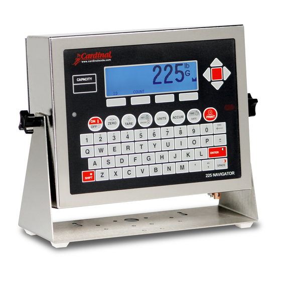
WEIGHT INDICATOR
Installation and Technical Manual
8200-M698-O1 Rev B
PO BOX 151 WEBB CITY, MO 64870
Printed in USA
11/14
PH (417) 673-4631 FAX (417) 673-5001
www.cardinalscale.com
Technical Support: Ph: 866-254-8261 techsupport@cardet.com
8200-M698-O1 Rev B 225 Installation and Technical
I
Advertisement
Table of Contents

Related Manuals for Cardinal 225


Summary of Contents for Cardinal 225
- Page 1 Installation and Technical Manual 8200-M698-O1 Rev B PO BOX 151 WEBB CITY, MO 64870 Printed in USA 11/14 PH (417) 673-4631 FAX (417) 673-5001 www.cardinalscale.com Technical Support: Ph: 866-254-8261 techsupport@cardet.com 8200-M698-O1 Rev B 225 Installation and Technical...
- Page 2 8200-M698-O1 Rev B 225 Installation and Technical...
- Page 3 Thank you for selecting and purchasing the Cardinal Model 225 Weight Indicator. The Model 225 indicator was built with quality and reliability at our factory in Webb City, Missouri and incorporates the latest in digital technology and innovative features for the weighing industry.
- Page 4 CAUTION: RISK OF EXPLOSION IF BATTERY IS REPLACED BY AN INCORRECT TYPE. DISPOSE OF USED BATTERIES ACCORDING TO THE INSTRUCTIONS. ATTENTION: RISQUE D'EXPLOSION SI LA BATTERIES EST REMPLACE'E PAR UN TYPE INCORRECT. REJETEZ LES BATTERIES UTILISE'ES SELON LES INSTRUCTIONS. 8200-M698-O1 Rev B 225 Installation and Technical...
-
Page 5: Table Of Contents
Main PCB Jumpers Page 30 RE-INSTALLING THE REAR PANEL Page 31 KEYPAD FUNCTIONS Page 32 Standard Function Keys Page 32 Alphanumeric Keys Page 35 Shift Key Combinations Page 36 Soft Keys Page 38 8200-M698-O1 Rev B 225 Installation and Technical... - Page 6 SETUP MENU #3 Page 86 ACCUMULATORS Page 86 BACK LIGHT Page 86 PASSWORD Page 87 2XX- (2XX OPTION CARD) Page 87 BADGE READER Page 88 KEY LOCKOUT Page 90 LOCAL REMOTE PORT Page 91 8200-M698-O1 Rev B 225 Installation and Technical...
- Page 7 ELECTRONIC TALLEY ROLL (ETR) FILE Page 133 SCALE ID Page 135 DELETING CUSTOM TICKETS Page 136 PRINT SETUP Page 137 LEAD AND WIRE SECURITY SEAL INSTALLATION Page 139 PART IDENTIFICATION Page 140 8200-M698-O1 Rev B 225 Installation and Technical...
-
Page 9: Specifications
Signal Input Range: 1.0 mV min. to 40 mV max. (with dead load boost) Scales 1 ea Standard, 3 ea with optional 225-DS Dual Scale Input Board Number of Load Cells: 14 each, 350-ohm load cells 1,500 feet maximum (requires the use of sense lines). Consult... -
Page 10: Features
Any application affected by vibration or movement on ® the scale platform can benefit using StableSENSE 8200-M698-O1 Rev B 225 Installation and Technical... -
Page 11: Precautions
ALWAYS store and transport electronic printed circuit cards and components in anti-static protective bags or packaging. 8200-M698-O1 Rev B 225 Installation and Technical... -
Page 12: Site Preparation
SITE PREPARATION REQUIREMENTS The Model 225 Weight Indicator is a precision weight-measuring instrument. As with any precision instrument, it requires an acceptable environment to operate at its peak performance and reliability. This section is provided to assist you in obtaining such an environment. -
Page 13: Electrical Power
SITE PREPARATION REQUIREMENTS, CONT. Electrical Power The 225 has been designed to operate from 100 to 240 VAC @ 0.4A Max. at 50/60 Hz. Note that a special order is not required for operation at 230/240 VAC. WARNING! To avoid electrical hazard and possible damage to the indicator, DO NOT, under any circumstance, cut, remove, alter, or in any way bypass the power cord grounding prong. -
Page 14: Rfi Immunity
RFI (Radio Frequency Interference) in a digital weight indicator is weight indication instability during a radio transmission. Cardinal digital weight indicators are designed with special grounding and RFI shielding to achieve a high degree of immunity to common RFI. To maximize the digital weight indicator’s immunity to radio transmissions, follow these guidelines: 1. -
Page 15: Installation
The Model 225 Indicator is housed in a Stainless Steel wall or desk-mount enclosure. The 225 gimbal may be mounted on a desk, table or other smooth, flat, horizontal surface or may be mounted on a wall. -
Page 16: Load Cell Connections
3. Referring to Figure No. 3, route the single cable from the load cell or load cell junction box through the nut and plastic insert and into the enclosure. Figure No. 3 8200-M698-O1 Rev B 225 Installation and Technical Figure No. 2... - Page 17 Insert the wire into the opening and remove the screwdriver, allowing the release bar to return to its original position, locking the wire in place. See Figure No. 5. Press Down Insert Wire Figure No. 5 8200-M698-O1 Rev B 225 Installation and Technical...
- Page 18 Wire 12. The shield wire is secured when tightening the gland connector nut. See Figure No. 7. Figure No. 7 13. Do not over-tighten the connector but make certain it is snug. 8200-M698-O1 Rev B 225 Installation and Technical...
-
Page 19: Load Cell Cable Connection Without Rfi Suppression
+SENS, -SENS terminals of the load cell trim board or the section seal trim board. For the indicator to use the sense wires, the +SENS jumper J7 and the -SENS jumper J9 must be open (see Figure No. 13). 8200-M698-O1 Rev B 225 Installation and Technical... -
Page 20: Serial I/O Cable Installation
INSTALLATION, CONT. Serial I/O Cable Installation The 225 may be connected to a printer to record weight and associated data or it may be connected to a remote display or even to a computer for transmission of weight data. The weight data may be transmitted on demand (pressing the PRINT key or on receipt of a command from the computer). -
Page 21: Serial Ports Specifications (Continuous Or On Demand Output)
3. SETUP MENU #2, SERIAL, PORT, SCALE=0, CONT=YES outputs continuous weight of the selected (active) scale out the designated port for multi-scale operation. * Mutually exclusive 8200-M698-O1 Rev B 225 Installation and Technical... - Page 22 NOTE: The serial port used for the PRINT key is selected in the PRINT TABS menu, PORT= 0 (COM0) PORT= 1 (COM1) PORT= 2 (COM2) PORT= 3 (COM3/USB) NOTE: Multi-scale printing prints the selected (active) scale out the selected port. 8200-M698-O1 Rev B 225 Installation and Technical...
-
Page 23: Usb Interface And Usb Cable Installation
INSTALLATION, CONT. USB Interface The 225 indicator USB Interface is a standard full speed (12Mbps) USB 2.0 device port. It can be connected to a USB 2.0 host, with the Cardinal Scale 8200-B163-0A USB CABLE or a industry standard USB 2.0 cable, to be used as the COM3 serial I/O port set to 8 bit data, 1 stop bit, no parity, 9600 to 115.2k baud. - Page 24 3. Slip the cable through the hole in the rear panel and into the enclosure. 4. Plug the USB cable into the USB-B connector P6. See Figure No. 15 for the location of P6. 8200-M698-O1 Rev B 225 Installation and Technical...
-
Page 25: I/O Ports Interconnections
Interconnect Wiring for COM0/COM1 20mA Current Loop Operation Peripheral Device has PASSIVE END of Current Loop. SERIAL I/O TxD1 (COM0/COM1) TxD0-RS232 Rx RETURN TxD1-SRC TxD1-20mA + Rx ACTIVE TxD1-20mA – Peripheral Device RxD1-RS232 TxD1-RS232 Internal Circuitry RxD0-RS232 TxD0-20mA Active 8200-M698-O1 Rev B 225 Installation and Technical... - Page 26 Peripheral Device has PASSIVE END of Current Loop. SERIAL I/O TxD2 (COM2/COM3) TxD2-SRC Rx RETURN TxD2-20mA + Rx ACTIVE TxD2-20mA – RxD2-SRC Tx RETURN RxD2-20mA + Tx ACTIVE Internal RxD2-20mA – Circuitry RxD2-RS232 TxD2-RS232 Peripheral Device GND2 RxD3-RS232 TxD3-RS232 8200-M698-O1 Rev B 225 Installation and Technical...
-
Page 27: Optically Isolated Remote Inputs
Remember that the input must be connected to GND to initiate the function. AC Input Relay Board(s) The AC Input Relay Board(s) are mounted in an external junction box for use with the 225 Indicator. The RB4-ACIN (115 VAC) or RB4-ACINV (230 VAC) contain one board and supports 4 inputs (jumper selectable). - Page 28 Figure No. 5 Relay Box Assembly RB4-ACIN or RB8-ACIN Relay Box Assembly RB4-ACINV or RB8-ACINV NOTE: AC INPUT RELAYS ARE VOLTAGE DEPENDENT. A DIFFERENT RELAY IS REQUIRED FOR 115 VAC AND 230 VAC! 8200-M698-O1 Rev B 225 Installation and Technical...
-
Page 29: Preset Weight Comparator/Checkweigher Logic Level Output
INSTALLATION, CONT. Preset Weight Comparator/Checkweigher Logic Level Output If you so choose, you may use the logic level outputs from your Model 225 indicator’s preset weight comparators or checkweigher to control peripheral devices used to manage the flow of material or signal when the weight is within preset limits. Note that these outputs are at logic level and cannot drive external devices directly, with the exception of the Cardinal 2XX-OU CHECK WEIGHER LIGHT BAR. - Page 30 INSTALLATION, CONT. AC Output Relay Board(s), Cont. 225 Indicator – P18 Figure No. 10 Relay Box Assembly RB4-ACOUT or RB8-ACOUT 8200-M698-O1 Rev B 225 Installation and Technical...
- Page 31 INSTALLATION, CONT. AC Output Relay Board(s), Cont. 225 Indicator – P19 Figure No. 11 Relay Box Assembly RB4-ACOUT or RB8-ACOUT 8200-M698-O1 Rev B 225 Installation and Technical...
-
Page 32: Dc Output Relay Board(S)
INSTALLATION, CONT. DC Output Relay Board(s) The DC Output Relay Boards are mounted in an external junction box for use with the 225 Indicator and can be purchased from Cardinal. The RB4-DCOUT contains one board and supports four outputs (jumper selectable). The RB8-DCOUT contains two boards and supports eight outputs. - Page 33 INSTALLATION, CONT. DC Output Relay Board(s), Cont. DC DC 225 Indicator – P19 3 to 60 VDC 3A max. Figure No. 12 Relay Box Assembly RB4-DCOUT or RB8-DCOUT 8200-M698-O1 Rev B 225 Installation and Technical...
- Page 34 INSTALLATION, CONT. DC Output Relay Board(s), Cont. DC DC 225 Indicator – P18 3 to 60 VDC 3A max. Figure No. 13 Relay Box Assembly RB4-DCOUT or RB8-DCOUT 8200-M698-O1 Rev B 225 Installation and Technical...
-
Page 35: Rb4C Relay J-Box
Relay Control Source Type Jumpers, J1, J2, J3, and J4 (see Figure No. 14), one for each relay. Figure No. 14 (Relay Control Source Type Jumpers) RB4C Control Circuit Wiring Example 8200-M698-O1 Rev B 225 Installation and Technical... -
Page 36: Main Pc Board I/O Functions Table
The relay box cable wire numbers correspond to the indicator main PC board remote input (P17) and output (P19 and P18) terminal connection pins. CABLE WIRE RELAY NUMBER CABLE WIRE RELAY NUMBER NUMBER (Set Proper Jumpers) NUMBER (Set Proper Jumpers) +SRC (For AC Input Relays) 8200-M698-O1 Rev B 225 Installation and Technical... -
Page 37: Main Pcb
This board contains static sensitive components. Improper handling can result in damage to or destruction of the components or board. Such actual and/or consequential damage IS NOT covered under warranty. Figure No. 15 8200-M698-O1 Rev B 225 Installation and Technical... -
Page 38: Main Pcb Jumpers
J8 (REMOTE IN) – REMOTE IN SRC (SOURCE) When installed, this jumper allows the 225 indicator to supply (source) 5 VDC to a remote input circuit. Connecting P17 pins 1 through 9 to P17 pin 10 (GND) through a switch will cause the selected action. -
Page 39: Re-Installing The Rear Panel
MAIN PC BOARD, CONT. P8 (CAL) – CALIBRATION INHIBIT JUMPER When installed, this jumper inhibits (prevents) calibration of the 225 indicator. When removed, CAL will be shown on the display (to indicate calibration is allowed) and calibration of the 225 indicator can be performed. -
Page 40: Keypad Functions
KEYPAD FUNCTIONS The Model 225 indicator has 8 standard function keys, a full “QWERTY” alpha-numeric keypad, 4 soft (programmable) keys and 4 navigation keys with an interactive ENTER key. The keypad is used to enter commands and data into the indicator. This section describes each key along with its normal function. - Page 41 OPERATION sections of this manual for more information. TIME/DATE KEY This key is used to program the time, date and consecutive number. Refer to the TIME, DATE AND CONSECUTIVE NUMBER section of this manual more information. 8200-M698-O1 Rev B 225 Installation and Technical...
- Page 42 PRINT keys in combination (refer to the Shift Key section for details). NOTE: When the PRINT key is pressed the indicator looks for the selected format. If no VISUALIZER ticket is found it reverts to the print tab settings. 8200-M698-O1 Rev B 225 Installation and Technical...
-
Page 43: Alphanumeric Keys
This key is used to enter a blank space during alphanumeric data input for Calibration and Setup as well as during normal operations. When combined with the SHIFT key, it is used to decrease the display contrast. 8200-M698-O1 Rev B 225 Installation and Technical... -
Page 44: Shift Key Combinations
Shift Key Combinations SHIFT, ESC, ACCUM KEY The 225 will retain and display on command the maximum weight value measured since the indicator has begun operation or since the maximum value was last cleared. The maximum value is displayed by pressing the SHIFT key, the ESC key and then the ACCUM key when the display is showing the FUNCTION= prompt. - Page 45 SHIFT AND TARE KEY This combination is used during normal operations to display the current Tare weight. The tare weight will be displayed for 3 seconds and then the 225 will return to normal operations. SHIFT, UNITS KEY This combination will enter the Test mode. Refer to the TEST MODE AND ERASING MEMORY section of this manual for more information.
-
Page 46: Soft Keys
Refer to the PRESET WEIGHT COMPARATORS OPERATION section of this manual for more information. COUNT KEY This key is used by the Counting feature. Refer to the Operation, COUNTING FEATURE OPERATION section of this manual for more information. 8200-M698-O1 Rev B 225 Installation and Technical... -
Page 47: Annunciators
This annunciator is turned on to show that the displayed weight is the Net weight (Gross weight less Tare weight). This annunciator is turned on to indicate that the displayed weight is the tare weight. 8200-M698-O1 Rev B 225 Installation and Technical... - Page 48 This annunciator is turned on to indicate that the displayed weight is kilograms, for example, t (TONNES “METRIC TONS”) This annunciator is turned on to show that the displayed weight measurement is metric tons, for example, 8200-M698-O1 Rev B 225 Installation and Technical...
-
Page 49: Time, Date And Consecutive Number
12. If the consecutive number displayed is correct, press the ENTER key to return to normal operations. 13. Otherwise, using the numeric keys, enter the new consecutive number (6 digits max.) and then press the ENTER key to return to normal operations. 8200-M698-O1 Rev B 225 Installation and Technical... -
Page 50: Display Contrast Adjustment
ENTER key to return to normal operations. DISPLAY CONTRAST ADJUSTMENT The Model 225 indicator uses a combination of the SHIFT, ENTER and SPACE keys to adjust the contrast of the LCD display. To Increase the LCD Contrast 1. -
Page 51: Calibration And Setup
CALIBRATION AND SETUP Security Seals A Category 1 Audit Trial is provided on the Model 225 with two event counters that increment when a change is made to features that are required by NTEP or OIML to be sealed. One counter is designated for calibration parameters and one is designated for configuration changes as required in NCWM Publication 14, 2007. - Page 52 CALIBRATION AND SETUP, CONT. Your 225 indicator has been thoroughly tested and calibrated before being shipped to you. If you received the indicator attached to a scale, calibration is not necessary. If the indicator is being connected to a scale for the first time or recalibration is necessary for other reasons, proceed as indicated.
-
Page 53: Enter Calibration And Setup
ETR able = YES PT printed with tare. Lamp test on power up. Lorry Weigher Operation (Any MODE OF OP but 1 or 6). NSC (Australia NSC Requirements) setup parameter selection allowed 8200-M698-O1 Rev B 225 Installation and Technical... - Page 54 CALIBRATION AND SETUP, CONT. 2. NSC=XXX (AUSTRALIA NSC REQUIREMENTS) NOTE: In countries requiring the 225 to meet Australia NSC requirements, the USA= parameter must be set for international use (USA=NO) to allow the 2. NSC=XXX setup parameter selection. With SETUP MENU #1 displayed the current setting for the NSC= parameter will be shown.
- Page 55 Otherwise, press the 7 key, the ENTER key, YES or NO (on the soft keys) and then the ENTER key to save the new setting and return to SETUP MENU #1. CLR ID=YES CLR ID= NO Automatically clears ID after print ID is not cleared after print 8200-M698-O1 Rev B 225 Installation and Technical...
- Page 56 9. TOTALIZE=XXX (SCALE TOTALIZER) With the 225-DS (Dual Scale) Card installed and the number of scales set for 2 or 3, the 225 can sum the weights of two or more scales and make the total available to be displayed.
- Page 57 2. Digital Fill Ctrl (Digital Fill Control = DFC) Press the 2 key and then the ENTER key to proceed to the Digital Fill Control Menu. Refer to the 225 Digital Fill Control manual. 3. Preset Weight Comp (Preset Weight Comp = PWC) Press the 3 key and then the ENTER key to proceed to the Preset Weight Comparator Menu.
-
Page 58: Setup Menu #2
COM0 SETUP MENU. COM0 SETUP MENU 1. BAUD=X XXXXXX 6. TYPE=X XXXXXXXXXX 2. PARITY=X XXXX 7. SCALE = 0 3. BITS=X 8. Gross Only = NO 4. STOPS=X 5. CONT=XXX Enter Selection: 0 EXIT 8200-M698-O1 Rev B 225 Installation and Technical... - Page 59 Otherwise, press the 4 key, the ENTER key and then using the numeric keys, enter the value for the COM0 stop bits and then press the ENTER key to save the new setting and return to the COM0 SETUP MENU. Allowable values are 1 or 2. 8200-M698-O1 Rev B 225 Installation and Technical...
- Page 60 ENTER key: PRINTR CONTINUOUS OUTPUT SELECTION TOLEDO FORMAT SELECTION MENU 0. 8530 no CKSUM 1. SHORT no CKSUM 2. 8530 with CKSUM 3. SHORT with CKSUM TOLEDO Format=X 8200-M698-O1 Rev B 225 Installation and Technical...
- Page 61 COM ports. NOTE: If you selected 5. SB500 or 6. SB250/500M for the TYPE= parameter, the following setup parameters Manual Mode= and Thres Wt= will be shown on the COM0 SETUP MENU. 8200-M698-O1 Rev B 225 Installation and Technical...
- Page 62 (turned off). COM0 Setup Completed The COM0 setup has been completed, press EXIT (Navigation Keys UP Arrow) to return to the Serial Menu and proceed to the COM port (serial port) setup. 8200-M698-O1 Rev B 225 Installation and Technical...
- Page 63 CALIBRATION AND SETUP, CONT. The following describes the setup for the 225 COM ports (Serial Ports). Although the three (3) COM ports can be configured differently, they have the same setup parameters. In the setup menus shown and parameters described, COM1 (Serial Port 1) is referenced.
- Page 64 Otherwise, press the 5 key, the ENTER key, YES or NO (on the soft keys) and then the ENTER key to save the new setting and return to the COM1 SETUP MENU. CONT=YES CONT=NO Continuous Output Enabled Continuous Output Disabled 8200-M698-O1 Rev B 225 Installation and Technical...
- Page 65 Allowable values are 0, 1, 2, or 3. NOTE 2! 9=TALLEY is displayed only if USA=NO and MODE OF OP=0, 2, 3, 4 or 5. Refer to the ELECTRONIC TALLEY ROLL section of this manual. 8200-M698-O1 Rev B 225 Installation and Technical...
- Page 66 Manual Mode=NO Manual Mode is Enabled. Pressing Manual Mode is Disabled. START/STOP key will toggle traffic Threshold weight is used to toggle light between Green and Red. light between Green and Red. 8200-M698-O1 Rev B 225 Installation and Technical...
- Page 67 Proceed to the next setup parameter. Press PREV (Navigation Keys UP Arrow) to return to SETUP MENU #1. Press NEXT (Navigation Keys Down Arrow) to proceed to the SETUP MENU #3. 8200-M698-O1 Rev B 225 Installation and Technical...
-
Page 68: Dio Setup (Pwc Status)
Otherwise, press the PWC number, 17 or 18 to toggle the status (turn ON, relay closed or OFF, relay open) and then press the ENTER key to save the new setting. IMPORTANT! When power to the indicator is lost, the output goes to the OFF state. 8200-M698-O1 Rev B 225 Installation and Technical... - Page 69 Proceed to the next setup parameter. Press PREV (Navigation Keys UP Arrow) to return to SETUP MENU #1. Press NEXT (Navigation Keys Down Arrow) to proceed to the SETUP MENU #3. 8200-M698-O1 Rev B 225 Installation and Technical...
-
Page 70: Print Tabs Setup
ENTER key to save the new setting and return to PRINT TABBING MENU #1. Allowable values are 0 through 3. 0 = COM0 1 = COM1 2 = COM2 3 = COM3 8200-M698-O1 Rev B 225 Installation and Technical... - Page 71 HEX numbers are always 2 digits. For example, 7 is entered as 07. The maximum entry is 6 numbers (12 characters). Valid entries are 01 through FF. Note that 00 is not valid. 8200-M698-O1 Rev B 225 Installation and Technical...
- Page 72 Otherwise, press the 8 key, the ENTER key and then using the numeric keys, enter the new print position and then press the ENTER key to save the new setting and return to PRINT TABBING MENU #1. 8200-M698-O1 Rev B 225 Installation and Technical...
- Page 73 Otherwise, press the 1 key twice, the ENTER key and then using the numeric keys, enter the new print position and then press the ENTER key to save the new setting and return to PRINT TABBING MENU #2. 8200-M698-O1 Rev B 225 Installation and Technical...
- Page 74 Otherwise, press the 1 and 5 keys, the ENTER key and then using the numeric keys, enter the new print position and then press the ENTER key to save the new setting and return to PRINT TABBING MENU #2. 8200-M698-O1 Rev B 225 Installation and Technical...
- Page 75 Units Net Weight print feature. NOTE: The CNV NET= weight will only print if the converted weight is greater than zero and the 225 in is the Net mode. With PRINT TABBING MENU #2 displayed the current setting for the CNV NET= parameter will be shown.
-
Page 76: Setup Scale
The following describes the Scale Setup for the 225. The standard 225 supports one (1) scale. With the optional 225-DS Dual Scale card installed, it can support up to three (3) scales. In the setup menus shown and parameters described, Scale 1 is referenced. - Page 77 Otherwise, press the 4 key, the ENTER key, YES or NO (on the soft keys) and then the ENTER key to save the new setting and return to the PUO = YES PUO = NO Automatic Re-Zero on Power-Up No Re-Zero on Power-Up 8200-M698-O1 Rev B 225 Installation and Technical...
- Page 78 ENTER key to save the new setting and return to SCALE 1 SETUP MENU #1. Allowable values are 1 or 2. WT INTERVAL=1 WT INTERVAL=2 Single Interval (One weight range) Dual Interval (Two weight ranges) 8200-M698-O1 Rev B 225 Installation and Technical...
- Page 79 CALIBRATION AND SETUP, CONT. 9. WT INTERVAL=X (WEIGHT INTERVAL “SINGLE OR DUAL”), CONT. CAUTION! When using the dual interval feature of the 225, do not attempt to use a division value in the low range that is too small to provide adequate signal strength for stable operation of the indicator.
- Page 80 ENTER key to save the new setting and return to SCALE 1 SETUP MENU #2. Allowable values are 1 through 255. 8200-M698-O1 Rev B 225 Installation and Technical...
-
Page 81: Filter Setting Recommendations
3. FMAX= MAXIMUM FILTER LEVEL (0 to 255) determination: Set to desired results. 4. If stability is unacceptable with any setting of FMAX=, reduce the sample rate and/or increase the break range, FBRK= setting for increased filtering. 8200-M698-O1 Rev B 225 Installation and Technical... - Page 82 ENTER key to save the new setting and return to SCALE 1 SETUP MENU #2. If the 225 is used in a Legal For Trade application (LFT=YES), allowable values are 1, 2, 5, 10, 20 or 50.
- Page 83 Proceed to the next setup parameter. Press PREV (Navigation Keys UP Arrow) to return to SETUP MENU #1. Press NEXT (Navigation Keys Down Arrow) to proceed to the SETUP MENU #3. 8200-M698-O1 Rev B 225 Installation and Technical...
-
Page 84: Calibrate
Each number may be up to three digits in length. The “C” numbers are established when the scale is calibrated. By recording these numbers, the indicator can be returned to its present calibration settings without using test weights simply by entering the “C” numbers. 8200-M698-O1 Rev B 225 Installation and Technical... -
Page 85: Calibration Methods
CALIBRATION AND SETUP, CONT. CALIBRATION METHODS The 225 has two methods to enter the calibration procedure. One method is selected from the SETUP/REVIEW MENU and the other method selected from SETUP MENU #2. From SETUP/REVIEW MENU: With the SETUP/REVIEW MENU displayed, press the 3 key and then the ENTER key. This method proceeds directly to a display showing the settings for the capacity, interval, decimal point position and the first calibration parameter, CAL 1=0.0. - Page 86 (or if the need arises to recalibrate the scale) and test load (weights) are not available. By entering the previously recorded numbers, the indicator can be returned to its present calibration settings without using test load (weights). 8200-M698-O1 Rev B 225 Installation and Technical...
-
Page 87: Multi-Point Calibration
4. The display will flash CALIBRATING... for a few seconds and then change to show the SCALE 1 CALIBRATION MENU. NOTE: If Span Adjustment is required, proceed to the FINE SPAN ADJUSTMENT on page 70. 8200-M698-O1 Rev B 225 Installation and Technical... -
Page 88: Dual-Point With Zero (First Zero) Calibration
The display will show CAL 3=. This weight is not used. Press the ENTER key to skip CAL 3=. The display will change to show the SCALE 1 CALIBRATION MENU. NOTE: If Span Adjustment is required, proceed to the FINE SPAN ADJUSTMENT on page 70. 8200-M698-O1 Rev B 225 Installation and Technical... -
Page 89: Dual-Point Without Zero (False Zero) Calibration
1. Remove the weights on the scale, and then press the NET/GROSS key. 2. The display will change to show the SCALE 1 CALIBRATION MENU. NOTE: If Span Adjustment is required, proceed to the FINE SPAN ADJUSTMENT on page 70. 8200-M698-O1 Rev B 225 Installation and Technical... -
Page 90: Single-Point For Zero Only (Only Zero) Calibration
1. Press the ZERO key. 2. The display will change to show the SCALE 1 CALIBRATION MENU. NOTE: If Span Adjustment is required, proceed to the FINE SPAN ADJUSTMENT on page 70. 8200-M698-O1 Rev B 225 Installation and Technical... -
Page 91: Fine Span Adjustment (During Calibration)
Press EXIT (Navigation Keys Left Arrow) to save the new setting and return to the SCALE 1 CALIBRATION MENU. Press the ZERO key to zero the scale. Press the PRINT key to print the weight (followed by the text TEST). 8200-M698-O1 Rev B 225 Installation and Technical... -
Page 92: Calibration Parameters
Zero count and then press the ENTER key to save the new setting and return to the SCALE 1 CALIBRATION MENU. Allowable values are 1 through 9,999,999. Note that the capacity cannot exceed 7 digits or 9,999,999. 8200-M698-O1 Rev B 225 Installation and Technical... -
Page 93: Calibration "C" Numbers
With the SETUP MENU #2 displayed, Press PREV (Navigation Keys UP Arrow) to return to SETUP MENU #1. Press NEXT (Navigation Keys Down Arrow) to proceed to the SETUP MENU #3. 8200-M698-O1 Rev B 225 Installation and Technical... -
Page 94: Setup Menu #3
Otherwise, press the 2 key and then the ENTER key. The display will change to show the current light level (Lights= XX). SETUP MENU #3 Lights= XX BACK LITE = XX 8200-M698-O1 Rev B 225 Installation and Technical... -
Page 95: Password
4. 2XX- (2XX OPTION CARD) This prompt will ONLY be displayed when a 2XX Option Card is installed in the indicator. Refer to the manual for the 2XX option card installed for setup instructions. 8200-M698-O1 Rev B 225 Installation and Technical... -
Page 96: Badge Reader
3 = HID 5 = FLEXPASS NOTE: If you selected 1 = AWID for the TYPE= parameter, the setup parameter 4. SITE ID= will be shown on the BADGE READER SETUP Menu. 8200-M698-O1 Rev B 225 Installation and Technical... - Page 97 ENTER key to save the new setting and return to the BADGE READER SETUP Menu. SITE ID=YES SITE ID=NO Badges must have 3-digit Site ID to Badge Reader will work without be valid Site ID on badges 8200-M698-O1 Rev B 225 Installation and Technical...
-
Page 98: Key Lockout
6. Continue with this procedure until the status of each key has been entered. 7. After the last key lockout status has been entered, press the ENTER key to exit and return to SETUP MENU #3. 8200-M698-O1 Rev B 225 Installation and Technical... -
Page 99: Local Remote Port
With the SETUP MENU #3 displayed, Press PREV (Navigation Keys UP Arrow) to return to SETUP MENU #2. Press EXIT (Navigation Keys Down Arrow) to return to the SETUP/REVIEW MENU. 8200-M698-O1 Rev B 225 Installation and Technical... -
Page 100: Id Storage Setup (Mode Of Operation = 1)
ID COUNT=2 ID COUNT=3 One Prompt Two Prompts Three Prompts The value selected for ID COUNT will determine the number of additional prompts (PROMPT X=) displayed on the ID Storage Menu. 8200-M698-O1 Rev B 225 Installation and Technical... - Page 101 3. Press NEXT (Navigation Keys Down Arrow) to proceed to the SETUP MENU #2. 4. Press EXIT (Navigation Keys UP Arrow) to return to the SETUP/REVIEW MENU. 5. Press EXIT (Navigation Keys UP Arrow) to reset the indicator and return to normal operations. 8200-M698-O1 Rev B 225 Installation and Technical...
-
Page 102: Preset Weight Comparators Setup (Mode Of Operation = 3)
The relay state is based on using Cardinal Scale relays (p/n 6850-1013). If using relays other than those supplied by Cardinal Scale, refer to the relay manufacturers specifications. NOTE: When power to the 225 is lost, the output returns to a Low State condition. 8200-M698-O1 Rev B 225 Installation and Technical... - Page 103 3. Press NEXT (Navigation Keys Down Arrow) to proceed to the SETUP MENU #2. 4. Press EXIT (Navigation Keys UP Arrow) to return to the SETUP/REVIEW MENU. 5. Press EXIT (Navigation Keys UP Arrow) to reset the indicator and return to normal operations. 8200-M698-O1 Rev B 225 Installation and Technical...
-
Page 104: Count Operation
Because of variation of individual container weights, be certain to "tare off" each container by placing the empty container on the scale and pressing the ZERO key before proceeding with the count operation. 8200-M698-O1 Rev B 225 Installation and Technical... -
Page 105: Id Storage Operation
ID string is entered and the stored weight is recalled for printing the complete ticket. After the ticket has printed, the ID number and the stored weight will be removed from memory. 8200-M698-O1 Rev B 225 Installation and Technical... - Page 106 Using the numeric keys, enter the desired alarm TIME ON=X value (1-99 seconds) and press the ENTER key. The on time will be stored and the display will return to normal mode. Note that setting TIME ON=0 disables the alarm. 8200-M698-O1 Rev B 225 Installation and Technical...
- Page 107 ID STORAGE OPERATION, CONT. The following describes the ID Storage operation for the 225 with the ID Count set for one prompt. Therefore, only one prompt name is referenced. Substitute the prompt name entered during ID Storage Setup for the prompt name shown. Note that with the ID Count set for more than one prompt, additional steps will be displayed.
- Page 108 1. With the indicator in normal operations mode, press the MEM key. The display will change to show Id=. 2. Press the PRINT key. The display will show Printing while all currently stored ID strings are printed. 3. The indicator will return to normal operation. 8200-M698-O1 Rev B 225 Installation and Technical...
- Page 109 8. The Net weight will be added to the accumulator of the entered ID string and the ticket printed will show the TIME, DATE, ID, TIME/DATE of Stored Tare weight, the Gross, Tare, and Net weights. 8200-M698-O1 Rev B 225 Installation and Technical...
- Page 110 10. The Net weight will be added to the accumulator of the entered ID string and the ticket printed will show the TIME, DATE, ID, TIME/DATE of Stored Tare weight, the Gross, Tare, and Net weights. 8200-M698-O1 Rev B 225 Installation and Technical...
- Page 111 5. The Net weight will be added to the accumulator of the entered ID string and the ticket printed will show the TIME, DATE, ID, TIME/DATE of Stored Tare weight, the Gross, Tare, and Net weights. 8200-M698-O1 Rev B 225 Installation and Technical...
- Page 112 5. The Net weight will be added to the accumulator of the entered ID string and the ticket printed will show the TIME, DATE, ID, TIME/DATE of Stored Tare weight, the Gross, Tare, and Net weights. 8200-M698-O1 Rev B 225 Installation and Technical...
- Page 113 5. The Net weight will be added to the accumulator of the entered ID string and the ticket printed will show the TIME, DATE, ID, TIME/DATE of Stored Tare weight, the Gross, Tare, and Net weights. 8200-M698-O1 Rev B 225 Installation and Technical...
- Page 114 2. The display will change to show ID1=. 3. Enter up to a 12-digit alphanumeric ID string and press the PRINT key. 4. The indicator will print a ticket, display Print Pass 2, and delete the ID string. 8200-M698-O1 Rev B 225 Installation and Technical...
- Page 115 2. The display will change to show ID1=. 3. Enter up to a 12-digit alphanumeric ID string and press the PRINT key. 4. The indicator will print a ticket, display Print Pass 2, and delete the ID string. 8200-M698-O1 Rev B 225 Installation and Technical...
- Page 116 2. The display will change to show ID1=. 3. Enter the ID string printed on the ticket and then press the PRINT key. 4. The indicator will print a ticket, display Print Pass 2, and delete the ID string. 8200-M698-O1 Rev B 225 Installation and Technical...
- Page 117 2. The display will change to show ID1=. 3. Enter the ID string printed on the ticket and then press the PRINT key. 4. The indicator will print a ticket, display Print Pass 2, and delete the ID string. 8200-M698-O1 Rev B 225 Installation and Technical...
-
Page 118: Preset Weight Comparators Operation
PRESET WEIGHT COMPARATORS OPERATION The Model 225 indicator has sixteen (16) outputs, which can be configured during the setup of the weight indicator to perform as Preset Weight Comparators “PWC”. If the PWC feature was selected during setup, the indicator will compare each enabled preset weight value with the displayed weight and then output a signal for each preset based on the comparison results. - Page 119 Preset weight value LESS its associated Trim weight value. Also, remember that the preset is based on the displayed weight, which can be either gross or net weight. 8200-M698-O1 Rev B 225 Installation and Technical...
- Page 120 Weight Comparators are always active unless a zero preset value was entered for the preset. IMPORTANT! Remember that the preset weight comparators function operates on the absolute value of the weight ignoring the polarity. 8200-M698-O1 Rev B 225 Installation and Technical...
-
Page 121: Accumulators
4. The Gross Weight accumulator will be reset to zero. 5. Press the NET/GROSS key, ENTER key or ESC (press SHIFT and then ) key to exit and return to normal operation. 8200-M698-O1 Rev B 225 Installation and Technical... - Page 122 3. The display will change to show the Piece Count Accumulator value. 4. Press the ZERO key. 5. The value for the Piece Weight accumulator will be reset to zero. 5. Press the ENTER key to return to normal operation. 8200-M698-O1 Rev B 225 Installation and Technical...
- Page 123 3. Press the PRINT key. 4. The display will show Printing. 5. The accumulator values for ALL active IDs will be printed. 6. The indicator will return to normal operation when printing has been completed. 8200-M698-O1 Rev B 225 Installation and Technical...
- Page 124 7. Press the ENTER key. 8. The accumulator values for ALL active IDs will be reset to zero. 9. The indicator will return to normal operation when all active IDs have been zeroed. 8200-M698-O1 Rev B 225 Installation and Technical...
-
Page 125: Continuous Output Formats
G = Gross, N = Net cc = Weight Status OC = over capacity CZ = center of zero MO = motion ee = weight not currently being displayed cr = Carriage Return (hex 0D) 8200-M698-O1 Rev B 225 Installation and Technical... - Page 126 Where: stx = Start of TeXt (hex 02) swa =, swb=, swc= Status Bytes xxxxxx= Displayed Weight, Gross or Net Weight (Six Digits) cr = Carriage Return (hex 0D) sum= Checksum Character 8200-M698-O1 Rev B 225 Installation and Technical...
- Page 127 SB250/500M – (Type= 6) %NDDDDDDDDD<CR> Where: N = Panel number for a daisy chain configuration D = Byte of data to display at respective location on the scoreboard <CR> = Carriage Return 8200-M698-O1 Rev B 225 Installation and Technical...
- Page 128 O = over capacity M = motion e = weight not currently being displayed uu = Units tn, lb, oz, t, kg, g Mode G = Gross, N = Net etx= End Text (hex 03) 8200-M698-O1 Rev B 225 Installation and Technical...
- Page 129 CONTINUOUS OUTPUT FORMATS, CONT. Weight on Demand Format If continuous output has not been selected for the COM Ports (CONT=NO), the 225 indicator will respond to a weight request (ENQ) as follows. The host device (computer) sends: ENQ - (hex 05) The 225 will respond: <s><xxxxxx><d><uu><m><cc><cr>...
- Page 130 CONTINUOUS OUTPUT FORMATS, CONT. SMA Weight on Demand Format If continuous output has not been selected for the COM Ports (CONT=NO), the 225 indicator will respond to a SMA weight request as follows. The host device (computer) sends: <lf> W <cr>...
-
Page 131: Ascii Commands
ASCII COMMANDS The Model 225 indicator will respond to ASCII coded serial data, in the format below, when input to the RXD serial input. The commands are ASCII strings, without spaces, followed by a carriage return <cr> and can be upper or lower case, or any combination. - Page 132 Gross and Net weight modes. (See Net, above). Error Responses Response Description Did not understand the command. MODE This command not supported by the mode of operation. For example: no Ing() if not batcher. 8200-M698-O1 Rev B 225 Installation and Technical...
-
Page 133: Troubleshooting
The Model 225 indicator is equipped with software that indicates when an error in the operation takes place. The following lists the error codes displayed by the 225 along with their meaning. Should you encounter an error code, please refer to this list for the cause. - Page 134 CORRECTIVE ACTION: Consult your scale service provider. FILE FULL The operator is attempting to add an ID when the ID file is full. CORRECTIVE ACTION: Determine the reason for the error display and take the appropriate corrective action. 8200-M698-O1 Rev B 225 Installation and Technical...
- Page 135 UNITS key pressed in an attempt to perform a “unit” conversion where the interval would have been less than .0001. CORRECTIVE ACTION: Determine the reason for the error display and take the appropriate corrective action. 8200-M698-O1 Rev B 225 Installation and Technical...
-
Page 136: Before You Call Service
CORRECTIVE ACTION: Consult your scale service provider. Before You Call Service The Model 225 indicator has been designed to provide you with years of trouble-free operation. In spite of this, troubles sometimes happen. Before calling for service assistance, you should make some initial checks to verify that a problem does exist. The following describes several types of symptoms along with suggested remedies. -
Page 137: Test Mode And Diagnostic Display
4. The display will show the model number and the software revision. 5. Next, a graphics display test will be performed. 6. After the display test, the 225 will display the calibration “C” numbers (C1 to C4) for approximately 5 seconds. -
Page 138: Erasing Memory
This includes the ID file, batcher info, dealer string, mode of operation, visual tickets). If a 225 does not display properly after a program update or otherwise becomes corrupt, perform the following: 1. With the indicator in normal operations mode, press the SHIFT key and then the Navigation ENTER key (red square key). -
Page 139: Fine Span Adjustment
Press EXIT (Navigation Keys Left Arrow) to save the new setting and return to the SCALE 1 CALIBRATION MENU. Press the Navigation Keys UP Arrow four (4) times to reset the indicator and return to normal operations. 8200-M698-O1 Rev B 225 Installation and Technical... -
Page 140: View Audit Trail Counters
VIEW AUDIT TRAIL COUNTERS A Category 1 Audit Trial is provided on the Model 225 with two event counters that increment when a change is made to features that are required by NTEP or OIML to be sealed. One counter is designated for calibration parameters and one is designated for configuration changes as required in NCWM Publication 14, 2007. -
Page 141: Electronic Talley Roll (Etr) File
(that cannot be modified) will be stored in memory. The 225 has sufficient memory to create an ETR file that will store up to 7000 transactions. The ETR file is structured such that when its capacity is reached, the newest transaction will replace the oldest. - Page 142 SMA XT command (also called TALLEY ON STABLE) to the weight indicator. Electronic Talley Roll (ETR) Format The host device (computing peripheral) sends: <0Ah><XT><ODh> The 225 weight indicator will respond by transmitting the following to the host device: <s><xxxxxx><d><uu><m><cc>#nnnnnn<cr> Where: Sign "-"...
-
Page 143: Scale Id
Otherwise, use the numeric keys to enter the new Scale ID and then press the ENTER key to save the new setting. Allowable values are: 0 through 99. Press EXIT (Navigation Keys UP Arrow) to reset the indicator and return to normal operations. 8200-M698-O1 Rev B 225 Installation and Technical... -
Page 144: Deleting Custom Tickets
4. After the last custom ticket has been deleted, press the ENTER key to return to the SETUP/REVIEW MENU. Press EXIT (Navigation Keys UP Arrow) to reset the indicator and return to normal operations. 8200-M698-O1 Rev B 225 Installation and Technical... -
Page 145: Print Setup
With the SETUP/REVIEW MENU displayed, press the 1 and 0 keys and then the ENTER key to print a hard copy of the 225 SETUP PARAMETERS. NOTE: The hard copy will print using the PRINTER SERIAL port with the parameters selected during Calibration and Setup and return to the SETUP/REVIEW MENU. - Page 146 8200-M698-O1 Rev B 225 Installation and Technical...
-
Page 147: Lead And Wire Security Seal Installation
LEAD AND WIRE SECURITY SEAL INSTALLATION If your Model 225 indicator is used in a commercial application and your local metrology laws require the use of physical sealing, a lead and wire security seal can be installed to prevent the rear panel from being removed from the indicator to gain access to the calibration jumper (P8) thereby preventing unauthorized access to the calibration adjustments. -
Page 148: Part Identification
PCB ASS’Y 225-INTL-ICAN CONTROLLER 8200-D360-08 KEYPAD: 225 DWI 8200-D365-0A WELDMENT: ENCLOSURE, FRONT 8200-D379-08 KEYPAD: 225 AU 6021-0661 SCW PAN-HEAD..MACHINE-SCW 06-32X.250 8200-C384-0A PCB ASS’Y 225CANP CAN INTERFACE 8200-C384-1A PCB ASS’Y 225CANG CAN INTERFACE Not Shown 8200-M698-O1 Rev B 225 Installation and Technical... - Page 149 PART IDENTIFICATION (Front Assembly) 8200-M698-O1 Rev B 225 Installation and Technical...
- Page 150 CABLE: AC POWER W/FILTER 205/210 DWI 8200-B238-0A CABLE 210-FE POWER SUPPLY OUTPUT 8200-B392-0A CABLE: AC POWER W/FILTER 205/210 DWI 8200-C363-08 POWER SUPPLY COVER 8200-C366-0A WELDMENT: ENCLOSURE, REAR 8510-C346-0I LABEL CAUTION HIGH VOLTAGE 8200-M698-O1 Rev B 225 Installation and Technical...
- Page 151 PART IDENTIFICATION (Rear Assembly) 8200-M698-O1 Rev B 225 Installation and Technical...
- Page 152 SUB-ASSY: FRONT ENCLOSURE - 225-SNAP 8200-D373-3A SUB-ASS'Y: FRONT ENCLOSURE, 225EU 8200-D373-4A SUB-ASS'Y: FRONT ENCLOSURE, 225 ICANG 8200-D373-5A SUB-ASS'Y: FRONT ENCLOSURE, 225 ICANP 8200-D373-6A SUB-ASS'Y: FRONT ENCLOSURE, 225ICANGEU 8200-D373-7A SUB-ASSY: FRONT ENCLOSURE, 225ICANPEU Not Shown 8200-M698-O1 Rev B 225 Installation and Technical...
- Page 153 PART IDENTIFICATION (Final Assembly) 8200-M698-O1 Rev B 225 Installation and Technical...
- Page 154 STATEMENT OF LIMITED WARRANTY WARRANTY TERMS Cardinal Scale Manufacturing Company warrants the equipment we manufacture against defects in material and workmanship. The length and terms and conditions of these warranties vary with the type of product and are summarized below:...
- Page 155 This warranty sets forth the extent of our liability for breach of any warranty or deficiency in connection with the sale or use of our product. Cardinal will not be liable for consequential damages of any nature, including but not limited to loss of profit, delays or expenses, whether based on tort or contract.
- Page 156 8200-M698-O1 Rev B 225 Installation and Technical...
Need help?
Do you have a question about the 225 and is the answer not in the manual?
Questions and answers