Cardinal SMARTCELL 225D Installation And Technical Manual
Hide thumbs
Also See for SMARTCELL 225D:
- Installation and technical manual (42 pages) ,
- Instructions manual (18 pages)

Related Manuals for Cardinal SMARTCELL 225D


Summary of Contents for Cardinal SMARTCELL 225D
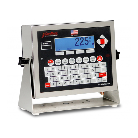
- Page 1 225D Weight Indicator Installation and Technical Manual 8200-0753-0M Rev D • 225D Weight Digital Indicator...
- Page 2 8200-0753-0M Rev D • 225D Weight Digital Indicator...
- Page 3 COPYRIGHT All rights reserved. Reproduction or use, without expressed written permission, of editorial or pictorial content, in any manner, is prohibited. No patent liability is assumed with respect to the use of the information contained herein. DISCLAIMER While every precaution has been taken in the preparation of this manual, the Seller assumes no responsibility for errors or omissions.
- Page 4 PROPER DISPOSAL When this device reaches the end of its useful life, it must be properly disposed of. It must not be disposed of as unsorted municipal waste. Within the European Union, this device should be returned to the distributor from where it was purchased for proper disposal. This is in accordance with EU Directive 2002/96/EC.
-
Page 5: Table Of Contents
TABLE OF CONTENTS INTRODUCTION ........... . Page 1 SPECIFICATIONS . -
Page 7: Introduction
The 225D consists of two main components: a 225 indicator with digital scale software, and a 225DLC controller (installed in the indicator option card slot). The scale must contain Cardinal Scale’s SCBD SmartCells or DC Digital Load Cells to communicate with the 225D. -
Page 8: Specifications
SPECIFICATIONS Power Requirements: 100 to 240V AC (50/60 Hz) at 0.4A Max. Enclosure Type: Stainless Steel wall or desk-mount Enclosure Size: 10 7/8"W x 8 3/16"H x 3 1/8"D (276mm W x 208mm H x 79mm D) Weight: 9.2lbs (4.2kg) Size and Weight DOES NOT include Gimbal Operating Environment: Temperature: 14 to 104 ºF (-10 to +40 ºC) Humidity: 90% non-condensing (maximum) -
Page 9: Homerun Cable Installation
HOMERUN CABLE INSTALLATION The Homerun Cable is installed between the 225D indicator and the first load cell in the loop (Start Node). Consult the chart below to determine the maximum Homerun Cable length. Note that the number of load cells in the scale determines the maximum length of the Homerun cable. - Page 10 Home Run Cable Connector Pack. Refer to the table below for cable and connector information. Cable and Connector Information ITEM and DESCRIPTION CARDINAL PART NO. HOMERUN CABLE, 5 CONDUCTORS, SHIELDED PVC 6980-1092 (CONTAINS 2 x 18AWG, 2 x 22AWG, AND 1 x 22AWG)
-
Page 11: Indicator Connection
Indicator Connection The homerun cable should be routed through the metallic gland connector installed in the 225D rear panel (lower right). Optional 2XX-USBA (Serial, Connectors Isolated Inputs or Outputs) AC Power 100-240 VAC (Serial, Isolated 0.4 Amp Max. Fiber Inputs or Optic Outputs) Cable... - Page 12 4. Route the homerun cable through the nut and plastic insert and into the enclosure. 5. With the homerun cable routed into the enclosure, remove approximately 2.0 inches (51 mm) of the cables’ outer jacket, exposing the internal wires. 6. Next, remove approximately 1/4 inch (6 mm) of insulation from each of the five wires. 7.
-
Page 13: Re-Installing The 225D Indicator Rear Panel
Re-Installing the 225D Indicator Rear Panel 1. After all terminations have been made, remove the excess cable from the indicator enclosure, and finger-tighten each of the cable gland connectors. 2. Ensure any unused gland connectors are plugged in and replace the rear panel. 3. - Page 14 LED 1-4 The LEDs are used for diagnostic purposes. For a complete explanation of their function, refer to the DIGITAL SCALE DIAGNOSTICS, Hardware Diagnostics section of this manual. Ethernet Port This port is used to connect the 225D to your network to send information to the cloud for iSite. Micro SD Card Slot The Micro SD card slot is not used at this time.
-
Page 15: Load Cell Connection
5-pin spring cage connector from the Homerun Cable Connector Pack. Refer to the table below for cable and connector information. Cable and Connector Information ITEM and DESCRIPTION CARDINAL PART NO. HOMERUN CABLE, 5 CONDUCTORS, SHIELDED PVC 6980-1092 (CONTAINS 2 x 18AWG, 2 x 22AWG, AND 1 x 22AWG) - Page 16 Refer to the Homerun Connector Wiring Color Code Table below when performing steps 4 through 7. Homerun Connector Wiring Color Code Table Connector Homerun Cable Wire Color if using a Signal Wire Color Load Cell Cable Pin Number Lever Color BROWN SHLD GRAY...
- Page 17 8. After all connections have been made, slide the black plastic and metal connector parts together, and then screw them together by hand-tightening. Slide both connector parts together and hand-tighten. 9. To complete the assembly, hold the black and metal parts of the connector housing, and then hand-tighten the cable clamp to the black plastic part of the connector housing.
-
Page 18: Setup And Configuration
SETUP AND CONFIGURATION All digital scales using Cardinal Scale’s SCBD SmartCell® or DC digital load cells are connected with a daisy-chained CAN (Controller Area Network) cable. The load cell connection loop can begin at any load cell and may continue clockwise as shown or counter-clockwise if preferred. -
Page 19: Addressing Cells
Addressing Cells Each cell has a serial number (S/N) marked on the cell. This is an eight-digit hexadecimal number. It is also known as the cell ID. Each cell ID must be matched with a cell address. In the tank/hopper example, the addresses would be 1-4. In the truck scale example, the addresses would be 1-8. -
Page 20: Calibration
Calibration If, after test loading the scale, it is determined that adjustments are required, follow the procedure below. Note that this section describes the procedure necessary to calibrate a Digital Truck Scale. 1. Before any adjustments are made, turn on the power to the 225D indicator. 2. -
Page 21: Smart Calibration
Center the weight over scale X and press ENTER to take a weight sample. Repeat steps 5, 6 for each cell in the order that the 225D prompts for. (This is the same order as other Cardinal scales e.g., 1, 3, 5, 7, 8, 6, 4, 2). ZERO CALIBRATION Zero Calibration does not affect the trimming of the cells or affect span. -
Page 22: Span Adjust
SPAN ADJUST Span adjust allows the user to tweak the span of the entire scale at once. Press 4 and ENTER. The 225D will display the current live scale weight “SCALE WT = XXXXX.X”. NOTE: High-resolution weight (interval/10) will be shown if the weight interval setting is less than 10. -
Page 23: Digital Scale Diagnostics
DIGITAL SCALE DIAGNOSTICS There are four main components to 225D Digital Scale Diagnostics: • On Screen Diagnostics – Critical errors that alert operator from the main screen of setup issues or hardware problems. • Diagnostic Menu – A set of diagnostic tools that give a technician more information about each load cell. - Page 24 COMMUNICATION ERROR BETWEEN LOAD CELLS X AND Y NO WEIGHT ------- COMMUNICATION ERROR BETWEEN LOAD CELLS 1 AND 3 COUNT Probable Cause Items to Check There is a loss of • Check that cable is connected correctly. communication between load •...
- Page 25 LOAD CELL X HAS BEEN REPLACED NO WEIGHT ------- LOAD CELL 2 HAS BEEN REPLACED. SCALE NOT LEGAL FOR TRADE UNTIL CALIBRATED. PRESS ENTER TO CONTINUE Probable Cause Items to Check A load cell has been replaced. Replaced load cells are automatically detected if only one load cell was replaced.
- Page 26 LOAD CELL ID 8F07E8F HAS NO ADDRESS NO WEIGHT ------- LOAD CELL ID 8F07E8F HAS NO ADDRESS COUNT Probable Cause Items to Check A load cell is responding, but Go to the addressing menu and assign the load cell ID to it is not addressed in the an address.
- Page 27 DIGITAL SCALE BOARD NOT DETECTED NO WEIGHT ------- DIGITAL SCALE CARD NOT DETECTED COUNT Probable Cause Items to Check The 225D cannot • Check that the card is seated properly and fastened communicate with the option correctly. card or the option card is not •...
-
Page 28: Diagnostic Menu
Diagnostic Menu To enter the diagnostic menu press SHIFT + CELL_DIAG soft key. All diagnostic information except software version updates once per second. LIVE LOAD CELL WEIGHTS (This can be zeroed as needed.) LOAD CELL WEIGHTS -106 -120 PREVIOUS NEXT EXIT MINIMUM AND MAXIMUM WEIGHTS (This can be zeroed as needed.) MAXIMUM / MINIMUM WEIGHTS... - Page 29 SOFTWARE VERSION OF CELL LOADCELL SOFTWARE VERSIONS 1. 1.0.14 6. 1.0.14 2. 1.0.14 7. 1.0.14 3. 1.0.14 8. 1.0.14 4. 1.0.14 5. 1.0.14 PREVIOUS NEXT EXIT NOTE: The controller’s version number, in contrast, is displayed upon startup of the 225D indicator.
- Page 30 WEIGHT ERROR COUNTS WEIGHT ERROR COUNTS 1. 0 6. 0 2. 0 7. 0 3. 0 8. 0 4. 0 5. 0 PREVIOUS NEXT EXIT CELL POWER SUPPLY VOLTAGES CELL POWER SUPPLY VOLTAGES *Approx. 14.355 14.191 13.950 14.530 14.334 14.260 14.211 14.267 * 0.184 Amps...
- Page 31 SNAP COMMUNICATIONS DIAGNOSTICS When the SNAP SmartMedia Box communications are enabled, an additional page of the Digital Scale Diagnostics is available. This will scan and list the IDs of any SmartMedia boxes that it finds on the same channel that the indicator is set to.
-
Page 32: Hardware Diagnostics
Hardware Diagnostics The 225DLC (Digital Load cell Controller) option card has four LEDs for diagnostic purposes. LED1 LED2 LED3 LED4 LED1 (RED) – MAIN BOARD TX/RX: Toggles each time the DLC controller and the 225D Mainboard exchange messages. LED2 (RED) – TX TO LOAD CELL: Toggles each time a message is sent from the DLC controller to the load cells. -
Page 33: Detecting Board Replacements
NEW card to the existing scale. OPTION CARD REPLACEMENT If an option card is replaced, the 225D will boot up to this screen: BY CARDINAL Revision 0.1.04 NEW CARD FOUND! WAS DIGITAL SCALE CARD REPLACED? NO The 225D will check whether the option card has been replaced, to reconfigure the new option card to the existing scale. -
Page 34: 225Dlc Card Replacement
225DLC CARD REPLACEMENT Remove this screw, washer, and the ground wire Remove the remaining three screws and lock washers Align pins on 225DLC card with holes in 8200-0753-0M Rev D • 225D Weight Digital Indicator... - Page 35 12. Re-insert the 225D power cord into the wall outlet. 13. Press the ON/OFF key on the 225D keypad to turn on the indicator. 14. The 225D will boot up to this screen: BY CARDINAL Revision 0.1.04 NEW CARD FOUND! WAS DIGITAL SCALE CARD REPLACED? NO 15.
-
Page 36: Isite Configuration
CONFIGURATION The 225D will periodically send indicator, scale, and cell data to the Cardinal iSite Webserver for diagnostic logging. This information will be used by the server to determine if there are problems with the scale(s) that need to be addressed. - Page 37 TO CHECK STATUS OF LAST ISITE CONNECTION, CONT. ISITE STATUS OF LAST CONNECTION IP = 10.1.3.109 ETHERNET DETECTED WAITING FOR SOCKET INIT HTTP RESP = 0 PREVIOUS NEXT EXIT The following information is available: A. IP address (if available). B. Ethernet cable state – “ETHERNET DETECTED” or “ETHERNET NOT DETECTED”...
- Page 38 FIRST PAGE OF WARRANTY 8200-0753-0M Rev D • 225D Weight Digital Indicator...
- Page 39 SECOND PAGE OF WARRANTY 8200-0753-0M Rev D • 225D Weight Digital Indicator...
- Page 40 Cardinal Scale Mfg. Co. 102 E. Daugherty, Webb City, MO 64870 USA Ph: 417-673-4631 or 1-800-641-2008 Fax: 417-673-2153 www.cardinalscale.com Technical Support: 1-866-254-8261 E-mail: tech@cardet.com Printed in USA 8200-0753-0M Rev D 11/19 8200-0753-0M Rev D • 225D Weight Digital Indicator...
Need help?
Do you have a question about the SMARTCELL 225D and is the answer not in the manual?
Questions and answers