Table of Contents
Advertisement
Advertisement
Table of Contents

Related Manuals for Cardinal 204


Summary of Contents for Cardinal 204
- Page 1 WEIGHT INDICATOR INSTALLATION and TECHNICAL MANUAL 8555-M313-01 Rev H 203 E. Daugherty, Webb City, MO 64870 USA Printed in USA Ph: 417-673-4631 Fax: 417-673-2153 01/14 www.cardinalscale.com Technical Support: Ph: 866-254-8261 • tech@cardet.com 8555-M313-O1 Rev H • 204 Installation & Technical...
- Page 2 8555-M313-O1 Rev H • 204 Installation & Technical...
- Page 3 Before You Call Service Page 21 204 Parts Identification Page 22...
-
Page 4: Fcc Compliance Statement
Seller is not able to guarantee the result of any procedure contained herein. Nor can they assume responsibility for any damage to property or injury to persons occasioned from the procedures. Persons engaging the procedures do so entirely at their own risk. 8555-M313-O1 Rev H • 204 Installation & Technical... -
Page 5: Specifications
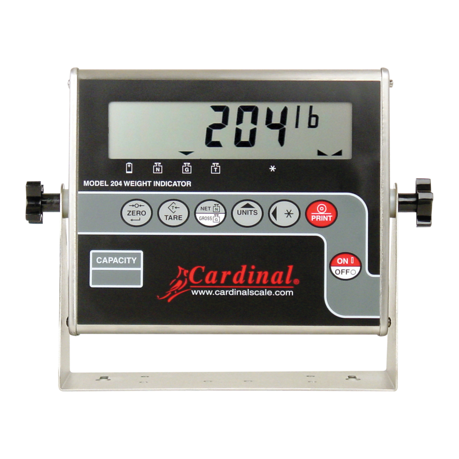
Pounds, kilograms, ounces or grams Keyboard: Membrane type with 7 keys Enclosure Size: 8" W x 6 5/8" H x 2 1/8" D (204 x 168 x 54mm) Enclosure Construction: 304 Stainless Steel Weight: 2.1 lb (without batteries) – 3.1 lb (with batteries) -
Page 6: European Declaration Of Conformity
YY = last two digits of year ZZZ = sequential number The undersigned hereby declares, on behalf of Cardinal Scale Manufacturing Company of Webb City, Missouri, that the above-referenced product, to which this declaration relates, is in conformity with the provisions of:... -
Page 7: Site Preparation Requirements
SITE PREPARATION REQUIREMENTS The Model 204 Weight Indicator is a precision weight indicating instrument. As with any precision instrument, it requires an acceptable environment to operate at its peak performance and reliability. This section is provided to assist you in obtaining such an environment. -
Page 8: Electrical Noise Interference
RFI (Radio Frequency Interference) in a digital weight indicator is weight indication instability during a radio transmission. Cardinal digital weight indicators are designed with special grounding and RFI shielding to achieve a high degree of immunity to common RFI. To maximize the digital weight indicator’s immunity to radio transmissions, follow these guidelines: 1. -
Page 9: Installation
Mounting The Model 204 Weight Indicator may come mounted on a column or it may be mounted on a desktop or other smooth, flat, horizontal surface or it may be mounted on a wall using two (2) #10 screws placed 6.00 inches apart on the wall. - Page 10 Access is via a removable panel on the back of the indicator. The 204 can operate for 200 hours of continuous use when using alkaline batteries or with fully charged Ni-Cad or NiMH batteries, 50 hours of continuous use.
-
Page 11: Battery Installation/Replacement
When the low battery annunciator turns on (and the niCAd setup option is enabled, set to 1 or 2), plug the AC power adapter into the indicator and then into the proper electrical wall outlet. The indicator will begin charging the batteries. 8555-M313-O1 Rev H • 204 Installation & Technical... -
Page 12: Battery Status
NOTE: When the 204 is turned off, the indicator is NOT charging the batteries. Load Cell Connection The load cell cable connects to the 204 via a 9-pin "D" connector on the rear panel of the indicator. Figure No. 4 shows the pin identification for the load cell connector. Make certain that the pins are correctly identified before soldering a wire to them. -
Page 13: Serial Interface Specifications
NOTE: Remove the left end cap to access the jumpers. Refer to Figure No. 9. SERIAL INTERFACE SPECIFICATIONS Your Model 204 has a RS-232 serial port that may be connected to a printer to record weight and associated data or it may be connected to a remote display (like the SB-80) or to a computer for transmission of weight data. -
Page 14: Serial Data Formats
If the Printer Continuous output was not selected, COnt=0 (0=NO) during setup and calibration of the indicator, and the 204 is connected to a computer, it will transmit a single set of weight data each time the computer sends an ENQ (hex 05) or a SMA weight request (W). -
Page 15: Keypad Functions
ON / OFF (I / O) KEY With the indicator off, pressing this key will apply power to the 204 and turn on the display. If the indicator is already on, pressing this key will remove power from the indicator. - Page 16 The (Stable) annunciator is located to the right of the weight display and is turned on when the weight display is stable. When off, it means that the change in successive weight samples is greater than the motion limits selected during setup and calibration of the indicator. 8555-M313-O1 Rev H • 204 Installation & Technical...
- Page 17 Pressing the Θ / key a second time will unlock the display and turn off the annunciator. 8555-M313-O1 Rev H • 204 Installation & Technical...
-
Page 18: Setup And Calibration
204's keyboard. Pressing the PRINT key will cause the data entered or displayed to be retained and the 204 will advance to the next prompt. The cursor location is identified by the blinking character and can be advanced to the left to the next position by pressing the ASTERISK key. - Page 19 3. Determine the exact amount of test weights to be placed on the scale platform and enter this value into the 204 by using the UNITS and ASTERISK keys in the same manner used to enter the scale's capacity. Verify that the numbers entered are the same as the total weight of test weights, and the least significant digit agrees with the scale interval.
- Page 20 SETUP AND CALIBRATION, CONT. USA= (USA - Domestic or International) The display will next indicate USA=. This is the prompt to select whether the 204 is used in the USA (domestic) or outside the US (international). Press the ASTERISK key to show current setting, then press the UNITS key to select 1 (1=YES, Domestic) or 0 (0=NO, International).
- Page 21 The display will next indicate HoLd= which is the prompt for the selection to enable or disable the Hold (ASTERISK) key. This mode of operation will lock the 204 display and is used only in noncommercial applications. Press the ASTERISK key to show the current setting, then press the UNITS key to select 1 (1=YES, enable) or 0 (0=NO, disable).
- Page 22 EOP= (End-Of-Print Line Feeds) The display will now show EoP=. At the end of a data transmission to a printer, the 204 can send a number of line feed commands to space the paper in the printer to the desired position for withdrawal or for the next print.
-
Page 23: Setup Review
SETUP REVIEW The 204 allows several operational parameters to be reviewed and changed as necessary without having to enter the setup and calibration mode. The parameters in the setup review will be processed in the following sequence: Disable battery charging (use Alkaline batteries), Enable battery charging... -
Page 24: Calibration Seal Installation
CALIBRATION SEAL INSTALLATION If your Model 204 Weight Indicator is used in a commercial application it must be tested and sealed by your local weights and measurement official. The 204 is designed to accept a lead and wire security seal to prevent unauthorized access to the calibration adjustments. Refer to the Figure No. -
Page 25: Error And Status Displays
Displayed to indicate the 204 is turning off. BEFORE YOU CALL FOR SERVICE The 204 has been designed to provide you with years of trouble-free operation. In spite of this, troubles sometimes happen. Before calling for service assistance you should make some initial checks to verify that a problem does exist. - Page 26 204 PARTS IDENTIFICATION 8555-M313-O1 Rev H • 204 Installation & Technical...
- Page 27 8555-B310-0A CABLE: SERIAL 8555-B312-0A CABLE: BATTERY 8555-C146-08 DISPLAY STAND 8555-C304-18 REAR PANEL 8555-D301-0A CONTROLLER BOARD 8555-D302-08 KEYPAD 8555-C306-0A FRONT PANEL ASSEMBLY 6800-1045 AC ADAPTER 100-240VAC/12VDC @ 1 AMP NOT SHOWN 8555-M313-O1 Rev H • 204 Installation & Technical...
- Page 28 8555-M313-O1 Rev H • 204 Installation & Technical...
Need help?
Do you have a question about the 204 and is the answer not in the manual?
Questions and answers