Sign In
Upload
Manuals
Brands
YOKOGAWA Manuals
Measuring Instruments
EXAxt ZR Series
YOKOGAWA EXAxt ZR Series Manuals
Manuals and User Guides for YOKOGAWA EXAxt ZR Series. We have
1
YOKOGAWA EXAxt ZR Series manual available for free PDF download: User Manual
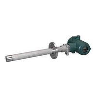
YOKOGAWA EXAxt ZR Series User Manual (169 pages)
Integrated type Zirconia Oxygen/Humidity
Brand:
YOKOGAWA
| Category:
Measuring Instruments
| Size: 4 MB
Table of Contents
Safety Precautions
5
Table of Contents
10
1 Overview
16
Exaxt ZR > System Configuration
16
System 1
16
System 2
17
System 3
18
Exaxt ZR > System Components
19
System Components
19
Oxygen/Humidity Analyzer and Accessories
19
2 Specifications
20
General Specifications
20
Standard Specifications
20
ZR202G Integrated Type Zirconia Oxygen Analyzer
21
ZO21R Probe Protector
28
ZH21B Dust Protector
29
ZA8F Flow Setting Unit and ZR20H Automatic Calibration Unit
30
ZA8F Flow Setting Unit
30
ZR20H Automatic Calibration Unit
33
ZO21S Standard Gas Unit
35
Other Equipment
36
Dust Filter for Oxygen Analyzer (Part No. K9471UA)
36
Dust Guard Protector (K9471UC)
36
Stop Valve (Part No. L9852CB or G7016XH)
37
Check Valve (Part No. K9292DN or K9292DS)
37
Air Set
38
Zero Gas Cylinder (Part No. G7001ZC)
39
Pressure Regulator (G7013XF or G7014XF) for Gas Cylinder
40
Case Assembly (E7044KF) for Calibration Gas Cylinder
40
ZR202A Heater Assembly
41
3 Installation
42
Installation of ZR202G Zirconia Oxygen/Humidity Analyzer
42
Probe Insertion Hole
42
Installation of the Probe
43
Installation of the Dust Filter (K9471UA), Dust Guard Protector (K9471UC) Probe Protector (ZO21R)
43
Installation of ZH21B Dust Protector
45
Installation of ZA8F Flow Setting Unit
46
Installation of ZR20H Automatic Calibration Unit
47
Installation of the Case Assembly (E7044KF) for Calibration Gas Cylinder
48
Insulation Resistance Test
49
4 Piping
52
Piping for System 1
52
Piping Parts for System 1
53
Piping for the Calibration Gas
53
Piping for the Reference Gas
53
Piping Parts for System 2
54
Piping for the Calibration Gas
54
Piping for the Reference Gas
55
Piping for System 3
55
Piping for the Oxygen Analyzer with Pressure Compensation
57
Piping Parts for Oxygen Analyzer with Pressure Compensation
59
Piping for the Calibration Gas
59
Piping for the Reference Gas
59
5 Wiring
60
General
60
Terminals for the External Wiring
61
Wiring
61
Mounting of Cable Gland
62
Wiring for Analog Output
62
Cable Specifications
63
Wiring Procedure
63
Wiring Power and Ground Terminals
63
Wiring for Power Line
63
Wiring for Ground Terminals
64
Wiring for Contact Output
64
Cable Specifications
64
Wiring Procedure
64
Wiring for Contact Input
64
Cable Specifications
65
Wiring Procedure
65
6 Components
66
ZR202G Zirconia Oxygen/Humisity Analyzer
66
ZA8F Flow Setting Unit, ZR20H Automatic Calibration Unit
67
7 Startup
68
Checking Piping and Wiring Connections
68
Valve Setup
68
Supplying Power to Converter
69
Operation of Infrared Switch
69
Display and Switches
69
Display Configuration
71
Entering Parameter Code Selection Display
72
Selecting Parameter Codes
73
Changing Set Values
73
Confirmation of Equipment Type Setting
75
Selection of Measurement Gas
76
Output Range Setting
76
Oxygen Analyzer -Minimum Current (4 Ma) and Maximum Current (20 Ma) Settings
76
Humidity Analyzer -Minimum Current (4 Ma) and Maximum Current (20 Ma) Settings
78
Setting Display Item
79
Oxygen Analyzer - Setting Display Item
79
Humidity Analyzer - Setting Display Item
80
Checking Current Loop
80
Checking Contact I/O
81
Contact Output Check
81
Checking Calibration Contact Output
82
Checking Input Contacts
83
Calibration
83
Calibration Setup
83
Manual Calibration
86
8 Detailed Data Setting
88
Current Output Setting
88
Oxygen Analyzer_Current Output Setting
88
Oxygen Analyzer_Analog Output Setting
88
Concentration at 20 Ma
88
Input Ranges
89
Setting Minimum Oxygen Concentration (at 4 Ma) and Maximum Oxygen Concentration (at 20 Ma)
89
Entering Output Damping Constants
92
Selection of Output Mode
92
Default Values
92
Output Hold Setting
92
Definition of Equipment Status
93
Preference Order of Output Hold Value
94
Output Hold Setting
94
Default Values
94
Setting Alarms
95
Alarm Values
95
Alarm Output Actions
95
Alarm Setting
96
Default Values
97
Output Contact Setup
97
Output Contact
97
Setting Output Contact
98
Default Values
99
Input Contact Settings
99
Input Contact Functions
99
Setting Input Contact
100
Default Values
100
Other Settings
100
Setting the Date-And-Time
100
Setting Periods over Which Average Values Are Calculated and Periods over Which Maximum and Minimum Values Are Monitored
101
Setting Fuels
102
Setting Measurement Gas Temperature and Pressure
106
Setting Purging
107
9 Calibration
108
Calibration Briefs
108
Principle of Measurement with a Zirconia Oxygen Analyzer
108
Measurement Principle of Zirconia Humidity Analyzer
109
Calibration Gas
111
Compensation
111
Characteristic Data from a Sensor Measured During Calibration
112
Calibration Procedures
113
Mode
113
Calibration Procedure
113
Zero Gas Concentration
114
Span Gas Concentration
114
Calibration Time
114
Calibration
116
Manual Calibration
116
Semi-Automatic Calibration
116
Automatic Calibration
117
10 Other Functions
118
Detailed Display
118
Oxygen Concentration
119
Humidity
119
Mixing Ratio
119
Relative Humidity
119
Dew Point
119
Air Ratio
120
Cell Temperature
120
Process Gas Temperature
120
C. J. Temperature
120
Amount of Water Vapor in Exhaust Gas
120
Cell Voltage
121
Thermocouple Voltage
121
Cold Junction Voltage
121
Current Output
121
Response Time
121
Cell's Internal Resistance
122
Robustness of a Cell
122
Heater On-Time Ratio
122
Oxygen Concentration (with Time Constant), Humidity (with Time Constant), and Mixing Ratio (with Time Constant)
123
Maximum Oxygen Concentration, Humidity, and Mixing Ratio
123
Minimum Oxygen Concentration, Humidity, and Mixing Ratio
123
Average Oxygen Concentration, Humidity, and Mixing Ratio
123
Span and Zero Correction Ratios
123
History of Calibration Time
124
Time
124
Software Revision
124
Operational Data Initialization
124
Initialization Procedure
125
Reset
125
Handling of the ZO21S Standard Gas Unit
138
Standard Gas Unit Component Identification
138
Installing Gas Cylinders
138
Calibration Gas Flow
139
Methods of Operating Valves in the ZA8F Flow Setting Unit
140
Preparation before Calibration
141
Operating the Span Gas Flow Setting Valve
141
Operating the Zero Gas Flow Setting Valve
141
Treatment after Calibration
141
11 Inspection and Maintenance
142
Inspection and Maintenance of the Detector
142
Cleaning the Calibration Gas Tube
142
Replacing the Sensor Assembly
143
Replacement of the Heater Assembly
145
Replacement of Dust Filter
147
Replacement of O-Ring
147
Stopping and Re-Starting Operation
148
Inspection and Maintenance of the Converter
148
Fuse Rating
149
Replacement of Flowmeter for ZR20H Automatic Calibration Unit
150
12 Troubleshooting
152
Displays and Measures to Take When Errors Occur
152
What Is an Error
152
Measures to Take When an Error Occurs
153
Displays and Measures to Take When Alarms Are Generated
155
What Is an Alarm
155
Measures Taken When Alarms Are Generated
155
Measures When Measured Value Shows an Error
159
Measured Value Higher (Lower for Humidity Analyzer) than True Value
159
Measured Value Lower (Higher for Humidity Analyzer) than True Value
160
Measurements Sometimes Show Abnormal Values
161
Customer Maintenance Parts List
162
Customer Maintenance Parts List
164
Customer Maintenance Parts List
166
Revision Information
168
Advertisement
Advertisement
Related Products
YOKOGAWA EML500 Series
YOKOGAWA EXAxtZR
YOKOGAWA EXA DO402G
Yokogawa Exaxt450
YOKOGAWA EXAxt 450
YOKOGAWA EXA SC202G
YOKOGAWA EXA SC202S
YOKOGAWA DpharpEJX vigilantplant EJX110
YOKOGAWA DpharpEJX vigilantplant EJX430A
YOKOGAWA Dpharp vigilantplant EJA310A
YOKOGAWA Categories
Measuring Instruments
Test Equipment
Transmitter
Controller
Media Converter
More YOKOGAWA Manuals
Login
Sign In
OR
Sign in with Facebook
Sign in with Google
Upload manual
Upload from disk
Upload from URL