
Subscribe to Our Youtube Channel
Related Manuals for YOKOGAWA ZR802S


Summary of Contents for YOKOGAWA ZR802S
- Page 1 User’s Manual ZR802S Explosion-proof Zirconia Oxygen Analyzer, Converter IM 11M13G01-02EN IM 11M13G01-02EN 1st Edition...
- Page 2 <Introduction> Introduction Thank you for purchasing the ZR802S Explosion-proof Zirconia Oxygen Analyzer, Converter. Please read the following respective documents before installing and using the ZR802S Explosion-proof Zirconia Oxygen Analyzer, Converter. The related documents are as follows. General Specifications Contents Document number...
- Page 3 Description in this manual Model Product Name Specification Installation Operation Maintenance CMPL ZR22S General-purpose detector ZR22S High temperature detector (0.15 m) ZR802S Zirconia Oxygen Analyzer ZO21R Probe protector for ZR22S ZO21P High temperature probe ...
- Page 4 When using either of these instruments in an explosion-susceptible hazardous area, note the following and observe the given precautions: Use only the supplied, the Explosion-proof Zirconia Oxygen Analyzer, Converter (ZR802S) and accessories, or any explosion-proof certification may be invalidated. For the details, refer to the system configurations in the manual.
- Page 5 <Introduction> CAUTION This instrument is tested and certificated as explosion-proof type. Please note that the construction of the instrument, installation, external wiring, maintenance or repair is strictly restricted, and non-observation or negligence of this restriction would result in dangerous condition. NOTICE Specification check When the instrument arrives, unpack the package with care and check that the instrument has...
- Page 6 • No part of the user’s manuals may be transferred or reproduced without prior written consent from YOKOGAWA. • YOKOGAWA reserves the right to make improvements in the user’s manuals and product at any time, without notice or obligation. • If you have any questions, or you find mistakes or omissions in the user’s manuals, please contact our sales representative or your local distributor.
- Page 7 The product is provided on an “as is” basis. YOKOGAWA shall have neither liability nor responsibility to any person or entity with respect to any direct or indirect loss or damage arising from using the product or any defect of the product that YOKOGAWA can not predict in advance. All rights reserved The copyright of the programs and online manuals contained in the software media shall remain with YOKOGAWA.
- Page 8 The ZR802G should only be used with equipment that meets the relevant IEC, American or Canadian standards. Yokogawa accepts no responsibility for the misuse of this unit. Don’t install instruments in the hazardous area. Do not use an abrasive or organic solvent in cleaning the instrument.
- Page 9 The product is provided on an “as is” basis. YOKOGAWA shall have neither liability nor responsibility to any person or entity with respect to any direct or indirect loss or damage arising from using the product or any defect of the product that YOKOGAWA can not predict in advance. Notes on Handling User’s Manuals •...
- Page 10 Batteries are included in this product. This marking indicates they shall be sorted out and collected as ordained in the EU battery Directive/Regulation and UK battery Regulation. When you need to replace batteries, contact your local Yokogawa office in the EEA and/or UK respectively.
- Page 11 Blank Page...
-
Page 12: Table Of Contents
System 1 .................... 1-1 1.1.2 System 2 .................... 1-2 System Components ..................1-2 Specifications ................... 2-1 General Specifications ..................2-1 ZR802S Explosion-proof Zirconia Oxygen Analyzer Converter ....2-2 2.2.1 Standard specification ............... 2-2 2.2.2 Functions.................... 2-7 ZA8F Flow Setting Unit ................... 2-11 Installation .................... - Page 13 Contact Input Wiring ................ 4-11 4.2.9 Pressure Input Wiring ..............4-12 4.2.10 Communication wiring ..............4-13 Components and Their Functions ............5-1 ZR802S Converter ..................... 5-1 Touchpanel Switch Operations ............... 5-2 5.2.1 Home screen and icons ..............5-2 5.2.2 Screen flow ..................5-4 5.2.3...
- Page 14 Toc-3 <CONTENTS> 7.2.1 Definition of Equipment Status ............7-4 7.2.2 Preference Order of Output Hold Value ..........7-5 7.2.3 mA output settings ................7-5 7.2.4 Default Values ..................7-6 Output limit setting ................... 7-6 7.3.1 Action of Output limit setting .............. 7-6 7.3.2 Setting of Output limit .................
- Page 15 Toc-4 <CONTENTS> Calibration ......................8-9 8.3.1 Manual Calibration ................8-9 8.3.2 Semi-automatic Calibration ............... 8-9 8.3.3 Automatic Calibration ................. 8-9 Other Functions ..................9-1 Detailed-data Display ..................9-1 9.1.1 Span correction ratio, Zero correction ratio ........9-1 9.1.2 Cell response time ................9-1 9.1.3 Cell robustness ..................
- Page 16 Toc-5 <CONTENTS> 9.5.2 Operation of Blow back ..............9-12 9.5.3 Setting Output Hold Time and Blow back Time ....... 9-13 9.5.4 Setting Interval, Start Date, and Start Time ........9-13 9.5.5 Default Setting.................. 9-14 Simple cell resistance measurement ............9-14 9.6.1 MODE ....................
- Page 17 Blank Page...
-
Page 18: Overview
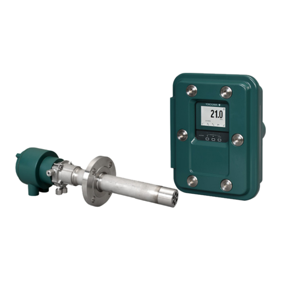
<1. Overview> Overview The ZR802S converter uses a digital display, displays the cell temperature and cell emf in addition to the oxygen concentration and includes a Human Machine Interface (HMI), that offers easy touch panel operation. This analyzer is most suitable for monitoring combustion and controlling the low-oxygen combustion of various industrial furnaces in explosive atmosphere at petroleum refinery, petrochemical plant, and natural gas plant. -
Page 19: System 2
“combustible gas detected” contact input turns off power to the heater. There’s also contact output from the converter that can be used to operate a purge gas valve to supply air to the sensor. ZR802S Converter ZR22S Explosion-proof Zirconia Hazardous Area... - Page 20 <1. Overview> Detector Components Sample gas temperature 0 to 700ºC Sample gas temperature 700 to 1400ºC Insertion Application High temperature detector Application Mounting General use Probe length Sample Detector Heating outlet (ZR22S) furnace Absorption structure High temperature detector Probe adapter for high Boiler (ZR22S) temperature use...
- Page 21 Blank Page...
-
Page 22: Specifications
<2. Specifications> Specifications This chapter describes the specifications for the following: ZR802S Zirconia Oxygen Converter (See Section 2.2) ZA8F Flow Setting Unit (See Section 2.3) CAUTION Oxygen concentration of sample/reference /calibration gas shall not exceed that found in normal air, typically 21 vol%. -
Page 23: Zr802S Explosion-Proof Zirconia Oxygen Analyzer Converter
REACH Regulation EC 1907/2006 Information of the WEEE Directive This product is purposely designed to be used in a large scale fixed installations only and, therefore, is out of scope of the WEEE Directive. The WEEE Directive is only valid in the EU and UK. ZR802S Explosion-proof Zirconia Oxygen Analyzer Converter 2.2.1 Standard specification Display: LCD color display of size 320 by 240 dot with touchscreen Operation: Touch screen operation when the door is open. - Page 24 <2. Specifications> Digital Communication: HART7; AO1, 250 to 550 Ω Ethernet (Modbus TCP); 10/100 Mbps, Cable length Max.100 m, grounding the shield RS-485 (Modbus RTU); 115200/38400/9600 bps, Cable length Max.600 m (115200 bps) Max.1200 m (38400/9600 bps) grounding the shield Contact Output: Number of points;...
- Page 25 Mint green (equivalent to RAL 190 30 15) Finish: Polyurethane corrosion-resistance coating Weight: Approx. 16 kg ■ Explosion-proof Approval Explosion-proof approval Integrated type of major standards and Detector (ZR22S) Converter (ZR802S) (ZR202S) directives ATEX: EN IEC 60079-0 EN IEC 60079-0 EN 60079-1 EN 60079-1 Applicable Standard: EN 60079-31...
- Page 26 <2. Specifications> Explosion-proof approval Integrated type of major standards and Detector (ZR22S) Converter (ZR802S) (ZR202S) directives ANSI/UL 60079-0 ANSI/UL 60079-1 ANSI/UL 60079-31 ANSI/UL 61010-1 Applicable Standard ANSI/UL 61010-2-30 ANSI/UL 50E NEMA 250 Not applied ANSI/IEC 60529 Class I, Zone 1, AEx db IIC T6 Gb Type of protection: Zone 21 AEx tb IIIC T85ºC Db...
- Page 27 <2. Specifications> Explosion-proof approval Integrated type and registration in specific Detector (ZR22S) Converter (ZR802S) (ZR202S) countries UKEX: EN IEC 60079-0 EN 60079-1 Applicable Standard: EN 60079-31 EN 60529+A1+A2 II 2 G Ex db IIC T6 Gb Type of protection: Not applied II 2 D Ex tb IIIC T85ºC Db...
-
Page 28: Functions
<2. Specifications> 2.2.2 Functions Display Functions: Value Display; Displays values of the measured oxygen concentration, etc Graph Display; Displays trends of measured oxygen concentration and the test result from a cell resistance tester. Data Display; Displays various useful data for maintenance, such as cell temperature, reference junction temperature, maximum/minimum oxygen concentration, or the like Status Message;... - Page 29 <2. Specifications> NAMUR NE 107 Alarm Display Function: Displays 4 warnings of NAMUR NE 107 standard; F: Failure (Fault equivalent, Power supply to the heater shuts down.) C: Function Check S: Out of Specification M: Maintenance Required Data Logging Function: Stores following data to SD card or visualizes on the instrument display. SD cards which are recommended or equivalent must be supplied by customer, Event display;...
- Page 30 Suffix code Option code Description ZR802S - - - - - - - - - - - - - - - - - - - - - - - - - - - - - - Explosion-proof Zirconia Oxygen Analyzer, Converter...
- Page 31 2-10 <2. Specifications> Language English, Chinese, German, French, Portuguese, Japanese SD card (supplied by customer) Item Q'ty Parts No. Description SD card 773001 1 GB Customer may provide. 128 MB or above SD or SDHC External Dimensions Unit : mm 2B mounting pipe 4 - Ø6.5 for Wall mounting 56.8...
-
Page 32: Za8F Flow Setting Unit
Calibration Gas (zero gas, span gas) Consumption: Approx. 0.7 L/min (at calibration time only) Weight: Approx. 2.3 kg NOTE Use instrument air for span calibration gas, if no instrument air is available, contact YOKOGAWA. Model and Codes Model Suffix code Option code... - Page 33 2-12 <2. Specifications> External Dimensions Unit : mm ø6 Hole REFERENCE CHECK JIS 50A (60.5mm) REFERENCE SPAN ZERO mounting pipe 235.8 222.8 Calibration gas outlet Span gas inlet Reference gas outlet Zero gas inlet Piping connection port A CHECK SPAN ZERO Model Piping connection port A ZA8F-J*C...
-
Page 34: Installation
<3. Installation> Installation This chapter describes installation of the following equipment: Section 3.1 Installation of the ZR802S Converter Section 3.2 Installation of ZA8F Flow Setting Unit Section 3.3 Insulation Resistance Test CAUTION Oxygen concentration of sample/reference /calibration gas shall not exceed that found in normal air, typically 21 vol%. -
Page 35: Installation Of Za8F Flow Setting Unit
<3. Installation> <Wall Mounting> (1) Drill mounting holes through the wall as shown in Figure 3.2. 4 - ø10 hole Wall mount hole Figure 3.2 Mounting holes Figure 3.3 Wall Mounting (2) Mount the converter. Secure the converter on the wall using four screws. Note: For wall mounting, the bracket and bolts are not used. -
Page 36: Insulation Resistance Test
<3. Installation> F03-13E.ai Figure 3.4 Pipe Mounting <Wall Mounting> (1) Make a hole in the wall as illustrated in Figure 3.5. (2) Mount the flow setting unit. Remove the pipe mounting parts from the mount fittings of the flow setting unit and attach the unit securely on the wall with four screws. Unit : mm 4 - Ø6.5 hole, or M5 screw F03-14E.ai... - Page 37 (5) Contact input terminal/sensor input terminal is isolated, but Insulation Resistance testing is abort because the voltage of the surge protection arrester between the terminal and ground is low. (6) After completing all tests, put back the wiring in place. Insulation ZR802S Converter ZR22S Detector resistance tester crossover wiring CELL...
-
Page 38: Wiring
<4. Wiring> Wiring In this Chapter, the wiring necessary for connection to the ZR22S/ZR802S Explosionproof Zirconia Oxygen Analyzer is described. General WARNING NEVER supply current to the converter or any other device constituting a power circuit in combination with the converter, until all wiring is completed. - Page 39 ZR802S and the connected device on the other side. If there is no potential difference between the ZR802S and the device on the other side, it may be more effective to connect to the ground on both sides.
-
Page 40: Terminals For The External Wiring In The Converter
<4. Wiring> 4.1.1 Terminals for the External Wiring in the Converter Open the front door and remove the terminal covering plate to gain access to the converter external wiring terminals CAUTION After wiring necessary cable to the converter terminals, be sure to fix the terminal covering plate with two screws again. -
Page 41: Wirings
(4) Power and ground (5) Contact output (6) Operation of the solenoid valve of automatic calibration unit (7) Contact input (8) Pressure input (9) RS485 or Ethernet ZR22S Explosion-proof Zirconia Oxygen ZR802S Analyzer, Detecter Explosion-proof Zirconia Oxygen Analyzer Ethernet RS485 RS-485 Ether Termination... -
Page 42: Mounting Of Cable Gland
ISO M20x1.5: F9480ZA Figure 4.4 Cable gland mounting <Conduit> For ZR802S-B or ZR802S-C, seal all conduits within 18 inches of the enclosure. Refer to user’s manual for detectors to install the conduit on the detectors. 18 inch (475 mm) MAX. Non-hazardous Area... -
Page 43: Wiring
<4. Wiring> Wiring 4.2.1 Connection to Converter To connect the wiring to the converter, proceed as follows: (1) M4 screws are used for the terminals of the converter. Each cable should be terminated in the corresponding size crimp-on terminals. (2) When a rubber insulated glass braided wire is used for wiring to the detector, use a terminal box. -
Page 44: Power And Grounding Wiring
(2) The size of converter terminal screw threads is M4. Each cable should be terminated corresponding to crimp-on terminals. Grounding to the ground terminal on the converter and Detector out side Crimp-on terminal of Converter case the ground wire ZR802S ZR22S Converter Detector FG terminal Spring washer (M4 screw) -
Page 45: Wiring For Power To Detector Heater
4.2.4 Wiring for Power to Detector Heater This wiring provides electric power from the converter to the heater for heating the sensor in the detector. (1) Ambient temperature of the detector: 75°C or less ZR802S ZR22S Converter Detector HTR 7 HTR 8 (2) Ambient temperature of the detector: exceeding 75°C... -
Page 46: Wiring For Detector Output
<4. Wiring> 4.2.5 Wiring for Detector Output This wiring enables the converter to receive cell output from the detector, output from a thermocouple and a reference junction compensation signal. Install wires that allow for 10 Ω of loop resistance or less. Keep detector wiring away from power wiring. (1) Ambient temperature of the detector: 75°C or less Converter Detector... -
Page 47: Wiring For Analog Output
4.2.6 Wiring for Analog Output This wiring is for transmitting 4 to 20 mA DC output signals to a device, e.g. recorder. Maintain the load resistance including the wiring resistance at 550 Ω or less. ZR802S Converter Receiver 1 AO-1(+) -
Page 48: Contact Output Wiring
The converter has up to 4 contact outputs. The contact outputs 1 to 3 can be freely assigned to “low limit alarm”, “high limit alarm”, etc. user selectable, but the assignment of contact output 4 is fixed (“fault output”). When using these contact outputs, install the wiring as follows: ZR802S Terminal box Annunciator or the like Converter... -
Page 49: Pressure Input Wiring
4-12 <4. Wiring> Wiring Procedure (1) M4 screws are used for the terminals of the converter. Each cable should be terminated with crimp-on terminals that fit M4 screw. (2) The ON/OFF level of this contact input is identified by the resistance or voltage. Connect a contact input that satisfies the specifications in Table 4.2. -
Page 50: Communication Wiring
<4. Wiring> 4.2.10 Communication wiring ZR802S wired digital communication can be Ethernet(Modbus TCP) or RS-485 (Modbus RTU) depending on your requirements. Be sure to use shielded cables to prevent malfunction due to external noise ad to avoid the effects of radiated noise from ZR802S on other equipment. - Page 51 4-14 <4. Wiring> Ethernet cable Use Ethernet cable when the digital communication code -E (Modbus TCP) is selected. RJ45 connectors are provided in the positions shown in Figure 4.18. Insert a Category 5 or higher STP cable (shielded cable) into RJ45 connector. Both straight and cross connection is available for cable connection.
-
Page 52: Components And Their Functions
Components and Their Functions In this Chapter, the names and functions of components are described for the major equipment of the ZR Explosion-proof Zirconia Oxygen Analyzer. ZR802S Converter Operation panel ● LCD touch panel (Infrared touch display when the front cover is closed) ●... -
Page 53: Touchpanel Switch Operations
Touchpanel Switch Operations 5.2.1 Home screen and icons ZR802S adopts touch panel type which is operated by pressing the display. Figure 5.1 shows the home screen. Icons displayed on the screen depend on setup and device status. Tag name Converter menu... - Page 54 <5. Components and Their Functions> Alarm icon Display area: Alarm icon is displayed here. Press the area that the icon indicates to see the description of each alarm. Fault icon Alarm icon See Section “9.4.2 NE107 mode”. Status Display icon area: Icons are displayed depending on the device status.
-
Page 55: Screen Flow
<5. Components and Their Functions> 5.2.2 Screen flow Figure 5.6 shows the screen flow chart. You can move to each setting, execution or confirmation screen from “Converter menu”, “Sensor menu” on Home screen. [Home] returns to Home screen from any screen. Short cut Calibration Home screen... -
Page 56: Functions On Screens
<5. Components and Their Functions> 5.2.3 Functions on screens (1) Home screen: Displays three value of each selected item. See Section “7.9 Setting Display Item”. Icons are displayed to indicate alarm or status of the device. (2) Converter menu: Calibration, Maintenance, Setting and other items are displayed. (3) Sensor menu: This allows you to view such detailed data as the cell (sensor) electromotive force, cell (sensor) temperature etc..See Section “9.1... -
Page 57: Infrared Switch Operations
5.3.1 Display and Infrared Switch ZR802S adopts infrared switch enabling operations while the cover being closed. At the startup, the infrared switch is disabled. By enabling it, the infrared switch can be used. Refer to “5.3.2 How to enable/disable infrared switch” to enable the function. -
Page 58: How To Enable/Disable Infrared Switch
<5. Components and Their Functions> Press finger firmly on the glass surface of the switch to operate the infrared switch. To press the same switch two times in a row, press it once then lift your finger from the glass surface before repeating the press for the second time. -
Page 59: Za8F Flow Setting Unit
<5. Components and Their Functions> ZA8F Flow Setting Unit Reference gas flow setting valve Span gas flow setting valve Zero gas flow setting valve Flowmeter for reference gas Flowmeter for calibration gas F06-8E.ai Figure 5.10 ZA8F Flow Setting Unit IM 11M13G01-02E... -
Page 60: Startup
<6. Startup> Startup The following describes the minimum operating requirements — from supplying power to the converter to analog output confirmation to manual calibration. Startup Procedure The startup procedure is as follows: Check settings Check piping & wiring Check valve type setting Permanent power wiring Start set parameters Warmup, then calibrate... -
Page 61: Supplying Power To The Converter
<6. Startup> Supplying Power to the Converter CAUTION To avoid temperature changes around the detector, it is recommended that (rather than turning it on and off) power be continuously supplied to the Oxygen Analyzer if it is used in an application where it is used periodically. -
Page 62: Confirmation Of Converter Type Setting
<6. Startup> Confirmation of Converter Type Setting This converter can be used for an oxygen analyzer. Before setting the operating data, be sure to check that the desired converter model has been set. CAUTION If the converter type setting is changed, the operating data that have been set are initialized and the default settings remain. -
Page 63: Confirmation Of Detector Type Setting
<6. Startup> Confirmation of Detector Type Setting (1) Press the [Sensor menu] key. (2) Select [Setting] > [Setting]. (3) Confirm ZR22 (PT1000:Ohm) is selected as detector. Factory default is ZR22. (4) If [ZS8D/ZO21DW] is preset, press [Selection of detector] to set [ZR22]. Figure 6.5 Selection of detector CAUTION... -
Page 64: Output Range Setting
<6. Startup> Figure 6.6 Choice of moisture base Output Range Setting This section sets forth analog output range settings. For details, consult Section “8.1 Current Output Setting”, later in this manual. Minimum Current (4 mA) and Maximum Current (20 mA) Settings To set the minimum and maximum current settings, follow these steps: (1) Select the “Setting”... -
Page 65: Setting Display Item
<6. Startup> Setting Display Item This section briefly describes the Home screen item shown in Figure 6.87 1st item 2nd item 3rd item Figure 6.8 Home screen (1) [Converter menu] > [Maintenance] (2) Select the “Display settings”. (3) Select “Display item”. Select “1st display item” selection. A window opens to select an item to display. - Page 66 <6. Startup> Table 6.1 Display Items 1st display 2nd, 3rd Item Display item display item Oxygen ○ ○ Oxygen concentration during measurement concentration ○ Air ratio Current computed air ratio ○ Moisture content Moisture content (%H O) in the exhaust gas ○...
- Page 67 <6. Startup> About moisture content: The moisture content in the exhaust gas is calculated based on the parameters of the fuel setting (refer to Section “8.7.3 Setting Fuels”). The moisture content may be expressed mathematically Moisture content = {(water vapor content per fuel unit quantity) + (water content in air)}/ total amount of exhaust gas = { Gw + ( 1.61 ...
-
Page 68: 6.10 Checking Current Loop
<6. Startup> 6.10 Checking Current Loop The set current can be output as an analog output. (1) “Converter menu” > “Maintenance” (2) Select “Loop check setting”. (3) Set AO1 test output, AO2 test output on “Loop check setting”. (4) Select “Test validity AO1/AO2”. Check an item to enable. Press the save icon to store the data. - Page 69 6-10 <6. Startup> Contact output check CAUTION If you conduct an open-close check for contact output 4, Alarm 016 or Alarm 017 will occur. This is because the built-in heater power of the detector, which is connected to contact output 4, is turned off during the above check.
-
Page 70: 6.11.2 Checking Calibration Contact Output
6-11 <6. Startup> 6.11.2 Checking Calibration Contact Output The calibration contacts are used for solenoid valve drive signals for Automatic Calibration Unit. When using Automatic Calibration Unit, use the calibration contact output to check that the wiring connections have been properly completed and check equipment operation. (1) “Converter menu”... -
Page 71: 6.12 Calibration
6-12 <6. Startup> 6.12 Calibration To calibrate this instrument, the procedure is to measure zero gas and span gas and set the instrument to read the known concentrations. The procedure for both zero and span calibration, or for either zero or span calibration, can be performed manually from the touch display, or can be performed semi-automatically using contact signal inputs to start calibration, (allowing preset calibration and stabilization times), or it can be performed automatically at preset intervals. -
Page 72: 6.12.2 Manual Calibration
6-13 <6. Startup> CAUTION • If instrument air is used for the span gas, dehumidify to a dew point of -20°C or less to remove oil mist and dust before use. • Insufficient dehumidification or use of dirty air may affect measurement accuracy. 6.12.2 Manual Calibration Preparing for calibration Implementation Before performing manual calibration, be sure that the ZA8F Flow Setting Unit zero gas flow... - Page 73 6-14 <6. Startup> Figure 6.17 Span gas Flow Display (4) Selecting “Start calibration” displays the trend graph of the oxygen concentration being measured (Figure 6.18) on screen. Wait for the reading to stabilize around 21% by monitoring the graph and the sensor electromotive force. At this point, calibration is not yet executed.
- Page 74 6-15 <6. Startup> Figure 6.20 Zero gas concentration check (7) Follow the instructions in the display as in Figure 6.21 to turn on the zero gas flow. Open the zero gas flow valve for the Flow Setting Unit and adjust that valve to obtain a flow of 600 ±...
- Page 75 6-16 <6. Startup> Figure 6.23 Zero Calibration complete (10) Select “End”. An oxygen concentration trend graph (with the oxygen concentration being measured) appears and HOLD TIME flashes. This time is referred to as the output- stabilization time. If the HOLD TIME has been set in “Output hold setting”, the analog output remains held. See Section “8.2 Output Hold Setting”...
-
Page 76: Detailed Data Setting
<7. Detailed Data Setting> Detailed Data Setting Current Output Setting This section describes setting of the analog output range. 7.1.1 Setting Minimum Current (4 mA) and Maximum Current (20 mA) (1) “Converter menu” > “Setting” (2) Select the “mA output settings”. (3) Select “mA output1”. -
Page 77: Setting Output Smoothing Factor
<7. Detailed Data Setting> Ranges over which oxygen concentrations can be set Outside ranges Minimum oxygen concentration, vol%O (for a minimum current of 4 mA) F8.0E.ai Minimum-Maximum setting range of oxygen concentration Figure 7.1 7.1.3 Setting Output Smoothing Factor If the measured value changes suddenly, using this measured value as a control may cause harm such as frequent on-off operation. -
Page 78: Selection Of Output Mode
<7. Detailed Data Setting> 7.1.4 Selection of Output Mode You can select whether the relationship between the sample oxygen concentration and the analog output signal be linear or logarithmic. Press the [Output characteristic selections] in the output mode display. A linear/ logarithmic selection display then appears. Select the desired mode. -
Page 79: Output Hold Setting
<7. Detailed Data Setting> Output Hold Setting The “output hold” functions hold an analog output signal at a preset value during the equipment’s warm-up time or calibration or if an error arises. Outputs 1 and 2 can not be set individually. Table 7.2 shows the analog outputs that can be retained and the individual states. -
Page 80: Preference Order Of Output Hold Value
<7. Detailed Data Setting> (4) During Blow back (see Section “9.5 Blow Back”) During semi-automatic blow back: “During semi-automatic blow back” is the time required after pressing the [Blow back start] key, by using the touchpanel or entering a blow back start instruction by using a contact input, until the blow back time and Hold time (output stabilization) elapse. -
Page 81: Default Values
<7. Detailed Data Setting> 7.2.4 Default Values When the analyzer is delivered, or if data are initialized, output hold setting is the default as shown in Table 7.4. Table 7.4 Output Hold Default Values Status Output hold setting Preset value Warm-up mode 4 mA 3.4 mA... -
Page 82: Alarm Setting
<7. Detailed Data Setting> Alarm Setting The analyzer enables the setting of four alarms — high-high, high, low, and low-low alarms — depending upon the measurement conditions. In addition, You can set calibration coefficient alarm, temperature / pressure input alarm, simple cell resistance alarm, etc. The following section sets out the alarm operations and setting procedures. -
Page 83: Alarm Output Actions
<7. Detailed Data Setting> 7.4.3 Alarm Output Actions If the measured values of the oxygen concentration fluctuate between normal (steady state) values and the alarm setting, alarm outputs may be frequently issued and canceled. To avoid this, set the alarm delay and hysteresis for alarm canceling under the alarm output conditions, as Figure 7.5 shows. -
Page 84: Alarm Setting Procedure
<7. Detailed Data Setting> 7.4.4 Alarm Setting Procedure (1) “Converter menu” > “Setting” (2) Select “Alarm setting”. Figure 7.6 Alarm setting • To set the hysteresis (3) Select “Hysteresis” in the Alarm setting display. The numeric-data entry display then appears. Enter the desired hysteresis value. •... -
Page 85: Default Values
7-10 <7. Detailed Data Setting> 7.4.5 Default Values When the analyzer is delivered, or if data are initialized, the default alarm set values are as shown in Table 7.6. Table 7.6 Alarm Setting Default Values Set item Oxygen concentration Setting range Default setting Hysteresis 0 to 9.9 vol%O... -
Page 86: Output Contact Setup
7-11 <7. Detailed Data Setting> Output Contact Setup 7.5.1 Output Contact Mechanical relays provide contact outputs. Be sure to observe relay contact ratings. (For details, see Section “2.1 General Specifications”) The operation modes of each contact output are as follows. For output contacts 1 to 3 you can select open or closed contact when the contact is “operated.”... - Page 87 7-12 <7. Detailed Data Setting> CAUTION The function of Contact output 4 is fixed as an fault only and fixed as “close during operation”. The setting cannot be changed. Table 7.9 Output Contact Settings Item to be selected Description (HH) high-high alarm If “High-High alarm ON”...
-
Page 88: Default Values
7-13 <7. Detailed Data Setting> 7.5.3 Default Values When the analyzer is delivered, or if data are initialized, alarm and other setting defaults are as shown in Table 7.10. Table 7.10 Output Contact Default Settings Item to be selected Contact Contact Contact Contact... -
Page 89: Input Contact Settings
7-14 <7. Detailed Data Setting> Input Contact Settings 7.6.1 Input Contact Functions The converter input contacts execute set functions by accepting a remote dry-contact (“voltage- free contact”) signal. Table 7.11 shows the functions executed by a remote contact signal. Table 7.11 Input Contact Functions Item Function... -
Page 90: Setting Contact
7-15 <7. Detailed Data Setting> 7.6.2 Setting contact (1) “Converter menu” > “Setting” (2) Select “Contact setting”. (3) Select “Contact input” and select the contact open or closed, and the function. Figure 7.9 Contact input setting 7.6.3 Default Values All contact inputs are set to “Disabled” and “Closed” prior factory shipment or after data initialization. -
Page 91: Other Settings
7-16 <7. Detailed Data Setting> Other Settings 7.7.1 Setting the Date-and-Time The following describe how to set the date-and-time. Automatic calibration or blow back works following this setting. Proceed as follows: (1) “Converter menu” > “Others” (2) Select “Date/Time setting”. (3) Input date and time. -
Page 92: Setting Fuels
7-17 <7. Detailed Data Setting> Figure 7.11 Setting the monitoring time of average/max.min. value 7.7.3 Setting Fuels Input Parameters The analyzer calculates the moisture content contained in exhaust gases. The following sets forth the fuel parameters necessary for calculation and their entries. The moisture content may be mathematically expressed by: (water vapor caused by combustion and water vapor contained in the exhaust gas) + (water vapor contained in air for combustion) - Page 93 7-18 <7. Detailed Data Setting> For liquid fuel Amount of water vapor in exhaust gas (Gw) = (1/100) {1.24 (9h + w)} (m /kg) Theoretical amount of air (Ao) = 12.38 x (Hl/10000) – 1.36 (m /kg) Low calorific power = Hl X value = (3.37 / 10000) x Hx –...
- Page 94 7-19 <7. Detailed Data Setting> 0.046 0.044 0.042 0.040 0.038 0.036 0.034 0.032 0.030 0.028 Wet-bulb 0.026 Absolute temperature, °C humidity, kg/kg 0.024 0.022 0.020 0.018 0.016 0.014 0.012 0.010 0.008 0.006 0.004 0.002 0.000 12 14 16 18 20 22 24 26 28 30 32 34 36 38 40 Dry-bulb temperature, °C...
- Page 95 7-20 <7. Detailed Data Setting> Table 7.12 Fuel Data • For liquid fuel Fuel Chemical component Amount of combustion Calorific power Theoretical Specific properties amount of (weight percentage) gas Nm kJ/kg weight value air for kg/l combustion Type Higher Lower Total O SO content...
-
Page 96: Setting Measurement Gas Pressure
7-21 <7. Detailed Data Setting> Procedure (1) “Sensor menu” > “Setting”. (2) Select “Fuel setup”. (3) Enter numerical value on “Exhaust water vapor content”, “Theoretical air volume” “X value”, “Absolute humidity of outside air”. Figure 7.14 Fuel Setup Default Values When the analyzer is delivered, or if data are initialized, default, parameter settings are as shown in Table 7.13. - Page 97 7-22 <7. Detailed Data Setting> When External input is selected (6) When “External input” is selected on “Pressure input selection”, Enter the values of pressure of 4 mA point and 20 mA point respectively of a pressure transmitter you use. (7) When alarm from sample gas pressure is used, select “Pressure upper limit alarm value”, “Pressure lower limit alarm value.”...
-
Page 98: Setting Purging
7-23 <7. Detailed Data Setting> 7.7.5 Setting Purging Purging is to remove condensed water in the calibration gas pipe by supplying a span calibration gas for a given length of time before warm-up of the detector. This prevents cell breakage during calibration due to condensed water in the pipe. - Page 99 7-24 <7. Detailed Data Setting> Figure 7.17 Passwords Display <Default setting> The passwords are not set as shipped from factory. If you reset data, the password settings are deleted. CAUTION If you setup a password, write down the password so you won’t forget it. You are asked for the password when entering a protected operation, such as “Setting”...
-
Page 100: Calibration
<8. Calibration> Calibration Calibration Briefs 8.1.1 Principle of Measurement with a zirconia oxygen analyzer This section sets forth the principles of measurement with a zirconia oxygen analyzer before detailing calibration. A solid electrolyte such as zirconia allows the conductivity of oxygen ions at high temperatures. Therefore, when a zirconia-plated element with platinum electrodes on both sides is heated up in contact with gases having different oxygen partial pressures on each side, the element shows the action of the concentration cell. -
Page 101: Calibration Gas
<8. Calibration> 0.51 vol% O ,81.92mV(Zero origin of calibration) Cell voltage (mV) 21.0 vol% O , 0mV (Span origin of calibration) 21.0 Oxygen concentration (vol % O F9.1E.EPS Figure 8.1 Oxygen concentration in a Sample Gas vs Cell Voltage (21 vol%O Equivalent) The measurement principles of a zirconia oxygen analyzer have been described above. -
Page 102: Compensation
<8. Calibration> 8.1.3 Compensation The deviation of a measured value from the theoretical cell electromotive force is checked by the method in Figure 8.2 or Figure 8.3. Figure 8.2 shows a two-point calibration using two gases: zero and span. Cell electromotive forces for a span gas with an oxygen concentration p1 and a zero gas with an oxygen concentration p2 are measured while determining the calibration curve passing between these two points. -
Page 103: Characteristic Data From A Sensor Measured During Calibration
<8. Calibration> 8.1.4 Characteristic Data from a Sensor Measured During Calibration In addition to calibration data, the following data is collected during calibration to determine the status of the sensors. However, if calibration is not performed correctly (e.g. semi-automatic calibration, an error occurs when it is automatic calibration), these data in this calibration will not be collected. -
Page 104: Calibration Procedures
<8. Calibration> Calibration Procedures NOTE Calibration should be made under normal operating conditions (if the probe is connected to a furnace, the analyzer will undergo calibration under the operating conditions of the furnace). To make a precise calibration, conduct both zero and span calibrations. The following sets forth the required calibration settings: 8.2.1 Mode... -
Page 105: Calibration Procedure
<8. Calibration> 8.2.2 Calibration procedure Select one among Calibration of both span and zero, Calibration of only span, Calibration of only zero. Normally select “span-zero.” 8.2.3 Zero gas Concentration Set the oxygen concentration for zero-point calibration. Enter the oxygen concentration for the zero gas in the cylinder used in the following procedures: Select “Zero gas concentration”... - Page 106 <8. Calibration> Calibration start (contact or switch input) Span calibration Calibration time (span gas valve open) Zero calibration Calibration time (zero gas valve open) Analog output status Hold (output stabilization) time Analog output remains held (when output remains held) F9.6E.ai Figure 8.5 Calibration and Hold Time Settings •...
-
Page 107: Default Values
<8. Calibration> 8.2.6 Default Values When the analyzer is delivered, or if data are initialized, the calibration settings are by default, as shown in Table 8.1. Table 8.1 Default Settings for Calibration Item Default Setting Calibration mode Manual Automatic calibration procedure Span and Zero Zero gas concentration 1.00%O... -
Page 108: Calibration
<8. Calibration> Calibration 8.3.1 Manual Calibration For manual calibration, consult Section “6.12 Calibration”, earlier in this manual. 8.3.2 Semi-automatic Calibration By the touch panel (1) Press[set up] on Home screen to enter a calibration screen. Select “Span” of “Semi-auto calibration”. Only the procedure setting established at “8.2.2 Calibration procedure” is enabled. - Page 109 Blank Page...
-
Page 110: Other Functions
<9. Other Functions> Other Functions Detailed-data Display “Sensor menu” > “Detail” This section describes each data of sensors. Figure 9.1 Detailed-data Display 9.1.1 Span correction ratio, Zero correction ratio These are used to check for degradation of the sensor (cell). If the correction ratio is beyond the limits as shown in Figure 9.2, the sensor should no longer be used. -
Page 111: Cell Robustness
The maximum C. J. temperature varies depending on the type of detector. When ZR802S /CJ is selected, this shows a temperature near terminal box inside a converter case. 9.1.6 Measurement gas press. -
Page 112: Cell Voltage
<9. Other Functions> 9.1.7 Cell voltage The cell (sensor) voltage will be an index to determine the amount of degradation of the sensor. The cell voltage corresponds to the oxygen concentration currently being measured. If the indicated voltage approximates the ideal value (corresponding to the measured oxygen concentration), the sensor will be assumed to be normal. -
Page 113: Pwr. Supply Voltage Mode
<9. Other Functions> 9.1.13 Pwr. supply voltage mode For the best control of the detector’s heater, the control parameters are automatically configured by power supply voltage and frequency. When the power voltage supplied to this instrument is lower than 165 V, “100V”, is indicated. When it is over 165V, “200V” is indicated. 9.1.14 Power frequency mode When the power frequency supplied to the instrument is lower than 55 Hz, “50 Hz”... -
Page 114: Analog Output
<9. Other Functions> 9.2.1 Analog output Displays Analog output1, Analog output2 on graphs with the unit (mA). Figure 9.5 Analog output 9.2.2 Contact output Displays the status of contact output from DO1 to DO4. When the contact is active, ON, not active, OFF is lit on. -
Page 115: Measurement Info
<9. Other Functions> 9.2.4 Measurement info Displays average, maximum, minimum value of measurement. Maximum and minimum value show the date when the measurement is conducted. Setup the monitoring hour value of average/ max. min according to the setting described in 8.6.2. Figure 9.8 Measurement info 9.2.5... -
Page 116: Trend Graph
<9. Other Functions> Figure 9.10 Log information Changing HMI setting of Logbook configuration You can change what to display on the Log information. (1) “Converter menu” > “Maintenance” > “Display setting” > “other settings” (2) Select “Logbook settings”. Check items to change. You can see Cell resistance of zero calibration in “Calibration history”, power ON/Firm update/Operator ID in “Other”. -
Page 117: Simple Cell Resistance Trend
<9. Other Functions> Table 9.3 Trend graph setting selectable item Description Oxygen concentration The graph shows the oxygen concentration during measurement. Output item 1 The graph shows the item select as Output item 1. If this equipment is for the oxygen analyzer, the trend graph will be an oxygen concentration graph. -
Page 118: Other Functions Of Displays
<9. Other Functions> Trend displays only one data per day and the value measured at the earliest time of the day. The horizontal axis is static in six months. You can check the trend for another half year by pressing display switch. -
Page 119: Ne107 Mode
9-10 <9. Other Functions> Figure 9.15 Other settings Display 9.4.2 NE107 mode You can change the alarm display according to the NAMUR NE 107. (1) "Converter" > "Maintenance" > "Display setting" > "Others setting" (2) Select NE107 Mode. Select ON/Off. Table 9.4 NE107 - Off Icon... -
Page 120: Entering Tag Names
When the language is changed, the trend data of the trend screen is cleared. 9.4.7 Unit You cannot change the unit displayed on the screen. If you need to change the temperature to °F, the pressure to psi, please contact Yokogawa. IM 11M13G01-02EN... -
Page 121: Blow Back
9-12 <9. Other Functions> Blow Back This section explains the parameter settings for performing blow back. 9.5.1 Mode There are three modes of blow back operation: no function, semi-automatic, and automatic. Blow back is not performed when the mode is set to “No function”. In “Semi_Auto” mode, blow back can be started by key operation on the display or by a contact input signal, and then sequentially performed at a preset blow back time and hold time. -
Page 122: Setting Output Hold Time And Blow Back Time
9-13 <9. Other Functions> 9.5.3 Setting Output Hold Time and Blow back Time If the blow back mode is in “No function”, the output “Hold time” and “Blow back time” are not displayed. If you select “Hold time”, the numeric-data entry display appears. Enter the desired “Hold time”... -
Page 123: Default Setting
9-14 <9. Other Functions> 9.5.5 Default Setting When the analyzer is delivered, or if data are initialized, the blow back settings are by default, as shown in Table 9.6. Table 9.6 Blow back Default Setting Item Default setting Mode None Hold time [mm:ss] 10:00 Blowback time [min]... -
Page 124: Setup Of Hold Time, Interval, Start Date, And Start Time
9-15 <9. Other Functions> 9.6.2 Setup of Hold time, interval, start date, and start time The stabilization time is turned setup because the measured value changes temporarily immediately after the simple cell resistance measurement. When “Hold time” is selected, the numeric entry screen is turned Display, so enter the hold time. -
Page 125: Procedure For Simple Cell Resistance Measurement
9-16 <9. Other Functions> 9.6.4 Procedure for Simple Cell Resistance Measurement Semi-automatic simple cell resistance measurement (1) Select “Cell resist” from the “sensor Menu” screen. (2) The message screen is displayed prior to starting the measurement. When “Start” is selected, measurement starts. (3) The message “Simple cell resistance measurement in progress...”... -
Page 126: Communication Function
<9. Other Functions> Communication Function MODBUS Communication setup ZR802S has a MODBUS function. RS485 communication and Ethernet (MODBUS TCP) are available by specification of the model of ZR802S. Here, setup it according to your hardware configuration. For MODBUS communication, refer to 11M12G01-62EN. - Page 127 Figure 9.24 TCP settings Note Setup of Ethernet is reflected after ZR802S is restarted. HART settings This setting is used for the setup of HART communication. Go to the [ HART setting] to specify the HART address and set the SV, TV, and QV settings.
-
Page 128: Save Load
9-19 <9. Other Functions> NOTE The ZR802G does not allow simultaneous device configuration between HMI and HART communication. When setting devices via HART communication, if the setting screen is open in the converter, the setting command via HART communication returns a BUSY status (0x20) in the response. For more information on HART communication, please refer to the technical document (TI 11M12G01-61EN). -
Page 129: Log File Output
9-20 <9. Other Functions> 9.8.1 Log file output You can output the following files as log files: • Maintenance report Outputs the last three calibration and various set values. • Measured value log The following log data is output. Log cycle and measurement days can be selected from "1 second cycle ×... -
Page 130: Load Configuration
9-21 <9. Other Functions> Procedure for outputting log files (1) “Converter menu” > “Other menu” > “Save/Load.” (2) Select the file that you want to output. (3) Check that the file name and press “Execute” to export the data into SD card. The SD card can be connected or disconnected except for when writing or reading files. -
Page 131: Update Software
(1) “Converter menu” > “Other” > “Save/Load” (2) Select “Update software” (3) Save a designated file into a SD card to update the software. Normally you don't need to update the software. If you need the update file, contact Yokogawa. Figure 9.28 Update software Data Initialization Parameter settings can be initialized to the factory default settings. - Page 132 9-23 <9. Other Functions> Table 9.9 Initialization Items and Default Values (Oxygen Analyzer) Item Initialization Parameter Default setting Model Setting Oxygen Analyzer Language Not initialized Display settings Display item 1st display item selection Oxygen concentration 2nd display item selection Output item 1 3rd display item selection Favorite Tag name...
- Page 133 9-24 <9. Other Functions> Item Initialization Parameter Default setting Blowback setting Mode Mode None Blowback time Hold time [mm:ss] 10:00 Blowback time [min] Blowback time [sec] Interval [day] Interval [hour] First start date [YY/MM/DD] 00/01/01 First start time [hh:mm] 00:00 Simple cell resist.
- Page 134 9-25 <9. Other Functions> Item Initialization Parameter Default setting Alarm setting Hysteresis O2 concentration hysteresis 0.1%O2 Alarm operation Alarm operation delay delay Oxygen Oxygen (HH) high-high alarm concentration alarm concentration alarm (HH) high-high alarm 100.0%O2 value (H) high alarm (H) high alarm value 100.0%O2 (L) low alarm (L) low alarm value...
- Page 135 9-26 <9. Other Functions> Item Initialization Parameter Default setting Contact setting Contact output 1 Contact state during operation Open (continued on next Selection of contact Fault page) output (HH) high-high alarm event (H) high alarm event (L) low alarm event (LL) low-low alarm event Maintenance Calibration...
- Page 136 9-27 <9. Other Functions> Item Initialization Parameter Default setting Contact setting Contact output 3 Contact state during Closed (continuation of the operation previous page) Selection of contact Fault output (HH) high-high alarm event (H) high alarm event (L) low alarm event (LL) low-low alarm event Maintenance Calibration...
- Page 137 9-28 <9. Other Functions> Item Initialization Parameter Default setting Sensor setting Device settings Choice of moisture base Selection of detector ZR22 (PT1000:Ohm) Input temp./press. Oxygen model Pressure input selection Preset value setting setting Input pressure set value 0.00 kPaG 4mA input pressure -5.00 kPaG value 20mA input pressure...
-
Page 138: Reboot
9-29 <9. Other Functions> 9.10 Reboot Reboot enables the equipment to restart. If the equipment is rebooted, the power is turned off and then back on. In practical use, the power remains on, and the equipment is restarted under program control. When Fault happens, for safety, the power supply to the sensor heater is turned off. -
Page 139: Methods Of Operating Valves In The Za8F Flow Setting Unit
9-30 <9. Other Functions> 9.11 Methods of Operating Valves in the ZA8F Flow Setting Unit The ZA8F Flow Setting Unit is used as a calibration device for a system conforming to System 2. Calibration in such a system is to be manually operated. So, you have to operate the valve of the Flow Setting each time calibration is made (starting and stopping the calibration gas flow and adjusting the flow rate). -
Page 140: Operating The Zero Gas Flow Setting Valve
9-31 <9. Other Functions> 9.11.3 Operating the Zero Gas Flow Setting Valve Operate the zero gas flow setting valve during zero-point calibration in the following procedures: (1) When the display shown in Figure 9.32 (1) appears during calibration, open the zero gas flow setting valve of the flow setting unit and adjust the flow rate to 600 ±... -
Page 141: Inspection And Maintenance Of The Con Ergter
When checking the detector, carefully observe the following: • The instrument modification or parts replacement by other than authorized representation of Yokogawa Electric Corporation is prohibited and will void ATEX flameproof Certification, Factory Mutual Explosion-proof approval and Canadian Standards Explosion-proof Certification. - Page 142 10-2 <10. Inspection and Maintenance> Fuse B (Only for /AC) Fuse A Figure 10.1 Location of Fuse in the Converter To replace the fuse, follow these steps: (1) Turn off the power to the converter for safe replacement. (2) Remove the fuse from its holder. With the appropriate flat-blade screwdriver that just fits the holder cap slot (Figure 10.1), turn the fuse holder cap 90°...
-
Page 143: 10.2 Cleaning
10-3 <10. Inspection and Maintenance> 10.2 Cleaning Use a soft dry cloth to clean any part of the converter during inspection and maintenance. 10.3 Adjust LCD panel Adjust he position of touch button or brightness of LCD panel. “Sensor menu” > “Other menu” > “Adjust panel” Figure 10.3 Adjust panel Touch panel... - Page 144 10-4 <10. Inspection and Maintenance> Figure 10.4 Touch panel position adjustment Brightness Adjust “Brightness” of back light. Select the level from below. The default is 50%. The larger % the brightness indicates, the brighter the light glows. Brightness: 0%, 20%, 30%, 40%, 50%, 60%, 70%, 80%, 90%, 100% IM 11M13G01-02EN...
-
Page 145: Troubleshooting
11-1 <11. Troubleshooting> Troubleshooting This chapter describes Fault (errors) and alarms detected by the self-diagnostic function of the converter. It also explains inspections and remedies when other problems occur. 11.1 Displays and Remedies When Fault Occur 11.1.1 Fault A Fault occurs when an abnormality is detected in the detector or the converter, e.g., in the cell (sensor), detector heater, or internal circuits of the converter. -
Page 146: Remedies When Fault Occurs
11-2 <11. Troubleshooting> Table 11.1 Types of Fault , Reasons for Occurrence Alarm Type Occurrence Conditions Number Hardware failure Occurs when internal storage hardware fails. Internal com. failure This error occurs when there is an error in internal storage communication. MAC address read failure This error occurs when there is an error in MAC address being read. - Page 147 A failure in the detector or the converter is suspected. End. Carry out calibration. Contact Yokogawa. (2) Alarm 017: Heater Temperature Failure This alarm occurs if the temperature of the detector heater does not rise during warm-up, or it drops below 730°C or exceeds 780°C after the warm-up ends.
- Page 148 (a) Heater terminals shorted. (b) Heater terminal(s) shorted to ground. (c) Heater terminals shorted to power supply. If the internal fuse blows, this cannot be replaced by the user. Contact your Yokogawa service representative. NOTE Measure the thermocouple resistance value after the temperature difference between the detector tip and the ambient atmosphere has decreased to 50°C or less.
-
Page 149: Displays And Remedies When Alarms Are Generated
11-5 <11. Troubleshooting> 11.2 Displays and Remedies When Alarms are Generated 11.2.1 Alarm Types When an alarm is generated, the alarm indication blinks in the display to notify of the alarm. Pressing the alarm indication displays a description of the alarm. Alarms include those shown in Table 11.2. -
Page 150: Remedies When Alarms Are Generated
11-6 <11. Troubleshooting> 11.2.2 Remedies When Alarms are Generated (1) Alarm 101 to Alarm 108: Oxygen concentration alarm, Humidity alarm This alarm is generated when the set alarm value is exceeded or falls below. For details on these alarms, see Section “8.4 Alarm Setting”, in the chapter on operation. (2) Alarm 117: Simple cell resistance alarm The result of the simple cell resistance measurement has exceeded setup alarm value. - Page 151 11-7 <11. Troubleshooting> (3) If the alarm is triggered again after calibration, the sensor assembly may be degraded or damaged. It must be replaced with a new cell (sensor), but do the following before replacing. Check the cell electromotive force when zero and span gases are flowed. 1.
- Page 152 11-8 <11. Troubleshooting> (5) If an alarm occurs again as a result of recalibration, the sensor assembly may be degraded or damaged as the cause of the alarm. It must be replaced with a new cell (sensor), but do the following before replacing. It must be replaced with a new cell (sensor), but before replacement, follow the procedure of (5) Alarm 201, 202: Zero correction ratio high and low alarm <Search for the cause of the error and remedy>...
- Page 153 11-9 <11. Troubleshooting> <Searching for the cause of the error and remedy> (1) Disconnect the power supply to the converter. (2) Remove the wires from terminals 3 and 4 of the detector and measure the resistance between terminals 3 and 4. If the resistance is 5 Ω or less, the thermocouple is considered normal.
- Page 154 11-10 <11. Troubleshooting> <Action> The internal battery cannot be replaced by the customer. Contact our service. Note Approximate Battery Life (The battery life varies greatly depending on the operating environment. The following is only a guideline and is not a guarantee.) •...
-
Page 155: Measures To Be Taken When Measured Values Indicate Abnormalities
11-11 <11. Troubleshooting> 11.3 Measures to be taken when measured values indicate abnormalities The cause that the measured value indicates an abnormal value is not necessarily a failure of the equipment. Rather, there are many cases in which the measured gas itself is in an abnormal state or due to external factors that disturb the operation of the equipment. -
Page 156: The Measured Value Is Lower Than The Actual Value
11-12 <11. Troubleshooting> 11.3.2 The measured value is lower than the actual value <Cause and remedy> (1) The pressure of the measured gas decreases. If the change in the measured value due to pressure fluctuation cannot be ignored, take measures according to (1) in section 12.3.1. (2) The amount of water contained in the comparison gas changes greatly (decreases). -
Page 157: Appendix Explosion Protected Type Instrument
• Do not damage the mating surface of the case and cover. CAUTION All the blind plugs which accompany the ZR802S upon shipment from the factory are certified by the applicable agency in combination with those analyzers. The plugs for cable entries which are marked with the symbols “... - Page 158 (excluding glass parts) or coated parts of the equipment. Flameproof joints are not intended to be repaired. Contact Yokogawa representative or Yokogawa office. The fasteners used to fasten the cover and case shall only be replaced with Yokogawa fastener, Part number: K8001MD. Special fasteners Figure App1.1...
- Page 159 App-3 Appendix Explosion Protected Type Instrument Installation Refer to Section, “3. Installation” for other than that described below. • The equipment shall be installed in accordance with EN 60079-14 and relevant local codes and requirements. • Cable glands, adapters and/ or blanking elements shall be installed so as to maintain the specified type of protection(s) and the rating of the equipment.
- Page 160 App-4 Appendix Explosion Protected Type Instrument ZR802S-B (US certificate of conformity) Technical data • Applicable standards [Division system] FM 3600 FM 3615 FM 3616 FM 3810 NEMA 250 [Zone system] ANSI/UL 61010-1 ANSI/UL 61010-2-30 ANSI/UL 60079-0 ANSI/UL 60079-1 ANSI/UL 60079-31...
- Page 161 App-5 Appendix Explosion Protected Type Instrument Nameplate Figure App1.3 Example of nameplate (Design and texts may be changed) • MODEL: Specified model code • SUFFIX: Specified suffix code • STYLE: Specified style code • SUPPLY: Specified supply voltage and wattage •...
- Page 162 App-6 Appendix Explosion Protected Type Instrument ZR802S-C (Canadian certificate of conformity) Technical data • Applicable standards CSA-C22.2 No. 60079-0 CAN/CSA-C22.2 No. 60079-1 CAN/CSA-C22.2 No. 60079-31 CAN/CSA-C22.2 No. 61010-1 CAN/CSA-C22.2 No. 61010-2-030 CAN/CSA-C22.2 No. 60529 CSA-C22.2 No. 94.2 • Certificate No.
- Page 163 App-7 Appendix Explosion Protected Type Instrument Nameplate Figure App1.4 Example of nameplate (Design and texts may be changed) • MODEL: Specified model code • SUFFIX: Specified suffix code • STYLE: Specified style code • SUPPLY: Specified supply voltage and wattage •...
- Page 164 App-8 Appendix Explosion Protected Type Instrument ZR802S-D (IECEx certificate of conformity) Technical data • Applicable standards IEC 60079-0 Ed. 7.0 IEC 60079-1 Ed. 7.0 IEC 60079-31 Ed. 2.0 • Certificate No. IECEx FMG 21.0026X Note: The symbol “X” placed after the certificate number indicates that the equipment is subjected to specific conditions of use.
- Page 165 • Enclosure: IP66 • Certificate No. IECEx FMG 21.0026X WARNING DO NOT OPEN WHEN AN EXPLOSIVE ATMOSPHERE MAY BE PRESENT. POTENTIAL ELECTROSTATIC CHARGING HAZARD. ZR802S-M (CHINA EX certificate of conformity) Technical data • Applicable standards GB/T 3836.1 GB/T 3836.2 GB/T 3836.31 •...
- Page 166 App-10 Appendix Explosion Protected Type Instrument Nameplate Figure App1.6 Example of nameplate (Design and texts may be changed) • MODEL: Specified model code • SUFFIX: Specified suffix code • STYLE: Specified style code • SUPPLY: Specified supply voltage and wattage •...
-
Page 167: Customer Maintenance Parts List
Customer ZR802S Maintenance Explosion-proof Zirconia Oxygen Analyzer, Parts List Converter Hood for ZR802S CMPL 11M13G01-01EN All Rights Reserved, Copyright © 2022, Yokogawa Electric Corporation. Subject to change without notice. 1st Edition : Mar. 2023 (YK) - Page 168 A1112EF Fuse (2.5 A) (Only for /AC) K8000PA Hood Assy (include Bolt and washer) K8001MG PLUG ASSY K8001MD BOLT K8001ME WASHER F9480ZA PLUG ASSY (M20) (for ZR802S-□-M) F9913MY PLUG (NPT1/2) (for ZR802S-□-T) CMPL 11M13G01-01EN 1st Edition : Dec. 2022 (YK)
-
Page 169: Revision Information
Revision Information Title : ZR802S Explosion-proof Zirconia Oxygen Analyzer, Converter Manual No. : IM 11M13G01-02EN Mar. 2023/1st Edition Newly published IM 11M13A01-02E... - Page 170 Yokogawa Electric Corporation 2-9-32 Nakacho, Musashino-shi, Tokyo 180-8750, JAPAN Homepage: http://www.yokogawa.com/ IM 11M13A01-02E...
- Page 171 DocuSign Envelope ID: 1D7456F4-36AB-4BC2-B849-F6E42185512B 13 December 2021...
- Page 172 The Address of the Notified Body: Meander 1051 6825 MJ Arnhem, The Netherlands The Number of Quality Assurance Notification: DEKRA 11ATEXQ0127 *1 : Including the Commission Delegated Directive (EU) 2015/863 that defines the ten (10) restricted substances and amends Annex II to Directive 2011/65/EU. Yokogawa Electric Corporation...
- Page 173 The list of accessories for this product can be found in IM11M13G01-01EN. IM11M13G01-01EN has CE-marking significant compliance relevance as the essential part of the product. Instructions relevant for safe use are described in IM11M13G01-01EN Appendix 3 External View of ZR802S Yokogawa Electric Corporation...
- Page 174 DocuSign Envelope ID: 1D7456F4-36AB-4BC2-B849-F6E42185512B Appendix of AEN682-C01 Image of Nameplate (Typical example; details may differ) Yokogawa Electric Corporation...
- Page 175 Produced according to appropriate quality control procedure. Provided with the UKCA-marking as from 2022. Signature: (Manufacturer) Tokyo, 21 October 2022 Tetsuo Ooshita General Manager Analyzer Development Dept. Development Div. Yokogawa Products HQ Sensing Center Yokogawa Electric Corporation Yokogawa Electric Corporation...
- Page 176 *1: The description in parentheses are the abbreviations for UK Regulations used in this document. *2: On the occasion of the application of the EN IEC 61000-3-2:2019, this edition of the standard does not influence the previous evaluation. Yokogawa Electric Corporation...
- Page 177 This Product has no accessories significant for the UKCA-marking. The list of accessories for this product can be found in IM11M13G01-01EN. IM11M13G01-01EN has UKCA-marking significant compliance relevance as the essential part of the product. Instructions relevant for safe use are described in IM11M13G01-01EN Yokogawa Electric Corporation...
- Page 178 Appendix of AGB029-C01 Appendix 3 External View of ZR802S Yokogawa Electric Corporation...
- Page 179 Appendix of AGB029-C01 Image of Nameplate (Typical example; details may differ) Yokogawa Electric Corporation...
Need help?
Do you have a question about the ZR802S and is the answer not in the manual?
Questions and answers