
Related Manuals for RayTek MI3


Summary of Contents for RayTek MI3
-
Page 1: Operating Instructions
Miniature Infrared Sensor Operating Instructions Rev. F1 05/2013 55201 info@Raytek-Direct.ca 1.800.868.7495... - Page 2 1.800.868.7495...
- Page 3 Thank you for purchasing this Raytek product. Register today at www.raytek.com/register to receive the latest updates, enhancements and software upgrades! © Raytek Corporation. Raytek and the Raytek Logo are registered trademarks of Raytek Corporation. All rights reserved. Specifications subject to change without notice. info@Raytek-Direct.ca 1.800.868.7495...
- Page 4 The manufacturer’s software and documentation are copyrighted with all rights reserved. It is illegal to make copies for another person. Specifications subject to change without notice. The device complies with the requirements of the European Directives. EC – Directive 2004/108/EC (EMC) info@Raytek-Direct.ca 1.800.868.7495...
-
Page 5: Table Of Contents
NSTALLATION CHEMES 5.2.1 Comm Box (metal) ..........................23 5.2.2 Comm Box (DIN) ..........................24 5.3 W ······························································································································· 24 IRING ABLE 5.3.1 Comm Box (metal) ..........................25 5.3.2 Comm Box (DIN) ..........................25 5.4 W ···································································································································· 25 IRING ERMINAL info@Raytek-Direct.ca 1.800.868.7495... - Page 6 ) ···················································································································· 55 CCESSORIES ALL MODELS 10.1.1 Multi-Channel Box ........................... 55 10.1.2 USB/RS485 Adapter ........................57 10.2 A (LT, G5 H ) ················································································································ 58 CCESSORIES EADS 10.2.1 Adjustable Mounting Bracket ......................60 10.2.2 Fixed Mounting Bracket ........................61 info@Raytek-Direct.ca 1.800.868.7495...
- Page 7 15.1.2 Comm Box (DIN) ..........................89 15.2 P ········································································································································ 90 ROGRAMMING 15.2.1 Supported Functions ......................... 90 15.2.2 Parameter Data ..........................90 15.2.2.1 Box Parameter ............................90 15.2.2.2 Head Parameter ............................92 16 ETHERNET ..............................94 16.1 W ····················································································································································· 94 IRING info@Raytek-Direct.ca 1.800.868.7495...
- Page 8 (RS485) ·························································································· 108 DDRESSING OF ULTIPLE OXES 18.9 C ······································································································································ 108 OMMAND 18.9.1 ASCII Commands for Ethernet and Profinet ................. 114 19 APPENDIX..............................115 19.1 D ············································································································ 115 ETERMINATION OF MISSIVITY 19.2 T ················································································································· 115 YPICAL MISSIVITY ALUES info@Raytek-Direct.ca 1.800.868.7495...
- Page 9 20 NOTES ................................119 info@Raytek-Direct.ca 1.800.868.7495...
-
Page 10: Safety Instructions
Use in 110/230 V~ electrical systems can result in electrical hazards and personal injury, if not properly protected. All instrument parts supplied by electricity must be covered to prevent physical contact and other hazards at all times. info@Raytek-Direct.ca 1.800.868.7495 Rev. F1 05/2013... -
Page 11: Description
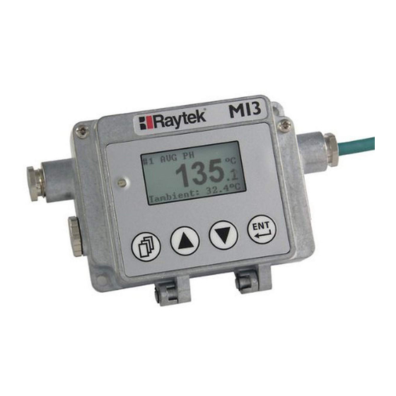
Description 2 Description The MI3 sensor series is the next generation of the well-established “MI class” sensor platform. It will be capable of covering a broad range of applications. The MI3 sensor series introduces various network communications, an externally accessible user interface, improved temperature measurement specifications and capabilities at an economic price. -
Page 12: Overview Comm Boxe
– – Option (…M) Profinet Option (…PN) – – Option (…PN) Ethernet Option (…E) – – Option (…E) Table 1: Capabilities of Communication Boxes 1M, 2M spectral heads require box firmware revision 2.11 or higher info@Raytek-Direct.ca 1.800.868.7495 Rev. F1 05/2013... -
Page 13: Technical Data
30 ms – if more than one sensing head drives an analog output of the communication box at ambient temperature 23°C ±5°C (73°F ±9°F), ε = 1.0, and calibration geometry ambient temperature deviations related to 23°C info@Raytek-Direct.ca 1.800.868.7495 Rev. F1 05/2013... -
Page 14: Comm Box
LTS, G5 8 ms * number of connected heads LTF, 1M, 2M 4 ms * number of connected heads for a zoomed temperature span of < 500°C (932°F) per bus channel per bus channel info@Raytek-Direct.ca 1.800.868.7495 Rev. F1 05/2013... -
Page 15: O Ptical C Harts
Technical Data 3.2 Optical Charts Figure 1: Spot Size Charts info@Raytek-Direct.ca 1.800.868.7495 Rev. F1 05/2013... -
Page 16: E Lectrical S Pecification
Output 1 to 4 0 to 20 mA (active), or 4 to 20 mA (active), or 0 to 5 V, or 0 to 10 V Each output is galvanically isolated from the other and from power supply! info@Raytek-Direct.ca 1.800.868.7495 Rev. F1 05/2013... -
Page 17: E Nvironmental S Pecification
11 to 200 Hz, 3 g above 25 Hz operating, 3 axes / IEC 60068-2-6 Shock 50 g, 11 ms, operating, 3 axes / IEC 60068-2-27 Weight 370 g (13 oz) Material die-cast zinc enclosure info@Raytek-Direct.ca 1.800.868.7495 Rev. F1 05/2013... -
Page 18: Comm Box (Din)
3.5.1 Sensing Head LT, G5 Standard cable length 1 m (3 ft.) Ø 5 mm (0.2 in) Figure 2: Dimensions of LT, G5 Sensing Heads 3.5.2 Sensing Head LTH Figure 3: Dimensions of LTH Sensing Head with separated Electronics info@Raytek-Direct.ca 1.800.868.7495 Rev. F1 05/2013... -
Page 19: Sensing Head 1M, 2M
The box is equipped with three cable feed-through ports – two with IP65 compatible sealing glands, a third sealing gland comes for boxes with fieldbus communications (RS485, Profibus etc.). Boxes without fieldbus have a plugged expansion feed-through port instead (M12x1.5 thread). Figure 5: Dimensions of Communication Box info@Raytek-Direct.ca 1.800.868.7495 Rev. F1 05/2013... -
Page 20: Comm Box (Din)
3.6 Scope of Delivery 3.6.1 Sensing Head Sensing head with 1 m (3 ft.) cable • Laser (1M, 2M heads only) • Mounting nut • 3.6.2 Comm Box Communication box • Software DVD • Quickstart guide • info@Raytek-Direct.ca 1.800.868.7495 Rev. F1 05/2013... -
Page 21: Basics
• Use shielded wire for all input and output connections. • To avoid current equalizations, make sure that a sufficient potential equalization is realized between the sensing head and metal housing of the communication box. info@Raytek-Direct.ca 1.800.868.7495 Rev. F1 05/2013... - Page 22 To avoid ground loops, make sure that only one point is earth grounded, either via the • sensing head, the Comm Box, or power. Please note that: The metal housings of the sensing head and the MI3 communication box are electrically • connected to the shield of the head cable. •...
-
Page 23: Installation
The sensing head provides all IR measurement functionality. The communications box provides an externally accessibly user interface and display, advanced signal processing capability, field wiring terminations and fieldbus functionality with optional RS485 communication interface. info@Raytek-Direct.ca 1.800.868.7495 Rev. F1 05/2013... -
Page 24: Comm Box (Din)
15 mm (0.6 in.) for the high ambient temperature heads (Teflon cable) respectively! The total sensing head cable length for all networked sensing heads must not exceed 30 m (98 ft) for MI3 and 2x30 m (2x98 ft) for MI3M! info@Raytek-Direct.ca 1.800.868.7495... -
Page 25: Comm Box (Metal)
You need to connect the power supply and possibly the signal input/output wires. Use only cable with outside diameter from 4 to 6 mm (0.16 to 0.24 in), wire size: 0.14 to 0.75 mm² (AWG 19 to 26). info@Raytek-Direct.ca 1.800.868.7495... -
Page 26: Comm Box (Metal)
The cable must include shielded wires. It should not be used as a strain relief! 5.4.1 Comm Box (metal) Sensing Head Emissivity Control Ambient Compensation Trigger/Hold head head Alarm: T head Power Supply Figure 14: Terminal Wiring for the Comm Box info@Raytek-Direct.ca 1.800.868.7495 Rev. F1 05/2013... -
Page 27: Comm Box (Din 3Te)
Installation 5.4.2 Comm Box (DIN 3TE) Sensing Heads USB Connector, Mini-B Figure 15: Terminal Wiring for the Comm Box DIN 3TE info@Raytek-Direct.ca 1.800.868.7495 Rev. F1 05/2013... -
Page 28: Comm Box (Din 4 Te)
Installation 5.4.3 Comm Box (DIN 4 TE) Sensing Heads Shunt, deactived USB Connector, Mini-B Figure 16: Terminal Wiring for the Comm Box DIN 4 TE info@Raytek-Direct.ca 1.800.868.7495 Rev. F1 05/2013... -
Page 29: Comm Box (Din 6 Te)
Installation 5.4.4 Comm Box (DIN 6 TE) Sensing Heads Wiring Profibus or Modbus USB Connector, Mini-B Figure 17: Terminal Wiring for the Comm Box DIN 6 TE for Profibus and Modbus info@Raytek-Direct.ca 1.800.868.7495 Rev. F1 05/2013... - Page 30 Installation Sensing Heads USB Connector, Mini-B RJ45 connector Profinet or Ethernet Figure 18: Terminal Wiring for the Comm Box DIN 6 TE for Profinet and Modbus info@Raytek-Direct.ca 1.800.868.7495 Rev. F1 05/2013...
- Page 31 Installation Sensing Heads see section Analog Outputs OUT1 - OUT4, page 38. Analog Outputs USB Connector, Mini-B Figure 19: Terminal Wiring for the Comm Box DIN 6 TE, analog info@Raytek-Direct.ca 1.800.868.7495 Rev. F1 05/2013...
-
Page 32: Emi Resistance For Comm Box (Din)
<Shield>! self-adhesive shield tape to wrap round the cable Shield wire connected to Ferrite Core placed on all wires terminal pin <Shield> except the shield wire Figure 20: Mounting of Shield Wire and Ferrite Core info@Raytek-Direct.ca 1.800.868.7495 Rev. F1 05/2013... -
Page 33: Power On Procedure
Follow the instructions 1 to 4 to add the next head. With each new head detected, the box increases the head address by 1. The head address may be changed later by the user under the dedicated head page. See section 8.2 <Head> Page, page 47. info@Raytek-Direct.ca 1.800.868.7495 Rev. F1 05/2013... - Page 34 USB cable. USB connector, type Mini-B The computer’s USB port Figure 21: USB Connection via the Comm Box (metal) The computer’s USB port Figure 22: USB Connection via the Comm Box (DIN Rail) info@Raytek-Direct.ca 1.800.868.7495 Rev. F1 05/2013...
- Page 35 Operating System <Start> <Settings> <Control Panel> <System> <Hardware> <Device Manager> <Ports (COM & LPT)>. Go there also to get the virtual COM port number for communicating with the DTMD Software. Driver correctly installed! COM port number for DTMD Software! info@Raytek-Direct.ca 1.800.868.7495 Rev. F1 05/2013...
-
Page 36: F Ieldbus
It is strongly recommended to use shielded and pair twisted cables (e.g. CAT.5)! Make sure the network line is terminated! Termination <on> Last Master Slave 1 Slave 2 Slave Figure 23: Network in Linear Topology (daisy chain) info@Raytek-Direct.ca 1.800.868.7495 Rev. F1 05/2013... -
Page 37: Outputs
The signal output can be configured as either current or voltage output. The minimum load impedance for the voltage output must be 10 kΩ. The maximum current loop impedance for the mA output is 500 Ω. The output is short circuit resistant. info@Raytek-Direct.ca 1.800.868.7495 Rev. F1 05/2013... -
Page 38: A Nalog O Utputs Out1 - Out4
RELAY ≤ 48 V RELAY Figure 24: Spike Voltage Limitation for the Alarm Relay info@Raytek-Direct.ca 1.800.868.7495 Rev. F1 05/2013... -
Page 39: T Hermocouple O Utput Tc
This output can be configured as thermocouple output type J, K, R, or S. For that output, you must install a dedicated compensation cable. The output impedance is 20 Ω. The output is short circuit resistant. The outputs <OUT1> and <TC> are not available at the same time! info@Raytek-Direct.ca 1.800.868.7495 Rev. F1 05/2013... -
Page 40: Inputs
Table 3: Ratio between Analog Input Voltage and Emissivity Example: This process requires setting the emissivity: • for product 1: 0.90 • for product 2: 0.40 Following the example below, the operator needs only to switch to position “product 1” or “product 2”. info@Raytek-Direct.ca 1.800.868.7495 Rev. F1 05/2013... -
Page 41: E Missivity ( Digital )
Figure 26: Digital Selection of Emissivity with FTC Inputs The values in the table cannot be changed through the control panel. 7.3 Ambient Temperature Compensation Function: Ambient Temperature Compensation Signal: 0 to 5 V Terminal: FTC2, GND info@Raytek-Direct.ca 1.800.868.7495 Rev. F1 05/2013... - Page 42 Furnace wall 0 – 5 VDC analog output at FTC2 input Sensor 1 targeted to object Thermal radiation of ambient Thermal radiation of target Target object Figure 27: Principle of Ambient Background Temperature Compensation info@Raytek-Direct.ca 1.800.868.7495 Rev. F1 05/2013...
-
Page 43: Trigger/Hold
This temperature will be written to the output until a new transition from high to low occurs at the input FTC3. info@Raytek-Direct.ca 1.800.868.7495 Rev. F1 05/2013... -
Page 44: L Aser S Witching
A transition at the input from logical high level toward logical low level will switch the laser. All sensing heads are effected by the FTC3 input at the same time. Figure 31: Wiring of FTC3 as Laser Switching info@Raytek-Direct.ca 1.800.868.7495 Rev. F1 05/2013... -
Page 45: Operation
Up Button Page Button LCD Display Alarm Indicator Down Button Enter Button Figure 33: Control Panel for the Comm Box (DIN) Signal Processing Head number Object Temperature Parameters Figure 34: Elements of the LCD Display info@Raytek-Direct.ca 1.800.868.7495 Rev. F1 05/2013... - Page 46 Pushing the keys of the control panel will cause the following actions: enters the menu or save parameters enters the next page No action for 10 s forces the unit to leave the menu without saving of parameters. info@Raytek-Direct.ca 1.800.868.7495 Rev. F1 05/2013...
-
Page 47: Head> Page
19.2 Typical Emissivity Values, page 115. <Transmiss.> changes the transmission value when using protective windows. For example, if a protective window is used with the sensor, set the transmission to the appropriate value. info@Raytek-Direct.ca 1.800.868.7495 Rev. F1 05/2013... - Page 48 <Relay Mode> defines the switching behavior for the box internal alarm relay: <normally open>: open contact in non-alarm status <normally closed>: closed contact in non-alarm status <permanently OFF>: permanently open contacts <permanently ON>: permanently closed contacts info@Raytek-Direct.ca 1.800.868.7495 Rev. F1 05/2013...
- Page 49 <Port>: communication port, only changeable at DHCP = off, read-onlyfor Profinet communications <MAC>: MAC address, read-only <Factory default> sets the box back to factory default. The factory default values are to be found in section 18.9 Command Set, page 108. info@Raytek-Direct.ca 1.800.868.7495 Rev. F1 05/2013...
-
Page 50: Box Info> Page
Temp object temperature temperature jump 90% of temperature jump average time Time Figure 35: Averaging A low level input (GND) at external input FTC3 will promptly interrupt the averaging and will start the calculation again. info@Raytek-Direct.ca 1.800.868.7495 Rev. F1 05/2013... -
Page 51: Peak Hold
Once the hold time is exceeded, the valley hold function will reset and the output will resume tracking the object temperature until a new valley is reached. The range for the hold time is 0.1 to 998.9 s info@Raytek-Direct.ca 1.800.868.7495 Rev. F1 05/2013... -
Page 52: Advanced Peak Hold
This magnitude is called hysteresis. output temperature object temperature Temp hysteresis threshold Time Figure 38: Advanced Peak Hold The advanced peak hold function is only adjustable by means of the DataTemp Multidrop Software. info@Raytek-Direct.ca 1.800.868.7495 Rev. F1 05/2013... -
Page 53: Advanced Valley Hold
The advanced peak hold function with averaging is only adjustable by means of the DataTemp Multidrop Software. 8.5.7 Advanced Valley Hold with Averaging This function works similar to the advanced peak hold function with averaging, except it will search the signal for a local minimum. info@Raytek-Direct.ca 1.800.868.7495 Rev. F1 05/2013... -
Page 54: Options
15 m / 49 ft. (…CB15) 30 m / 98 ft. (…CB30) Network communication interfaces: • RS485, Profibus DP, Modbus RTU, Profinet IO, Ethernet All available models are listed under section 2.1 Overview Comm Boxes, page 12. info@Raytek-Direct.ca 1.800.868.7495 Rev. F1 05/2013... -
Page 55: Accessories
5 m (16 ft) cable set to connect to the communication box. Comm Box Head 1 Multi-Channel Box Head 2 (16 ft) Head 8 Figure 40: Multiple Head Configuration with Comm Box Figure 41: Dimensions info@Raytek-Direct.ca 1.800.868.7495 Rev. F1 05/2013... - Page 56 Accessories to Comm Box (MI3COMM or MI3MCOMM) Figure 42: Wiring Diagram for 8 Heads Please note the correct mounting of the cable shield requires a strong metallic contact to the grommet. info@Raytek-Direct.ca 1.800.868.7495 Rev. F1 05/2013...
-
Page 57: Usb/Rs485 Adapter
Figure 43: Correct Mounting of the Cable Shield The total sensing head cable length for all networked sensing heads must not exceed 30 m/98 ft (for MI3) and 2x30 m/2x98 ft (for MI3M)! 10.1.2 USB/RS485 Adapter The USB/RS485 adapter is self-powering via the USB connection. -
Page 58: A Ccessories (Lt, G5 H Eads )
Air Cooling System with 0.8 m (2.6 ft.) air hose (XXXMIACCJ) or with 2.8 m (9.2 ft.) air hose • (XXXMIACCJ1) Right Angle Mirror (XXXMIACRAJ, XXXMIACRAJ1) • Protective Windows • Close Focus Lens (XXXMI3ACCFL) • info@Raytek-Direct.ca 1.800.868.7495 Rev. F1 05/2013... - Page 59 Accessories Adjustable Bracket Communication Box Sensing Head Fixed Bracket Figure 46: Standard Accessories for LT, G5 Heads info@Raytek-Direct.ca 1.800.868.7495 Rev. F1 05/2013...
-
Page 60: Adjustable Mounting Bracket
Accessories 10.2.1 Adjustable Mounting Bracket Figure 47: Adjustable Mounting Bracket (XXXMIACAB) info@Raytek-Direct.ca 1.800.868.7495 Rev. F1 05/2013... -
Page 61: Fixed Mounting Bracket
180°C (356°F) and has limited use for cooling purposes. The recommended air flow rate is 30 to 60 l / min (0.5 to 1 cfm). The max. pressure is 5 bar (73 PSI). info@Raytek-Direct.ca 1.800.868.7495 Rev. F1 05/2013... -
Page 62: Air Cooling System
The air-cooling system comes with a T-adapter including 0.8 m / 31.5 in (optional: 2.8 m / 110 in) air hose and insulation. The T-adapter allows the air-cooling hose to be installed without interrupting the connections to the box. The air-cooling jacket may be combined with the right angle mirror. info@Raytek-Direct.ca 1.800.868.7495 Rev. F1 05/2013... - Page 63 Figure 51: Air Cooling System (XXXMIACCJ) T-Adapter Hose to sensing head Cable to box Fitting free for air connection Hose: inner Ø: 9 mm (0.35 in) outer Ø: 12 mm (0.47 in) Figure 52: Connecting the T-Adapter info@Raytek-Direct.ca 1.800.868.7495 Rev. F1 05/2013...
- Page 64 Hose Length Figure 53: Maximum Ambient Temperature is dependent on Air Flow and Hose Length Note: “Hose Length“ is the length of the hose exposed to high ambient temperature (not the overall length of the hose). info@Raytek-Direct.ca 1.800.868.7495 Rev. F1 05/2013...
- Page 65 ⑤ mounting nut ⑥ preinstalled cable between sensor and box, leading through the T-adapter ⑦ hose connecting nut ⑧ inner hose ⑨ outer hose ⑩ T-adapter ⑪ rubber washer ⑫ plastic compression fitting ⑬ info@Raytek-Direct.ca 1.800.868.7495 Rev. F1 05/2013...
-
Page 66: Right Angle Mirror
For mounting the right angle mirror (XXXMIACRAJ), see section 10.2.3 Air Purge Jacket, page 61. However, instead of using the front part of the air purge jacket ③, mount the right angle mirror. Figure 57: Right Angle Mirror (* with Air Purge) info@Raytek-Direct.ca 1.800.868.7495 Rev. F1 05/2013... -
Page 67: Protective Windows
It withstands ambient temperatures up to 180°C (356°F). For correct temperature readings, the transmission of the close focus lens must be set via the control panel in the communication box. See section 8.2 <Head> Page, page 47! info@Raytek-Direct.ca 1.800.868.7495 Rev. F1 05/2013... -
Page 68: A Ccessories (1M, 2M H Eads )
Figure 60: Spot Size Charts for Close Focus Lens 10.3 Accessories (1M, 2M Heads) Fixed Mounting Bracket (XXXMI3100FB) • Adjustable Mounting Bracket (XXXMI3100ADJB) • Air Purge Collar (XXXMI3100AP) • Right Angle Mirror (XXXMI3100RAM) • Protective Window (XXXMI3100PW) • info@Raytek-Direct.ca 1.800.868.7495 Rev. F1 05/2013... - Page 69 Accessories Adjustable Mounting Bracket Air Purge Collar Fixed Mounting Bracket Protective Window Right Angle Mirror Figure 61: Overview of available accessories info@Raytek-Direct.ca 1.800.868.7495 Rev. F1 05/2013...
-
Page 70: Fixed Mounting Bracket
Accessories 10.3.1 Fixed Mounting Bracket Figure 62: Dimensions of Fixed Mounting Bracket (XXXMI3100FB) info@Raytek-Direct.ca 1.800.868.7495 Rev. F1 05/2013... -
Page 71: Adjustable Mounting Bracket
Air flows into the fitting and out the front aperture. The pressure of air should be 0.6 to 1 bar (8.7 to 15 PSI). Clean, oil free air is recommended. Figure 64: Dimensions of Air Purge Collar (XXXMI3100AP) info@Raytek-Direct.ca 1.800.868.7495 Rev. F1 05/2013... -
Page 72: Right Angle Mirror
(for 1M, 2M models) (248°F) Table 6: Available Protective Windows For correct temperature readings, the transmission of the protective window must be set via the control panel in the communication box. See section 8.2 <Head> Page, page 47! info@Raytek-Direct.ca 1.800.868.7495 Rev. F1 05/2013... - Page 73 Accessories Figure 66: Protective Window info@Raytek-Direct.ca 1.800.868.7495 Rev. F1 05/2013...
-
Page 74: Maintenance
21 to 24 mA 21 to 24 mA Communication error between head and box 10 V 21 to 24 mA 21 to 24 mA * related to zoomed temperature range Table 8: Error Codes for Analog Output info@Raytek-Direct.ca 1.800.868.7495 Rev. F1 05/2013... -
Page 75: C Leaning The L Ens
Do not wipe the surface dry, this may scratch the surface. If silicones (used in hand creams) get on the window, gently wipe the surface with Hexane. Allow to air dry. info@Raytek-Direct.ca 1.800.868.7495 Rev. F1 05/2013... -
Page 76: S Ensing H Ead E Xchange
(head address reserved for that individual head, alarm condition is kept) – the same head connected later will be detected as a known head by keeping the previous address. info@Raytek-Direct.ca 1.800.868.7495 Rev. F1 05/2013... -
Page 77: Datatemp Multidrop Software
• The sensor requires the selection of <ASCII protocol>! • The DTMD software communicates to Comm Boxes only! A multidrop installation is related to a network with multiple Comm Boxes and not to a multiple head system with one Comm box only! info@Raytek-Direct.ca 1.800.868.7495 Rev. F1 05/2013... -
Page 78: Rs485
0 for stand-alone unit or broadcast transmission 13.1 Wiring 13.1.1 Comm Box (metal) Termination Terminal RS485 positive signal (or RxA, or D+) negative signal (or RxB, or D-) Figure 67: RS485 Terminal for Comm Box (metal) info@Raytek-Direct.ca 1.800.868.7495 Rev. F1 05/2013... -
Page 79: Comm Box (Din)
(negative signal) (positive signal) Shield n.a. n.a. , yellow n.a. , red n.a. Figure 68: Terminal for Comm Box (DIN 6TE) 13.2 ASCII Programming For the programming details, see section 18 ASCII Programming, page 103. info@Raytek-Direct.ca 1.800.868.7495 Rev. F1 05/2013... -
Page 80: Profibus
Profibus 14 Profibus Profibus DP-V0 defines a cyclical data exchange between a master (e.g. a PLC) and a slave (MI3 sensor). At start-up first an array of parameters (Profibus specific data) is sent from the master to the slave, followed by an array with the configuration (sensor specific presetting’s taken from the GSD file) also sent from the master to the slave. - Page 81 Figure 71: Profibus Pin Assignment for Sub-D / M12 Connector The termination for Profibus networks must be realized externally by the user! Slave Slave Slave Termination Slave Slave Figure 72: Exemplary Network with External Termination info@Raytek-Direct.ca 1.800.868.7495 Rev. F1 05/2013...
-
Page 82: Comm Box (Din)
(positive signal) (not supported while termination “on”) (negative signal) (positive signal) Shield n.a. , yellow Blinking: 0.5 Hz: parameters / 1 Hz: configuration , red ON: data-exchange Figure 73: Terminal for Comm Box (DIN 6TE) info@Raytek-Direct.ca 1.800.868.7495 Rev. F1 05/2013... -
Page 83: P Rogramming
°C /°F dev. range min.. 56, 57 Setpoint relay Head_1 in °C /°F dev. range min.. Relay alarm output control Head_1 0 = off 0, 1 or 2 1 = target temp. 2 = internal temp. info@Raytek-Direct.ca 1.800.868.7495 Rev. F1 05/2013... -
Page 84: Input Data
If all heads (maximal eight) are connected and configured then 35 bytes are transferred. If only one head is connected but eight heads are configured then also 35 bytes are transferred. info@Raytek-Direct.ca 1.800.868.7495 Rev. F1 05/2013... -
Page 85: Output Data
The device uses the first 32 bytes of the Identifier Related Diagnosis. The first 6 bytes consist of Standard Diagnosis dedicated to bus parameters. In this field byte 4 and 5 give the unit identifier (0D36 in our case). info@Raytek-Direct.ca 1.800.868.7495 Rev. F1 05/2013... - Page 86 up to which index the user data is valid 11 (0x0B) box error code 12 … 22 (0x0C …16) last MI3-command which created an error as answer; ASCII code 23 (0x17) head_1 error code 24 (0x18)
- Page 87 Profibus Highest Last bad head Head 1 Head 8 error bits error bits Figure 75: Diagnose Data with Error “Cable Break at Head 1” info@Raytek-Direct.ca 1.800.868.7495 Rev. F1 05/2013...
-
Page 88: Modbus
+ 5 V (output, used for external termination) , yellow ON while communicating , red Error Figure 76: Modbus Terminal for Comm Box (metal) The termination for Modbus networks must be realized externally by the user! info@Raytek-Direct.ca 1.800.868.7495 Rev. F1 05/2013... -
Page 89: Comm Box (Din)
(not supported while termination “on”) D1_2 (positive signal) (not supported while termination “on”) D0_1 (negative signal) D1_1 (positive signal) Shield (output) n.a. , yellow Communication , red Error Figure 77: Terminal for Comm Box (DIN 6TE) info@Raytek-Direct.ca 1.800.868.7495 Rev. F1 05/2013... -
Page 90: P Rogramming
Comm Box. Items (registers, discretes or coils) are addressed starting at zero. Therefore items numbered 1-10000 are addressed as 0-9999. Start Size Modbus Access Data Content Values MI3[M] address [bits] Type command input register short error code for last... - Page 91 Modbus Start Size Modbus Access Data Content Values MI3[M] address [bits] Type command discretes input bit field Get connected heads bit 0: head 1 .. bit 7: head 8 bit high: head connected bit low: head disconnected discretes input bit field Get registered heads bit 0: head 1 ..
-
Page 92: Head Parameter
Modbus 15.2.2.2 Head Parameter <n> … head number, depending on the registered heads Starting Size Modbus Data Content Values MI3[M] address [bits] Access Type command <n>005 discretes bit field Head Status bit0: Temperature Unit input (0: deg. C, 1: deg. F) - Page 93 Modbus Starting Size Modbus Data Content Values MI3[M] address [bits] Access Type command <n>220 holding char Emissivity Source I: internal command register E: ext. input (0V .. 5V) D: digital selected FTC1-3 <n>230 holding float Presel. Emissivity 0.1 .. 1.1 register <n>240...
-
Page 94: Ethernet
8 sensing heads Connection: M12 or RJ45 electrically isolated An opened Ethernet port will be closed automatically by the MI3 communication box if there is no data traffic within 120 s! 16.1 Wiring 16.1.1 Comm Box (metal) The connector on the box side is an M12 plug-in connector, 4 pin D-coded, suited for industrial Ethernet with IP67 protection rate with a screw retention feature. -
Page 95: Http S Erver
Ethernet 16.3 http Server The MI3 Comm Box with Ethernet provides a built-in http server for one or more client computers based on the http protocol within an Intranet. For getting/setting the network address through the control panel of the Comm Box, see section 8.3 <Box Setup>... -
Page 96: Data Logging
Ethernet 16.3.1 Data Logging With the data logging function on the MI3 communication box you can record the temperature values over time directly in the internal memory of the box. Pressing on the <Start> button triggers the data storage in accordance to the defined time interval, given in seconds. -
Page 97: Profinet
Profinet 17 Profinet The Profinet fieldbus MI3 communication box (called fieldbus communicator) maps the object and internal temperature of all pyrometer modules on Profinet IO. In the initialization phase, the fieldbus communicator determines the physical structure of the node and creates a local process image with all pyrometers. -
Page 98: P Rogramming
Pyrometer modules is based on the device’s GSD file. 17.2.1.1 GSD File Under Profinet IO, the features of the devices are described by the manufacturer in form of a GSD file and made available to the user. The GSD file for the MI3 IO device: GSDML-V2.25-Raytek-MI3-20130221 17.2.1.2 Configuration The I/O device is configured in accordance with the physical arrangement of the node (slot oriented). -
Page 99: Station Parameters
Source (head) for output 2 Set head number 1..8 Source (type) for output 2 Set type of source for output 2 Internal temperature Object temperature Analog output 2 mode Set output mode 0…20mA 4…20mA 0…5V 0…10V tristate (disabled) info@Raytek-Direct.ca 1.800.868.7495 Rev. F1 05/2013... -
Page 100: Pyrometer Module Parameters
Profinet I/O controller message active Message return of module The return of pyrometer is not transferred to the message inactive Profinet I/O controller is transferred to the Profinet I/O controller message active info@Raytek-Direct.ca 1.800.868.7495 Rev. F1 05/2013... -
Page 101: Input Data Structure
In productive data exchange between the I/O controller and the fieldbus communicator, one byte IOPS process data qualifiers are available for each module providing information of the validity of the pyrometer module data (good/ bad). In the event of an error occurs during operation, the problem- info@Raytek-Direct.ca 1.800.868.7495 Rev. F1 05/2013... -
Page 102: Error Bits Of The Station Diagnosis (Optional)
17.2.5.2 Error Bits of the Pyrometer Module Diagnosis (optional) Bit Description Object temperature out of range Ambient (internal) temperature out of range Parameter error Register write error Self test error reserved head registered but not connected cable break? info@Raytek-Direct.ca 1.800.868.7495 Rev. F1 05/2013... -
Page 103: Ascii Programming
“?“ is the command for “Request“ “E“ is the parameter requested <CR> (carriage return, 0Dh) is closing the request. Remark: It is possible to close with <CR> <LF>, 0Dh, 0Ah, but not necessary. Setting a parameter (Poll Mode) info@Raytek-Direct.ca 1.800.868.7495 Rev. F1 05/2013... -
Page 104: D Evice I Nformation
For the calculation of the temperature value, it is possible to set an offset (relative number to be added to the temperature value), and a gain value. DG=1.0000 Gain adjustment for the temperature signal DO=0 Offset adjustment for the temperature signal info@Raytek-Direct.ca 1.800.868.7495 Rev. F1 05/2013... -
Page 105: Temperature Pre-Processing
To activate these emissivity settings, you need to have the 3 external inputs (FTC) connected. According to the digital combination on the FTC wires, one of the table entries will be activated, see section 7.2 Emissivity (digital), page 41. info@Raytek-Direct.ca 1.800.868.7495 Rev. F1 05/2013... -
Page 106: Post Processing
2 is set to 500°C L2O=0 the minimum current/voltage value for output 2 is set to 0°C Remark: You cannot set this value for thermocouple output. The minimum span between the maximum / minimum settings is 20 K. info@Raytek-Direct.ca 1.800.868.7495 Rev. F1 05/2013... -
Page 107: Alarm Output
The communication boxes support up to 8 heads. To direct a command to one head among the 8 possible, it is necessary to “address” the head command. Therefore, a number between 1 and 8 is set prior to the head command. info@Raytek-Direct.ca 1.800.868.7495 Rev. F1 05/2013... -
Page 108: A Ddressing Of M Ultiple B Oxes (Rs485)
Advanced hold with 0 – 999.9 s 000.0s √ √ √ average float Control ambient 0 – sensor temp. √ √ √ background temp. 1 – via number compensation 2 – via ext. input info@Raytek-Direct.ca 1.800.868.7495 Rev. F1 05/2013... - Page 109 (analog outputs) Box Status Codes (read only): Self-test error BIT0 Box ambient temperature out of range BIT1 Sensing head communication error BIT2 Parameter error BIT3 Register write error BIT4 Analog module error BIT5 Profinet ready BIT6 info@Raytek-Direct.ca 1.800.868.7495 Rev. F1 05/2013...
- Page 110 BIT3 // 1 = error Register write error BIT4 // 1 = error Self-test error BIT5 // 1 = error {reserved} BIT6 Ambient temperature compensation BIT7 // 0 = off, 1 = on for MI3100 heads only info@Raytek-Direct.ca 1.800.868.7495 Rev. F1 05/2013...
- Page 111 √ √ control integer 1 = on 2 = Target norm. open depreciated for MI3 (use 3 = Target norm. closed the commands KB and 4 = Intern norm. open KH instead of) 5 = Intern norm. closed Relay alarm output 0 = off √...
- Page 112 !XUMI3COMM set at production √ Serial number e.g. !XV98123 set at production B √ Advanced hold nnnn √ √ hysterese Mode 0 and 4 for MI3MCOMMA only Mode 5 to 8 for MI3COMM only info@Raytek-Direct.ca 1.800.868.7495 Rev. F1 05/2013...
- Page 113 ASCII Programming info@Raytek-Direct.ca 1.800.868.7495 Rev. F1 05/2013...
-
Page 114: Ascii Commands For Ethernet And Profinet
Data logging interval 1 – 2097120 s 2.19 √ (Ethernet only) Ethernet String, 4 char 1.00 2.19 √ Version Handle Profinet Name String, 10 char commbox 2.19 √ Reset Ethernet module 2.19 √ Table 16: Command Set info@Raytek-Direct.ca 1.800.868.7495 Rev. F1 05/2013... -
Page 115: Appendix
For translucent materials such as plastic foils or glass, assure that the background is uniform • and lower in temperature than the object. Mount the instrument perpendicular to the surface, if possible. In all cases, do not exceed • angles more than 30° from incidence. info@Raytek-Direct.ca 1.800.868.7495 Rev. F1 05/2013... - Page 116 0.3-0.7 0.2-0.6 Unoxidized 0.1-0.15 0.1-0.15 Monel (Ni-Cu) 0.1-0.5 0.1-0.5 0.1-0.14 Nickel Oxidized 0.3-0.6 0.3-0.6 0.2-0.5 Electrolytic 0.1-0.15 0.1-0.15 0.05-0.15 Platinum Black Silver 0.02 0.02 0.02 Steel Cold-Rolled 0.8-0.9 0.8-0.9 0.7-0.9 Ground Sheet 0.5-0.7 0.5-0.7 0.4-0.6 info@Raytek-Direct.ca 1.800.868.7495 Rev. F1 05/2013...
- Page 117 Tin (Unoxidized) 0.05 0.05 0.05 Titanium Polished 0.1-0.3 0.1-0.3 0.05-0.2 Oxidized 0.5-0.7 0.5-0.7 0.5-0.6 Tungsten 0.05-0.5 0.05-0.5 0.03 Polished 0.05-0.25 0.05-0.25 0.03-0.1 Zinc Oxidized Polished 0.03 0.03 0.02 Tab. 17: Typical Emissivity Values for Metals info@Raytek-Direct.ca 1.800.868.7495 Rev. F1 05/2013...
- Page 118 Paper (any color) 0.95 0.95 Plastic, greater than 0.95 0.95 500 µm (0.02 in) thickness Rubber 0.95 Sand Snow — Soil — 0.9-0.98 Water — 0.93 Wood, Natural 0.9-0.95 0.9-0.95 Tab. 18: Typical Emissivity Values for Non-Metals info@Raytek-Direct.ca 1.800.868.7495 Rev. F1 05/2013...
- Page 119 Notes 20 Notes info@Raytek-Direct.ca 1.800.868.7495 Rev. F1 05/2013...
Need help?
Do you have a question about the MI3 and is the answer not in the manual?
Questions and answers