
Related Manuals for RayTek TX


Summary of Contents for RayTek TX
-
Page 1: Operating Instructions
Infrared Sensor Operating Instructions Rev. O7 07/2017 50501 info@Raytek-Direct.com 1.888.610.7664... -
Page 2: Compliance Statement
This product meets requirements for industrial (Class A) electromagnetic wave equipment and the seller or user should take notice of it. This equipment is intended for use in business environments and is not to be used in homes. info@Raytek-Direct.com 1.888.610.7664... -
Page 3: Table Of Contents
..............................29 VERVIEW 6.2 A ..........................30 DJUSTABLE RACKET 6.3 A ........................... 30 URGE OLLAR 6.4 R ..........................30 IGHT NGLE IRROR 6.5 S ............................31 IGHTING IEWER 6.6 P ............................31 DAPTER 6.7 A ........................32 DJUSTABLE DAPTER info@Raytek-Direct.com 1.888.610.7664... - Page 4 9 APPENDIX ............................... 42 9.1 D ........................ 42 ETERMINATION OF MISSIVITY 9.2 T ........................42 YPICAL MISSIVITY ALUES 9.3 D ............................. 46 ISPLAY ONITOR 9.3.1 Installation with the Sensor ........................ 46 9.4 ATEX C ......................47 ERTIFICATE OF ONFORMITY NOTES info@Raytek-Direct.com 1.888.610.7664...
-
Page 5: Safety Instructions
All instrument parts supplied with electricity must be covered to prevent physical contact and other hazards at all times. For ATEX certified units comply with the installation and safety instructions for electrical equipment in potentially explosive atmospheres. info@Raytek-Direct.com 1.888.610.7664 Rev. O7 07/2017... -
Page 6: Technical Data
Dimensions / Weight Sensor L: 187 mm; Ø: 42 mm / 330 g (Length 7.36 inches, dia 1.65 inches) with water cooling L: 187 mm; Ø: 60 mm / 595 g (Length 7.36 inches, dia 2.36 inches) info@Raytek-Direct.com 1.888.610.7664 Rev. O7 07/2017... -
Page 7: Optical Diagrams
= greatest known diameter of target spot = distance to unknown target spot = distance to smaller known target spot = distance to greater known target spot Figure 1: How to read the optical diagrams info@Raytek-Direct.com 1.888.610.7664 Rev. O7 07/2017... - Page 8 Distance D Sensor to Object [mm] Distance D Sensor to Object [mm] * Focus Point D:S = 60:1 Far Field D:S = 14:1 * Focus Point D:S = 60:1 Far Field D:S = 7:1 Figure 2: Optical Diagrams info@Raytek-Direct.com 1.888.610.7664 Rev. O7 07/2017...
-
Page 9: Scope Of Delivery
Technical Data 2.3 Scope of Delivery All models are provided with: operator´s manual a fixed bracket mounting nut models have 4 to 20 mA output info@Raytek-Direct.com 1.888.610.7664 Rev. O7 07/2017... -
Page 10: Basics
In ambient conditions up to 315°C (600°F), the ThermoJacket housing should be used. info@Raytek-Direct.com 1.888.610.7664 Rev. O7 07/2017... -
Page 11: Atmospheric Quality
This measuring error when measuring objects with low emissivity can be reduced to a minimum if particular care is taken during installation, and the sensing head is shielded from these reflecting radiation sources. info@Raytek-Direct.com 1.888.610.7664 Rev. O7 07/2017... -
Page 12: Installation
650 m line length: 0.5 mm cross section AWG20 up to 1500 m multiple wire line lengths: 1.5 mm cross section up to 3000 m single wire line lengths: 2.5 mm cross section info@Raytek-Direct.com 1.888.610.7664 Rev. O7 07/2017... -
Page 13: Dimensions Of Sensor
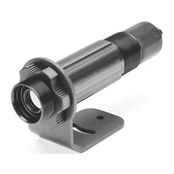
Figure 5: Fixed bracket XXXTXXACFB (left) with sensor delivered 4.3 Connecting the Signal Line Before connecting the cable to the sensor (standard and Smart models) you should unscrew the cap from the back of the sensor. Proceed as follows: info@Raytek-Direct.com 1.888.610.7664 Rev. O7 07/2017... - Page 14 Tighten the PG nut firmly. Screw the end-cap firmly onto the sensor until it is tight (flush with the sensor body). IMPORTANT: Neither the end-cap nor the cable gland should have any play after tightening. info@Raytek-Direct.com 1.888.610.7664 Rev. O7 07/2017...
- Page 15 The outside diameter of the connecting cables (round cable) should lie between 4 to 6 mm (about 0.2 inches). Note that it might be necessary to additionally seal the cable entry to allow IP65 with smaller cables! info@Raytek-Direct.com 1.888.610.7664 Rev. O7 07/2017...
-
Page 16: Basic Model
The superposition of analog and digital signals is described by the HART protocol. Sensors which are programmable in this way are called SMART sensors. Apart from the Smart model, a HART/RS232 info@Raytek-Direct.com 1.888.610.7664 Rev. O7 07/2017... -
Page 17: Hart/Rs232 Adapter
Computer COM-Port Figure 10: Typical installation of Smart model using the external resistor Controller, Display, or just nothing Computer within the current loop. COM-Port Figure 11: Typical installation of Smart model using the internal resistor info@Raytek-Direct.com 1.888.610.7664 Rev. O7 07/2017... -
Page 18: Address Assignment For Multiple Sensors
For configuring the sensor, go to the <Sensor> <Sensor Setup> menu in the software. Sensor Figure 12: Address assignment with external (left) and internal (right) resistor info@Raytek-Direct.com 1.888.610.7664 Rev. O7 07/2017... -
Page 19: Installation Of Multiple Sensors (Digital, Address Mode)
The sensing heads are factory-programmed with ”Polling Address 0”! When installing a number of sensors, note that each sensing head must first be assigned a separate polling address (1 to 15), section 4.5.4 Address Assignment for Multiple Sensors on page 21). info@Raytek-Direct.com 1.888.610.7664 Rev. O7 07/2017... -
Page 20: Installation Of Multiple Sensors (Digital And Analog, Address Mode)
To avoid this, a sensor can be named by means of a so called tag. The tag will be stored within the units memory and can later be used to identify the sensor uniquely. info@Raytek-Direct.com 1.888.610.7664 Rev. O7 07/2017... -
Page 21: Alarm Output
Use the circuit diagram. The LED is operated with 10 mA and could be used as an indicator, or as an optocoupler. The alarm current does not influence the signal current (4 to 20 mA current loop). Figure 17: Using the alarm output info@Raytek-Direct.com 1.888.610.7664 Rev. O7 07/2017... -
Page 22: Options
Chilled water below 10°C (50°F) is not recommended, see section 5.1.2 Avoidance of Condensation page 26. The Air/Water-Cooled Housing is also available in stainless steel (…S). Stainless Steel Fittings Figure 18: Sensor with Air/Water-Cooled Housing info@Raytek-Direct.com 1.888.610.7664 Rev. O7 07/2017... -
Page 23: Connecting
To avoid condensation, the temperature of the cooling media and the flow rate have to ensure a minimum device temperature. The minimum device temperature depends on the ambient temperature and the relative humidity, please consider the following table. info@Raytek-Direct.com 1.888.610.7664 Rev. O7 07/2017... - Page 24 = 50 °C 140°F are not recommended due to Relative humidity = 40 % the temperature limitation of the Minimum device temperature = 30 °C device. The use of lower temperatures is at your own risk! info@Raytek-Direct.com 1.888.610.7664 Rev. O7 07/2017...
-
Page 25: Atex Intrinsic Safety
Earth grounding of the cable shield Installing the unit’s metallic enclosure on an earth grounded mounting bracket or on any other grounded bases Please also consider section 9.4 ATEX Certificate of Conformity, page 47. info@Raytek-Direct.com 1.888.610.7664 Rev. O7 07/2017... -
Page 26: Accessories
(XXXTXXACFB) Sighting Viewer (XXXTXXACSV) Adjustable Bracket (XXXTXXACAB) Right Angle Mirror (XXXTXXACRA) Sensor with Air-/Water Cooled Housing (Option) Air Purge Collar (XXXTXXACAP) Mounting Nut (XXXTXXACMN) ThermoJacket and Accessories (RAYTXXTJ3M) Figure 20: Overview to the available accessories info@Raytek-Direct.com 1.888.610.7664 Rev. O7 07/2017... -
Page 27: Adjustable Bracket
The mirror must be installed after the bracket and after the Air Purge Collar and screwed in fully. In dusty or contaminated environments, air purging is required to keep the mirror surface clean. info@Raytek-Direct.com 1.888.610.7664 Rev. O7 07/2017... -
Page 28: Sighting Viewer
Sighting Viewer Tool. Figure 24: Sighting Viewer 6.6 Pipe Adapter The adjustable pipe adapter (XXXTXXACPA) is available to connect a sighting tube or conduit to a sensor with or without water/air cooled housing. info@Raytek-Direct.com 1.888.610.7664 Rev. O7 07/2017... -
Page 29: Adjustable Pipe Adapter
315°C (600°F). The rugged cast aluminum housing completely encloses the sensor and provides water cooling as well as air purging. Sensing heads can easily be installed or removed with the ThermoJacket housing in its mounted position. info@Raytek-Direct.com 1.888.610.7664 Rev. O7 07/2017... - Page 30 Accessories Figure 27: ThermoJacket (RAYTXXTJ3) For more information see the ThermoJacket’s manual. info@Raytek-Direct.com 1.888.610.7664 Rev. O7 07/2017...
-
Page 31: Industrial Power Supply
AC Input 100 – 240 VAC 44/66 Hz DC Output 24 VDC / 1.3 A Cross sections input/output 0.08 to 2.5 mm² (AWG 28 to 12) Figure 28: Industrial Power Supply (XXXSYSPS) Copyright Wago ® info@Raytek-Direct.com 1.888.610.7664 Rev. O7 07/2017... -
Page 32: Protective Window
If the smart model is used, adjust the transmissivity in the software until the same temperature is displayed, as it was determined without the protective window. For more information regarding the mounting of a protective window, see section 8.4 Replacing a Protective Window on page 40. info@Raytek-Direct.com 1.888.610.7664 Rev. O7 07/2017... -
Page 33: Usb/Rs232 Adapter
151 x 75 x 26 mm (5.9 x 2.9 x 1 in) Figure 29: USB/RS232 Converter (XXXUSB485S) TX Sensor HART/RS232 Adapter RS232/USB Adapter Computer Figure 30: Principal bridging a TX sensor with HART communication via RS232 to USB communications info@Raytek-Direct.com 1.888.610.7664 Rev. O7 07/2017... -
Page 34: Software
If you notice that not all devices were found, click on the <Back> button to return to the previous screen, then go check your sensor connections. After checking, click on the <Continue> button so the software rescans for connected devices. info@Raytek-Direct.com 1.888.610.7664 Rev. O7 07/2017... -
Page 35: Sensor Setup
In the <Sensor Setup> screen, you may configure the settings for the signal processing (emissivity, ambient control, hold modes, fail safe mode), the output signals (alarms and relay), and the advanced setup (polling address, descriptions). Figure 33: <Sensor Setup> Menu See the DataTemp Multidrop software help for further instructions! info@Raytek-Direct.com 1.888.610.7664 Rev. O7 07/2017... -
Page 36: Maintenance
21 mA Target temperature under range 4 mA Target temperature over range 20 mA Never rely exclusively on the automatic error indication when monitoring critical heating processes. It is strongly recommended to take additional safety measures! info@Raytek-Direct.com 1.888.610.7664 Rev. O7 07/2017... -
Page 37: Cleaning The Lens
Now gently unscrew the protective window from its mount by turning to the left. Take care to screw in the new protective window as tight as possible, but do not over tighten! info@Raytek-Direct.com 1.888.610.7664 Rev. O7 07/2017... -
Page 38: Models Produced Before May 1999
Replace the protective window using the plastic levers supplied with the spare window. Place the levers’ blades beneath the projection of the protective window. Now gently lever the protective window from its mount. Figure 35: Replacing the Protective Window info@Raytek-Direct.com 1.888.610.7664 Rev. O7 07/2017... -
Page 39: Appendix
These include the following: Temperature Angle of measurement Geometry (plane, concave, convex) Thickness Surface quality (polished, rough, oxidized, sandblasted) Spectral range of measurement Transmissivity (e.g. thin films plastics) info@Raytek-Direct.com 1.888.610.7664 Rev. O7 07/2017... - Page 40 0.1-0.3 0.05-0.25 0.05-0.2 Rusted 0.6-0.9 0.5-0.8 0.5-0.7 Molten 0.35 0.4-0.6 — — Iron, Cast Oxidized 0.7-0.95 0.65-0.95 0.6-0.95 Unoxidized 0.35 0.25 Molten 0.35 0.3-0.4 0.2-0.3 0.2-0.3 Iron, Wrought Dull 0.95 Tab. 4: Typical Emissivity Values info@Raytek-Direct.com 1.888.610.7664 Rev. O7 07/2017...
- Page 41 Tin (Unoxidized) 0.25 0.1-0.3 0.05 0.05 Titanium Polished 0.5-0.75 0.2-0.5 0.1-0.3 0.05-0.2 Oxidized 0.6-0.8 0.5-0.7 0.5-0.6 Tungsten 0.1-0.6 0.05-0.5 0.03 Polished 0.1-0.3 0.05-0.25 0.03-0.1 Zinc Oxidized 0.15 Polished 0.05 0.03 0.02 Tab. 5: Typical Emissivity Values info@Raytek-Direct.com 1.888.610.7664 Rev. O7 07/2017...
- Page 42 0.95 Plastic (opaque, over 20 mils) — 0.95 0.95 Rubber — 0.95 Sand — Snow — — Soil — — 0.9-0.98 Water — — 0.93 Wood, Natural — 0.9-0.95 0.9-0.95 Tab. 6: Typical Emissivity Values info@Raytek-Direct.com 1.888.610.7664 Rev. O7 07/2017...
-
Page 43: Display Monitor
A possible installation is given in the figure below. For other installations see the figures in section 4.5 Smart Model on page 19. Computer COM-Port Sensor Monitor Figure 38: Sensor in digital communication, display and power with the monitor info@Raytek-Direct.com 1.888.610.7664 Rev. O7 07/2017...
Need help?
Do you have a question about the TX and is the answer not in the manual?
Questions and answers