Table of Contents
Advertisement
Advertisement
Table of Contents

Related Manuals for RayTek TX


Summary of Contents for RayTek TX
-
Page 1: Operating Instructions
Infrared Sensor Operating Instructions Rev. O 06/2011 50501... - Page 3 Thank you for purchasing this Raytek product. Register today at www.raytek.com/register to receive the latest updates, enhancements and software upgrades! © Raytek Corporation. Raytek and the Raytek Logo are registered trademarks of Raytek Corporation. All rights reserved. Specifications subject to change without notice.
- Page 4 ARRANTY The manufacturer warrants this product to be free from defects in material and workmanship under normal use and service for a period of two years from date of purchase except as hereinafter provided. This warranty extends only to the original purchaser. This warranty shall not apply to fuses or batteries. Factory calibration is warranted for a period of one year.
-
Page 5: Table Of Contents
Content 1 SAFETY INSTRUCTIONS ..........................7 2 TECHNICAL DATA ............................8 2.1 M ......................... 8 ODELS AND ARAMETERS 2.2 O ............................. 9 PTICAL IAGRAMS 2.3 S ............................ 11 COPE OF ELIVERY 3 BASICS ................................12 3.1 M ................... 12 EASUREMENT OF NFRARED EMPERATURE 3.2 D... - Page 6 7.1 R ............................32 EQUIREMENTS 7.2 I ........................32 NSTALLATION AND TART 7.3 S ............................33 ENSOR ETUP 8 MAINTENANCE ............................34 8.1 T ....................34 ROUBLESHOOTING INOR ROBLEMS 8.2 A ......................34 UTOMATIC RROR NDICATION 8.3 C ..........................35 LEANING THE 8.4 R ......................
-
Page 7: Safety Instructions
Safety Instructions This document contains important information, which should be kept at all times with the instrument during its operational life. Other users of this instrument should be given these instructions with the instrument. Eventual updates to this information must be added to the original document. The instrument can only be operated by trained personnel in accordance with these instructions and local safety regulations. -
Page 8: Technical Data
Technical Data 2.1 Models and Parameters In general, there are two models available. The basic model (TXC, for °C, and TXF, for °F) and the Smart model (TXS). The model descriptor is followed by the description for the optical characteristic, see following page): Optical characteristic LTPSF LTSF... -
Page 9: Optical Diagrams
Technical Data 2.2 Optical Diagrams The optical diagrams indicate the target spot diameter at any given distance between the target object and the sensing head. All target spot sizes indicated in the optical diagrams are based on 90% energy. Distance D (in) Target Spot Diameter S (in) Distance between Sensor and Object [in] Target Spot Diameter... - Page 10 Technical Data Plastic Lens, Standard Focus SF Plastic Lens, Close Focus CF Distance D Sensor to Object [in] Distance D Sensor to Object [in] LTPSF LTPCF1 Distance D Sensor to Object [mm] Distance D Sensor to Object [mm] * Focus Point D:S = 15:1 Far Field D:S = 14:1 * Focus Point D:S = 7:1 Far Field D:S = 4:1 Low and Medium Temperature Ranges, Low and Medium Temperature Ranges,...
-
Page 11: Scope Of Delivery
Technical Data 2.3 Scope of Delivery All models are provided with: operator´s manual a fixed bracket mounting nut models have 4 to 20 mA output Rev. O 06/2011... -
Page 12: Basics
Basics 3.1 Measurement of Infrared Temperature Everything emits an amount of infrared radiation according to its surface temperature. The intensity of the infrared radiation changes according to the temperature of the object. Depending on the material and surface properties, the emitted radiation lies in a wavelength spectrum of approximately 1 to 20 µm. -
Page 13: Atmospheric Quality
Basics 3.4 Atmospheric Quality In order to prevent damage to the lens and erroneous readings, the lens should always be protected from dust, smoke, fumes, and other contaminants. For this purpose an air purge collar is available. You should only use oil free, clean “instrument“ air. 3.5 Electrical Interference To minimize electrical or electromagnetic interference, follow these precautions: Mount the sensor as far away as possible from possible sources of interference such as... -
Page 14: Installation
Installation The infrared sensor provides a standard two-wire current loop output and has been designed for use in harsh industrial environments. The Smart model allows the remote programming of the temperature range, alarm values and other functions. 4.1 Wire Parameters for Current Loop You should use shielded twisted pairs or multiple twisted pairs with a joint shield. -
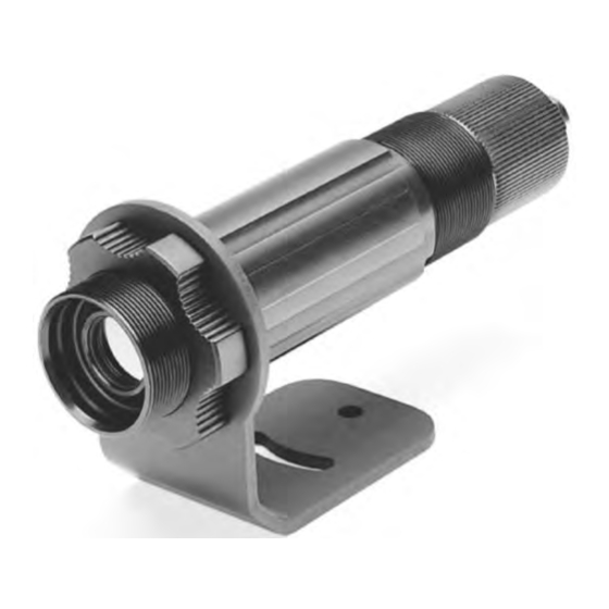
Page 15: Dimensions Of Sensor
Installation 4.2 Dimensions of Sensor All sensors are supplied with a fixed bracket and mounting nut. Alternatively, the sensor may also be mounted using customer-supplied accessories. A pipe adapter and other accessories may also be used (see section 6.1 Overview on page 26). - Page 16 Installation Prepare the cable, remove about 6cm (2.36 in) of the Unscrew the end-cap until it can be pulled away insulation. Shorten the shield to about 1cm (0.4 in). Tin- from the sensor body. coat the connecting leads. Open the PG threaded cable gland. The cable gland consists of a PG nut, a plastics part and a metal cone ring.
-
Page 17: Basic Model
Installation 4.4 Basic Model The standard model is available for °C or °F. It provides a 2 pin screw-jumper terminal for connecting the 4 to 20 mA current loop. The polarity is indicated on the panel. Above the screw-jumper terminal there are two rotary switches for emissivity setting. -
Page 18: Hart/Rs232 Adapter
Installation which are programmable in this way are called SMART sensors. Apart from the Smart model, a HART/RS232 adapter is also available. This adapter allows programming of infrared sensing heads using a computer with an RS232 interface. 4.5.2 HART/RS232 Adapter The adapter (XXXTXACRCK) allows both remote setting and signal processing of one or more sensors in a 4 to 20 mA current loop. -
Page 19: Address Assignment For Multiple Sensors
Installation 4.5.4 Address Assignment for Multiple Sensors The sensing heads are factory-programmed with ”Polling Address 0”! When installing a number of sensors, note that each sensing head must first be assigned a separate polling (1 to 15). To do this, use the software supplied with the Smart model, and the HART/RS232 adapter: Install the software, see software manual. -
Page 20: Installation Of Multiple Sensors (Digital, Address Mode)
Installation 4.5.5 Installation of Multiple Sensors (digital, address mode) Maximum 15 sensors can be used. The polling address must always be >0. Communication is purely digital, no analog current output is provided Set each sensor failsafe mode to “minimum” OWER UPPLY HART/RS232 Shield (6) -
Page 21: Installation Of Multiple Sensors (Digital And Analog, Address Mode)
Installation 4.5.6 Installation of Multiple Sensors (digital and analog, address mode) Maximum 12 sensors can be used. Analog and digital communication for the sensor with polling address 0. Communication for the remaining 11 sensors purely digital. HART/RS232 Shield (6) OWER UPPLY Adapter Sensors Voltage [V] Op. -
Page 22: Alarm Output
Installation Shield (6) HART/RS232 Adapter Monitor Figure 16: All sensors in digital communication and with analog current output In case of having more than 3 units, please contact your local dealer for additional information for installing! To prepare sensors for tag mode: The sensing heads are factory-programmed with ”Polling Address 0”. -
Page 23: Options
Options A full range of options for various applications and environments are available. Options are factory- installed and must be specified at the time of placing the order: °C or °F (basic model only) Air/Water cooled housing (Option: …W), includes air purge Intrinsically-safe rating for smart models, EX II2G EEx ib IIC T4 (…IS2) Manufacturer's calibration certificate based on NIST/DKD probes (XXXTXCERT) Sensor in stainless steel (…S) -
Page 24: Connecting
Options 5.1.1 Connecting : This information is especially important to European customers concerning UROPEAN USTOMERS the use of NPT and metric threads. As a standard the accessory parts are supplied with stainless steel fittings and non-metric 1/8” NPT threads. If you intend to supply the cooling media through pipes or hoses, we recommend using the following additional accessories. -
Page 25: Avoidance Of Condensation
Options 5.1.2 Avoidance of Condensation If environmental condition makes water cooling necessary, it is strictly recommended to check whether condensation will be a real problem or not. Water cooling also causes a cooling of the air in the inner part of the device. Thereby the capability of the air to store water decreases. -
Page 26: Accessories
Accessories 6.1 Overview For all models: Mounting Nut XXXTXXACMN Fixed Mounting Bracket XXXTXXACFB Adjustable Bracket XXXTXXACAB Air Purge Collar XXXTXXACAP Right Angle Mirror XXXTXXACRA Sighting Viewer XXXTXXACSV Adjustable Pipe Adapter XXXTXXAPA ThermoJacket Housing RAYTXXTJ3M Industrial Power Supply XXXTXACDCPS Protective Window for lens protection Panel Mount Display RAYGPC/RAYGPCM... -
Page 27: Adjustable Bracket
Accessories 6.2 Adjustable Bracket Figure 20: Adjustable Bracket (XXXTXXACAB) 6.3 Air Purge Collar The Air Purge Collar (XXXTXXACAP) is used to keep dust, moisture, airborne particles, and vapors away from the lens. It can be mounted before or after the bracket. The air flow is passed through 1/8” NPT stainless steel fitting onto the front aperture. -
Page 28: Sighting Viewer
Accessories Figure 22: Right Angle Mirror When using the Right Angle Mirror, adjust the emissivity settings downward by 5%. For example, for an object with an emissivity of 0.65, you adjust the value down to 0.62. This correction accounts for energy losses in the mirror! 6.5 Sighting Viewer The Sighting Viewer (XXXTXXACSV) is used to aid in the alignment of the standard sensor. -
Page 29: Thermojacket
Accessories 6.7 ThermoJacket The ThermoJacket allows use of the sensor in ambient temperatures up to 315°C (600°F). The rugged ® cast aluminum housing completely encloses the sensor and provides water cooling as well as air purging. Sensing heads can easily be installed or removed with the ThermoJacket housing in its mounted position. -
Page 30: Industrial Power Supply
Accessories 6.8 Industrial Power Supply The DIN-rail mount industrial power supply delivers isolated dc power and provides short circuit and overload protection. To prevent electrical shocks, the power supply must be used in protected environments (cabinets)! Technical data: Protection class class II as per IEC/EN 61140 Environmental protection IP20... -
Page 31: Protective Window
Accessories 6.9 Protective Window Protective windows can be used to protect the sensor’s optic against dust and other contaminations. For sensors with plastic lenses the use of a protective window combined with the air purge is strongly recommended. The following table provides an overview of the available protective windows recommended for a LT, MT, HT, G5 and P7 model. -
Page 32: Software
Software 7.1 Requirements PC running Windows 2000/XP/Vista/Win7 at minimum 64 MB RAM approx. 10 M hard-disc memory for the program 7.2 Installation and Start The following explains how to start and setup the software. Make sure any sensor or sensors are turned on before running the program. -
Page 33: Sensor Setup
Software Figure 27: List of Found Devices 7.3 Sensor Setup Selecting <Sensor Setup> from the <Setup> displays a list of attached sensors. When you select one, a screen similar to the following displays. In the <Sensor Setup> screen, you may configure the settings for the signal processing (emissivity, ambient control, hold modes, fail safe mode), the output signals (alarms and relay), and the advanced setup (polling address, descriptions). -
Page 34: Maintenance
Maintenance Our customer service representatives are always at your disposal for any questions you might have. This service includes any support regarding the proper application of your infrared measuring system, calibration or the solution to customer-specific solutions as well as repair. In many cases your problems will be applications-specific and can possibly be solved over the telephone. -
Page 35: Cleaning The Lens
Maintenance 8.3 Cleaning the Lens Care should be taken to keep the lens clean. Any foreign matter on the lens will affect the accuracy of the measurements. Be sure to take care when cleaning the lens. Please observe the following: Blow off lose particles with clean air. -
Page 36: Models Produced Before May 1999
Maintenance Sensor Window Mounting Tool Figure 29: Replacing the Protective Window 8.4.2 Models produced before May 1999 Attention! If you own a model produced before May 1999 and where the protective window looks similar to the one shown on the photographs below, refer to the following description. Make sure to use the appropriate protective window for the spectral range of your sensor model, for more information see section 6.9 Protective Window... -
Page 37: Appendix
Appendix 9.1 Determination of Emissivity Emissivity is a measure of an object’s ability to absorb and emit infrared energy. It can have a value between 0 and 1.0. For example a mirror has an emissivity of 0.1, while the so-called “Blackbody“ reaches an emissivity value of 1.0. - Page 38 Appendix ETALS Material Emissivity 1 µm 2.2 µm 5.1 µm 8 – 14 µm Aluminum Unoxidized 0.1-0.2 0.02-0.2 0.02-0.2 0.02-0.1 Oxidized 0.2-0.4 0.2-0.4 0.2-0.4 Alloy A3003, Oxidized Roughened 0.2-0.8 0.2-0.6 0.1-0.4 0.1-0.3 Polished 0.1-0.2 0.02-0.1 0.02-0.1 0.02-0.1 Brass Polished 0.35 0.01-0.05 0.01-0.05 0.01-0.05...
- Page 39 Appendix ETALS Material Emissivity 1 µm 2.2 µm 5.1 µm 8 – 14 µm Lead Polished 0.05-0.2 0.05-0.2 0.05-0.1 Rough Oxidized 0.3-0.7 0.2-0.7 0.2-0.6 Magnesium 0.3-0.8 0.05-0.2 0.03-0.15 0.02-0.1 Mercury 0.05-0.15 0.05-0.15 0.05-0.15 Molybdenum Oxidized 0.5-0.9 0.4-0.9 0.3-0.7 0.2-0.6 Unoxidized 0.25-0.35 0.1-0.3 0.1-0.15...
- Page 40 Appendix ETALS Material Emissivity 1 µm 2.2 µm 5.1 µm 8 – 14 µm Asbestos 0.95 Asphalt — 0.95 0.95 Basalt — Carbon Unoxidized 0.8-0.9 0.8-0.9 0.8-0.9 Graphite 0.8-0.9 0.7-0.9 0.7-0.8 Carborundum 0.95 Ceramic 0.8-0.95 0.8-0.95 0.95 Clay 0.8-0.95 0.85-0.95 0.95 Concrete 0.65...
-
Page 41: Display Monitor
Appendix 9.3 Display Monitor The Display Monitor GP (order number: RAYGPC/RAYGPCM) may be operated both with the standard and with the Smart model. The monitor allows Peak Hold, Valley Hold and Average and allows to adjust two setpoints for alarm- or control use. The display monitor requires a supply voltage of 110 VAC or 220 VAC. -
Page 42: Intrinsic Safety
Appendix 9.4 Intrinsic Safety Smart unit available with optional Intrinsic Safety (IS) rating Ex II 2 G EEx ib IIC T4. The power supply barrier for the unit must be ordered separately. This intrinsically safe unit is available with a water cooled housing. The water cooled housing can provide a cooler, more stable operating environment for the electronics but does not allow for approved IS operation when external ambient conditions are above 70°C (158°F). - Page 43 Appendix Rev. O 06/2011...
- Page 44 Appendix Rev. O 06/2011...
- Page 45 Notes Accessories ............................... 7, 23 Address ..............................20, 21, 22 Address Assignment ..........................19, 20, 21 Address Mode ............................20, 21, 22 Air Cooling ..............................8, 12 Air Purge Collar ............................27, 28 Alarm Mode ................................. 34 Alarm Output ............................17, 22, 34 Ambient Temperature ........................
Need help?
Do you have a question about the TX and is the answer not in the manual?
Questions and answers