Table of Contents
Advertisement
Quick Links
Advertisement
Table of Contents

Summary of Contents for GE Panametrics GF868
- Page 1 Model GF868 Programming Manual (One-Channel)
-
Page 2: April
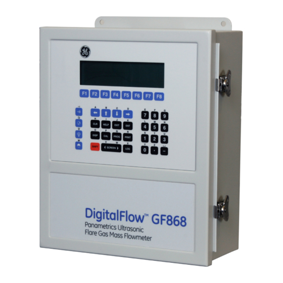
April 2004 Process Control Instruments Model GF868 Ultrasonic Flowmeter for Flare Gas (1-channel) User’s Manual 910-194P1B1... - Page 3 (RA), and shipping instructions for the return of the instrument to a service center will be provided. 2. If GE Panametrics instructs you to send your instrument to a service center, it must be shipped prepaid to the authorized repair station indicated in the shipping instructions.
-
Page 4: Table Of Contents
March 2003 Table of Contents Chapter 1: Programming Site Data Introduction ..............1-1 Using the Keypad . - Page 5 March 2003 Table of Contents (cont.) Saving Site Data............. 1-35 Recalling a Site .
- Page 6 Checking the GF868 Baud Rate ........
- Page 7 Adding the GF868 ........
- Page 8 Chapter 1...
- Page 9 Programming Site Data Introduction ......... . .1-1 Using the Keypad .
-
Page 10: Chapter 1: Programming Site Data
March 2003 Introduction The Model GF868 flowmeter cannot provide accurate flow rate measurements until the instrument has been properly installed and the basic system and pipe parameters have been programmed into the meter. See the Startup Guide for detailed instructions on performing these tasks. -
Page 11: Using The Keypad
March 2003 Using the Keypad The Model GF868 keypad contains 39 keys, which are labeled with their primary (unshifted) functions. In addition, pressing the red key will access the secondary functions assigned to most of [SHIFT] the keys. The complete keypad is illustrated in Figure 1-1 below and a detailed description of both the unshifted and shifted functions for each of the 39 keys is listed in Table 1-1 on page 1-3. - Page 12 March 2003 Table 1-1: Model GF868 Key Functions Unshifted Function Shifted Function Software Function Keys - press to None select the functions displayed directly above them in the option bar. These keys apply only to the left pane of the display screen.
- Page 13 March 2003 Table 1-1: Model GF868 Key Functions (Continued) Unshifted Function Shifted Function Display Key - use to display data in a Use to enter the letter O. variety of numeric and graphic format- ting options. See the Programming Manual for details.
- Page 14 March 2003 Table 1-1: Model GF868 Key Functions (Continued) Unshifted Function Shifted Function Two Key - use to enter the number 2. Use to enter the letter T. Three Key - use to enter the number 3. Use to enter the letter U.
-
Page 15: Obtaining On-Line Help
• Press ) to access this function, and the ERROR: [F3] [F7] various Model GF868 error codes are displayed. Use the [F1] [F4] [F5] [F8] ) function keys, in conjunction with the [←] and [→] keys, to obtain additional information on the desired error code or to exit the help system. -
Page 16: Using The Console Control Keys
March 2003 Using the Console The Model GF868 has four console control keys, which are located on the left side of the keypad. Use these keys, which are described Control Keys and pictured in Table 1-1 on page 1-3, in accordance with the following instructions: 1. -
Page 17: Entering Programming Mode
ACTIV SYSTM PIPE for operation of the Model GF868. Failure to accurately enter all of the required information will result in unreliable flow rate data. Therefore, be sure to complete at least the sections of this chapter pertaining to those three submenus. -
Page 18: Activating The Channel
The meter will exit the submenu and return to the ACTIV channel menu screen. The Model GF868 flowmeter can take measurements in two different ways: • Skan is a low resolution technique for locating the acoustic signal and for high velocity measurements. It is more robust in a noisy environment than the Measure technique. -
Page 19: Entering System Data
March 2003 Entering System Data 1. At the User Program screen, press the [F2] function key to program the submenu. SYSTM 2. Enter a Site Label of up to 9 characters and press [ENT] . (While taking measurements, the site label will appear on the locator bar.) 3. -
Page 20: Entering Totalizer Data
March 2003 Entering Totalizer Data 10.Use the [F1]-[F4] and [→] keys to select the Totalizer Units. The abbreviations and definitions of all the available volumetric and totalizer units are shown in Table 1-3 above. The choices shown on the option bar are determined by the selection made at the previous prompt screen. -
Page 21: Entering Pipe Data
The meter can not transmit an excitation voltage at the transducer’s natural frequency without this data. c. Enter the special transducer Time Delay (Tw) value supplied by GE Panametrics. Press . (The meter will only accept [ENT] values from 0 to 1000 µsec.) Note: Tw is the time required for the transducer signal to travel through the transducer and its cable. -
Page 22: Pipe Wall
OD. If the pipe wall thickness is not available, look up the value in a table of standard pipe size data or use the Model GF868’s on-line Help Menu (see the Programming Manual for details). -
Page 23: What's Next
March 2003 Entering K-Factors IMPORTANT: When editing the K-factor table, the velocities must be entered in increasing order. (cont.) c. Enter the Velocity Value for K-factor number “x”. Press [ENT] (The meter will only accept values from –30,000 to +30,000 ft/ sec.) d. -
Page 24: Setting Up Inputs/Outputs
March 2003 Setting Up Inputs/ Set up the GF868’s inputs and outputs via the four options in the submenu. While following the programming instructions, refer to Outputs Figure A-2 on page A-2 of Appendix A, Menu Maps. • - program the meter’s response during an error condition ERROR •... -
Page 25: Setting Up Analog Outputs
March 2003 Setting Up Analog The Model GF868 has two built-in analog outputs, which are assigned to . Also, a variety of option cards may be installed in Outputs Slot 0 the six expansion slots. See Chapter 1, Installation, of the Startup Guide for a complete description of the available option cards. -
Page 26: Option Card Alarms
March 2003 Setting Up Analog DIAG option provides access to a wide variety of diagnostics parameters. See Chapter 3, Diagnostics, of the Service Manual for a Outputs (cont.) complete description of these options. 4. Enter the Zero value for the low end of the chosen output range. Press [ENT] 5. -
Page 27: Setting Up Thetotalizer/Frequency Outputs
March 2003 Setting Up theTotalizer/ 1. Press [F1]-[F4] to set up outputs A, B, C or D, respectively. Frequency Outputs 2. Press = OFF to disable output A and return to the previous [F1] = TTLZR to designate output prompt, or press [F2] = FREQ or [F3] A as a frequency or a totalizer output, respectively. -
Page 28: Setting Up The Analog Inputs
March 2003 Setting up the Analog to set up input A or [F2] to set up input B. 1. Press [F1] Inputs Note: The set up of input A is used as an example in this manual. Identical procedures would be used to set up input B. (An analog input option card may contain one standard analog input and one RTD analog input.) 2. -
Page 29: Setting Up Rtd Inputs
Entering the Zero Cutoff Near zero flow, the Model GF868’s readings may fluctuate due to small offsets caused by thermal drift or similar factors. To force a zero reading when there is minimal flow, enter a zero cutoff value as described below: 1. -
Page 30: Setting Up Temperature And Pressure Inputs
March 2003 Setting Up Temperature The Model GF868 can use either fixed temperature and pressure quality values or live measurement inputs to calculate standard and Pressure Inputs volumetric or mass flow. Complete the following steps to configure these inputs: 1. At the main I/O menu prompt, press [F4] =T,P. -
Page 31: What's Next
March 2003 • Entering the Pressure If you selected SLOT X, Input (cont.) a. Press to select input A or press to select input B.The [F1] [F2] inputs were labeled during setup. b. Enter the Base Pressure (standard) value for the process, and press the key. -
Page 32: Entering Setup Data
March 2003 Entering Setup Data The signal limits and response times for the Model GF868 are specified via the submenu. While following the programming SETUP instructions, refer to Figure A-3 on page A-3 of Appendix A, Menu Maps. The following three submenus are included in this section: •... - Page 33 IMPORTANT: Consult the factory before performing this step. The amplitude discriminator measures the size of the transducer signal received by the Model GF868. The default value for this parameter is 14 and values from 0 to 100 are acceptable. The...
- Page 34 IMPORTANT: Consult the factory before performing this step. The amplitude discriminator measures the size of the transducer signal received by the Model GF868. The default value for this parameter is 34 and values from 0 to 100 are acceptable. The...
- Page 35 [ENT] IMPORTANT: Consult the factory before performing this step. Normally, the Model GF868 calculates the size of the transmit window based on pipe size and fluid sound speed. However, for special diagnostic purposes, it may sometimes be necessary to reset the window size.
- Page 36 [ENT] IMPORTANT: Consult the factory before performing this step. Normally, the Model GF868 calculates the size of the receive window based on pipe size and fluid sound speed. However, for special diagnostic purposes, it may sometimes be necessary to reset the window size.
- Page 37 March 2003 Setting Signal Limits Table 1-5: Default Values and Limits for GF868 (cont.) SETUP Parameters Parameter Default Value Low Limit High Limit Signal Low Limit Cor. Peak Limit Velocity Low -275.0 ft/sec -500 ft/sec +500 ft/sec Limit (- 85 m/sec)
-
Page 38: Setting Response Time
STATS response time under steady flow conditions while still allowing a rapid response to changes in flow rate. The GF868 program returns to the SETUP window. Remember to record all programmed data in Appendix B, Data Records. Initializing the System... -
Page 39: Setting The Clock
March 2003 Setting the Clock Use the CLOCK submenu to enter the current date and time. Refer to Figure A-3 on page A-3. 1. To program the CLOCK submenu, press [→] and [F2] at the initial User Program. Setting the Date 2. -
Page 40: What's Next
March 2003 What’s Next? After completing the above steps, the meter returns to the User Program. Continue as follows: • To continue programming the meter, refer to the menu maps in Appendix A and navigate to the desired menu. Then, proceed to the appropriate section of this manual for instructions. -
Page 41: Setting Up Serial Communications
March 2003 Setting Up Serial The Model GF868 flowmeter can transmit stored data and displayed readings to a remote ANSI terminal or a personal computer by Communications connecting the meter’s RS232 interface to the serial port of the PC. In addition, the Model GF868 can receive and execute remote commands via this link. -
Page 42: Entering Modbus Data
Only registers 1 through 90 are available for MODBUS communications, while registers 508 through 512 are used by the GF868 to store the MODBUS parameters. For details, see Table 1-7 on the next page. -
Page 43: Notes
March 2003 Table 1-7: MODBUS Registers for a 1-Channel GF868 MODBUS Scaling Reg # Hex Addr Description (decimal places) Size in Bytes 1” 2 (16 bit signed) Clear Ch1 Totalizers” Not Used 2 (16 bit signed) Velocity 4 (2 16-bit int) -
Page 44: Saving Site Data
Saving Site Data The currently programmed site data may be stored in the Model GF868’s non-volatile memory by saving it as a site file. Up to ten site file names, consisting of up to five characters each, may be stored at any given time. -
Page 45: Recalling A Site
COMM with the site file. Note: If you have loaded a site file into a GF868, but the option cards are not in the same slots or programmed the same way as when the site file was first saved, the GF868 displays a warning to review slot information. -
Page 46: Activating Security
[CLR] When the system is locked, access to the above menus will be denied unless the correct password is entered. The Model GF868 is shipped with a default password, which is given later in this section. For increased security, the default password should be changed. -
Page 47: What's Next
March 2003 The SECUR Submenu 4. Enter the New Password and press [ENT] . Any combination of letters and numbers up to a total of 21 characters may be used as a (cont.) password. Note: Keep in mind that the password may have to be entered frequently from the keypad. - Page 48 Chapter 2...
- Page 49 Displaying Data Introduction ......... . .2-1 The BIG Submenu .
-
Page 50: Introduction
- blanks out the display screen until a key is pressed. SLEEP Refer to Figure A-4 of Appendix A, Menu Maps, and proceed to the appropriate section to set up the Model GF868 display screen(s), using one of the listed submenus. Displaying Data... -
Page 51: The Big Submenu
March 2003 The BIG Submenu format, which is the Model GF868’s default power up format, displays one measurement in large print. To select the format and the measurement to display in this format, follow the instructions in this section. Upon power up, a standard measurement mode display (similar to the one shown below) appears. -
Page 52: The Dual Submenu
March 2003 The DUAL Submenu DUAL format displays two measurements simultaneously in normal print. To select the format and the measurements to DUAL display in this format, follow the instructions in this section. Upon power up, a standard measurement mode display (similar to the one shown below) appears in format. -
Page 53: The Graph Submenu
Y values. [F2] After the is entered, the Model GF868 automatically Y RANGE begins taking measurements and displays them in the specified graphical format. Proceed to the next section for a discussion of manipulating the graphical display. -
Page 54: Using The Graph Format
March 2003 Using the GRAPH While viewing data in the GRAPH format, the function keys are programmed to permit a variety of actions. These options are Format described in detail below. 1.23 Ft/s 10:16 Use the [←], [→] and [F1]-[F4] keys to select the desired option. - Page 55 March 2003 Using the GRAPH Table 2-2: Graph Display Options Format (cont.) Option Bar Choice Description Moves the cursor to the left and displays [F1] <CURS the corresponding measurement value and time in the status line: (i.e. 6.85 Ft/s 10:38 [F2] CURS>...
-
Page 56: The Log Submenu
The LOG Submenu submenu permits the display of the data in a log file either graphically or numerically. Although the Model GF868 can display all of the data in a log file, screen size limitations prevent the simultaneous display of the complete log file. Therefore, the function keys must be used to view the remaining data. -
Page 57: Numeric Format
March 2003 Numeric Format The Model GF868 can log up to three parameters simultaneously. Each set of data values is called a record, and up to 120 consecutive records can be stored in a page. A log file can consist of up to 120 pages. -
Page 58: Graphical Format
[F1] or press [F2] to graph both positive and negative Y values. After the is entered, the Model GF868 automatically Y RANGE displays the chosen log file records in the specified graphical format. 1.23 Ft/s 10:16 Use the [←], [→] and [F1]-[F4] keys to select the desired option. - Page 59 March 2003 Table 2-4: Graphical Log Display Options (Continued) Option Bar Choice Description →] + [F1] START Move the cursor to the first record on the current page and post the date and time of that record in the message line: (i.e.
-
Page 60: Displaying The Transducer Signal
March 2003 Displaying the The SIGNL submenu permits the direct graphical display of several transducer signals. Specifically, the signals listed in Table 2-5 below Transducer Signal may be viewed in this format. Table 2-5: Available Transducer Signals Transducer Signal Description Skan Types upstream Skan signal Sdown... - Page 61 March 2003 Displaying the 686.798mi Transducer Signal Use the [←], [→] and [F1]-[F4] keys to select the desired option. (cont.) The options are listed in Table 2- 6 below. ST: 594.298usec <CURS CURS> <PAGE PAGE> The typical display screen shown has the transducer signal listed to the left of the y-axis and there is a message line below the graph that initially indicates the starting date and time of the graphed signal.
- Page 62 March 2003 Displaying the In addition to the functions available on the option bar, some of the numeric keys are used to specify which transducer signal is displayed Transducer Signal and to scale the resulting graph. Table 2-7 below lists these functions. (cont.) Table 2-7: Numeric Key Functions Function...
-
Page 63: Setting The Lcd Backlight
. To keep the backlight on constantly, enter a value of 0 and press [ENT] The Model GF868 will automatically return to the previous data display screen and the programmed backlight timeout interval will begin. If no entries are made from the keypad before the backlight timeout interval expires, the backlight will automatically be turned off. -
Page 64: Activating Sleep Mode
During times when the display is not in use, use the SLEEP submenu to temporarily suspend LCD display activity, which allows the Model GF868 to process data more quickly. Press the appropriate side of the [SCREEN] key to activate the desired pane of the display screen, then proceed as follows: Note: For this discussion, it is assumed that the left pane of the display screen is active. - Page 65 Chapter 3...
- Page 66 Logging Data Introduction ......... . .3-1 Creating a Standard Log .
-
Page 67: Introduction
Error logs record data only when an error message is generated. The Model GF868 allocates up to 120 pages of memory, each of which can contain up to 120 records, for data logging. Each page is assigned a header, to distinguish one page from another. -
Page 68: Creating A Standard Log
Recall that a flashing asterisk (*) appears at the far right of the locator bar if the Model GF868 is currently logging data (see Chapter 3, Operation, of the Startup Guide). -
Page 69: Log Type
March 2003 Creating a Standard Refer to Chapter 3, Diagnostics, of the Service Manual for a discussion of the many parameters accessible via the option. DIAG Note: The units assigned to the parameters in Table 3-1 on the previous page are those selected in the User Program ( SYSTM submenu). -
Page 70: Start Date Prompt
March 2003 STARTTIME Prompt a. Press [F1]-[F2] to select . Then, enter the desired Hour (1-12) and press . (Entry of a start time earlier than (cont.) [ENT] the current time will generate an error message.) b. Enter the desired Minutes and press [ENT] . -
Page 71: End Date Prompt
March 2003 END TIME Prompt a. Press [F1]-[F2] to select . Then, enter the desired Hour (1-12) and press . (Entry of a start time earlier than (cont.) [ENT] the current time will generate an error message.) b. Enter the desired Minutes and press [ENT] . -
Page 72: Time Increment Prompt
Increment. The available options are: 5sec, 10sec, 30sec, 1min, 3min, 6min, 12min, 30min and 60 min. The time increment is the frequency at which the Model GF868 takes and records data measurements. If any reading takes longer than the programmed time increment, the log is filled in with the next consecutive reading. -
Page 73: Checking The Memory
If the expected amount of logged data will exceed the remaining memory capacity, the Model GF868 suggests that some old logs be cleared to make room for the new log. -
Page 74: Stopping A Log
Recall that a flashing asterisk (*) appears at the far right of the locator bar if the Model GF868 is currently logging data (see Chapter 3, Operation, of the Startup Guide). -
Page 75: Creating An Error Log
Note: The option bar lists all error logs currently stored in memory. Recall that a flashing asterisk (*) appears at the far right of the locator bar if the Model GF868 is currently logging data (see Chapter 3, Operation, of the Startup Guide). -
Page 76: Log Type
March 2003 Creating an ERROR In addition, refer to Chapter 3, Diagnostics, of the Service Manual for a discussion of the many parameters accessible via the option. Log (cont.) DIAG Note: The units assigned to the parameters in Table 3-2 on the previous page are those selected in the User Program ( SYSTM submenu). -
Page 77: Start Date Prompt
[ENT] key. The * on the locator bar indicates that the Model GF868 is now compiling the specified error log. The error log will continue to run until it is manually stopped, the meter runs out of memory (for a non-circular log), or the entire 120 records (2 pages x 60 records/page) have been logged. - Page 78 Chapter 4...
- Page 79 Printing Data Introduction ......... . .4-1 Print Live Data .
-
Page 80: Introduction
March 2003 Introduction The Model GF868 flowmeter has the capability to print any of the data stored in its memory via the built-in RS232 communications port. In order to use the function, the RS232 port must be connected to a printer with a serial port input. A printer with a parallel port input may be used with a third-party serial-to-parallel adapter. -
Page 81: Print Live Data
March 2003 Print Live Data Use the DATA submenu to print live measurement data, as it is collected. The data may be printed in either numeric or graphical format, with a user specified time increment. IMPORTANT: Make sure that a printer has been properly set up before proceeding with this section. -
Page 82: Graphical Format
5sec, 10sec, 30sec, 1min, 3min, 6min and 12min. After the time increment is chosen, the Model GF868 returns to the standard data display screen and continues to take measurements. The live data is printed at the specified time intervals, until a... - Page 83 5sec, 10sec, 30sec, 1min, 3min, 6min and 12min. After the time increment is chosen, the Model GF868 returns to the standard data display screen and continues to take measurements. The live data is printed at the specified time intervals, until a...
-
Page 84: Printing Logs
Numeric Format After the numeric format (and starting page and number of pages, if applicable) is chosen, the Model GF868 returns to the standard data display screen and begins printing the log file. The printout continues until the entire log has been printed or until a... -
Page 85: Graphical Format
[F2] to display both the positive and negative y axis. The Model GF868 returns to the standard data display screen and begins printing the log file. The printout continues until the entire log has been printed or until a... -
Page 86: Print Site File
The active site file is always listed as the first choice (Work) The Model GF868 returns to the standard data display screen and generates a site file printout similar to the one shown in Figure 4-5 on page 4-11. The printout continues until the entire file has been printed... -
Page 87: Stop Printing
Either wait for the printer to finish or turn the printer off to empty the buffer immediately. The Model GF868 returns to the standard data display screen and normal measurement taking. Printing Data... -
Page 88: Setting Up A Printer
PRNTR submenu to specify the type of printer connected to the Model GF868. To set up a printer, refer to Figure A-5 on page A-5 of Appendix A, Menu Maps, and complete the following steps: IMPORTANT: A printer must be properly set up before proceeding to any of the other sections in this chapter 1. -
Page 89: Printing Signal Array Data
The option prints both sets of data. BOTH After the desired print selection has been made, the Model GF868 returns to the standard data display screen and normal measurement taking. The specified signal array data is printed continuously, until it is manually stopped. - Page 90 March 2003 Printing Signal Array The data printed via the SIGNL submenu consists of 1024 lines, each of which lists the following three values: Data (cont.) • - this is the printout line number, which locates the data Index point within the complete body of data. •...
-
Page 91: Printing Rtd Data
RTD data to the [F2] RS232 port. After the selection has been made, the Model GF868 returns to the standard data display screen and normal measurement taking. If you have selected YES at the DUMP RTD DATA prompt, the meter continues to send data until you reenter the PRINT menu and select the STOP option. - Page 92 Chapter 5...
- Page 93 Clearing Data Introduction ......... . .5-1 Reset Totals .
-
Page 94: Introduction
March 2003 Introduction This chapter explains how to purge the Model GF868’s memory of various measurement totals and/or files. The Clear Menu, which is accessed by pressing the key on the keypad, is divided into [CLR] three submenus: • - used to reset totalized measurement values TOTAL •... -
Page 95: Reset Totals
March 2003 Reset Totals TOTAL submenu permits the user to reset volumetric totals to zero and to reset the stopwatch totalizer. Press the appropriate side of key to activate the desired pane of the display screen, [SCREEN] and complete the following steps: 1. -
Page 96: Deleting Site Files
March 2003 Deleting Site Files Use the SITE submenu to clear site files from the GF868’s memory. Use the key to activate the desired display pane, and [SCREEN] complete the following steps: 1. To access the Clear Menu, press the [CLR] key. -
Page 97: Deleting Log Files
March 2003 Deleting Log Files Use the submenu to clear log files from the Model GF868’s memory. Press the appropriate side of the key to activate [SCREEN] the desired pane of the data display screen, and complete the following steps: 1. - Page 98 Chapter 6...
-
Page 99: Serial Communications
Wiring the RS232 Interface .......6-1 Checking the GF868 Baud Rate ......6-2 Setting Up the Terminal Software . -
Page 100: Introduction
• Transfer the log files to the personal computer. Wiring the RS232 The first step is to connect the built-in RS232 port in the GF868 to one of the serial ports (COM1 or COM2) on the personal computer. Interface Table 6-1 below lists the standard cables available from GE Panametrics for this purpose. -
Page 101: Setting Up The Terminal Software
For successful serial communications, the GF868 and the personal computer must be set up to send/receive data at the same speed. To Baud Rate verify or change the baud rate setting of the GF868, proceed as follows: Access the User Program, by pressing the... -
Page 102: Windows 9X/Nt Systems
To set up serial communications with a Systems personal computer running under Windows 95, Windows 98 or Windows NT, make sure the GF868 is powered on and complete the following steps: 1. From the Windows START menu, select PROGRAMS>... -
Page 103: The Optional Rs485 Serial Interface
Interface Converter A special bracket containing the serial interface converter and a three- terminal barrier strip is mounted inside the Model GF868, just below Mounting the RS232 terminal block (see Figure 6-1 below). The standard terminal block is wired to the input of the serial interface... -
Page 104: Point-To-Point Wiring
Point-To-Point Wiring Standard factory wiring of the RS485 serial interface is configured for point-to-point wiring. That is, a single Model GF868 may be wired directly to a single personal computer. To connect the RS485 serial interface, refer to Figure 6-1 on the previous page and complete the following steps: Note: For compliance with the European Union’s Low Voltage... -
Page 105: Multi-Point Wiring
April 2004 Multi-Point Wiring The standard point-to-point wiring configuration for the serial interface converter may be modified to permit the use of a multi-point wiring arrangement. In a multi-point RS485 system, one flowmeter (the master) is connected to the personal computer, while a number of additional flowmeters (the slaves) are chained together and connected to the master flowmeter. - Page 106 April 2004 Reconfiguring a Serial Interface Converter (cont.) Plastic Case Mounting Screw Screwdriver DB9 Connector Figure 6-2: Opening the Converter Case Table 6-3: Switch Assembly Settings Position # Point-To-Point Multi-Point 7. Reassemble the serial interface converter and secure it to the mounting bracket with the two mounting screws.
- Page 107 The RS485 serial interface is now ready for multi-point operation. However, the installed version of the Model GF868 software must support RS485 operation for the interface to work properly. If necessary, contact the factory for information about a software upgrade.
- Page 108 Appendix A...
- Page 109 Menu Maps The ACTIV, SYSTM and PIPE Submenu Map ....A-1 The I/O Submenu Map ........A-2 The PROG Menu Map.
- Page 110 March 2003 PROGRAM status ACTIV SYSTM PIPE SITE LABEL Site status TRANSDUCER NUMBER BURST SITE MESSAGE SPEC SYSTEM UNITS Skan/Measure Mode SPECIAL TRANSDUCER # METRC FREQUENCY Skan PRESSURE 100k 200k 500k UNITS [English] [Metric] BARg BARa PSIa PSIg PIPE OD [English] [Metric] KPag...
- Page 111 March 2003 PROGRAM status ACTIV SYSTM PIPE SETUP CLOCK COMM SAVE RECLL SECUR OPTN ZERO ERROR ZERO CUTOFF ERROR HANDLING SLOT0 SLOTX HOLD HIGH HHIGH OTHER TEMP INPUT Slot 0 - Analog Outputs Slot x (Option Card) Slot x - Freq/Total Outputs FIXED SLOTX Slot x - Analog Outputs...
- Page 112 March 2003 PROGRAM status ACTIV SYSTM PIPE SETUP CLOCK COMM SAVE RECLL SECUR SET UP LOCK OUT SIGNL AVRG INIT UNlck LOCK ENTER PASSWORD Press YES to Default ? EDIT PASSWORD SIGNAL LOW LIMIT DATE ENTER NEW PASSWORD COR. PEAK LIMIT VERIFY NEW PASSWORD EDIT YEAR...
- Page 113 March 2003 DISPLAY FORMAT DUAL GRAPH SIGNL BACKL SLEEP LCD SLEEP MODE Backlight timeout NAME LOG1 LOG2 LOG3 LOG4 FORMAT PLOT GRAPH VARIABLE Y AXIS MAX Y RANGE VOLUM MDOT +only TIME INCREMENT 5sec 10sec 30sec 1min 3min 6min 12min NUMERIC LOG GRAPHICAL LOG Y AXIS MAX...
- Page 114 March 2003 PRINT DATA PROG STOP PRNTR SGNLS RTDs FORMAT FORMAT PLOT PLOT 1st value printed NAME STOP PRINTING Printer Type DUMP RTD DATA VOLUM +TOTL -TOTL MDOT +MASS -MASS DIAG LOG1 LOG2 LOG3 LOG4 DP411 XTECH EPSON KODAK SP401 (NUM option) (PLOT option) (log>1 page) (log=1 page)
- Page 115 March 2003 LOGGING CLEAR STOP ERROR TOTAL SITE X/120 Pages FREE NAME CLEAR TOTALS SITE NAME NAME Y Pages PENDING LOG1 LOG2 LOG3 LOG4 SITE1 SITE2 SITE3 SITE4 LOG1 LOG2 LOG3 LOG4 Stop Logging ? CLEAR SITE NAME CLEAR NAME (if no more files) (if more files) (if no more files)
- Page 116 Appendix B...
-
Page 117: Appendix B: Data Records
Data Records Option Cards Installed ........B-1 Initial Setup Data . -
Page 118: Option Cards Installed
March 2003 Option Cards Installed Whenever an option card is installed in one of the Model GF868’s expansion slots, record the type of card and any additional setup information in the appropriate row of Table B-1 below. Table B-1: Option Cards Installed... -
Page 119: Initial Setup Data
March 2003 Initial Setup Data After the Model GF868 flowmeter has been installed, some initial setup data must be entered via the User Program, prior to operation. Record that information in Table B-2 below. Table B-2: Initial Setup Data General Information... - Page 120 Appendix C...
- Page 121 Adding the GF868........
-
Page 122: Appendix C: Programming With Panaview
Windows-based PCs and GE Panametrics instruments compatible with the company’s IDM protocol, such as the GF868 ultrasonic gas flowmeter. PanaView is compatible with 32-bit Windows operating systems such as Windows 98SE, NT 4.0 (with Service Pack 6), 2000, XP and ME. With PanaView, you can: •... -
Page 123: Setting Up The Communications Port
April 2004 Setting Up the Use the steps below to establish communications with the GF868. Communications Port 1. Open the “New Meter Browser” window and expand the network tree. Then, highlight the My Computer(Name) branch by clicking on it. 2. Pull down the “Edit” menu by clicking on it in the menu bar. - Page 124 April 2004 Setting Up the 4. Click on the “Communications Port” option to select it. The Setup Communications screen appears similar to Figure C-2 below. Communications Port (cont.) Figure C-2: Setup Communications Screen 5. Open the Protocol menu (the first of the drop-down menus) and click on IDM.
-
Page 125: Adding The Gf868
April 2004 Adding the GF868 To add the GF868 on the IDM-configured communications port, complete the following steps: 1. Highlight the communication port to which the meter will be added by clicking on it, and then open the “Edit” menu on the menu bar (if the communication port is not highlighted first, the “New Meter”... - Page 126 April 2004 Adding the GF868 IMPORTANT: The Network ID number must match the Network ID programmed in the meter’s Communications menu. (cont.) If the initialization is successful, the Meter Browser shows a listing similar to Figure C-5 below. Figure C-5: The Updated Network Tree Note: The model number and version that appear will vary with your particular meter and software version.
-
Page 127: Editing Meter Properties
April 2004 Editing Meter Through PanaView, you can edit the properties of your GF868. You can: Properties • Set the meter clock, or synchronize it with the PC clock • Read, plot and save transducer signals • Clear totalizers •... - Page 128 April 2004 Editing Meter The window appears similar to Figure C-8 below. To perform a specific task, refer to the appropriate section on the following pages. Properties (cont.) • Setting the Meter Clock (page C-8) • Reading Transducer Signals (page C-9) •...
-
Page 129: Setting The Meter Clock
April 2004 Setting the Meter Clock The meter’s Time may be reset in three different ways: • manually enter the time and date in the text box, or • click on the option button to have PanaView set [Sync to PC] the time and date to the current PC setting, or •... -
Page 130: Reading Transducer Signals
April 2004 Reading Transducer To read a Signal from the meter: Signals 1. Click on the Read Signals button. (If the meter is a multi-channel instrument, open the Channel drop-down menu and click on the desired channel.) After a moment, the Properties window appears similar to Figure C-10 below. -
Page 131: Saving Transducer Signals
April 2004 Saving Transducer To save the raw signal, click Save. A window opens similar to Figure C-12 below. Enter the desired name, and click Save to save the signal Signals as a text file. Figure C-12: Save As Window Clearing Totalizers To clear the meter totalizers, click on the Clear Totalizers button in the Properties window. -
Page 132: Handling Site Files
April 2004 Handling Site Files To access site files, click on the Site Files button in the Properties window. The Site File Operations window (shown in Figure C-13 below) opens. Figure C-13: The Site File Operations Window Saving an Existing Site To save an existing site to the meter: to the Meter 1. - Page 133 April 2004 Saving a New Site to the To save a new site to the meter: Meter 1. Select the radio button for New and click on the Save Site to Meter button. 2. A window opens similar to Figure C-15 below. Enter the desired name, and click [OK].
- Page 134 April 2004 Clearing a Site from the To clear a site from the meter: Meter 1. Highlight the site in the left pane. (See Figure C-13 on page C-11.) 2. Click Clear Site From Meter. 3. The program asks for confirmation. Click [OK]. The meter deletes the designated file.
-
Page 135: Changing Meter Settings
April 2004 Changing Meter Through PanaView, GF868 users can handle remote programming of the meter. They can: Settings • Program and change a meter’s operating parameters; • Set up, start, and stop logs; • Calibrate and test inputs and outputs;... - Page 136 Note: The options listed in the left pane correspond to the options available in the GX868 PROGRAM menus. For more information about the options in your instrument program and about appropriate parameters for the GF868, consult the previous chapters in this manual. Programming with PanaView...
- Page 137 April 2004 Changing Meter 6. To enter a particular option: Settings (cont.) a. Highlight and double-click on the desired option in the left pane. Figure C-20 below shows the first entry (Transducer Number) in the Pipe parameters option. The title above the center pane lists the current entry, while the center pane displays the available selections for that entry.
- Page 138 April 2004 Changing Meter Settings (cont.) Figure C-21: Site Edit Menu with Current Settings 7. When you have completed entering parameters in a given option, click to close the option. You can then double-click on [Exit Page] another option, or click [Close] to close the window.
- Page 139 April 2004 Index Abbreviations, Volumetric Units ..1-10 DATA ACTIV Submenu ......4-2 Menu Map .
- Page 140 April 2004 Index (cont.) GRAPH Screen Display Options ....2-6 Entering the Submenu ....2-7 Screen Format .
- Page 141 April 2004 Index (cont.) On-Line Help ......1-6 PanaView ......1-32 Option Card PanaView, Applications of .
- Page 142 April 2004 Index (cont.) RECLL Entering......1-36 Submenu ......1-36 RS232, RS485 See Serial Interface RTD Inputs Card, Setting Up .
- Page 143 Menu Map ......4-8 GE Panametrics Cables ....6-1 Submenu .
- Page 144 April 2004 Index (cont.) Uploading Logs Windows 9X/NT..... 6-3 User Program Data Record ..... . . B-2 Entering.
- Page 145 Shannon, Co. Clare Ireland declare under our sole responsibility that the DF868 Liquid Ultrasonic Flowmeter GF868 Flare Gas Ultrasonic Flowmeter GM868 Multi-Purpose Gas Ultrasonic Flowmeter GN868 Natural Gas Ultrasonic Flowmeter GS868 Steam Mass Ultrasonic Flowmeter to which this declaration relates, are in conformity with the following standards: •...
- Page 146 Shannon, Co. Clare Ireland déclarons sous notre propre responsabilité que les DF868 Liquid Ultrasonic Flowmeter GF868 Flare Gas Ultrasonic Flowmeter GM868 Multi-Purpose Gas Ultrasonic Flowmeter GN868 Natural Gas Ultrasonic Flowmeter GS868 Steam Mass Ultrasonic Flowmeter rélatif á cette déclaration, sont en conformité avec les documents suivants: •...
- Page 147 Shannon Industrial Estate Shannon, Co. Clare Ireland erklären, in alleiniger Verantwortung, daß die Produkte DF868 Liquid Ultrasonic Flowmeter GF868 Flare Gas Ultrasonic Flowmeter GM868 Multi-Purpose Gas Ultrasonic Flowmeter GN868 Natural Gas Ultrasonic Flowmeter GS868 Steam Mass Ultrasonic Flowmeter folgende Normen erfüllen: •...
- Page 148 WORLDWIDE OFFICES MAIN OFFICES: GE PANAMETRICS INTERNATIONAL OFFICES: Australia Japan GE Panametrics P.O. Box 234 2F, Sumitomo Bldg. 221 Crescent St., Suite 1 Gymea N.S.W. 2227 5-41-10, Koishikawa, Bunkyo-Ku Waltham, MA 02453-3497 Australia Tokyo 112-0002 Telephone 61 (02) 9525 4055...
- Page 149 GE Panametrics 221 Crescent Street, Suite 1 Waltham, MA 02453-3497 Telephone: (781) 899-2719 Toll-free: (800) 833-9438 Fax: (781) 894-8582 E-Mail: panametrics@ps.ge.com Web: www.gepower.com/panametrics Ireland GE Panametrics Shannon Industrial Estate Shannon, County Clare Ireland Telephone: 353-61-470200 Fax: 353-61-471359 E-Mail: info@panametrics.ie...
Need help?
Do you have a question about the GF868 and is the answer not in the manual?
Questions and answers