Table of Contents
Advertisement
Quick Links
Advertisement
Table of Contents

Subscribe to Our Youtube Channel
Related Manuals for Lightware UMX4x4-Pro


Summary of Contents for Lightware UMX4x4-Pro
- Page 1 UMX4x4-Pro User’s Manual...
-
Page 3: Safety Instructions
SAFETY INSTRUCTIONS Class I apparatus construction. This equipment must be used with a mains power system with a protective earth connection. The third (earth) pin is a safety feature, do not bypass or disable it. The equipment should be operated only from the power source indicated on the product. -
Page 5: Table Of Contents
Multiple simultaneous connections ..................42 4.5.3. Serial port settings ........................42 4.5.4. IP settings ..........................42 4.5.5. Control protocols ........................42 SOFTWARE CONTROL – USING LIGHTWARE MATRIX CONTROLLER ......... 44 5.1................44 NSTALLING THE ATRIX ONTROLLER SOFTWARE Page 5 / 129... - Page 6 5.2......................45 STABLISHING THE CONNECTION 5.3..........................48 ONTROL MENU 5.3.1. Port status display ........................48 5.3.2. Input and output names ......................49 5.3.3. Quick I/O port information ......................49 5.3.4. Switch, mute and lock ......................49 5.3.5. Preset operations ........................50 5.3.6.
- Page 7 UMX4x4-Pro User’s Manual View router’s health ......................... 84 7.4.9. 7.4.10. View installed I/O boards ......................84 7.4.11. View error list ........................... 85 7.5..........................85 YSTEM COMMANDS 7.5.1. Reload factory defaults ......................85 7.5.2. Count HDCP keys ........................86 7.5.3.
- Page 8 7.10.12. Query analog input audio properties ..................105 7.10.13. Set the color of no sync picture ..................... 105 7.10.14. Query the color of no sync picture ..................105 7.10.15. Query timings of the incoming signal ..................105 7.11. O ........................106 UTPUT PROPERTIES 7.11.1.
-
Page 9: Introduction
Thank you for choosing Lightware UMX4x4-Pro matrix switcher. The UMX4x4-Pro router is able to switch 4 inputs to 4 outputs in a non-blocking crosspoint configuration. The UMX4x4-Pro, the all-round Universal Matrix Switcher, is the perfect solution for ever- changing environments such as small board rooms and classrooms. UMX (Universal MatriX) technology was recently developed by Lightware to support various analog and digital audio visual formats. - Page 10 DVI output to power long distance fiber optical cables. Zero frame delay – Even on Analog Inputs - Lightware’s UMX4x4-Pro add no frame noticeable delay to the switched signal. There is no frame or line period delays to the signals when passing a Lightware router.
-
Page 11: Typical Applications
UMX4x4-Pro User’s Manual 2.3. Typical applications Some typical connection variations with the matrix router are shown on Figure 2-1. Figure 2-1. Typical application for UMX4x4-Pro Application examples Small classrooms Conference rooms, collaborative telepresence Control room Multiroom video ... -
Page 12: Understanding Edid
HDMI capable which have the extension. 2.4.2. Common problems related to EDID Problem: „My system consists of the following: a computer, a Lightware UMX4x4-Pro matrix, a WUXGA (1920x1200) LCD monitor, and an SXGA (1280x1024) projector. -
Page 13: Advanced Edid Management
UMX4x4-Pro User’s Manual Problem: „I have a UMX4x4-Pro and I’m using a Lightware factory preset EDID. I would like to be able to choose from different resolutions, but my source allows only one resolution.” Solution: Most Lightware factory preset EDIDs allow only one resolution, forcing the sources to output only that particular signal. -
Page 14: Hdcp Management
2.6.2. HDPC key caching Lightware introduced the HDCP key cashing technique in early 2009 that validates all the display keys in an AV system during system boot up and keeps them constantly available for sources. -
Page 15: Pixel Accurate Reclocking
Without reclocking, sparkles, noise and jaggies can be seen on the image. Lightware’s sophisticated Pixel Accurate Reclocking technology fixes more problems than general TMDS reclocking. It removes not only intra-pair skew but inter-pair skew as well. - Page 16 Inter-pair skew: skew between two differential wire pairs in a cable. It’s caused by different wire pair lengths or different number of twists in the HDMI cable. Too much inter-pair skew results in color shift in the picture or sync loss. Jitter: signal instability in the time domain.
-
Page 17: Controls And Connections
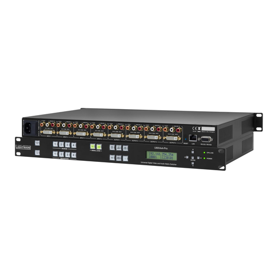
Status LEDs Function buttons Output lock Destination buttons Menu display Figure 3-1. UMX4x4-Pro front view Status LEDs POWER LED indicating that the unit is powered on and CPU LIVE blinking LED indicating normal operation. Menu navigation (UP, DOWN, LEFT, RIGHT, ENTER) buttons for menu navigation. -
Page 18: Umx4X4-Pro Rear View
Ethernet port Analog audio in Figure 3-2. UMX4x4-Pro rear view Inputs UMX4x4-Pro has 4 input ports. Each port has one video, one analog stereo audio and one digital audio input. DVI-I in Standard 29-pole DVI-I connectors for input connections. It accepts analog and digital signals. -
Page 19: Electrical Connections
Electrical connections 3.3.1. DVI inputs UMX4x4-Pro provides standard 29 pole DVI-I connectors for inputs. This way, users can plug in any DVI connector, but keep in mind that analog signals (such as VGA or RGBHV) are processed only on the DVI inputs. -
Page 20: Control Port
3.3.3. RS-232 control port UMX4x4-Pro can be remote controlled through industry standard 9 pole D-SUB female connector. The router can be ordered with RS 232 control port. Figure 3-4. D-SUB 9 pole female connector (DE9F) Pin nr. RS-232 NC - non connected... -
Page 21: Ethernet Port
LED1 LED2 Blink activity Figure 3-5. RJ45 receptacle connector Figure 3-6. RJ45 plug Lightware recommends the termination of TP cables on the basis of TIA/EIA T 568 A or TIA/EIA T 568 B standards. TIA/EIA color and TIA/EIA color Name... -
Page 22: Digital Audio Input And Output Connectors
3.3.5. Digital audio input and output connectors UMX4x4-Pro has standard RCA receptacles for digital coaxial audio inputs and outputs. RCA receptacle RCA plug Name S/PDIF input or output Plastic insulator Table 3-4. RCA connector pin assignments for digital audio Info Plugs and sockets on consumer equipment are conventionally color-coded by CEA/CEDIA- 863-B (ANSI) to aid correct connections. -
Page 23: Operation
UMX4x4-Pro User’s Manual 4. Operation 4.1. Power Connect the power cord to the router’s IEC C14 standard power input connector. The router is immediately powered ON when the power cord is connected to the AC source. During the initial self-test and loading of the latest settings ,,Booting…” appears on the LCD screen. -
Page 24: Sources And Destinations Buttons
4.2.4. SOURCES and DESTINATIONS buttons Input and output ports have dedicated buttons on the front panel. These buttons are labeled with numbers and have backlight to indicate active or selected ports. These are referred as SOURCES and DESTINATIONS buttons. 4.2.5. Viewing crosspoint state User can check the current switching status on the front panel using front panel buttons. -
Page 25: Switching
UMX4x4-Pro User’s Manual 4.2.6. Switching Creating connections in TAKE mode Step 1. Select the desired layer. (Video or audio or both of them) Step 2. Press and release the desired source button. The pressed source button and all destination buttons which are currently connected to this source will light up. The dark remaining destination buttons are not connected to this source. -
Page 26: Switching Operations Flowchart
4.2.7. Switching operations flowchart To better understand the viewing and switching sequence in TAKE and AUTOTAKE modes, please study the below diagrams. Switching sequences are the same with any layer selection. Info Layers can be selected or deselected whenever during the switching sequence. TAKE mode same all outputs... -
Page 27: Preset Operations
User’s Manual 4.2.8. Preset operations All Lightware matrices have 32 user programmable presets. Each preset stores a configuration regarding all input connections and mute state for all outputs and both of the layers. All presets are stored in a non-volatile memory; the router keeps presets even in case of power down. -
Page 28: Output Lock
4.2.9. OUTPUT LOCK Using Lightware routers it is possible to lock a destination’s state. This feature prevents an accidental switching to the locked destination in case of important signal. Locking a destination means, that no input change or muting can be executed on that particular destination. - Page 29 UMX4x4-Pro User’s Manual View locked outputs in AUTOTAKE mode In AUTOTAKE mode a destination is selected all the time. Therefore the currently selected output and input buttons are illuminated. The Output Lock button illuminates regarding to the lock state of the current output.
-
Page 30: About Edid Memory
The factory EDIDs (Fxx) are factory preprogrammed and cannot be modified. These are the most commonly used resolutions. Info: UMX4x4-Pro can handle both 128 Byte EDID and 256 Byte extended EDID structures. The attached monitor’s EDID is stored automatically, until a new monitor is attached to that Info: particular output. -
Page 31: Factory Edid List
UMX4x4-Pro User’s Manual 4.3.2. Factory EDID list Memory Resolution Type Memory Resolution Type 640 x 480 @ 60.0 Hz 720 x 480 @ 30.1 Hz Analog 848 x 480 @ 60.0 Hz 720 x 576 @ 25.3 Hz Analog 800 x 600 @ 60.30 Hz 640 x 480 @ 60.0 Hz... -
Page 32: Front Panel Lcd Menu Operation
4.4. Front panel LCD menu operation 4.4.1. Basic concept There are three operating modes of the LCD menu: Normal mode Most settings can be done in this mode. It is active when neither the EDID nor the SIGNAL PRESENT button lights. EDID mode Use this mode to set up the emulated EDID on the inputs, learn EDID form the outputs or to view the EDID memory. -
Page 33: Navigation
UMX4x4-Pro User’s Manual 4.4.3. Navigation The front panel LCD has 2 lines and 16 characters in each line. The left ◄ and right ► buttons can be used to scroll between menu items. The enter button steps in the submenus or makes changes available. - Page 34 Important: New IP settings can be applied while an active connection is alive on the Ethernet port but in this case the active connection will be closed automatically. To reconnect the Ethernet port needs to be used again. If you get ,,OPERATION FAILED” message then please disconnect the remote TCP/IP Info: sockets and try again.
- Page 35 UMX4x4-Pro User’s Manual Level Description Notice Not an error. Initialization information. Warning Possible problem without influencing normal operation. Matter Problem that may lead to further errors. Error Serious error. Must report to support. Fatal Fatal error. Normal operation is not possible.
- Page 36 Press the ENTER button to execute IP reset. Confirmation message will be appeared. The string to be shown is longer EDID reset? than LCD display line. Wait a second and the string will be Press ENTER to p shifted to left character by character. Press the ENTER ...
- Page 37 Phase If there is a phase reverse item in the amplifier chain analog audio signal can be compensated by changing the polarity in the UMX4x4-Pro. It can be set up manually to 0 degree (Normal) or 180 degree (Inverted) manually.
- Page 38 Navigate to the ‘Input 1 Return’ item then press the ENTER button to step back to the input port settings. 6) Navigate to the ‘Return’ item then press the ENTER Return button to step back to the main menu. Output settings Navigate to this menu in the main menu list.
-
Page 39: Edid Mode
UMX4x4-Pro User’s Manual HDCP keycounter This menu allows to test source devices how many HDCP keys they can accept. Select the input port with the up ▲ and down ▼ buttons, to which the HDCP keycounter tested device is connected to, and then press the ENTER ... -
Page 40: Signal Present Mode
Switch EDID menu Select ‘Switch EDID..’ menu items with the left ◄ and right ► Switch EDID.. buttons and then press ENTER to step in the submenu. The emulated EDIDs can be changed in this menu. Dynamic, User or Factory EDIDs can be selected in the top row with the up ▲... -
Page 41: Remote Operation
4.5. Remote operation Lightware matrix routers can be controlled through various interfaces remotely. This makes it possible to use functions that are not accessible via the front panel. Also, this helps system integrators and operators to control multiple devices in a big system through a single user interface. -
Page 42: Multiple Simultaneous Connections
Step 6. Wait about 5 seconds before connecting the router via Ethernet. 4.5.5. Control protocols Matrix routers can be controlled with multiple control protocols. Lightware routers have a special protocol, but to interoperate with third party devices, a secondary protocol is also provided. - Page 43 Step 3. Press and keep pressed the Output Lock button. Now the active protocol is displayed: (view protocol) One source button lights up according to the current protocol: Source#1 lights: Lightware protocol active on Serial Source#2 lights: Protocol#2 is active on Serial Step 4.
-
Page 44: Software Control - Using Lightware Matrix Controller
5. Software control – Using Lightware Matrix Controller The matrix router unit can be controlled using Lightware Matrix Controller from a Windows PC or Laptop through RS-232 or Ethernet port. 5.1. Installing the Matrix Controller software Step 1. Run Installer_LW_matrix_controller_v3_3_9.exe Step 2. -
Page 45: Establishing The Connection
UMX4x4-Pro User’s Manual Step 5. To run Lightware matrix control software find the shortcut icon in Start menu Programs Lightware LW_matrix_controller_v3.3.9 or on the desktop, and double click: Uninstalling To uninstall the control software double click on: Start menu Programs Lightware ... - Page 46 If the connection has been made via Ethernet, the software picks the primary Ethernet interface, and shows the available Lightware devices on that port. The device type and the serial number are displayed automatically. Click the desired device, to highlight it.
- Page 47 Info: Be sure that the firewall is not blocking the application! When the Lightware Matrix Controller finds the hardware, it determines the product type, and the control menu appears. The current state of the crosspoint switch is displayed. Section 5. Software control – Using Lightware Matrix Controller...
-
Page 48: Control Menu
+5V is present from the source; Hotplug is present (source connected) DVI signal is present HDMI signal is present Analog signal is present Section 5. Software control – Using Lightware Matrix Controller Page 48 / 129... -
Page 49: Input And Output Names
Section 5. Software control – Using Lightware Matrix Controller Page 49 / 129... -
Page 50: Preset Operations
Preset operations can be done on the PRESET panel. The panel can be accessed by clicking on the vertical ‘Preset’ label at the right margin of the software window. Each Lightware matrix switcher has 32 preset memories that can be loaded and saved at any time. -
Page 51: Input Parameter Settings
When opening this window again, the scope selection will be set to “Current Input” Info: regardless of the active selection at the time of closing. It is to avoid making changes to all inputs by mistake. Section 5. Software control – Using Lightware Matrix Controller Page 51 / 129... - Page 52 Info If the second item of the priority list was selected (e.g. SPDIF) and the first item (e.g. HDMI embedded) appears on the input UMX4x4-Pro selects the first one ( HDMI embedded) immediately. Section 5. Software control – Using Lightware Matrix Controller...
- Page 53 Analog audio polarity If there is a phase reverse item in the amplifier chain the analog audio signal can be compensated by changing the polarity in the UMX4x4-Pro. It can be set up manually to 0 degree (Normal) or 180 degree (Inverted).
- Page 54 Frame detector Click the frame detector button to view the measured detailed timings on the incoming signal. Section 5. Software control – Using Lightware Matrix Controller Page 54 / 129...
-
Page 55: Output Parameter Settings
The ‘HDCP’ option sets the HDCP encryption on the output. The Auto setting applies encryption when the incoming signal is encrypted. The Always setting forces encryption on any incoming video signal. Section 5. Software control – Using Lightware Matrix Controller Page 55 / 129... -
Page 56: Edid Menu
This is called EDID routing. There are two types of the emulation: static and dynamic. Static EDID emulation happens, when an EDID from the Factory or User EDID list is routed to an input Section 5. Software control – Using Lightware Matrix Controller Page 56 / 129... - Page 57 It may take a few seconds to download the EDID. If the save dialog is shown, type in the file name, and press Save button. After the process was completed, an “EDID saved!” message confirms the command. Section 5. Software control – Using Lightware Matrix Controller Page 57 / 129...
-
Page 58: Advanced Edid Editor
This powerful tool is essential for AV professionals. The Lightware Advanced EDID Editor is integrated into the Lightware Matrix Controller software, and it makes possible to manage every setting in the EDID on an intuitive user interface. The editor can read and write all descriptors, which are defined in the standards, including the additional CEA extensions. -
Page 59: Terminal Menu
UMX4x4-Pro User’s Manual For further information, see the user’s manual of Easy EDID Creator on the Lightware website: www.lightware.eu. 5.5. Terminal menu Figure 5-8. Terminal window This general-purpose serial terminal is intended mainly for testing and debugging purposes. After a successful connection is established with a router this terminal can be used either via serial or TCP/IP connection. -
Page 60: Status Menu
IP address. If the matrix is connected via IP connection, the serial and IP settings can be viewed by clicking on the “Serial and IP Settings...” button. Section 5. Software control – Using Lightware Matrix Controller Page 60 / 129... -
Page 61: Ip Settings
Step 3. Step 4. Click to the Close button to close this window and step back to the Status menu. Info: The IP port number is 10001 by default. Section 5. Software control – Using Lightware Matrix Controller Page 61 / 129... -
Page 62: Generate Report File
During the process a big red message will be appeared: Important Let the Lightware Matrix Controller software to finish the process! Do not exit or select another menu item. After finishing a window explorer will be opened and shown the actual folder which contains the generated report file. -
Page 63: Browse Command File
5.6.3. Browse command file Lightware Matrix Controller software can run a special command file. After running the software save a result file. It is useful for debugging for the Lightware technical support. If a command file was sent: Step 1. Save it to the computer. -
Page 64: Web Control - Using Built-In Website
6. Web control – Using built-in website Lightware matrices have a built-in web page, which can be accessed over TCP/IP protocol and offers you full control over all settings even if you don’t have the opportunity to install new programs. The router’s built-in website is compatible with most widely spread browsers and requires no additional software components such as ActiveX controls. -
Page 65: Menu Description
UMX4x4-Pro User’s Manual 6.2. Menu description The built-in website contains the following menus and submenus: Figure 6-1. Built-in website main page Control Set and View Crosspoints This menu appears by default, when accessing the website. It contains a matrix button area according to the input and output numbers of the router. -
Page 66: Control Menu
Terminal The general-purpose web terminal is intended mainly for testing and debugging purposes. Support The contact information to Lightware Visual Engineering is shown in this page. 6.3. Control menu 6.3.1. Port status To help identifying connected sources and sinks inputs’ and outputs’ name and the information of the presented audio and video signal are shown. -
Page 67: Quick I/O Port Information
UMX4x4-Pro User’s Manual Rename I/O port Step 1. Click on the desired name of the input or output port exactly. A message box will be active. Step 2. Type the desired name of the input or output port. Step 3. Hit ENTER to apply changes. -
Page 68: Switch, Mute And Lock
Preset operations Preset operations can be done on the PRESET panel. The panel can be found on the right side of the window. Each Lightware matrix switcher has 32 preset memories that can be loaded and saved at any time. -
Page 69: Input Parameter Settings
UMX4x4-Pro User’s Manual Step 2. Press Load Preset button. Now the preset is loaded. Step 3. The new I/O configuration is displayed on the matrix switching area. Save preset Step 1. Make the desired crosspoint connections on the matrix switching area. - Page 70 Reload factory defaults Current input: Reloads the default values to the currently selected input. All inputs: Loads the factory default values to all inputs. General settings Video Source The signal type of the connected source can be selected in this drop down list: Analog RGB, Analog YUV, Analog auto, Digital, and Auto source.
- Page 71 UMX4x4-Pro User’s Manual Reload factory defaults Current input: Reloads the default values to the currently selected input. All inputs: Loads the factory default values to all inputs. Analog video options Analog video signals are digitized on the input. The timing parameters can be adjusted here if needed.
-
Page 72: Output Parameter Settings
6.3.10. Output parameter settings By clicking on an output label a dialog window appears showing the parameters for the corresponding output. Scope of changes There are two options to apply changes. To set the scope of the changed settings, select the desired option in the top left box. -
Page 73: Edid Menu
UMX4x4-Pro User’s Manual Analog audio settings The volume, balance, treble and bass adjustment can be set up regarding the analog stereo output. Display Information retrieved from the connected display’s EDID is shown. Supported audio formats The connected display’s supported audio formats are shown based on the read EDID. -
Page 74: Change Emulated Edid At One Or All Inputs
6.4.1. Change emulated EDID at one or all inputs All EDIDs are enumerated in the EDID list window. Step 1. Select the desired EDID from this list with a left mouse click, a popup menu appears. Step 2. Click the “Switch this EDID to” item. A popup menu appears with an input name list. Step 3. - Page 75 UMX4x4-Pro User’s Manual list window, and also in the Last Attached Monitors EDIDs window. Changes can be made only in the EDID list window. Step 1. Click the desired monitor’s EDID from the list. Step 2. Click the Learn this EDID to submenu item. A popup window will show the memory locations from 90 to 139, which are available for the user.
-
Page 76: Status Menu
6.5. Status menu Basic device information, such as the installed cards‟ firmware and hardware revisions are displayed in this window. Figure 6-8. Status menu 6.6. Configuration The unit's network values are displayed when you select Configuration menu. Info: It is possible to reload factory default IP setup using the front panel buttons. See section 4.5.4 on page 42 for details. -
Page 77: Automatic Ip Address Configuration
UMX4x4-Pro User’s Manual 6.6.1. Automatic IP Address Configuration The matrix switcher supports three of the most used automatic IP configuration protocols. To assign IP address automatically: Step 1. Click on Configuration menu. Step 2. Select Obtain IP address automatically. Step 3. Enter the following (as necessary):... -
Page 78: Loading The Default Ip Settings
Step 2. To save, click on Apply Settings button. The new port will be active after the next connection. 6.7. Support For technical support, please don’t hesitate to contact Lightware Visual Engineering at support@lightware.eu. Section 6. Web control – Using built-in website Page 78 / 129... -
Page 79: Terminal
UMX4x4-Pro User’s Manual 6.8. Terminal Figure 6-9. Web terminal window This general-purpose web terminal is intended mainly for test and debugs purposes. After a successful connection is established with a router this terminal can be used. All commands can be used here that are discussed in programmers reference, chapter 7, on page 80. -
Page 80: Programmers Reference
Lightware matrix routers can be controlled with external devices which can communicate according to the router protocol. Lightware routers have a special protocol, but to interoperate with third party devices, a secondary protocol is also provided. - Page 81 UMX4x4-Pro User’s Manual ASCII table: Dec Hex Char Dec Hex Char Dec Hex Char Dec Hex Char [NUL] [Space] [SOH] [STX] " [ETX] [EOT] [ENQ] [ACK] & [BEL] [BS] [TAB] [LF] [VT] [FF] [CR] [SOH] [SI] [DLE] [DC1] [DC2] [DC3]...
-
Page 82: Storage Settings
→ {i} Command {I} ← (I:UMX4x4)CrLf Response (<PRODUCT_TYPE>)CrLf Legend: <PRODUCT_TYPE> shows the router model. Explanation: The connected device is a UMX4x4-Pro. 7.4.2. View serial number Description: The router responds its 8-digit serial number. Format Example → {s} Command {S} ← (SN:10170142)CrLf Response (<SERIAL_NUMBER>)CrLf... -
Page 83: View Cpu Firmware Compile Time
UMX4x4-Pro User’s Manual 7.4.4. View CPU firmware compile time Description: Shows the CPU firmware compile time. Format Example → {ct} Command {CT} ← (Compiled:May 10 2012 16:36:35 Response (Compiled:<DATE>●<TIME>● Build:<tag>)CrLf Build:3564)CrLf Legend: <DATE> Month, Day and Year <TIME> Hours, minutes and seconds <tag>... -
Page 84: View Lan Versions
7.4.8. View LAN versions Description: Shows information about the LAN interface. Format Example → {lan_ver=?} Command {LAN_VER=?} ← Response (MAC_ADDR=<mac>)CrLf (MAC_ADDR=00-20-4A-E0-C4-32)CrLf ← (WEB_VER=<ver1>)CrLf (WEB_VER=1.0.3)CrLf ← (SERVER_VER=<ver2>)CrLf (SERVER_VER=2.0.4)CrLf Legend: <mac> stands for the active protocol. <ver1> Version of built-in website user interface (webcontent). <ver2>... -
Page 85: View Error List
UMX4x4-Pro User’s Manual 7.4.11. View error list Description: Shows the basic error list since last boot up. Format Example → {elist=?} Command {ELIST=?} ← Response (ELIST#<num>●<elevel>●<code> (ELIST#1 Notice BOOT ●<param>●<occ>)CrLf p:0x03 o:1)CrLf … … ← (ELIST#<num>●<elevel>●<code> (ELIST#2 Notice READY ●<param>●<occ>)CrLf... -
Page 86: Count Hdcp Keys
Explanation: Factory default settings reloaded for crosspoint and I/O card configurations and emulated EDIDs. Info: The response may contain additional messages as the router makes the configurations. These responses can be omitted. Info: After resetting the needed parameters, the matrix restarts. 7.5.2. -
Page 87: Communication Setup Commands
UMX4x4-Pro User’s Manual 7.6. Communication setup commands 7.6.1. Query IP settings Description: IP settings can be retrieved from the router with this command. Format Example → {ip_config=?} Command {IP_CONFIG=?} ← (IP_CONFIG=0 192.168.2.106 10001 Response (IP_CONFIG=<id> 255.255.000.000 192.168.002.001) CrLf ●<ip_address>●<port> ●<mask>●<gateway>)CrLf... -
Page 88: Edid Router Commands
Parameters after successful command execution: Parameter Value Acquired with DHCP IP address unchanged port number Acquired with DHCP Subnet mask Acquired with DHCP Gateway Info: This command can be used on all control interfaces (LAN, RS-232 and USB) but the ‘(DONE!)’... -
Page 89: Save Edid To User Memory (Learn Edid)
UMX4x4-Pro User’s Manual 7.7.3. Save EDID to user memory (Learn EDID) Description: Learn EDID from <loc2> to <loc1>. Format Example → {u4:d3} Command {<loc1>:<loc2>} ← Response (E_SW_OK)CrLf (E_SW_OK)CrLf ← (E_S_C) CrLf (E_S_C) CrLf <loc1> must be ‘Uxx’. Legend: Explanation: EDID from output 3 is saved to user EDID #4. -
Page 90: View Edid Header
7.7.6. View EDID header Description: Shows basic information about EDIDs in the memory. Format Example → {whe1} Command {WH<loc>} Response (EH#<loc>● ← (EH#E1 NEC 1280x1024@60 <EDID_HEADER>)CrLf LCD1970NXp)CrLf Legend: Depending on <loc> the query can be for one EDID, all EDID in the block. <loc>... -
Page 91: Delete Edid From Memory
UMX4x4-Pro User’s Manual Format Example → {wl#u3} Command {WL#<loc>} ← (E_L_S) CrLf Response (E_L_S)CrLf Command {WB#1●<B1>●<B2>●<B3> → {wb#1 00 FF FF FF FF FF FF 00} ●<B4>●<B5>●<B6>●<B7> ●<B8>} ← (EL#1)CrLf Response (EL#<num>)CrLf Command {WB#2●<B9>●<B10> → {wb#2 38 A3 8E 66 01 01 01 01} ●<B11>●<B12>●<B13>... -
Page 92: Control Commands
7.8. Control commands Description: The following commands with <A/V/AV> option can take effect in multiple layers, according to their parameters. Depending on ‘A’ or ‘V’ it can change only the Audio, or only the Video layer; or ‘AV’ changes both. Info: <A/V/AV>... -
Page 93: Switch Diagonal
UMX4x4-Pro User’s Manual 7.8.3. Switch diagonal Description: This command switches all video and/or audio outputs to the same numbered inputs. Output 1 will be switched to the Input 1, Output 2 to Input 2, etc. Format Example → {1@d av} Command {<in>@D●<A/V/AV>}... -
Page 94: Mute Specified Output
7.8.6. Mute specified output Description: This command mutes an output on a single or multiple layers. Format Example Command {#<out>●<A/V/AV>} → {#2●a} Response (1MT<out²>●<A/V/AV>)CrLf ← (1MT02●A)CrLf Legend: Please read section 7.8.1. (Switch one input to one output) Explanation: The example shows how to mute audio output no. 2. Info: If the command is used without the <A/V/AV>... -
Page 95: Save Preset To Memory Location
UMX4x4-Pro User’s Manual 7.8.11. Save preset to memory location Description: Save current crosspoint configuration on one or more layers. Format Example → {$4 a} Command {$<id>●<A/V/AV>} Response (SPR<id²>●<A/V/AV>)CrLf ← (SPR04 A)CrLf Legend: Please read section 7.8.1. (Switch one input to one... -
Page 96: Rename An Input
7.8.15. Rename an input Format Example → {iname#3=Media Player} Command {INAME#<id>= <input_name>} Response (INAME#<id>= <input_name>)CrLf ← (INAME#3=MEDIA PLAYER)CrLf Explanation: Input 3 was named as “MEDIA PLAYER”. 7.8.16. Rename an output Format Example → {ONAME#2=Monitor_no2} Command {ONAME#<id>= <output_name>} Response (ONAME#<id>= <output_name>)CrLf ← (ONAME#2=MONITOR_NO2)CrLf Explanation: Output 2 was named as “MONITOR_NO2”. -
Page 97: Reload Default Input Names
UMX4x4-Pro User’s Manual 7.8.21. Reload default input names Format Example → {iname#4=!} Command {INAME#<id>=!} Response (INAME#<id>=Input●<id>)CrLf ← (INAME#4=Input 4)CrLf Explanation: All input names are set to default: “Input 1”, “Input 2”, and so on. 7.8.22. Reload default output names Format Example →... -
Page 98: All Port Status
Info: Both Receiver Sense or Hotplug Detect can be used to determine if there is an attached monitor or other sink device. 7.9.3. All port status Description: Shows the actual status of all input and output ports. Format Example → {ps} Command {PS} Response (PS●<INPUT_D>, ←... - Page 99 UMX4x4-Pro User’s Manual The following parameters are available above 1.2.2 firmware version 1 Autosense (Priority order: HDMI, SPDIF, Analog) 2 Autosense (Priority order: SPDIF, HDMI) 3 Autosense (Priority order: HDMI, Analog) 4 Autosense (Priority order: SPDIF, Analog) <HDCP>: HDCP capability: 0 = disabled, 1 = enabled.
- Page 100 If HDMI signal present <SOURCE> = H, there are more HDMI specific parameters: <HAUDIO> HDMI Audio properties: 0 = no audio P = 2 channel stereo (L-PCM) M = Multichannel-PCM (M-PCM) S = Compressed audio H = HBR audio D = DST audio (not supported) E = DSD audio (not supported) <HASAMP>...
-
Page 101: Query Input Port Properties
UMX4x4-Pro User’s Manual Where: Front Left Front Center Front Right Front Left Center Front Right Center Rear Left Rear Center Rear Right Rear Left Center Rear Right Center Subwoofer 7.10.2. Query input port properties Description: Check status of the input ports. -
Page 102: Set Analog Timing Properties
7.10.4. Set analog timing properties Description: This command changes the setup of the analog timing data. Format Example → {:analog#4@si= Command {:ANALOG#<in>@<S/A>I= <PHS>; <FHS>; 800; <HS>; 640; <VS>; 480; <HP>; <VP>;} 18;} ← (ANALOG#4@SI= Response (DVII#<in>@<S/A>I= <PHS> <FHS>; 2640; <HS>; 1920;... -
Page 103: Reset Analog Timing Properties
UMX4x4-Pro User’s Manual 7.10.6. Reset analog timing properties Description: This command resets the analog timing properties. Format Example Command {:ANALOG#<in>@<S/A>I=RESET} → {:analog#1@si=reset} ← (ANALOG#1@SI= Response (ANALOG#<in>@<S/A>I= <PHS>; <FHS>; 2160; <HS>; 1600; <VS>; 1200; <HP>; 455; <VP>; <LCF>; 1242; <FORM>; <VSP>;... -
Page 104: Save Analog Color Properties
7.10.8. Save analog color properties Description: Save analog color properties of the input ports. Format Example → {:picture#3@si=save)CrLf Command {:PICTURE#<in>@<S/A>I=SAVE) ← Response (P SAVED)CrLf (P SAVED)CrLf ← (PICTURE#<in>@<S/A>I= (PICTURE#3@SI= <DF_CHA>;<DF_CHB>;<DF_CHC>; 1023;1023;1023; <G_CHA>;<G_CHB>;<G_CHC>; 1023;1023;1023; <O_CHA>;<O_CHB>;<O_CHC>; 1023;1023;1023; <CONT>;<SAT>;<BRIGHT>;<HUE>;)CrLf 128;128;0;0;)CrLf Legend: Please read section 7.10.1. (Set input port properties) 7.10.9. -
Page 105: Query Analog Input Audio Properties
UMX4x4-Pro User’s Manual 7.10.12. Query analog input audio properties Description: This command reads the setup of the ADC on the audio board. Format Example → {:adc#1@si=?} Command {:ADC#<in>@<S/A>I=?} ← (ADC#1@SI=9;1;0;)CrLf Response (ADC#<in>@<S/A>I= <GAIN>;<POL>;<DC>)CrLf Legend: Please read section 7.10.1. (Set input port properties) 7.10.13. -
Page 106: Output Properties
Legend: <S/A>: Affected ports: S = single selected input A = all inputs <TLW>: Total Line Width <LW>: Line Width <HFP>: Hsync Front Porch <HW>: Hsync Width <HBP> Hsync Back Porch <TH> Total Height <H> Height <VFP> Vsync Front Porch <VW>... - Page 107 UMX4x4-Pro User’s Manual <CON>: Connection sense: 0 = There is no attached sink device, 1 = Sink device attached (termination is present) <MODE>: Output signal mode D = DVI, H = HDMI 24bit, 1 = HDMI 30bit deepcolor 2 = HDMI 36bit deepcolor <SIG>:...
-
Page 108: Query Output Video Properties
7.11.2. Query output video properties Description: Displays the status for output port. Format Example → Command {:HDMI#<out>@<S/A>O=?} {:hdmi#1@so=?} ← Response (HDMI#<out>@<S/A>O= (HDMI#1@SO=G0H100; G<CON><MODE><SIG> OHAAA1;)CrLf <HDCP><HPD>; O<MODE><CSPAC> <CRANG>;<SUBS> <HDCP>) M<HSUP><AUTH><REP> <YUV4><YUV2> <AUD><PCM><DC>CrLf Legend: Please read section 7.11.1. (Set output video properties) 7.11.3. -
Page 109: Query Output Audio Properties
UMX4x4-Pro User’s Manual 7.11.4. Query output audio properties Description: Read audio properties for a single or multiple channels. Format Example → {:audio#1@so=?} Command {:AUDIO#<out>@<S/A>O?} ← (AUDIO#1@SO=422;500;20;4;1;0;) Response (AUDIO#<out>@<S/A>O= <LVOL>;<RVOL>; CrLf <BASS>;<TREBLE>; <PREEMP>;<INVERT>;)CrLf Legend: Please read section 7.11.3. (Set output audio properties) 7.12. -
Page 110: Firmware Upgrade
Bootloader software. 8.1. Installing the Bootloader UMX4x4-Pro can be upgraded using Lightware Bootloader from a Windows based PC or Laptop via Ethernet. 8.1.1. Installing and launching the Bootloader software Step 1. - Page 111 Step 5. To finish the installation process, click on the Close button. Step 6. To run Lightware Bootloader, find the shortcut icon in Start menu Programs Lightware LW_bootloader_v3_2_8 or on the desktop, and double click on it: Section 8.
-
Page 112: Upgrade Process
These settings can be done from the front panel LCD menu or via the supplied Lightware Matrix Controller software. If you are connecting directly, via a cross UTP cable, you need to set up a fix IP and subnet mask on the Lightware device and the PC. Page 112 / 129... - Page 113 Figure 8-1. Bootloader software startup Step 3. Find devices Make sure that no active connection is made to the device (Lightware Matrix Controller software or web browser connected to the built-in website). Then click on the FIND button to query the Ethernet for Lightware devices.
- Page 114 Ethernet device (secondary LAN, Wi-Fi, 3G modem) for the time of the upgrade. If the Bootloader cannot find the Lightware device because the device is connected to the secondary Ethernet adapter (cross UTP connection), you need to disable the primary adapter (Internet).
- Page 115 UMX4x4-Pro User’s Manual If the Bootloader finds one or more Lightware devices then they will be listed in the tree view window. This window shows the device type, IP address and serial number of the found Lightware devices. COM ports do not query these information, users must know which COM port is connected to the Lightware device.
- Page 116 Figure 8-5. Details of the device Step 6. Select firmwares to upgrade To upgrade a firmware, click in the field in the line of the controller (marked with pink in the picture below). Click on YES in the pop-up window to modify the path to the new firmware file.
- Page 117 UMX4x4-Pro User’s Manual Figure 8-6. Selecting new firmware files Step 7. Enable the upgrade and Quick Bootload mode After selecting the new firmware file, you must enable the upgrade by clicking the checkbox left to the controller type (marked with a red circle in the picture below). You may enable Quick Bootload mode by clicking the checkbox next to it (marked with a red rectangle in the picture below).
- Page 118 Figure 8-7. Enabling the upgrade and Quick Bootload mode Step 8. Starting the upgrade process After selecting all the firmwares that need to be upgraded, click on the UPGRADE SELECTED FIRMWARES button. Then click on YES in the appearing window to start the process.
- Page 119 UMX4x4-Pro User’s Manual Figure 8-8. Starting the upgrade process Step 9. Upgrading The Bootloader will first erase the content of the controllers and then write the new firmware data. This process can be monitored in the communication window and the progress bar (both are marked with red rectangles in the picture below).
- Page 120 Step 10. Closing connections After all controllers are upgraded, the Bootloader will close the connection with the Lightware device, which will reboot itself and return to its normal operating mode. Warning Bootloader versions that are older than v3.1.8 will not close the connection and restore the Lightware device until you exit the Bootloader.
- Page 121 If the connections are closed and no errors occurred, the firmware upgrade is SUCCESSFUL. Click on the OK button and then you may exit the Bootloader or connect to another Lightware device to perform firmware upgrades. Section 8. Firmware upgrade...
- Page 122 Figure 8-11. Upgrade successful Step 12. Restart the device The Lightware device will restart itself automatically, but it is recommended to completely power down and power up the device after exiting the Bootloader. Page 122 / 129 Section 8. Firmware upgrade...
-
Page 123: Troubleshooting
UMX4x4-Pro User’s Manual 9. Troubleshooting 9.1. General problems Check the router Check whether the router is properly powered and whether CPU LIVE LED is blinking. Try performing a reset through the controller software, or unplug and reconnect the router’s power cable. -
Page 124: Picture Is Not Displayed Or Distorted
Ethernet device (secondary LAN, Wi-Fi, 3G modem) for the time of the upgrade. If the Bootloader cannot find the Lightware device because the device is connected to the secondary Ethernet adapter (cross UTP connection), you need to disable the primary adapter (Internet). - Page 125 UMX4x4-Pro User’s Manual address of the Lightware device but not the device type and serial number. The reason for this is that the Lightware device may still be in bootload mode and the controllers cannot send any information about themselves. You can still double-click on the IP address and the Bootloader will establish the connection.
-
Page 126: Specifications
10. Specifications General Compliance ..................CE, UL, FCC EMI/EMC ..............EN 55103-1, EN 55103-2 Safety ..................EN 60065 Class I Warranty ....................3 years Cooling ..................Convention only Operating temperature ........-20°C ~ +50°C ( -4°F to +122°F ) Operating humidity ..........10 ~ 90% RH, noncondensing Power Power source ......... - Page 127 UMX4x4-Pro User’s Manual Video inputs DVI connector ..........29-pole, DVI-I digital and analog Input cable equalization ..........Yes, digital only, max 20 m EDID emulation ..............Yes, analog and digital Video outputs DVI connector .............. 29 pole, DVI-I digital only EDID read ................
-
Page 128: Mechanical Drawings
10.1. Mechanical Drawings Front View 482,00 mm Rear View 482,00 mm Top View 446,00 mm 482,00 mm Right View 302,00 mm Page 128 / 129 Section 10. Specifications... -
Page 129: Version Applicability
The customer shall pay shipping charges when unit is returned for repair. Lightware will cover shipping charges for return shipments to customers. In case of defect please call your local representative, or Lightware at Lightware Visual Engineering 15 Peterdy Street, Budapest H-1071, HUNGARY E-mail: support@lightware.eu...
Need help?
Do you have a question about the UMX4x4-Pro and is the answer not in the manual?
Questions and answers