
Related Manuals for Lightware MX-FR Series


Summary of Contents for Lightware MX-FR Series
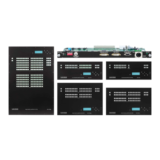
- Page 1 User’s Manual MX-FR9, MX-FR17, MX-FR33L MX-FR33R, MX-FR65R, MX-FR80R with MX-CPU2 and MX I/O Boards Hybrid Modular Multimedia Matrix...
- Page 2 MX-FR Series Modular Matrix Frames – User's Manual Important Safety Instructions Waste Electrical & Electronic Equipment Common Safety Symbols WEEE Class I apparatus construction. Symbol Description This marking shown on the product or its literature, This equipment must be used with a mains power system with a...
-
Page 3: Mx-Fr Series Modular Matrix Frames – User's Manual
MX-FR Series Modular Matrix Frames – User's Manual Symbol Legend Document Information About Printing The following symbols and markings are used in the document: All presented functions refer to the indicated products. The descriptions Lightware Visual Dngineering supports green technologies and have been made during testing these functions in accordance with the Dco-friend mentality. -
Page 4: Table Of Contents
MX-FR Series Modular Matrix Frames – User's Manual Aable of Contents 4.2.7. Preset Operations ................33 6.6. EDID Menu ..................74 1. INTRODUCTION ...................6 4.2.8. Output Lock ..................34 6.6.1. Sources and Destinations ............... 74 1.1. Description ...................6 4.3. The EDID Memory of a Matrix .............35 6.6.2. EDID Operations ................ - Page 5 MX-FR Series Modular Matrix Frames – User's Manual 7.3.20. Renaming an Output ..............86 7.8. Port Status Commands ..............94 10. TECHNOLOGIES ................126 7.3.21. Querying the Name of a Preset ............ 86 7.8.1. Input Port Status ................94 10.1. EDID Management ..............126 7.3.22. Querying the Name of an Input ............
-
Page 6: Introduction
MX-FR Series Modular Matrix Frames – User's Manual 1.1. Description 1.2. Box Contents Thank you for choosing Lightware matrix routers. The hybrid modular matrix routers are capable of routing DVI or HDMI signals in a scalable non-blocking crosspoint configuration, with up to 80 inputs and 80 outputs. -
Page 7: Features Of The Device
1. Introduction MX-FR Series Modular Matrix Frames – User's Manual 1.3. Features of the Device Non-blocking Crosspoint Matrix Architecture Advanced EDID Management Front Panel Control The router allows any input to be switched to any The user can emulate any DDID on the inputs Sources and destinations have their own button to output or more outputs simultaneously. - Page 8 1. Introduction MX-FR Series Modular Matrix Frames – User's Manual 1.4. Aypical Applications Local CATx cable CATx cable monitor LCD display DVI cable Optical cable with speakers Celling speakers HDMI cable Audio cable VGA cable Switcher Laptop...
-
Page 9: Installation
Switch it on and all the connected devices. AAAENAIONG! Fix the frame to the rack rail by applying all mounting To access the matrix and I/O port settings via Lightware Device holes. Choose properly sized screws for mounting. Ceep minimum Controller software see the Software Control –... -
Page 10: Board Installation And Handling
2. Installation MX-FR Series Modular Matrix Frames – User's Manual 2.3. Board Installation and Handling Step 3. Take the board by touching the metal plate only, to prevent Step 5. Gently push the board in until it stops, then press the plate at DSD-caused problems. -
Page 11: Psu Installation And Handling
2. Installation MX-FR Series Modular Matrix Frames – User's Manual 2.4. PSU Installation and Handling MX-FR33R Frame Step 3. Pull down the lever ( ), then pull out ( ) the PSU unit by grabbing the screw/lever. -
Page 12: Product Overview
3. Product Overview MX-FR Series Modular Matrix Frames – User's Manual 3.1. Hybrid Modular Matrix Concept 3.4. MX-CPU2 Processor Board Lightware’s hybrid modular matrix routers allow building custom I/O The CPU board is necessary for the router frame to work. This board is sizes which meets the user’s requirements. -
Page 13: Mx-Cpu2 Board Features
3. Product Overview MX-FR Series Modular Matrix Frames – User's Manual 3.5. Input Boards MX-FR65R Limitations The MX-FR65R matrix frame is physically identical to the MX-FR80R. Several input interface boards are available. Dach model has different capabilities and functions. Below table shows a summary of the main features. -
Page 14: Output Boards
3. Product Overview MX-FR Series Modular Matrix Frames – User's Manual 3.6. Output Boards Several output interface boards are available. Dach model has different capabilities and functions. The table below shows a summary of the main features. -
Page 15: Mx-Fr80R And Mx-Fr65R
3. Product Overview MX-FR Series Modular Matrix Frames – User's Manual 3.7. MX-FR80R and MX-FR65R Front View Menu display Displays status information and menu operation. Menu navigation Up, down, left, right, escape, and enter buttons for menu navigation. - Page 16 3. Product Overview MX-FR Series Modular Matrix Frames – User's Manual Rear View Status LEDs LDD indicators for internal DC power voltages and alarm. 12 3 6 7 8 DIP settings Special settings can be made with these switches.
-
Page 17: Mx-Fr33R
3. Product Overview MX-FR Series Modular Matrix Frames – User's Manual 3.8. MX-FR33R Front View USB control USB connection for Lightware Device Controller software. Menu display Displays status information and menu operation. Menu navigation Arrows, escape, and enter buttons for menu navigation. - Page 18 3. Product Overview MX-FR Series Modular Matrix Frames – User's Manual Rear View Status LEDs LDD indicators for internal DC power voltages and alarm. 1 2 3 DIP settings Special settings can be made with these switches.
-
Page 19: Mx-Fr33L
3. Product Overview MX-FR Series Modular Matrix Frames – User's Manual 3.9. MX-FR33L Front View USB control USB connection for Lightware Device Controller software. Menu display Displays status information and menu operation. Menu navigation Arrows, escape, and enter buttons for menu navigation. - Page 20 3. Product Overview MX-FR Series Modular Matrix Frames – User's Manual Rear View Status LEDs LDD indicators for internal DC power voltages and alarm. 1 2 3 DIP settings Special settings can be made with these switches.
-
Page 21: Mx-Fr17
3. Product Overview MX-FR Series Modular Matrix Frames – User's Manual 3.10. MX-FR17 Rear View Front View 1 23 Status LEDs LDD indicators for internal DC Ethernet Locking RJ45 connector. USB control USB connection for Lightware Destination Destination buttons can be power voltages and alarm. -
Page 22: Mx-Fr9
3. Product Overview MX-FR Series Modular Matrix Frames – User's Manual 3.11. MX-FR9 12 3 Front View Status LEDs LDD indicators for internal DC Ethernet Locking RJ45 connector. USB control USB connection for Lightware Destination Destination buttons can be power voltages and alarm. -
Page 23: Electrical Connections
® Combicon series (3.5mm pitch), type: MC 1.5/2-ST-3.5. by CEA/CEDIA-863-B (ANSI) to aid correct connections. According to the standard Lightware uses red colored RCA connectors for the right channel of analog stereo audio signals and white colored RCA connectors for the left channel of analog stereo audio signals. -
Page 24: Rj45 Connectors And Twisted Pair Cables
LAN cable and swap to Dthernet fallback mode Lightware recommends the termination of TP cables on the basis of TIA/EIA T 568 A or TIA/EIA T 568 B automatically. In this case, the port works as an Dthernet switch, but TPS CAT TPS IN 2 standards. -
Page 25: Further Connectors
Ethernet Ports Alarm Output Lightware matrix routers can be remote controlled through Dthernet as well. The BNC output connector for SMPTD 269M alarm signaling. The router handles different error levels. Only the Dthernet port can be connected to a LAN hub, switch or router with a UTP patch... -
Page 26: Input Boards
3. Product Overview MX-FR Series Modular Matrix Frames – User's Manual 3.13. Input Boards MX-DVIDL-OPT-IB-SC MX-DVID-IB MX-DVI-HDCP-IB MX-DVI-4K-IB MX-DVII-HDCP-IB MX-DVI-TP-IB MX-DVI-TP-IB+ MXD-UMX-IB MX-DVI-OPT-IB-LC MX-HDMI-IB MX-DVI-OPT-IB-ST MX-HDMI-TP-IB MX-DVIDL-IB MX-DVIDL-OPT-IB-LC MXD-HDMI-TP-IB MX-DVIDL-OPT-IB-NT MX-HDMI-OPT-IB-LC... - Page 27 3. Product Overview MX-FR Series Modular Matrix Frames – User's Manual MX-HDMI-OPT-IB-NT MX-TPS2-IB-AP MX-HDMI-OPT-IB-SC MX-TPS2-IB-SP MX-3GSDI-IB MX-4TPS2-4HDMI-IB MX-TPS-IB MX-4TPS2-4HDMI-IB-A MX-TPS-IB-A MX-4TPS2-4HDMI-IB-S MX-TPS-IB-S MX-4TPS2-4HDMI-IB-P MX-HDMI-3D-IB MX-4TPS2-4HDMI-IB-AP MX-HDMI-3D-IB-A MX-4TPS2-4HDMI-IB-SP MX-HDMI-3D-IB-S MX-TPS2-IB-P...
-
Page 28: Output Boards
3. Product Overview MX-FR Series Modular Matrix Frames – User's Manual 3.14. Output Boards MX-DVI-OPT-OB-R-ST MX-DVID-OB MX-DVIDL-OPT-OB-LC MX-DVI-4K-OB MX-DVIDL-OPT-OB-NT MX-DVI-TP-OB MX-DVI-DL-OB MX-DVI-TP-OB+ MX-DVI-HDCP-OB MX-DVI-OPT-OB-LC MX-HDMI-OB MX-DVI-OPT-OB-SC MX-HDMI-TP-OB MX-DVI-OPT-OB-ST MX-DVI-OPT-OB-R-LC MXD-HDMI-TP-OB MX-DVI-OPT-OB-R-NT MX-HDMI-OPT-OB-LC MX-DVI-OPT-OB-R-SC MX-HDMI-OPT-OB-NT... - Page 29 3. Product Overview MX-FR Series Modular Matrix Frames – User's Manual MX-TPS2-OB-P MX-HDMI-OPT-OB-SC MX-TPS2-OB-AP MX-HDMI-3D-OB MX-TPS2-OB-SP MX-HDMI-3D-OB-A MX-AUDIO-OB-A MX-HDMI-3D-OB-S MX-4TPS2-4HDMI-OB MX-HDMI-OPT-OB-R-LC MX-4TPS2-4HDMI-OB-A MX-HDMI-OPT-OB-R-NT MX-4TPS2-4HDMI-OB-S MX-HDMI-OPT-OB-R-SC MX-4TPS2-4HDMI-OB-P MX-TPS-OB MX-4TPS2-4HDMI-OB-AP MX-TPS-OB-A MX-4TPS2-4HDMI-OB-SP MX-TPS-OB-S...
-
Page 30: Operation
4. Operation MX-FR Series Modular Matrix Frames – User's Manual 4.1. Powering on Redundant PSU Aypes INFO: The type of the PSU in the MX-FR33R frame is MX-PSU-350 Connect the power cords to the power supply units’ IEC standard while the PSU in the MX-FR65R and MX-FR80R frames is FNP850- power input connector. -
Page 31: Basic Control Panel Operations
4. Operation MX-FR Series Modular Matrix Frames – User's Manual 4.2. Basic Control Panel Operations 4.2.3. Source and Destination Buttons For viewing input connections, press and release a source button. Now the selected source button and all destination buttons will light Normal I/O ports have dedicated buttons on the front panel. -
Page 32: Switching
4. Operation MX-FR Series Modular Matrix Frames – User's Manual 4.2.5. Switching Disconnecting or Muting in Aake Mode Creating a Connection in Autotake Mode Step 1. Press and release the selected source button. Step 1. Press and release the desired destination button. -
Page 33: Switching Operations Flowchart
4. Operation MX-FR Series Modular Matrix Frames – User's Manual 4.2.6. Switching Operations Flowchart 4.2.7. Preset Operations Loading a Preset in Aake Mode Step 1. Press and release the Load Preset button. DDFINITION: A preset stores a configuration regarding all input Aake Mode connections and mute state for all outputs. -
Page 34: Output Lock
Lock button illuminates regarding the lock state of the current output. Using Lightware routers it is possible to lock a destination’s state. This Step 3. Press and release the Take button. feature prevents an accidental switching to the locked destination in Viewing all locked outputs is not possible is Autotake mode, as pressing the case of an important signal. -
Page 35: The Edid Memory Of A Matrix
4. Operation MX-FR Series Modular Matrix Frames – User's Manual 4.3. The EDID Memory of a Matrix Locking an Output in Autotake Mode DVI EDIDs does not support audio. The Universal DVI DDID indicates support for many PC (VDSA) resolutions. -
Page 36: Audio Settings
4. Operation MX-FR Series Modular Matrix Frames – User's Manual 4.4.2. Audio Settings (B) HDMI Audio Pass-through (C) Embed From Aux Audio The HDMI video (with embedded audio) goes towards the HDMI It means the original embedded audio is swapped for the auxiliary... -
Page 37: Tps Link Modes
4. Operation MX-FR Series Modular Matrix Frames – User's Manual 4.5. APS Link Modes (D) De-embed to Aux Audio (E) HDMI Pass-through and De-embed to Aux Audio The embedded audio of the HDMI video is eliminated and the video... -
Page 38: About The Ethernet (Tps Boards)
4. Operation MX-FR Series Modular Matrix Frames – User's Manual 4.6. About the Ethernet (TPS Boards) 4.6.2. Avoid Causing an Ethernet Loop If the TPS board is connected to LAN and the Dthernet channel is enabled on a TPS port, the device which is connected* to this port is... -
Page 39: Lcd Control Panel Operation
4. Operation MX-FR Series Modular Matrix Frames – User's Manual 4.7. LCD Control Panel Operation 4.7.2. Normal Mode Menu Structure Up ▲ and down ▼ buttons select 4.7.1. Basic Concept Normal mode ~IP settings >> between menu items. More items... - Page 40 4. Operation MX-FR Series Modular Matrix Frames – User's Manual IP Address Submenu 4.7.2.3. Protocol Settings Menu Use the left ◄ and right ► buttons to Input 9 settings Navigate to this item with the up ▲...
- Page 41 4. Operation MX-FR Series Modular Matrix Frames – User's Manual The Add-on source setting is accessible only with MXD-UMX-IB. The Input Port Settings Submenu (DVIDL type) Input Port Settings Submenu (TPS type) analog stereo and S/PDIF conversion...
- Page 42 4. Operation MX-FR Series Modular Matrix Frames – User's Manual The pattern can be solid green, blue, black, white or black and white ramp Input Port Settings Submenu (HDMI-3D type) The Analog Audio Input settings are available in the case of an MX-TPS- and chessboard or color bar.
- Page 43 4. Operation MX-FR Series Modular Matrix Frames – User's Manual Output Port Settings Submenu (DVI-D type) The Colorrange can be set to compress, expand or Auto. Use the left ◄ Output Port Settings Submenu (TPS type) and right ►...
- Page 44 4. Operation MX-FR Series Modular Matrix Frames – User's Manual The Audio mode settings are available in the case of MX-TPS-OB-A and Output Port Settings Submenu (HDMI-3D type) The Audio mode settings are available in the case of MX-HDMI-3D-OB-A MX-TPS-OB-S boards.
- Page 45 4. Operation MX-FR Series Modular Matrix Frames – User's Manual Output Port Settings Submenu (HDMI-OPT-R type) The laser on each output port can be enabled or disabled. Disabling 4.7.2.8. Card Information Menu unused laser outputs can lengthen...
- Page 46 4. Operation MX-FR Series Modular Matrix Frames – User's Manual IP Reset Submenu Protocol Reset Submenu 4.7.2.12. View Log Menu This operation reloads the factory This operation sets the Lightware Navigate to this menu in the main ~Protocol reset >>...
-
Page 47: Lcd Menu Pop-Up Messages
4. Operation MX-FR Series Modular Matrix Frames – User's Manual Use the up ▲ button to the select the Test input port and the down ▼ The configuration file name includes the date and time when the button to select the Preview output port. -
Page 48: Edid Mode
4. Operation MX-FR Series Modular Matrix Frames – User's Manual 4.7.4. EDID Mode Switch EDID Menu Signal on Aest Input The emulated DDIDs can be changed This screen shows actual To enter or to exit from this mode press and release the EDID button. -
Page 49: Remote Operation
4. Operation MX-FR Series Modular Matrix Frames – User's Manual 4.8. Remote Operation 4.8.3. IP Settings User Interface Comparison The built-in website and Lightware Device Controller have similar The Ethernet port can be configured on the front panel LCD menu or Lightware matrix routers can be controlled through various interfaces capabilities. -
Page 50: Control Protocols
Be aware that different control interfaces can be set WARNING The MX-CPU2 can detect and log many system events. Dvery log entry to use different protocols. D.g. Lightware protocol is set on Dthernet MATTDR gets a time stamp based on the CPU real time clock. These events are interface while Protocol #2 is set on the Serial interface at the same categorized by levels. -
Page 51: Software Control - The Built-In Web
Other TCP/IP connections are prohibited. matrix via a web browser. The range of the controlling features are not so wide as in the case of Lightware Device Controller, but numerous information is displayed and many settings are available. -
Page 52: Software Control - Lightware Device Controller Software
Windows PC or macOS. Ahe application can be downloaded from only this instance www.lightware.eu. Ahe Windows and the Mac versions have the same look and The common way to start the software is double-click on the LDC... -
Page 53: Connecting To A Device (Device Discovery Window)
▪ Favorite devices: You can add any Lightware device that is connected via Dthernet and no need to browse all the available devices. All devices: The Lightware devices are listed which are available in the network. ▪ Further Aools The Tools menu contains the following options: ▪... -
Page 54: Crosspoint Menu
6. Software Control – Lightware Device Controller Software MX-FR Series Modular Matrix Frames – User's Manual 6.4. Crosspoint Menu Main Menu The available menu items are displayed. The active one is highlighted with a dark grey background color. - Page 55 6. Software Control – Lightware Device Controller Software MX-FR Series Modular Matrix Frames – User's Manual 6.4.1.1. Ahe Legend Window 6.4.1.2. Crosspoint Operations MX-FR frames can be equipped with different type of boards. The colored bars below/next to the input/ Switching output ports display the type of the board in each slot.
-
Page 56: Tile View
6. Software Control – Lightware Device Controller Software MX-FR Series Modular Matrix Frames – User's Manual 6.4.2. Aile View Input Ports Dach tile represents an input port. If window size The tile view is to display the input and output ports by tiles. Dach tile means an input or output port and additionally shows the most important port and does not allow to display all the ports, pages can be signal information. - Page 57 6. Software Control – Lightware Device Controller Software MX-FR Series Modular Matrix Frames – User's Manual 6.4.2.1. Port Ailes 6.4.2.2. Display Modes The colors of the port tiles and the displayed icons represent different states and information: View Mode...
-
Page 58: Port Properties And Settings
6. Software Control – Lightware Device Controller Software MX-FR Series Modular Matrix Frames – User's Manual 6.5. Port Properties and Settings There are two equalization modes: automatic and manual. Automatic mode usually provides perfect transmission but at longer distances and higher resolutions, manual equalization may be necessary. By Parameters Press the desired port button on the port bar on the right. -
Page 59: Diagnostic Tools
Frame detector button. RS-232 Aerminal Lightware’s Frame Detector function works like a signal analyzer and makes possible to determine the exact The RS-232 commands can be sent via this terminal or protocol commands (for protocol commands see the video format that is present on the port, thus helps to identify many problems. -
Page 60: Input Port Properties
6. Software Control – Lightware Device Controller Software MX-FR Series Modular Matrix Frames – User's Manual 6.5.2.2. APS Cable Diagnostics 6.5.2.3. Aest Pattern Generator The cable diagnostics is a useful tool to determine any Supported Boards: available for the most of the boards. - Page 61 6. Software Control – Lightware Device Controller Software MX-FR Series Modular Matrix Frames – User's Manual 6.5.3.2. DVI-OPA Aype Input Ports Cable Equalization Supported Boards: Automatic mode usually provides perfect transmission but at longer distances and higher resolutions, manual equalization may be necessary.
- Page 62 6. Software Control – Lightware Device Controller Software MX-FR Series Modular Matrix Frames – User's Manual 6.5.3.5. HDMI Type Input Ports Cable Equalization Supported Boards: The Auto setting means that equalization will be adaptive (depending on the cable length). By default, automatic equalization is enabled.
- Page 63 6. Software Control – Lightware Device Controller Software MX-FR Series Modular Matrix Frames – User's Manual 6.5.3.6. HDMI-3D Type Input Port Supported Boards: ▪ MX-4TPS2-4HDMI-IB, -A, -S, -P, -AP, -SP (only the four HDMI ports of the boards) MX-HDMI-3D-IB, -A, -S ▪...
- Page 64 6. Software Control – Lightware Device Controller Software MX-FR Series Modular Matrix Frames – User's Manual 6.5.3.7. DVI-I Aype Input Port Supported Boards: ▪ MX-DVII-HDCP-IB MXD-UMX-IB ▪ Video Source The signal type of the connected source can be selected in the drop down list: Analog RGB, Analog YUV, Analog Auto, Digital, or Auto source.
- Page 65 Remote Device (valid only for certain extenders) “C” HDMI deembedded HDMI embedded TPS boards can display the name of the remote Lightware device; it is displayed in the TPS Link section. HDMI Analog from input port to crosspoint S/PDIF HDMI...
- Page 66 6. Software Control – Lightware Device Controller Software MX-FR Series Modular Matrix Frames – User's Manual Numerous settings and parameters are available on the tabs, like: ▪ Changing TCP/IP settings, opening a new LDC window showing the remote device.
- Page 67 6. Software Control – Lightware Device Controller Software MX-FR Series Modular Matrix Frames – User's Manual 6.5.3.9. 3G-SDI Aype Input Port Output Mode Supported Board: The output signal type can be selected (DVI or HDMI mode) which is sent towards the matrix crosspoint.
-
Page 68: Output Port Properties
The signal is reclocked on the output. The reclocking performance can be adjusted if the signal drops on the Parameters display device. The default setting gives good result in most cases. The factory default settings give good result in most cases. Please contact Lightware Support Dual-Link Mode (support@lightware.com) for further information if encountering problems with output signals. - Page 69 6. Software Control – Lightware Device Controller Software MX-FR Series Modular Matrix Frames – User's Manual 6.5.4.3. HDMI Type Output Port 6.5.4.4. HDMI-3D Type Output Port Supported Boards: Supported Boards: ▪ MX-HDMI-OB, MX-DVI-HDCP-OB ▪ MX-HDMI-3D-OB, -A, -S; MX-4TPS2-4HDMI-OB, -A, -S, -P, -AP, -SP (only the four HDMI ports of the board)
- Page 70 6. Software Control – Lightware Device Controller Software MX-FR Series Modular Matrix Frames – User's Manual 6.5.4.5. DVI-OPA Aype Output Port 6.5.4.6. HDMI-OPT Type Output Port Supported Boards: Supported board: ▪ MX-DVI-OPT-OB-LC, -SC, -ST ▪ MX-HDMI-OPT-OB-LC, -NT, -SC MX-DVIDL-OPT-OB-LC, -NT ▪...
- Page 71 6. Software Control – Lightware Device Controller Software MX-FR Series Modular Matrix Frames – User's Manual 6.5.4.7. HDMI-OPT-R Type Output Port Signal Properties Supported Boards: ▪ The signal mode can be set to DVI, HDMI or No change mode.
- Page 72 The diagrams of TPS2 ports can be seen on the figures which are almost the same as of TPS boards can display the name of the remote Lightware device which is displayed in the TPS Link section. TPS ports. The only difference is the remote power feature (12V / 48V).
-
Page 73: Presets
MX-FR Series Modular Matrix Frames – User's Manual 6.5.5. Presets Preset operations can be done in Crosspoint submenu on the Preset tab. Dach Lightware matrix routers has 32 preset memories that can be loaded and saved at any time. INFO: A preset setting stores a full configuration of all outputs, so preset loading has an effect on every output, except the locked ones. -
Page 74: Edid Menu
6. Software Control – Lightware Device Controller Software MX-FR Series Modular Matrix Frames – User's Manual 6.6. EDID Menu The Advanced DDID Management is available in the DDID menu. There are two panels: left one contains Source DDIDs, right one contains Destination places where the DDIDs can be emulated or copied. -
Page 75: Edid Operations
6. Software Control – Lightware Device Controller Software MX-FR Series Modular Matrix Frames – User's Manual 6.6.2. EDID Operations 6.6.3. EDID Summary Window Select an DDID from Source panel and press Info button to display DDID summary. Changing the Emulated EDID Step 1. -
Page 76: Editing An Edid
EDID file, or uploaded to the User memory. For more details about EDID Editor details about DDID Dditor please visit our website (www.lightware.com) and download DDID Dditor user's please visit our website (www.lightware.com) and download DDID Dditor user's manual. -
Page 77: Settings Menu
6. Software Control – Lightware Device Controller Software MX-FR Series Modular Matrix Frames – User's Manual 6.7. Settings Menu 6.7.1. Configuration Tab Communication settings are available on this tab. INFO: Load default button restores the default network settings in the device. -
Page 78: Device Information
6. Software Control – Lightware Device Controller Software MX-FR Series Modular Matrix Frames – User's Manual 6.7.2. Device Information Basic information about the matrix frame and about the installed boards are listed on this tab: CPU board with controllers ▪... -
Page 79: Log
Apple Safari is not supported. LDC is able to collect information from the device and save it to a report file. This information package can be sent to Lightware support team when a problem may arise with the device: Step 1. Press the red button: Generate report file. -
Page 80: User Preferences
6. Software Control – Lightware Device Controller Software MX-FR Series Modular Matrix Frames – User's Manual 6.7.5. User Preferences The tab shows some settings in connection with the LDC displaying/ working mode. These settings are saved by the LDC and applied next... -
Page 81: Programmer's Reference
MX-FR Series Modular Matrix Frames – User's Manual 7.1. Protocol Description The protocol description hereinafter stands for Lightware protocol. The commands can be sent to the device in RAW format via the TCP/IP port no. 10001. The matrix routers accept commands surrounded by curly brackets - { } - and responds data surrounded by round brackets - ( ) - only if a command was successfully executed. -
Page 82: Storage Memories
7. Programmer’s Reference MX-FR Series Modular Matrix Frames – User's Manual 7.2. Storage Memories 7.3. Switching and Control Commands The matrix stores many configuration settings and parameters and uses different memories. In some cases, 7.3.1. Aest Input and Preview Output it is important to know which setting is stored in which memory. -
Page 83: Switching An Input To An Output
7. Programmer’s Reference MX-FR Series Modular Matrix Frames – User's Manual 7.3.3. Switching an Input to an Output 7.3.6. Batch Switch Outputs Description: Switch input <in> to output <out>. Description: The router is capable of switching multiple outputs exactly at the same time. To do this, the normal switch commands have to be used. -
Page 84: Displaying The Current Connection States Of The Outputs
7. Programmer’s Reference MX-FR Series Modular Matrix Frames – User's Manual 7.3.7. Displaying the Current Connection States of the Outputs 7.3.8. Listing the Mute/Unmute States of All Outputs Description: Viewing all outputs’ connection results in different response length, because it depends on the AAAENAIONG! The response length depends on the frame size. -
Page 85: Disconnecting An Output
7. Programmer’s Reference MX-FR Series Modular Matrix Frames – User's Manual 7.3.11. Disconnecting an Output 7.3.15. Saving a Preset Description: Switch an output to a virtual unconnected input. No signal on the output. Description: Save current crosspoint configuration (output states) to preset <id>. -
Page 86: Renaming A Preset
7. Programmer’s Reference MX-FR Series Modular Matrix Frames – User's Manual 7.3.18. Renaming a Preset 7.3.24. Reloading the Default Preset Names Format Example AAAENAIONG! The <id> field is not relevant here, only has to be a valid one. The command will affect ALL presets disregarding the actual number that was in the command. -
Page 87: Communication Setup Commands
7. Programmer’s Reference MX-FR Series Modular Matrix Frames – User's Manual 7.4. Communication Setup Commands 7.4.3. Setting a Dynamic IP Address (DHCP) Description: After sending this command the router will inquire IP address with DHCP. 7.4.1. Querying the IP Settings... -
Page 88: Querying The Control Protocol
Be aware that different control interfaces can be set to use different protocols. D.g. the Explanation: The matrix will send an immediate message on all control interfaces when a ‘matter’, ‘error’ or Dthernet interface can use the Lightware protocol while the Serial interface uses Protocol#2 at the same ‘fatal’ level error occurs. -
Page 89: Querying The Serial Number
7. Programmer’s Reference MX-FR Series Modular Matrix Frames – User's Manual 7.5.2. Querying the Serial Number 7.5.6. Querying the Number of the Allowed I/O Slots Description: The device responds its 8-digit serial number. Description: Check the allowed number of I/O boards. -
Page 90: Querying The Firmware Of All Controllers
7. Programmer’s Reference MX-FR Series Modular Matrix Frames – User's Manual 7.5.8. Querying the Firmware of All Controllers’ 7.5.11. Querying the Error List Description: Shows the firmware versions of all installed controllers. The number of responses depends on Description: Shows the basic error list since last boot up. -
Page 91: Querying The Cpu Time
7. Programmer’s Reference MX-FR Series Modular Matrix Frames – User's Manual 7.6.2. Querying the CPU Time 7.6.5. Reloading the Factory Default Values and Settings Description: This command allows reading the CPU time. Description: Factory default settings can be reloaded for different functions separately. Multiple functions can be entered. -
Page 92: Edid Router Commands
7. Programmer’s Reference MX-FR Series Modular Matrix Frames – User's Manual 7.7. EDID Router Commands 7.7.3. Saving an EDID to the User Memory Description: Learn DDID from <loc2> to <loc1>. The EDID router manipulates the EDID memory, which has memory locations that are assigned to specific input or output ports. -
Page 93: Querying The Emulated Edids On All Inputs
7. Programmer’s Reference MX-FR Series Modular Matrix Frames – User's Manual 7.7.5. Querying the Emulated EDIDs on All Inputs The <EDID_HEADER> consists of 3 fields separated by spaces: Description: Shows the currently emulated DDIDs for each input. The response length depends on the frame <loc>... -
Page 94: Uploading The Edid Content
7. Programmer’s Reference MX-FR Series Modular Matrix Frames – User's Manual 7.7.9. Uploading the EDID Content Explanation: The first input board is an HDMI board. Input 1 and 2 have a connected source but no signal. Inputs 3-5 have DVI signals and inputs 6-8 have HDMI signals. The second input board is a DVI board. Input Description: DDID hex bytes can be written directly to the user programmable memory locations. -
Page 95: Output Port Status
7. Programmer’s Reference MX-FR Series Modular Matrix Frames – User's Manual 7.8.2. Output Port Status 7.8.3. All Port Status Description: Shows the actual status of the output ports. The response length changes regarding the frame Description: Shows the actual status of all input and output ports. - Page 96 7. Programmer’s Reference MX-FR Series Modular Matrix Frames – User's Manual Legend 7.9.1.2. Remote Power Settings (PoE) Supported Boards: Identifier Parameter Description Parameter Values Read/write Parameters ▪ MX-TPS2-IB-P, -AP, -SP MX-4TPS2-4HDMI-IB-P, -AP, -SP ▪ <in>/<out> Input or output port number Port number in 1- or 2-digit ASCII format (01, 3, 04, etc.)
-
Page 97: Hdmi Input Port
7. Programmer’s Reference MX-FR Series Modular Matrix Frames – User's Manual 7.9.2. HDMI Input Port <video> block INFO: This block is present only if a valid video signal is present on the selected port. 7.9.2.1. Port Parameters and Settings... - Page 98 7. Programmer’s Reference MX-FR Series Modular Matrix Frames – User's Manual <audio> block Example: A1C010000 INFO: This block is present only if a valid video signal is present on the selected port. PCM audio is present at 48 kHz. The codec is not specified, two audio channels are defined.
-
Page 99: Hdmi-3D Input Port
D002402C0501004008630C)CrLf 0 = The clock signal is unstable on the TMDS clock line For more information about the measured values, please contact Lightware Support. <d> TMDS clock line stability 1 = The clock signal is stable on the TMDS clock 7.9.3. HDMI-3D Input Port... -
Page 100: Resolutions
7. Programmer’s Reference MX-FR Series Modular Matrix Frames – User's Manual Legend <audio> block <INFO> block INFO: This block is present only if a valid video signal is present on the selected port. The signal info block contains general information about the signal. The first character of this block is S. - Page 101 7. Programmer’s Reference MX-FR Series Modular Matrix Frames – User's Manual Example: A1C010000 <adv_info> block PCM audio is present at 48 kHz. The codec is not specified, two audio channels are defined. INFO: This block is present only if a valid video signal is present on the selected port.
-
Page 102: Hdmi Output Port
<Timing_codes>)CrLf D002402C0501004008630C)CrLf <in_set> block For more information about the measured values, please contact Lightware Support. You are able to verify the actual settings on the selected input ports with this block as this block is always 7.9.4. HDMI Output Port present. The first character is P, the second is X. - Page 103 7. Programmer’s Reference MX-FR Series Modular Matrix Frames – User's Manual Setting the Parameters Identifier Parameter Description Parameter Values Explanation: The signal type is set to DVI, the other parameters have not been changed. Use the 'x' character <Width>...
- Page 104 7. Programmer’s Reference MX-FR Series Modular Matrix Frames – User's Manual <out_set> block <sink> block The output settings block contains information about the actual settings of the selected port. The first INFO: This block is present only if a sink device is connected to the selected port.
-
Page 105: Hdmi-3D Output Port
3 = HDMI signal is transmitted (deep color, 36 bit) <Timing_codes>)CrLf D002402C0501004008630C)CrLf 0 = No valid signal is routed to the port For more information about the measured values, please contact Lightware Support. <c> Signal validity 1 = Valid video signal is present 7.9.5. HDMI-3D Output Port... - Page 106 7. Programmer’s Reference MX-FR Series Modular Matrix Frames – User's Manual <audio> block Example: A1C010000 INFO: This block is present only if a valid video signal is present on the selected port. PCM audio is present at 48 kHz. The codec is not specified, two audio channels are defined.
- Page 107 7. Programmer’s Reference MX-FR Series Modular Matrix Frames – User's Manual <adv_info> block <ext_info> block INFO: This block is present only if a valid video signal is present on the selected port. Additional information about the 3D-capable ports is displayed in this block. The first character of this block is D.
- Page 108 D002402C0501004008630C)CrLf This block provides some general information about the attached sink device based on the DDID and the For more information about the measured values, please contact Lightware Support. HDCP cypher engine. The first character of this block is M.
-
Page 109: Dvi-I Input Port
7. Programmer’s Reference MX-FR Series Modular Matrix Frames – User's Manual 7.9.6. DVI-I Input Port Legend (the first six common parameters) 7.9.6.1. Port Parameters and Settings Identifier Parameter Description Parameter Values R = analog RGB Supported Boards: Y = analog YUV ▪... - Page 110 Description: The system continuously measures the parameters of the signals. The answer consists of 12 parameters which could be useful for advanced debugging processes. Querying the Parameters Format Example Command {:GETTIMINGS#<in>@<S/C/A>I=?} → {:GDTTIMINGS#9@SI=?} Response (GETTIMINGS#<in>@<S/C/A>I= ← (GDTTIMINGS#9@SI=2200;1920;89;44;147; <Timing_codes>;)CrLf 1125;1080;4;5;36;148484;24;)CrLf For more information about the measured values, please contact Lightware Support.
-
Page 111: Umx Input Port
7. Programmer’s Reference MX-FR Series Modular Matrix Frames – User's Manual 7.9.7. UMX Input Port 7.9.8. Analog Audio I/O Port 7.9.7.1. Port Parameters and Settings 7.9.8.1. Output Port Parameters The port parameters and settings are the same as in the case of DVI-I input port, see the... -
Page 112: Dvi-Dl Output Port
7. Programmer’s Reference MX-FR Series Modular Matrix Frames – User's Manual 7.9.9. DVI-DL Output Port 7.9.8.2. Input Port Parameters Supported Boards: Supported Boards: ▪ MX-TPS-IB-A, -AP; MX-TPS-OB-A, -AP MX-DVIDL-OB ▪ MX-4TPS2-4HDMI-IB-A; MX-4TPS2-4HDMI-IB-AP ▪ Description: Query or set the dual-link DVI output port parameters. -
Page 113: Dvi-Opt Output Port
7. Programmer’s Reference MX-FR Series Modular Matrix Frames – User's Manual 7.9.10. DVI-OPA Output Port 7.10. RICOD Related Commands Supported Boards: 7.10.1. Setting the RICOD MASAER Command MX-DVI-OPT-OB ▪ Description: Sets the RICOD command for the selected input port. -
Page 114: Querying The Set Ricod Master
7. Programmer’s Reference MX-FR Series Modular Matrix Frames – User's Manual 7.10.2. Querying the Set RICOD MASTER 7.11. RS-232 over Fiber Commands Description: Checks the status of the previously set RICOD command for the selected input port. AAAENAIONG! The control interfaces on the router (USB, IP, and RS232) have 57600 bit/sec maximum bandwidth, so heavy traffic should be avoided. -
Page 115: Sending Data In Binary Format
7. Programmer’s Reference MX-FR Series Modular Matrix Frames – User's Manual 7.11.2. Sending Data in Binary Format Binary (B#In=[received text as binary data, e.g. 736F6D657468696E67]) or Description: Sends the data from the matrix’s input or output port in binary format which is after the equal sign. -
Page 116: Over Tps Commands
7. Programmer’s Reference MX-FR Series Modular Matrix Frames – User's Manual 7.12. RS-232 over APS Commands 7.12.2. Sending Data in Binary Format Description: Sends the data from the matrix’s input or output port in binary format. INFO: The control interfaces on the router (USB, IP and RS232) have 57600 bit/sec maximum bandwidth, so heavy traffic should be avoided. -
Page 117: Querying The Serial Parameters
7. Programmer’s Reference MX-FR Series Modular Matrix Frames – User's Manual 7.13. Router Initiated Commands Binary (B#In=[received text as binary data, e.g. 736F6D657468696E67]) or 7.13.1. EDID Status Changed (B#On=[received text as binary data, eg. 736F6D657468696E67]) Description: This is sent after any command which changed the DDID table (DDID copy, DDID switch), or if a where n is the port number, I refers input, O stands for the output ports. -
Page 118: Commands - Quick Summary
7. Programmer’s Reference MX-FR Series Modular Matrix Frames – User's Manual 7.14. Commands – Quick Summary Communication Setup Commands See in Switching and Control Commands Operation Command Section See in Querying the IP Settings 7.4.1 {IP_CONFIG=?} Operation... - Page 119 7. Programmer’s Reference MX-FR Series Modular Matrix Frames – User's Manual EDID Router Commands RICOD Related Commands See in See in Operation Command Operation Command Section Section Changing the DDID on an Input Port 7.7.1 {<loc1>:<loc2>} Setting the RICOD MASTDR Command 7.10.1...
-
Page 120: Firmware Upgrade
MX-FR Series Modular Matrix Frames – User's Manual 8.1. Detailed Instructions of the Upgrade Use the Lightware Bootloader application to upgrade the router’s firmware(s). The matrix router can only be upgraded via LAN, so connect the matrix router to the local subnet or directly to the windows based computer with an Dthernet cross-link cable. - Page 121 8. Firmware Upgrade MX-FR Series Modular Matrix Frames – User's Manual Step 5. Finding the device. Step 6. Dstablishing the connection with the device. If the bootloader finds one or more routers their IP addresses, type and serial number are listed in the tree Double click on the IP address, then click Yes to establish view window.
-
Page 122: Forced Firmware Upgrade
AAAENAIONG! Use this option with caution as the manually typed IP address is not checked if it is a Lightware device or not. If the address belongs to an unknown network device then this may cause malfunction of the device. -
Page 123: Firmware Upgrade Of Tps(2) Ports
All MX-TPS and TPS2 I/O board’s port has a separate firmware. All of the 8 firmwares can be different version and they are stored on the board instead of the MX-CPU2. Therefore the firmware upgrade must be performed differently than MX-CPU2. The firmware upgrade can be performed with the Lightware Device Controller software. -
Page 124: Troubleshooting
9. Troubleshooting MX-FR Series Modular Matrix Frames – User's Manual Symptom Root cause Action Refer to General Problems CPU Link LED does The matrix is not Reset the matrix by LW2 command, or 7.6.1 not blink powered correctly unplug and reconnect the power cable. -
Page 125: How To Speed Up The Troubleshooting Process
In the case of Event Manager issue the event file and/or backup file from the Device Controller ▪ software. The more of the above information you can give us the better. Please send these information to the Lightware Support Team (support@lightware.com) to speed up the troubleshooting process. -
Page 126: Technologies
(dynamic EDID emulation). information about additional Detailed Timings, audio capabilities, For example, the Lightware device can be set up to emulate a sink speaker allocation and HDMI capabilities. It is important to know that device, which is connected to one of the outputs. -
Page 127: Hdcp Management
HDCP enabling/disabling function: the HDCP capability can be Protected MX-FR Matrix Non-HDCP disabled in the Lightware device. If HDCP is disabled, the connected content compliant sink Inter-pair skew source will detect that the sink is not HDCP capable, and turn off The layout is the same as in the previous case: non-HDCP compliant Skew between two differential wire pairs in a cable. -
Page 128: Dual-Link Dvi Signal
10. Technologies MX-FR Series Modular Matrix Frames – User's Manual 10.4. Dual-Link DVI signal Jitter In Dual-Link cables, 6 wire pairs carry the color information next to the TMDS clock signal. One color component is carried by two wire pairs, Signal instability in the time domain. -
Page 129: Command Transmission
10. Technologies MX-FR Series Modular Matrix Frames – User's Manual 10.5. RS-232 Command Aransmission Conference Room Application Control System Connection Lightware Hybrid Modular Matrix system provides bidirectional RS-232 signal transmission at remote endpoints. The feature is implemented... -
Page 130: The Ricod Technology
The intention of this feature is to prevent accidental or unwanted on the 1st and the 2nd video input and the 1st and the 3rd video output a Master, like the device on the right side. Lightware matrix routers switching when the remote device is installed near to the end-users. -
Page 131: Ricod-Capable Devices
▪ FP-UMX-TP-TX100, firmware version 1.1.0r and above. RICOD unlock command followed by an unlock operation on the front * The MX-FR series modular matrix frames with MX-CPU2 processor panel. boards (with firmware version 3.3.5r and above) support reduced RICOD capabilities: only MASTDR mode is available and only by... -
Page 132: Appendix
11. Appendix MX-FR Series Modular Matrix Frames – User's Manual 11.1. Specifications MX-FR17, MX-FR9 Power consumption ........max 160 W (546 BTU/hour) 11.1.1. General Rack mount ............... Yes, 4U high Compliance ..................CD Dimensions (mm) ..........W482 x D300 x H176 EMI/EMC .......... -
Page 133: Factory Default Settings
11. Appendix MX-FR Series Modular Matrix Frames – User's Manual 11.2. Factory Default Settings 11.3. Maximum Cable Lengths (TPS and TPS2 Boards) Control Front Panel buttons ................Yes Cable Lengths Network Settings Pixel Clock (Auto / Longreach TPS Mode) Serial port connector ..... -
Page 134: Factory Edid List
11. Appendix MX-FR Series Modular Matrix Frames – User's Manual 11.5. Factory EDID List Mem. Resolution Aype Mem. Resolution Aype Mem. Resolution Aype Mem. Resolution Aype 1280 x 720p @ 50.0 1364 x 768 @ 59.93 Hz... -
Page 135: Audio Cable Wiring Guide
11. Appendix MX-FR Series Modular Matrix Frames – User's Manual 11.6. Audio Cable Wiring Guide From Unbalanced Output to Balanced Input From Balanced Output to Balanced Input Inputs and outputs of audio devices are symmetric or asymmetric. -
Page 136: Firmware Release Notes
11. Appendix MX-FR Series Modular Matrix Frames – User's Manual 11.7. Firmware Release Notes ▪ HDCP is supported by crosspoint level (HDCP protected signal ▪ Dual protocol mode. (In Protocol#1 mode Protocol#2 commands is routed only to compatible output boards, so mixed cards are are also accepted.) - Page 137 ▪ MX-DVI-OPT-OB-RCLK menu filter settings is ▪ "Protocol reset" in Factory reset LCD menu - it restores Lightware 3.0.9 implemented on the 4-line LCD. protocol on RS232 and LAN. ▪ DVI-I board sent DVI signal in auto mode if a MX-DVI-HDCP-OB, Released: 2011-03-07 ▪...
- Page 138 ▪ I2C speed has been reduced to 100 kHz during retrying the independently to each port by a new command. communication when NACC received from a SiI9134 or a SiI9135. 3.1.9 ▪ RS232 baudrate can be adjusted from Lightware protocol by ▪ MXD_HDMI_TP_IB support. {RS232BAUD=..} command. Released: 2011-10-10 ▪...
- Page 139 11. Appendix MX-FR Series Modular Matrix Frames – User's Manual ▪ MX-HDMI-OPT-IB didn't detect if the link was terminated. (The 3.2.5 3.2.8 bug appeared in 3.1.6) Released: 2012-02-20 Released: 2012-06-01 3.2.7 Bugfix Bugfix Released: 2012-05-30 ▪ New standard timing descriptors are applied. Standard resolution ▪...
- Page 140 ▪ MX-HDMI-3D-OB and MX-HDMI-3D-IB - several bugfixes related MXD-UMX-IB, MX-HDMI-3D-IB (and variants), MX-TPS-IB (and ▪ File uploading to SD card through Lightware protocol. (needed to test pattern modes, HDCP and infoframes. variants) cards and test input port. This is 15 times greater than for TPS fw upgrade) ▪...
- Page 141 ▪ Factory default test pattern changed from solid black to color now fixed by powering up the output ports not only when TMDS ▪ Lightware simple protocol mode (P_3) could hang if an unknown bar. Affected cards: MX-HDMI-3D-IB, MX-HDMI-3D-OB, MX-TPS- termination is present, but also after a hotplug event.
- Page 142 11. Appendix MX-FR Series Modular Matrix Frames – User's Manual ▪ Logging data extended, if VS100 holds I2C SCL line down. ▪ Some residual power from the output cards (from the connected New feature VS100_getHpdStatus function added (previously this register sink devices) could keep the CPU alive in MX-FR80 and MX-FR65 ▪...
-
Page 143: Mechanical Drawings
11. Appendix MX-FR Series Modular Matrix Frames – User's Manual 11.8. Mechanical Drawings 11.8.1. MX-FR80R and MX-FR65R Front view Rear view Right view Aop view MX-CPU2 DIP SETTING PREVIEW OUTPUT TEST INPUT RS-232 CPU LIVE CPU ALARM +12 V +5 V +3.3 V... -
Page 144: Mx-Fr33R
11. Appendix MX-FR Series Modular Matrix Frames – User's Manual 11.8.2. MX-FR33R 11.8.3. MX-FR33L Front view Rear view Front view Rear view MX-CPU2 DIP SETTING PREVIEW OUTPUT TEST INPUT RS-232 CPU LIVE MX-CPU2 DIP SETTING PREVIEW OUTPUT TEST INPUT... -
Page 145: Mx-Fr17 And Mx-Fr9
11. Appendix MX-FR Series Modular Matrix Frames – User's Manual 11.8.4. MX-FR17 and MX-FR9 11.9. ASCII Aable The most common used characters are highlighted with blue. Front view Rear view Char Char Char Char MX-CPU2 DIP SETTING PREVIEW OUTPUT... -
Page 146: Further Information
1.4. Product failures from six (6) months to the end of the warranty Laszlo 23-03-2017 (Auto); Programmer's Reference period will either be repaired or replaced at the discretion of Lightware. Zsedenyi chapter extended with port-specific If Lightware chooses to replace the product then the replacement will commands;...
Need help?
Do you have a question about the MX-FR Series and is the answer not in the manual?
Questions and answers