
Related Manuals for Lightware MX32x32HDMI-Pro


Summary of Contents for Lightware MX32x32HDMI-Pro
- Page 1 MX32x32HDMI-Pro MX16x16HDMI-Pro MX8x8HDMI-Pro MX32x32DVI-HDCP-Pro MX16x16DVI-HDCP-Pro MX8x8DVI-HDCP-Pro User's Manual...
-
Page 2: Safety Instructions
SAFETY INSTRUCTIONS Class I apparatus construction. This equipment must be used with a main power system with a protective earth connection. The third (earth) pin is a safety feature, do not bypass, or disable it. This equipment should be operated only from the power source indicated on the product. -
Page 3: Declaration Of Conformity
MX32x32DVI-HDCP-Pro and HDMI-Pro User’s Manual v1.0 DECLARATION OF CONFORMITY Lightware Kft. 1071 Budapest Peterdy str. 15 HUNGARY as manufacturer declares, that the products MX32x32HDMI-Pro MX16x16HDMI-Pro MX8x8HDMI-Pro MX32x32DVI-HDCP-Pro MX16x16DVI-HDCP-Pro MX8x8DVI-HDCP-Pro ( Video Matrix Switcher ) in accordance with the EMC Directive 2004/108/EC and the Low Voltage Directive 2006/95/EEC are in conformity with the following standards: EMI/EMC .... -
Page 4: Table Of Contents
Table of contents BOX CONTENTS..........................7 MODULAR ROUTER CONCEPT ....................8 2.1.......................... 8 SERIES 2.1.1. Front Panel view (all MX8x8 series) ................8 2.1.2. Rear view (MX8x8DVI-HDCP-Pro) ................9 2.1.3. Rear view (MX8x8HDMI-HDCP-Pro)................9 2.2. MX-DVI-FR16 ........................10 2.2.1. Rear view of MX-DVI-FR16 .................. - Page 5 Set color range conversion at a HDMI input port ............64 4.5.8. Set HDMI output port parameters ................64 4.5.9. Reset HDCP cache ....................66 4.5.10. Measure timing parameters..................66 SOFTWARE CONTROL –USING LIGHTWARE MATRIX CONTROLLER ........ 68 5.1....................68 STABLISHING THE CONNECTION 5.2........................69 ONTROL MENU 5.2.1.
- Page 6 5.7.2. Set HDMI parameters on output .................. 79 USING THE WEB INTERFACE ....................82 6.1. ’ ..................82 CCESSING THE ROUTER S WEB PAGE 6.2..................82 ANAGE CROSSPOINTS AND PRESETS 6.3. HDMI ........................83 SETTINGS 6.4. EDID R ...................... 85 OUTER OPERATION 6.4.1.
-
Page 7: Box Contents
MX32x32DVI-HDCP-Pro and HDMI-Pro User’s Manual v1.0 1. Box contents Routing switcher Rack mounting ears User's manual IEC power cable CD-ROM with control software RS-232 9-pole D-sub Male to Female cable UTP cross-link cable Page 7/ 109... -
Page 8: Modular Router Concept
2. Modular router concept MX8x8HDMI-Pro and MX8x8DVI-HDCP-Pro are fixed I/O size matrix switchers with eight inputs and eight outputs respectively. MX32x32 series and MX16x16 series Pro routers are modular matrix switchers that allow building custom I/O sizes that meet the user’s requirements. Different types of input and output cards give the maximum flexibility for rental and installation signal transmission. -
Page 9: Rear View (Mx8X8Dvi-Hdcp-Pro)
MX32x32DVI-HDCP-Pro and HDMI-Pro User’s Manual v1.0 2.1.2. Rear view (MX8x8DVI-HDCP-Pro) AC Power RS-232 DVI-D Inputs Card activity connector port LEDs Fuse Ethernet port DVI-D Outputs 2.1.3. Rear view (MX8x8HDMI-HDCP-Pro) AC Power RS-232 Card activity connector port HDMI Inputs Input status LEDs LEDs Fuse Ethernet... -
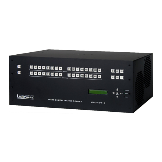
Page 10: Mx-Dvi-Fr16
2.2. MX-DVI-FR16 The MX-DVI-FR16 modular frame allows building custom matrices with up to 16 inputs and 16 outputs. The card in the uppermost slot must be a CPU card that is responsible for controlling the matrix. The two input and two output slots accept any kind of input and output card which are described in section 2.5 and section 2.6. -
Page 11: Cpu-Card
MX32x32DVI-HDCP-Pro and HDMI-Pro User’s Manual v1.0 2.4. CPU-CARD Reset GPIO contact DC voltage RS-232/422 Ethernet CPU LIVE button switch closure indicators port port In order for the MX-DVI-FR16(R) and MX-DVI-FR32R frames to work, a CPU- CARD is needed. This card is responsible for controlling the matrix and storing all the settings. -
Page 12: Input Cards
2.5. Input Cards 2.5.1. MX-DVI-HDCP-IB DVI connectors Card active LED This 8-channel DVI-D (digital only) input card supports single link DVI signals up to 165MHz pixel clock and HDMI 1.3 signals including deep color modes and audio signals. The built-in cable equalization enables the use of long cables as specified on page 25. -
Page 13: Mx-Hdmi-Ib
MX32x32DVI-HDCP-Pro and HDMI-Pro User’s Manual v1.0 2.5.2. MX-HDMI-IB Status LEDs HDMI connectors Card active LED This 8-channel HDMI input card has exactly the same capabilities as the MX-DVI-HDCP-IB described above in section 2.5.1. It is built with 19-pole type A HDMI connectors and each input has four status LEDs to help the installation and debugging process. -
Page 14: Mx-Hdmi-Tp-Ib
This card is compatible with the following Lightware products: DVI-HDCP-TP-TX100 HDMI-HDCP-TP-TX100 MX-HDMI-TP-OB (see 2.6.3.) DVI-TP-TX200 (DVI signals only, HDCP is not supported) MX-DVI-TP-OB card (DVI signals only, HDCP is not supported) For further details on these devices, please visit the http://www.lightware.eu webpage. Page 14 / 109... -
Page 15: Mx-Opt-Hdmi-Ib
(can be ordered with with NT, LC, ST or SC connectors) This 8-channel optical input card is fully compatible with the HDMI 1.3 and HDCP 1.3 standard. This card uses Lightware’s Single Fiber Technology, which eliminates the need for additional copper cables. Only one multimode fiber cable is used per one DVI signal. -
Page 16: Output Cards
2.6. Output Cards 2.6.1. MX-DVI-HDCP-OB DVI connectors Card active LED 8-channel DVI-D (digital only) output card. It is compatible with HDMI1.3 and HDCP standards and allows making specific conversions independently on each output port. These conversions can be done automatically based on the EDID of the display or can be manipulated manually. -
Page 17: Mx-Hdmi-Ob
MX32x32DVI-HDCP-Pro and HDMI-Pro User’s Manual v1.0 2.6.2. MX-HDMI-OB HDMI outputs S/PDIF outputs Card active LED 8-channel HDMI 1.3 compatible output card. Each output port has an RCA connector on which S/PDIF audio is sent, however the audio signal can be transmitted on the HDMI ports at the same time. -
Page 18: Mx-Hdmi-Tp-Ob
This card is compatible with the following Lightware products: DVI-HDCP-TP-RX100 HDMI-HDCP-TP-RX100 MX-HDMI-TP-IB (see 2.5.3) DVI-TP-RX100 (DVI signals only, HDCP is not supported) MX-DVI-TP-IB card (DVI signals only, HDCP is not supported) For further details on these devices, please visit the http://www.lightware.eu webpage. Page 18 / 109... -
Page 19: Mx-Opt-Hdmi-Ob
(Can be ordered with NT, LC, ST or SC connectors) This 8-channel optical output card is fully compatible with the HDMI 1.3 and HDCP 1.3 standards. This card uses Lightware’s Single Fiber Technology, which eliminates the need for additional copper cables. -
Page 20: General Features
HDCP compliant – All DVI-HDCP and HDMI routers comply with HDCP1.2 standard. Lightware is a legal HDCP adopter. The included advanced HDCP management eliminates the need for reauthentication upon switching. 50 meter input cable compensation – Using 22AWG high quality DVI or HDMI... - Page 21 MX32x32DVI-HDCP-Pro and HDMI-Pro User’s Manual v1.0 type, scan rate, HDCP encryption and so on. (on specific cards) Color space and color range conversion – Video signals can be converted between RGB, YUV 4:4:4 and YUV 4:2:2 signals in all directions. Converting between limited and full range is also possible.
-
Page 22: Electrical Connections
TMDS Clock Shield DDC Data GND (for +5V) TMDS Clock+ Hot Plug Detect TMDS Clock- DVI connector Single Link pin assignment MX32x32HDMI-Pro, MX16x16HDMI-Pro, and MX8x8HDMI-Pro provide 19-pole type A HDMI connectors for input connections. Signal Signal TMDS Data2+ TMDS Data2- TMDS Data1+... - Page 23 MX32x32DVI-HDCP-Pro and HDMI-Pro User’s Manual v1.0 MX-HDMI-TP-IB and MX-HDMI-TP-OB cards use two RJ45 connectors per each input. Video (left connector) DDC (right connector) Signal Signal TMDS Data0+ TMDS Data0- Hot Plug Detect (out) TMDS Clock+ RS232 TX (out) TMDS Data1+ RS232 RX TMDS Data1- DDC SCL...
-
Page 24: Br-N Optional Neutrik Breakout Box
Fiber A SC connector 2.8.2. BR-N Optional Neutrik breakout box Since Neutrik connectors have two independent fibers in one cable, Lightware offers the BR-NT Optional Neutrik breakout box to separate the individual signals from each other. BR-NT Neutrik breakout box The breakout box is a passive component and it adds 1 dB attenuation to each fiber. -
Page 25: Maximal Cable Length At Inputs
MX32x32DVI-HDCP-Pro and HDMI-Pro User’s Manual v1.0 2.8.3. Maximal Cable length at inputs The unit has an advanced built-in cable compensation circuit, which provides automatic or manual cable length compensation. This circuit extends the maximum usable cable length to even 50 meters using high quality 22AWG copper cable at WUXGA 1920x1200 graphics resolution. -
Page 26: Signal Outputs
2.8.4. Signal outputs MX-DVI-HDCP-OB cards provide 29-pole DVI connectors for output connections. As with standard DVI outputs, the usable cable length is limited, since there is no output amplification applied. For longer cable runs at the outputs, use fiber optical extenders or active DVI repeaters/extenders. -
Page 27: Rs-232/422 And Ethernet Control Port
User’s Manual v1.0 2.8.6. RS-232/422 and Ethernet control port Lightware Pro series matrix switchers can be remote controlled through industry standard 9-pole D-sub female connector located on the rear panel of the unit. The router can be ordered with RS-232 or RS-422 control port. -
Page 28: Operation
3. OPERATION 3.1. POWER Connect the power cord to the router’s IEC standard power input connector. The router is immediately powered ON when the power cord is connected to the AC source. During the initial self-test and loading of the latest settings ,,Booting…” appears on the LCD screen. -
Page 29: Switching
MX32x32DVI-HDCP-Pro and HDMI-Pro User’s Manual v1.0 3.2.3. SWITCHING Creating a connection or multiple connections in TAKE mode First press and release the selected source button. The pressed source button and all destination buttons, which are currently connected to this source, will light up. The remaining unlit destination buttons are not connected to this source. -
Page 30: Save Or Load Presets
3.2.4. SAVE or LOAD PRESETS The unit has 32 user programmable presets. Each preset stores a configuration regarding all input connections for all outputs. All presets are stored in a non- volatile memory. The router keeps presets even in case of power down. Memory numbers are assigned to source buttons. -
Page 31: View Crosspoint State
MX32x32DVI-HDCP-Pro and HDMI-Pro User’s Manual v1.0 3.2.5. VIEW crosspoint state User can check the current switching status on the front panel using front panel buttons. View mode is slightly different in TAKE or AUTOTAKE modes because of different switching philosophy of the two modes. Info: View mode does not mean, that the router has to be switched in different modes, viewing and switching can be done after each other, without pressing any special... -
Page 32: Output Lock
3.2.7. OUTPUT LOCK Using Lightware routers it is possible to lock a destination. This feature prevents an accidental switching to the locked destination in case of an important signal. Locking a destination means that no input selection or muting action can be executed on that particular destination. -
Page 33: Front Panel Lcd Menu Operation
MX32x32DVI-HDCP-Pro and HDMI-Pro User’s Manual v1.0 3.3. Front panel LCD Menu operation 3.3.1. Basic concept There are three operation modes of the LCD menu: Normal mode Most settings can be done in this mode. It activates after powering on. Use this mode to set up the emulated EDID on the inputs, EDID mode learn EDID form the outputs or to view the EDID memory. -
Page 34: Normal Mode
3.3.2. Normal mode The normal mode has six submenus that can be selected by pressing LEFT and RIGHT buttons. Default display Default display activates after power up or after 40sec idle from any menu in normal mode. This screen shows the current IP address, the IP port and the serial number of the matrix. - Page 35 MX32x32DVI-HDCP-Pro and HDMI-Pro User’s Manual v1.0 Power status Internal 3.3V supply Internal 5.0V supply Internal temperature You are able to check here the DC voltages and the internal temperature. If these values are out of the safe interval, you will get a warn message on the LCD screen regardless of what menu is selected.
-
Page 36: Edid Mode
Destination EDID short name Lightware matrices have 50 user programmable EDID memory slots. You can learn and save an EDID from any output to one of the M51-M100 memory slots. You have to select the desired output and the desired destination, then press ENTER. -
Page 37: Signal Present Mode
MX32x32DVI-HDCP-Pro and HDMI-Pro User’s Manual v1.0 EDID switch Source Destination EDID short name This menu is used to select the emulated EDIDs on the inputs. You have to specify the EDID source and the desired input port then press ENTER. If you select an output port as source then dynamic routing will be performed: the input will follow the changes of the output port. -
Page 38: Programmer's Reference
The desired Source button starts blinking and the router performs a reset. Now the new protocol is active. The protocol description hereinafter stands for Lightware protocol. The matrices accept commands surrounded by curly brackets - { } - and responds with data surrounded by round brackets - ( ) –... - Page 39 MX32x32DVI-HDCP-Pro and HDMI-Pro User’s Manual v1.0 CrLf Carriage return, Line feed (0x0D,0x0A) space character (0x20) ● each command issued by the controller → each response received from the router ← Page 39/ 109...
-
Page 40: Switching And Control Commands
4.1. Switching and control commands 4.1.1. Switch one input to one output Description: Switch input <in> to output <out>. {<in>@<out>} → (O<out²>●I<in²>)CrLf ← Example: Connect input 1 to output 5. {1@5} → (O05 I01)CrLf ← Info: Response <in>, <out> are always in 2 digit format 4.1.2. -
Page 41: View Mutes On All Outputs
MX32x32DVI-HDCP-Pro and HDMI-Pro User’s Manual v1.0 Example 1: View connection on all outputs MX32x32 {VC} → (ALL 01 02 03 04 05 06 07 08 Legend 1: output 1 is 09 10 11 12 13 14 15 16 ← connected to input 1, 17 18 19 20 21 22 23 24 output 2 is connected 25 26 27 28 29 30 31 32 )CrLf... -
Page 42: Mute Specified Output
MX32x32 {VM} Example: Output 1 and 4 are → muted while the other outputs are (MUT 1 0 0 1 0 0 0 0 0 0 0 0 ← not muted. 0 0 0 0 0 0 0 0 0 0 0 0 0 0 0 0 0 0 0 0)CrLf MX16x16 {VM}... -
Page 43: Save Preset To The Specified Memory Location
MX32x32DVI-HDCP-Pro and HDMI-Pro User’s Manual v1.0 4.1.10. Save preset to the specified memory location Description: Save current ties to preset zz. {$<id>} → (SPR<id²>)CrLf ← Example: Save current connections to preset {$07} → (SPR07)CrLf memory 7. ← Info: The router saves the mute state of the outputs as well. Info: Lock states are not saved. -
Page 44: Query Names Of Presets / Inputs / Outputs
Name a preset: {PNAME#<id>=<preset_name>} → (PNAME#<id>=<preset_name>)CrLf ← Example: {PNAME#1=first preset} → (PNAME#1=FIRST PRESET)CrLf ← Name an input: {INAME#<id>=<input_name>} → (INAME#<id>=<input_name>)CrLf ← Example: {INAME#1=first input} → (INAME#1=FIRST INPUT)CrLf ← Name an output: {ONAME#<id>=<output_name>} → (ONAME#<id>=<output_name>)CrLf ← Example: {ONAME#1=first output} → (ONAME#1=FIRST OUTPUT)CrLf ←... -
Page 45: Query Ip Settings
MX32x32DVI-HDCP-Pro and HDMI-Pro User’s Manual v1.0 {PNAME#2=!} → Example: (PNAME#2=Preset 2)CrLf ← Set default input names: {INAME#<id>=!} → (INAME#<id>=Input<id>)CrLf ← Example: {INAME#2=!} → (INAME#2=Input 2)CrLf ← Set default output names: {ONAME#<id>=!} → (ONAME#<id>=Output<id>)CrLf ← Example: {ONAME#2=!} → (ONAME#2=Output 2)CrLf ← 4.1.16. -
Page 46: Load Dhcp Ip Settings (Only Ip Address!)
4.1.18. Load DHCP IP settings (only IP address!) Description: After issuing this {IP_CONFIG=D} → command (either over serial or IP) the (Changing IP configuration…)CrLf ← router will reload the factory default IP …4 second delay… setup. … Beep Beep sound from the router… (DONE!)CrLf or (FAILED!)CrLf ←... -
Page 47: View Router's Health
MX32x32DVI-HDCP-Pro and HDMI-Pro User’s Manual v1.0 4.2.4. View Router’s health Description: Shows power, temperature and fan status of the router. MX32x32 {ST} → (STAT●<V1>●<V2>●<V3>●<temp>●<rpm1>● <rpm2>)CrLf ← MX16x16 {ST} → (STAT●<V1>●<V2>●<V3>●<temp>●<rpm1>● <rpm2>)CrLf ← MX8x8 {ST} → (STAT●<V1>●<V2>●<temp>)CrLf ← Identifier description default value Legend: <V1>... -
Page 48: View Installed Controllers' Firmware
Legend (MX32x32 Frame): The router has 4 input and 4 output cards (32x32) installed. All cards are DVI-HDCP. Legend (MX16x16 Frame): The router has 2 input and 2 output cards (16x16) installed. Legend (MX8x8 Frame): The router has 1 input and 1 output cards (8x8) installed. -
Page 49: Edid Router Commands
MX32x32DVI-HDCP-Pro and HDMI-Pro User’s Manual v1.0 4.3. EDID router commands 4.3.1. Route EDID to the selected input (static) Description: Copies EDID from location <loc> {<in>:<loc>} → to input <in>. <loc> must be 1..100 (E_SW_OK)CrLf ← (E_S_C) CrLf ← Example: {5:10} →... -
Page 50: Save Edid From Output To Memory Location (Learn Edid)
Logical EDID locations: Factory presets User presets Outputs Inputs MX32x32 1..50 51..100 101..132 133..164 MX16x16 1..50 51..100 101..116 133..148 MX8x8 1..50 51..100 101..108 133..140 4.3.5. Save EDID from output to memory location (Learn EDID) Description: Learn EDID from the specified {<out>><loc>} →... - Page 51 MX32x32DVI-HDCP-Pro and HDMI-Pro User’s Manual v1.0 fields: PNPID code The three letter abbreviation of the manufacturer Preferred resolution The resolution and refresh rate stored in the preferred detailed timing block. Name The name of display device stored in product descriptor. Note: If a CEA extension is present in the EDID, HDMI capable sources such as top- boxes and BD-players will use the short video descriptors instead of preferred...
-
Page 52: Upload Edid Content From The Router
EDID manufacturer: Legend: Preferred resolution: 1600X1200@60 Display device’s name: 60 LCD2170NX 4.3.8. Upload EDID content from the router Description: EDID hex bytes can be read {we<loc>} → directly. The router will issue the whole (EB#<loc>●B1●B2●..B256)CrLf ← content of the EDID present on memory location <loc>... -
Page 53: Router Initiated Commands
MX32x32DVI-HDCP-Pro and HDMI-Pro User’s Manual v1.0 4.4. Router Initiated commands ∗ 4.4.1. EDID status changed Description: This is sent after all commands that (E_S_C) CrLf ← change the EDID (EDID copy, EDID switch), or after a new EDID source ie. a new display device has been connected to the router. {5:101} →... -
Page 54: Error Responses
4.4.4. Error responses ∗ ∗ ∗ ∗ Invalid input number Description: Given input number exceeds the (ERR01)CrLf ← maximum number of inputs or equals zero. Invalid output number* Description: Given output number exceeds the (ERR02)CrLf ← installed number of outputs or equals zero. Invalid value Description: Given value exceeds the maximum (ERR03)CrLf... -
Page 55: Input And Output Port Status
MX32x32DVI-HDCP-Pro and HDMI-Pro User’s Manual v1.0 4.5. Input and output port status 4.5.1. Check the status of the inputs this command Description: {:ISD} → determine the actual status of the input ports. (ISD STATUS_TABLE)CrLf ← ● Example: MX32x32 {:ISD} → (ISD 0011233323330003 ←... -
Page 56: Setting The Cable Equalization
4.5.3. Setting the cable equalization Supported cards MX-DVI-HDCP-IB MX-HDMI-IB MX-HDMI-TP-IB Description: You are able to set the cable {:EQ#<in>@SI=a} → equalization with this command. Use this feature (EQ#<in>@SI=a)CrLf ← only if there is no picture or only noisy picture is present. - Page 57 MX32x32DVI-HDCP-Pro and HDMI-Pro User’s Manual v1.0 and format. Some of the blocks might be missing depending on the actual signal – e.g. if the port operates in DVI mode then no audio information will be sent. Example: → {:HDMIIGET12} ← (STI12=S1110;V1920x1080p50,270,1;A1C010600;I11112;P2C;)CrLf The exact meanings of different blocks are explained in the following sections.
- Page 58 Legend: 1920x1080 resolution in progressive mode at 50Hz vertical refresh value, YUV444 color space. The frequency of the horizontal sync is 270kHz. Note: This block is present only if a valid video signal is available on the selected port. 4.5.5.3. Audio info block Format: Aabcdeeff The audio info block determines the type of the audio, the decoded sampling frequency and some further information extracted from Audio...
- Page 59 MX32x32DVI-HDCP-Pro and HDMI-Pro User’s Manual v1.0 This field determines the channel number extracted from the Audio InfoFrame. Please note that most DVD and BD players don’t specify this field unless a PCM signal is sent. ’0’ - Channel number is not specified ’0’..’7’...
- Page 60 Channel number value Legend: Front Right / Front Left FR / FL Low-frequency effect FC/RC Front Center / Rear Center Rear Right / Rear Left RR/RL FRC/FLC Front Right Center / Front Left Center RRC/RLC Rear Right Center / Rear Left Center Please note that the values of c, d, ee and ff fields are based on the audio InfoFrame sent by the source device while values of a, b are based on measurements.
- Page 61 MX32x32DVI-HDCP-Pro and HDMI-Pro User’s Manual v1.0 Active Format Aspect Ratio based on AVI InfoFrame Field is not present (e.g. DVI signal) 16:9 (top) 14:9 (top) greater than 16:9 (centre) Same as picture aspect ratio 4:3 (centre) A 16:9 (centre) B 14:9 (centre) D 4:3 (with shoot and protect 14:9 centre) E 16:9 (with shoot and protect 14:9 centre) F 16:9 (with shoot and protect 4:3 centre)
-
Page 62: Get Detailed Information About A Hdmi Output Port
4.5.6. Get detailed information about a HDMI output port Supported cards MX-DVI-HDCP-OB MX-HDMI-OB Description: This command gets → {:HDMIOGET<in>} more detailed information about an ← (STO<in>=Block1;Block2;...; output HDMI port. The response Blockn;)CrLf will contain information about the general signal parameters, the video resolution and mode, the audio format, other advanced parameters, the capabilities of the sink device and the actual settings of this port. - Page 63 MX32x32DVI-HDCP-Pro and HDMI-Pro User’s Manual v1.0 4.5.6.2. Sink device Info Block Format: Mabcdefggh; This block provides some general information about the attached sink device based on the EDID and the HDCP cypher engine. Please note that you are able to get much more detailed information by downloading the full EDID structure with the ,,we”...
-
Page 64: Set Color Range Conversion At A Hdmi Input Port
4.5.6.3. Output settings block Format: Oabcdef This block contains information about the actual settings of the selected HDMI output port. The first character of the block is ’O’, the meanings of the a,b,c,d,e fields are the same as the parameters of HDMIOSET command described in section 4.5.8. - Page 65 MX32x32DVI-HDCP-Pro and HDMI-Pro User’s Manual v1.0 The possible values of the fields are: A The HDMI/DVI mode selection is automatic. D Always send DVI signal H Force 24bits/pixel HDMI signal Force 30bits/pixel HDMI deep color signal Force 36bits/pixel HDMI deep color signal Don't modify this setting A Automatic color space selection 1 Force RGB...
-
Page 66: Reset Hdcp Cache
4.5.9. Reset HDCP cache → {:HDCPRESET} Description: The matrix stores the so- called KSV identifiers of the last sixteen ← (OK)CrLf attached sinks and reports them to all HDCP sources. This method eliminates the need of reauthentication on every switching but it also has some side effects: if a source device doesn’t support 16 sinks at the same time, then it won’t work even after removing some display devices. - Page 67 MX32x32DVI-HDCP-Pro and HDMI-Pro User’s Manual v1.0 Example: → {:TIMINGS8} ←(:TIMINGS8=087004e2064004b031010100c00165) CrLf The explanation of this answer: The pixel clock is 162,4 Mhz. Note: Pixel clock is not equal to TMDS clock in deep color modes. To calculate the TMDS clock you have to determine the number of bits per pixel (bpp) by running an HDMIIGET command.
-
Page 68: Software Control -Using Lightware Matrix Controller
5. Software control –Using Lightware Matrix Controller 5.1. Establishing the connection The unit can be controlled using Lightware Matrix Controller software from a PC or Laptop via RS-232 connection or Ethernet port. Step 1. Connection between the Matrix and the computer can be made via −... -
Page 69: Control Menu
After starting the Lightware Matrix Controller, it automatically searches for Lightware devices connected to the LAN. If it finds any, it picks its IP address, Type and Serial Number and lists the devices. If there is not any matrix switcher connected to the ethernet network, only serial ports will be shown in this menu. -
Page 70: Input And Output States
Staying with the cursor above a label shows a hint about these states. 5.2.3. Card types With Lightware Hybrid Technology the matrix frames can be equipped with different types of cards. The colored bars near the crosspoint area display the type of the card in each slot. -
Page 71: Preset Operations
MX32x32DVI-HDCP-Pro and HDMI-Pro User’s Manual v1.0 5.2.4. PRESET operations Preset operations can be done on the right PRESET panel. Each Lightware matrix switcher has 32 preset memories that can be loaded and saved at any time. Info: A preset setting stores a full configuration of all outputs, so presets have an effect on every output, when loading a Preset. -
Page 72: Edid Menu
5.3. EDID menu 5.3.1. EDID Router operation By clicking on the EDID menu, the EDID router window appears. When the user enters the menu for the first time, the software starts to download the whole EDID list from the matrix. It may take about 30-40 seconds. After the list is downloaded, the current status of the EDID list is shown in two windows. - Page 73 ”EDID saved!” message confirms the command. Synchronize EDID By clicking “Synchronize EDID List” button the Lightware Matrix Controller software rereads all EDID information from the connected MATRIX SWITCHER. During normal operation it is not necessary to use this menu function because the matrix switcher always reports every status change automatically.
-
Page 74: Advanced Edid Manager
EDID to a given input or connect the same display device to a given output! 5.3.2. Advanced EDID Manager The Lightware Advanced EDID Manager is integrated into the Lightware Matrix Controller software. By clicking on the green arrow, the editor area rolls down. -
Page 75: Ip Configuration
MX32x32DVI-HDCP-Pro and HDMI-Pro User’s Manual v1.0 Info: If the device is connected via RS-232, the IP and MAC address fields show that it is a serial connection. If the matrix is connected via IP connection, the serial and IP settings can be viewed by clicking on the “Serial and IP Settings...”... - Page 76 Info: The “Load Default” button loads the factory default IP settings to the fields, which contain a fix configuration: IP Address: 192.168.254.254 Subnet Mask: 255.255.0.0 Default Gateway: 0.0.0.0 IP port settings The router can be accessed via this TCP/IP port number with TCP connection. This number can be modified to any number between 1025-65535 except the followings: 9999, 14000-14009,30704,30718.
-
Page 77: Find Menu
MX32x32DVI-HDCP-Pro and HDMI-Pro User’s Manual v1.0 5.6. Find menu By clicking this menu, the available devices can be rescanned on the serial port and on the Ethernet, as mentioned in the application starting phase. If the Matrix Controller Software has a live connection to a device on a port, a question window appears, asking if you really want to disconnect. - Page 78 Reload factory defaults Current input: Loads the factory default values to the currently selected input. All inputs: Loads the factory default values to all inputs. Settings for input port Input equalization: Each input port has a built-in equalizer, which is able to compensate the attenuation of DVI and HDMI cables for up to 60 meters at 1080p60 resolution.
-
Page 79: Set Hdmi Parameters On Output
MX32x32DVI-HDCP-Pro and HDMI-Pro User’s Manual v1.0 EDID switching A selected EDID can be switched to the currently selected input directly from the input settings window. Step1: Go to the EDID menu, and query the EDID list if it has not been downloaded from the matrix switcher yet. - Page 80 All outputs: this option means that the modified parameters are applied to all output ports. Info: After closing this window, the Current Output option will be selected regardless of which was active at the time of closing. It is to avoid setting All Outputs by mistake. Reload factory defaults Current output: Reloads the default values to the currently selected output.
- Page 81 MX32x32DVI-HDCP-Pro and HDMI-Pro User’s Manual v1.0 Audio capabilities Shows if the sink device is able to receive audio. Supported color spaces The supported color spaces by the sink device. List of the supported PCM audio sample rates. PCM frequencies Display manufacturer If there is a sink device attached, this field shows the abbreviation of the device's manufacturer, as defined in the device's EDID.
-
Page 82: Using The Web Interface
6.1. Accessing the router’s web page Lightware matrices have a built-in web page, which can be accessed over TCP/IP protocol and offers you full control over all settings even if you don’t have the opportunity to install new programs. The router web is compatible with most widely spread browsers and requires no additional software components such as ActiveX controls. -
Page 83: Hdmi Settings
Preset operations Preset operations can be done in the right panel of the Control->Set and View Cross-points page. Each Lightware matrix switcher has 32 preset memories that can be loaded and saved at any time. Front panel Preset operations effect only the first 8 preset memories, all others from 9 to 32 are available only via Matrix Controller software and Web Manager. - Page 84 The picture above shows the HDMI input settings. You are able to check and set the same parameters here that are described in detail in section 5.7.1. The settings can be applied to all inputs or to the selected input. The selection can be made on the top;...
-
Page 85: Edid Router Operation
MX32x32DVI-HDCP-Pro and HDMI-Pro User’s Manual v1.0 6.4. EDID Router operation By clicking on the EDID Management menu, the EDID router page appears. When the user enters the menu for the first time, the Web Manager starts to download the whole EDID list from the matrix. It may take 2 minutes. After the list is downloaded, the current status of the MATRIX SWITCHER EDID is shown in the three textboxes. -
Page 86: Learn Edid From Attached Display Device
6.4.2. Learn EDID from attached display device The matrix switcher can learn the EDID from the connected display device and can store it in one of the user programmable memoriy locations. Every monitor's EDID is listed in the EDID list window, and in the Last Attached Monitors EDIDs window. -
Page 87: Network Configuration
MX32x32DVI-HDCP-Pro and HDMI-Pro User’s Manual v1.0 6.6. Network Configuration The unit's network values are displayed when you select Configuration->Network Settings. The following sections describe the configurable parameters on the Network Settings page. Info: Most of these settings are also available from the front panel. See page 34 for more details. -
Page 88: Static Ip Address Configuration
6.6.2. Static IP address configuration The user can manually assign an IP address to the unit, and enter related network settings. To assign an IP address manually: Click on Configuration menu Step 1 Select Network Settings Step 2 Select Fix IP Configuration Step 3 Enter the following (as necessary): Step 4... -
Page 89: Loading The Default Tcp Port Settings
Step 2 To save, click on Apply Settings button. The new port will be active after the next connection. 6.7. Support For technical support, please don’t hesitate to contact Lightware Visual Engineering at support@lightware.hu. Page 89/ 109... -
Page 90: Advanced Edid Management
Only those resolutions and refresh rates are allowed, which are defined in EDID data. To provide proper EDID data for the sources, Lightware matrices have an Advanced EDID Manager, which can manage the emulated EDID on all of its inputs independently. -
Page 91: About Advanced Edid Management
The first 50 EDID (1…50 inclusive) are factory preprogrammed and cannot be modified. These are the most commonly used resolutions. Info: Lightware matrices can handle both 128 Byte EDID and 256 Byte extended EDID structures. Info: The attached monitor’s EDID is stored automatically, until a new monitor is attached to that particular output. -
Page 92: About The Advanced Edid Manager
7.3. About the Advanced EDID Manager The Lightware Control Software has a built-in EDID editor component, which is accessible from both the input and output settings window. This program allows you to create, modify and save unique EDID with any content you want. The modified data can be uploaded to the router memory or saved to file. -
Page 93: Firmware Upgrade
User’s Manual v1.0 8. FIRMWARE UPGRADE Using Lightware bootloader application to upgrade router’s firmware The matrix router can only be updated via LAN, so connect the matrix router to the local subnet. The router is DHCP enabled so it will get an IP address automatically, or if you do not have DHCP server, it will get an AUTO IP address from the AUTO IP domain. - Page 94 Select the controller(s) that need(s) new firmware by clicking the checkbox next to it. An open file dialog will pop up if you click on the last cell of the appropriate row. Now you can browse for the new firmware file to upload. After opening the new file, the new firmware field will contain the name of the firmware file.
- Page 95 MX32x32DVI-HDCP-Pro and HDMI-Pro User’s Manual v1.0 Click “UPGRADE SELECTED FIRMWARES” button. The router is being reprogrammed with the selected firmware after clicking on ”YES” button. If you select a file that does not fit for the selected controller, you will get an information message about which file is wrong.
- Page 96 When the firmware upgrade is done, you will get the following window: When all upgrades are done, you can close the connection with the last device, by closing the application, or you can select another matrix router to upgrade. After closing the bootloader application, switch the upgraded devices off and then on.
-
Page 97: Troubleshooting
MX32x32DVI-HDCP-Pro and HDMI-Pro User’s Manual v1.0 9. Troubleshooting 9.1. Serial connection problems Check the cable and software settings Check whether your null-modem cable is properly connected. In most cases there are more COM ports present in the operating system. Please verify the connection settings of your software. -
Page 98: There Is No Input Signal
Check the incoming signal Run the control software or the web and select the HDMI input settings. Check whether video signal is present on the input or not. If there is no video signal, then please continue at chapter 9.4. Check the outgoing signal Select the HDMI output settings in the control software or the web page. -
Page 99: There Is No Sound
MX32x32DVI-HDCP-Pro and HDMI-Pro User’s Manual v1.0 9.5. There is no sound Note: High-Bit-Rate audio formats such as Dolby True-HD or DTS-HD Master Audio cannot be sent over the S/PDIF cable. Check incoming audio Start the controller software or the webpage and verify the incoming audio at the input settings. -
Page 100: Mechanical Drawings
Mechanical Drawings 10.1. Front view CPU LIVE CPU LIVE LI G HTW R POWER POWER M X8x 8 HDCPPr o ENTER ENTER RESET RESET 482 mm MX8X8 series CPU LIVE LI G HTW R POWER X DVI FR16 ENTER RESET 16 16 DIGITAL MATRIX ROUTER MX-DVI-FR16 482 mm... -
Page 101: Rear View
MX32x32DVI-HDCP-Pro and HDMI-Pro User’s Manual v1.0 10.2. Rear view RS-232 RS-422 INPUT CARD ACTIVE OUTPUT Sn : RoHS CARD ACTIVE Made in EU, Hungary 446 mm MX8X8DVI-HDCP-PRO 43.9 mm 446 mm MX-DVI-FR16 176.5 mm Page 101/ 109... -
Page 102: Top View
10.3. Top view 482 mm 302 mm 312 mm housing only including buttons and connectors 446 mm Top view of MX-DVI-FR16 Page 102 / 109... - Page 103 MX32x32DVI-HDCP-Pro and HDMI-Pro User’s Manual v1.0 Top view of MX8X8DVI-HDCP-PRO Page 103/ 109...
-
Page 104: Left View
10.4. Left view Left view of MX8X8DVI-HDCP-PRO air inlet: never block the air flow !!! Left view of MX-DVI-FR16 Page 104 / 109... -
Page 105: Right View
MX32x32DVI-HDCP-Pro and HDMI-Pro User’s Manual v1.0 10.5. Right view Right view of MX8X8DVI-HDCP-PRO fans (air outlet) : never block the air flow !!! Right view of MX-DVI-FR16 Page 105/ 109... -
Page 106: Warranty
Lightware Visual Engineering warrants this product against defects in materials and workmanship for a period of three years from the date of purchase. The customer shall pay shipping charges when unit is returned for repair. Lightware will cover shipping charges for return shipments to customers. -
Page 107: Quality Check Record
MX32x32DVI-HDCP-Pro and HDMI-Pro User’s Manual v1.0 Quality Check Record Model name Serial number Date of manufacture Checked 12.1. Hardware Card Card EDID MGMT Control P #1 Control P #2 Web Server OUT1 Web Content OUT2 Mother BRD OUT3 SUBNET OUT4 MAC ADDR IP ADDR 12.2. - Page 108 NOTES: Page 108 / 109...
Need help?
Do you have a question about the MX32x32HDMI-Pro and is the answer not in the manual?
Questions and answers