Table of Contents
Advertisement
Quick Links
Advertisement
Table of Contents

Related Manuals for Lightware MX16x16DVI-Plus


Summary of Contents for Lightware MX16x16DVI-Plus
- Page 1 MX16x16DVI-Plus MX12x12DVI-Plus MX9x9DVI-Plus User’s Manual...
-
Page 3: Safety Instructions
Standalone MX DVI-Plus family User’s Manual SAFETY INSTRUCTIONS Class I apparatus construction. This equipment must be used with a main power system with a protective earth connection. The third (earth) pin is a safety feature, do not bypass or disable it. This equipment should be operated only from the power source indicated on the product. -
Page 4: Declaration Of Conformity
DECLARATION OF CONFORMITY Lightware Kft. 15 Peterdy Street, Budapest H-1071, HUNGARY as manufacturer declare, that the products MX16x16DVI-Plus MX12x12DVI-Plus MX9x9DVI-Plus ( Computer Matrix Switcher ) in accordance with the EMC Directive 2004/108/EC and the Low Voltage Directive 2006/95/EEC is in conformity with the following standards: EMI/EMC ...... -
Page 5: Table Of Contents
4.3.4. Serial port settings ........................22 4.3.5. IP settings ..........................22 4.3.6. Control protocols ........................23 SOFTWARE CONTROL – USING LIGHTWARE DEVICE CONTROLLER (LDC) ....... 24 5.1. OS ............... 24 TEPS OF THE INSTALLATION IN CASE OF INDOWS 5.2. OS X ................26 TEPS OF THE INSTALLATION IN CASE OF 5.3. - Page 6 5.8.5. EDID Summary window ......................36 5.8.6. Editing an EDID ........................37 5.8.7. Creating an EDID ........................37 5.9..........................38 ETTINGS MENU 5.9.1. Configuration tab ........................38 5.9.2. Device information tab ......................39 5.9.3. Log tab ............................. 40 5.10. T ............................
- Page 7 Standalone MX DVI-Plus family User’s Manual 8.4.25. Load DHCP IP settings (only IP address!) ................60 8.4.26. View LAN versions ........................60 8.5........................61 ORT STATUS COMMANDS 8.5.1. Input port status ........................61 8.5.2. Output port status ........................61 8.6.
-
Page 8: Introduction
1. Introduction Thank you for choosing Lightware routers. The standalone DVI-Plus matrices are single link DVI matrix switchers with various DVI inputs and DVI outputs respectively, which routes any input(s) to any combination of output(s). The routers conform to DVI and HDMI specification without HDCP encryption, and switch signals between 25 - 225 MHz pixel clock frequency: from 640x480@60Hz to 1920x1200@60Hz or 2048x1080@60Hz resolutions. -
Page 9: Features
DVI output to power long distance fiber optical cables. Zero frame delay – Lightware’s matrices add no frame noticeable delay to the switched signal. There is no frame or line period delays to the signals when passing a Lightware router. -
Page 10: Controls And Connections
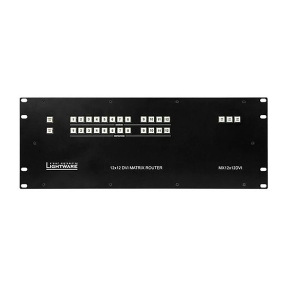
2. Controls and connections 2.1. Front panel view Control lock Source buttons Take / Auto Preset Output lock Destination buttons Power switch Figure 2-1. Front panel view Control Lock Disables or enables front panel operation. When red illuminated, all operations on front panel are prohibited. See section 4.2.1 on page for more information. -
Page 11: Rear View
Standalone MX DVI-Plus family User’s Manual 2.2. Rear view Equipotential connector Input connectors DC Voltage LEDs Serial port CPU LIVE LED Power connector Ethernet port Reset button Output connectors Figure 2-2. Rear view DC voltage indicators LED indicators for internal DC power voltages. Power connector Standard IEC-320 C14 power connector. -
Page 12: Electrical Connections
+6 dB pre-emphasizing circuit, DVI cables up to 15 meters can be used. For using longer cable runs at outputs, use fiber optical DVI transmitters (like Lightware DVI-OPT- TX110) or active DVI repeaters/extenders. No output reclocking is provided. -
Page 13: Rs-232 / Rs-422 Control Port
User’s Manual 2.3.4. RS-232 / RS-422 control port Lightware standalone DVI-Plus matrices can be remote controlled through industry standard 9 pole D-SUB female connector located on the rear panel of the unit. The router can be ordered with RS-232 or RS-422 control port. -
Page 14: Technologies
Lightware MX16x16DVI-Plus matrix, a WUXGA (1920x1200) LCD monitor, and an SXGA (1280x1024) projector. I would like to see the same image on the monitors and the projector. What EDID should I chose on the monitor and the projector?”... -
Page 15: Advanced Edid Management
EDID has been changed. You need to restart your source to make it read out the EDID again. Problem: „I have an MX16x16DVI-Plus and I’m using a Lightware factory preset EDID. I would like to be able to choose from different resolutions, but my source allows only one resolution.”... -
Page 16: Operation
4. Operation 4.1. Power Connect the power cord to the router’s standard IEC-320 C14 AC power input connector. The unit can be switched ON/OFF with the front panel rocker switch. When it is on, the switch illuminates, and the fan operates. After powered on, the unit performs a self-test, and then all front panel buttons light up for one second. -
Page 17: Switching
Standalone MX DVI-Plus family User’s Manual View current state in TAKE mode If all source and destination buttons and TAKE button are unlit (the unit is in TAKE mode, and no input was selected in last 3 seconds), user can verify both input and output connections. -
Page 18: Switching Operations Flowchart
Creating a connection in AUTOTAKE mode Step 1. Press and release the selected destination button. The pressed destination button, and the actually connected source button light up green. If no source is connected (the output is muted) no source button will light up. Step 2. -
Page 19: Preset Operations
Figure 4-2. Switching flowchart in AUTOTAKE mode 4.2.7. Preset operations Lightware matrices have 32 user programmable presets. Each preset stores a configuration regarding all input connections and mute state for all outputs. All presets are stored in a non-volatile memory; the router keeps presets even in case of power down. -
Page 20: Output Lock
4.2.8. OUTPUT LOCK A destination’s state can be locked; this feature prevents an accidental switching to the locked destination in case of important signal. Locking a destination means, that no input selection or muting can be executed on that particular destination. Destinations can be independently locked or unlocked. -
Page 21: Remote Operation
User’s Manual 4.3. Remote operation Lightware matrix routers can be controlled through various interfaces remotely. This makes possible to use such functions that are not accessible via the front panel. Also, this helps system integrators and operators to control multiple devices in a big system through a single user interface. -
Page 22: Multiple Simultaneous Connections
Straight serial cable. 4.3.5. IP settings The Ethernet port can be configured remotely through Lightware Device Controller Software or the built-in website. The factory default IP settings or DHCP mode can be activated quickly through front panel shortcut buttons. To reset the IP configuration perform the following: Resetting the IP address Reset to factory default IP configuration or to DHCP mode with front panel buttons. -
Page 23: Control Protocols
Standalone MX DVI-Plus family User’s Manual 4.3.6. Control protocols Matrix routers can be controlled with multiple control protocols. Lightware routers have a special protocol, but to interoperate with third party devices, a secondary protocol is also provided. Info: Lightware Device Controller software and the built-in website works only with... -
Page 24: Software Control - Using Lightware Device Controller (Ldc)
The matrix can be controlled by a computer through Ethernet or RS-232 port using Lightware Device Controller. The software can be installed to a Windows PC or MAC OS X. The application and the User’s manual can be downloaded from www.lightware.eu. The Windows and the Mac versions have the same look and functionality. - Page 25 Step 6. Verify the settings and if they are correct click Install. (If not, click Back and change the setting.) Step 7. After the installation of the last component the Next button is activated. Click on it. Section 5. Software control – Using Lightware Device Controller (LDC) Page 25 / 89...
-
Page 26: Steps Of The Installation In Case Of Mac Os X
Info: This type of the installer is equal with the Normal install in case of Windows This is an updateable version with the same attributes. Section 5. Software control – Using Lightware Device Controller (LDC) Page 26 / 89... -
Page 27: Ldc Upgrade
Step 1. Run the application. The Device Discovery window appears automatically and the program checks the available updates on Lightware’s website and opens the update window if the LDC found updates. The current and the update version number can be seen in the top of the window and they are shown in this window even with the snapshot install. -
Page 28: Establishing The Connection
If the connection is made via RS-232, click on the Query button next to the appropriate COM port. The name and the serial number of the matrix is loaded. Select the device and click on connect button: Section 5. Software control – Using Lightware Device Controller (LDC) Page 28 / 89... -
Page 29: Crosspoint Menu, Grid View
For the prevention of the unwanted switching, outputs can be locked to any input. Terminal This general-purpose terminal is created mainly for testing and debugging purposes. (For more information, see section 5.10 on page 41.) Section 5. Software control – Using Lightware Device Controller (LDC) Page 29 / 89... -
Page 30: Crosspoint Operations
If an output is locked to an input before preset loading it will also be locked to that input after preset loading, so locked outputs ignore the preset. Section 5. Software control – Using Lightware Device Controller (LDC) Page 30 / 89... -
Page 31: Crosspoint Menu, Tile View
Activate Input switch Toggle Autotake mode Input switch Autotake mode ON/OFF Activate Output switch Execute crosspoint Output switch Take mode changes in Take mode Section 5. Software control – Using Lightware Device Controller (LDC) Page 31 / 89... -
Page 32: Port Tiles
The mode can be also named as ‘Input priority-mode’. In the mode an input port has to be selected at first then the connected output port(s) is/are shown. Thus, the output port(s) connected to the input port can be changed. Section 5. Software control – Using Lightware Device Controller (LDC) Page 32 / 89... - Page 33 Press the desired port button on the port bar on the right; a window pops up where the current port name can be set. Info: Settings of the selected port are also available by pressing the Parameters button. Section 5. Software control – Using Lightware Device Controller (LDC) Page 33 / 89...
-
Page 34: Presets
5.7. Presets Preset operations can be done in Crosspoint submenu on the Preset tab. Each Lightware matrix switcher has 32 preset memories that can be loaded and saved at any time. Info: A preset setting stores a full configuration of all outputs, so preset loading have an effect on every output, except the locked ones. -
Page 35: Edid Menu
Emulated EDID list shows the currently emulated EDID for the inputs. The source column displays the memory location that the current EDID was routed from. Section 5. Software control – Using Lightware Device Controller (LDC) Page 35 / 89... -
Page 36: Changing Emulated Edid
Info: The imported EDID overwrites the selected memory place even if it is not empty. 5.8.5. EDID Summary window Select an EDID from Source panel and press Info button to display the EDID summary. Figure 5-4. EDID Summary Section 5. Software control – Using Lightware Device Controller (LDC) Page 36 / 89... -
Page 37: Editing An Edid
Figure 5-5. Advanced EDID Editor 5.8.7. Creating an EDID Lightware introduced a wizard-like interface for fast and easy EDID creation. With Easy EDID Creator it is possible to create custom EDIDs in four simple steps. By clicking on the Create button below Source panel, Easy EDID Creator is opened in a new window. -
Page 38: Settings Menu
EDID to the actually used Lightware product or/and save it to a file or/and open it in the EDID editor. Info: For more information about creating and EDID by using EEC see the User’s manual of the EDID Editor which is available at www.lightware.eu. -
Page 39: Device Information Tab
Basic information are displayed about the device in this menu: Device type with serial number and installed cards’ type with firmware and hardware version. Figure 5-8. Device information tab Section 5. Software control – Using Lightware Device Controller (LDC) Page 39 / 89... -
Page 40: Log Tab
LDC is able to collect information from the device and save it to a report file. This information package can be sent to Lightware when a problem may arise with the device. Info: When a report is necessary to generate, always let the devices be connected to the device, do not disconnect them. -
Page 41: Terminal
Clicking Yes will open the window. See section on page how to establish the connection. Clicking No will close the pop up window and current connection remains active. Section 5. Software control – Using Lightware Device Controller (LDC) Page 41 / 89... -
Page 42: Web Control - Using Built-In Website
Info: The only way to find out the router’s IP address (if it is not known) is to search for devices with the Lightware Device Controller software. If this is not possible for some reason, the IP address can be reset to factory default (192.168.254.254) with the front panel buttons. -
Page 43: Control Menu
Preset operations Preset operations can be done in the right panel of the Control Set and View Crosspoints page. Lightware matrices have 32 preset memories which can be loaded and saved any time. Info: A preset setting stores a full configuration of all outputs, so preset loading have an effect on every output, except the locked ones. -
Page 44: Edid Menu
6.2. EDID menu By clicking on the EDID MANAGEMENT menu, the EDID Router page appears. When the user enters the menu first, the whole EDID list is being downloaded from the matrix. It may take up to 40 seconds for the first time. After the list is downloaded, the current status of the router’s EDID is shown in the three boxes. - Page 45 Standalone MX DVI-Plus family User’s Manual Figure 6-4. Static EDID routing Info: Switching an EDID to ALL inputs may take several seconds. The user can switch and learn EDIDs also in the Last Attached Monitors EDIDs window. Switching an EDID from this list to an input results dynamic EDID routing. This means that the emulated EDID changes automatically, if a new monitor is attached to the output, by simply copying the data from the monitor.
-
Page 46: Status Menu
Network settings All EDID headers and status (emulated, dynamic, factory, user) Info: User’s issues can be solved easier by Lightware technical support if the generated report file was sent. Standard Report generating Step 1. Click on the “Generate report file button”; the process is started. -
Page 47: Generate Custom Report
6.3.2. Generate custom report The built-in website can run a special command file. After running, a new report file is generated which is useful for Lightware Support Team when debugging. If a command file was sent: Step 1. Save it to the computer. -
Page 48: Configuration Menu
6.4. Configuration menu The network settings of the matrix are displayed under Configuration menu. Figure 6-7. Configuration menu Info: Factory default IP settings can be reloaded by the front panel buttons. See section 4.3.5 on page 22. 6.4.1. Automatic IP Address Configuration The matrix switcher supports three of the most used automatic IP configuration protocols. -
Page 49: Static Ip Address Configuration
Standalone MX DVI-Plus family User’s Manual 6.4.2. Static IP address configuration The user can manually assign an IP address to the unit, and enter related network settings. To assign an IP address manually Step 1. Click on Configuration menu. Step 2. Select Fix IP Configuration. Step 3. -
Page 50: Terminal
If the Autoscroll checkbox is unchecked user should use the scroll bar to see the last commands. 6.6. Support For technical support, please don’t hesitate to contact Lightware Visual Engineering at support@lightware.eu Section 6. Web control – Using built-in website... -
Page 51: About Edid Memory
Standalone MX DVI-Plus family User’s Manual 7. About EDID memory EDID router contains a 164 block non-volatile memory bank. EDID memory is structured as follows: 1..50 ..................Factory Preset EDID list 51..100 ..............User programmable memories 101..116 ( DVI_OUT_1...16)* ......... Last attached monitor’s EDID list 133..148 ( DVI_IN_1...16)* ......... -
Page 52: Programmers Reference
Lightware matrix routers can be controlled with external devices which can communicate according to the router protocol. Lightware routers have a special protocol, but to interoperate with third party devices, a secondary protocol is also provided. -
Page 53: Switching And Control Commands
Standalone MX DVI-Plus family User’s Manual The below example shows a batch command that resulted group switching: One by one commands Batch commands (MX16x16DVI-Plus) → {02@01}CrLf → {02@01}{04@03}CrLf ← (O01 I02)CrLf ← (ALL 02 01 04 01 05 05 05 05 05 05 05 05 05 05 05 05)CrLf →... -
Page 54: View Connection On All Outputs
8.4.4. View connection on all outputs Description: Viewing all outputs’ connection results in different response length, because it depends on the router’s type (length = 16 for MX16x16DVI-Plus, length = 12 for MX12x12DVI-Plus and length = 9 for MX9x9DVI-Plus). The response below supposes a router having 16 outputs. -
Page 55: View Mutes On All Outputs
(length = 16 for MX16x16DVI-Slim, length = 12 for MX12x12DVI-Slim and length = 9 for MX9x9DVI-Plus). The response below supposes a router having 16 outputs. Format Example (MX16x16DVI-Plus) → {vm} Command {VM} (MUT●<M1>●<M2>●<M3> ←... -
Page 56: Unlock Specified Output
Info: Locked outputs are left unchanged. Presets don’t affect output locks. 8.4.12. Preview preset Description: Preview preset <id> without loading. Format Example (MX16x16DVI-Plus) → {vp#3=?} Command {VP#<id>=?} Response (VP#<id>=●<O1>●<O2> ← (VP#3= 02 M02 M01 02 02 01 01 01 ●<O3>●<O4>●<O5>●<O6>... -
Page 57: Rename A Preset
Standalone MX DVI-Plus family User’s Manual Index Legend Explanation ² ² <Ox> <in > <Ox> is connected to <in >, <Ox> is not muted. ² ² <Ox> M<in > <Ox> is connected to <in >, <Ox> is muted. Renaming Presets / Inputs / Outputs Description: Allows storing names for each preset / input / output. -
Page 58: Read An Input's Name
← (PNAME#2=Preset 2)CrLf Response (PNAME#<id>= Preset<id>)CrLf Info: Preset names will be renamed to the factory defaults but will not refreshed in the Lightware Device Controller software. Please click on the Read preset names button to refresh all the preset names. -
Page 59: Reload Default Output Names
Response (ONAME#<id>= Output<id>)CrLf Info: Output names will be renamed to the factory defaults but will not refreshed in the Lightware Device Controller software. Please right click on one output name and choose the Read I/O names item to refresh all the output names. -
Page 60: Reload Factory Default Ip Settings
Gateway 0.0.0.0 Info: IP settings can NOT be changed with this protocol command via Ethernet connection, only via serial port. To change the IP settings via Ethernet, use the Lightware Device Controller software (section 5.9.1 on page 38) or the built-in website (section 6.4). Default settings can be reloaded by the front panel buttons as well (section 4.3.5). -
Page 61: Port Status Commands
Version of LAN controller firmware (webserver). Explanation: MAC address, webcontent and webserver versions are shown. 8.5. Port status commands 8.5.1. Input port status Description: Shows the actual status of the input ports. Format Example (MX16x16DVI-Plus) → {:isd} Command {:ISD} Response (ISD●<INPUT_D>)CrLf ← (ISD 1000000010010001 0000000000000000)CrLf Explanation: Input 1, 9, 12 and 16 has a connected source. -
Page 62: Router Status Commands
MX16x16DVI-Plus single link MX12x12DVI-Plus single link MX9x9DVI-Plus single link Explanation: The connected device is an MX16x16DVI-Plus. 8.6.2. View serial number Description: The router responds its 8-digit serial number. Format Example → {s} Command {S} ← (SN:10170142)CrLf Response (<SERIAL_NUMBER>)CrLf Info: Only the last 4 numbers are written onto the back of the router 8.6.3. -
Page 63: View Installed I/O Cards' Hardware
(SL# 7 Empty Slot)CrLf (SL# 4 Empty Slot)CrLf ← ← Explanation (MX16x16DVI-Plus router): The router reports as if it has two output ad two input cards. 8.6.6. View installed controllers’ firmware Description: Shows the firmware revisions of the installed controllers. -
Page 64: Set Current Control Protocol
8.6.8. Set current control protocol Description: Sets the current RS-232, TCP/IP control protocol (Default is ’1’). Format Example → {p_1} Command {P_x} (PROTOCOL #1 SELECTED!)CrLf ← Response (PROTOCOL●#<x>● SELECTED!)CrLf Legend: <x> stands for the selected protocol. Explanation: Protocol 1 is activated. 8.6.9. -
Page 65: Clear Error List
Note: The router sends (E_S_C) only if the new EDID is different from the earlier one. 8.7.2. Route EDID to the selected input (dynamic) Description: Copies EDID from location <loc> to input <in>. Location <loc> should be 101…109 101...116 (MX16x16DVI-Plus) 101...112 (MX12x12DVI-Plus) (MX9x9DVI-Plus) as opposed to static routing where <loc> should be between 1..100. Format Example →... -
Page 66: Route One Edid To All Inputs
Description: Indexes show the actual input and the number at the given index (<in1>..<inN>) shows which EDID is switched to that particular input where N represents the maximal input number of the given configuration. Format Example 1 (MX16x16DVI-Plus) → {vedid} Command {VEDID} (VEDID●<IN1>●<IN2>●... -
Page 67: View Edid Validity Table
Standalone MX DVI-Plus family User’s Manual 8.7.6. View EDID validity table Description: Shows EDID validity table, which contains information about the EDID states. Format Example (MX16x16DVI-Plus) → {wv} Command {WV} Response (EV●<VALIDITY_TABLE> ← (EV 1111111111111111111111111 )CrLf 1111111111111111111111111111 ← 0000000000000000000000000000 0000000000000000010111111111... -
Page 68: Download Edid Content From The Router
8.7.8. Download EDID content from the router Description: EDID hex bytes can be read directly. The router will issue the whole content of the EDID present on memory location <loc> (256 bytes). Format Example → {we1>} Command {WE<loc>} (EB#1 00 FF FF FF FF FF FF 00 32 Response (EB#<loc>●<B1>... -
Page 69: Delete All Edid From Memory
… (BOOT SLOT 8 STARTED) (BOOT SLOT 8 FINISHED) Explanation (MX16x16DVI-Plus router): The router reports as if it restarted all output and input cards. Info: The response can be seen only if the connection to the router is still alive. -
Page 70: Edid Status Changed
8.8.3. EDID status changed Description: This is sent after all commands which changes the EDID (EDID copy, EDID switch), or after a new EDID source e.g. a new display device is connected to the router. Format Example → {5:101} Command various (E_SW_OK)CrLf ←... -
Page 71: Commands - Quick Summary
Standalone MX DVI-Plus family User’s Manual 9. Commands – Quick summary Switching and control commands See in Command description Command chapter Switch one input to one output 8.4.1 {<in>@<out>} Switch one input to all outputs 8.4.2 {<in>@O} View connection on the specified output 8.4.3 {?<out>} View connection on all outputs... - Page 72 Router Status commands See in Command description Command chapter View product type 8.6.1 View serial number 8.6.2 View Firmware version of the CPU 8.6.3 View CPU firmware compile time 8.6.4 {CT} View Installed I/O cards’ hardware 8.6.5 {IS} View installed controllers’ firmware 8.6.6 {FC} View current control protocol...
-
Page 73: Firmware Upgrade
Bootloader software. 10.1. Installing the Bootloader The matrix router can be upgraded using Lightware Bootloader from a Windows based PC or Laptop via Ethernet. 10.1.1. Installing and launching the Bootloader software Step 1. -
Page 74: Upgrade Process
Step 5. To finish the installation process, click on the Close button. Step 6. To run Lightware Bootloader, find the shortcut icon in Start menu Programs Lightware LW_bootloader_v3_3_1 or on the desktop, and double click on it. -
Page 75: Firmware Upgrade
These settings can be done from the front panel LCD menu or via the supplied Lightware Device Controller software. If you are connecting directly, via a cross UTP cable, you need to set up a fix IP and subnet mask on the Lightware device and the PC. Step 2. Start the application. - Page 76 IP address will establish the connection. Step 4. Connect to a device If the Bootloader finds one or more Lightware devices then they will be listed in the tree view window. This window shows the device type, IP address and serial number of the found Lightware devices.
- Page 77 Standalone MX DVI-Plus family User’s Manual Figure 10-4. Establishing the connection Step 5. Requesting device information After clicking on the YES button, the device name, serial number, IP address, MAC Address and current firmware versions are displayed. Figure 10-5. Details of the device Section 10.
- Page 78 Step 6. Select firmwares to upgrade To upgrade a firmware, click in the field in the line of the controller (marked with pink in the picture below). Click on YES in the pop-up window to modify the path to the new firmware file.
- Page 79 Standalone MX DVI-Plus family User’s Manual Figure 10-7. Enabling the upgrade and Quick Bootload mode Step 8. Starting the upgrade process After selecting all the firmwares which have to be upgraded, click on the UPGRADE SELECTED FIRMWARES button. Then click on YES in the appearing window to start the process.
- Page 80 Step 10. Closing connections After all controllers are upgraded, the Bootloader will close the connection with the Lightware device, which will reboot itself and return to its normal operating mode. Warning Bootloader versions that are older than v3.1.8 will not close the connection and restore the Lightware device until you exit the Bootloader.
- Page 81 Lightware device to perform firmware upgrades. Figure 10-11. Upgrade successful Step 12. Restart the device The Lightware device will restart itself automatically, but it is recommended to completely power down and power up the device after exiting the Bootloader. Section 10. Firmware upgrade...
-
Page 82: Troubleshooting
The computer and the router have to be in the same network. If your computer has multiple network connections (for example WiFi and LAN connections are used simultaneously), check which network the router is connected to. Check the Device Discovery window of the Lightware Device Controller software (see section on page 28). Check the IP settings If you connect the router directly to your computer, you have to set the router’s IP address... -
Page 83: Picture Is Not Displayed Or Distorted
Ethernet device (secondary LAN, Wi-Fi, 3G modem) for the time of the upgrade. If the Bootloader cannot find the Lightware device because the device is connected to the secondary Ethernet adapter (cross UTP connection), you need to disable the primary adapter (Internet). - Page 84 Available devices window will only show the IP address of the Lightware device but not the device type and serial number. The reason for this is that the Lightware device may still be in bootload mode and the controllers cannot send any information about themselves.
-
Page 85: Specifications
MX16x16DVI-Plus MX12x12DVI-Plus MX9x9DVI-Plus * Maximum values are calculated when DVI +5V supplied for external devices but these values include only the consumption of the matrix itself. ** Total power need from the electric outlet, when all output ports are loaded with 500mA on DVI +5V. - Page 86 Signal Data rate: ......all between 25 Mbps and 2.25 Gbps / TMDS channel Channels: ............. 1x TMDS Clock + 3x TMDS Colors Resolutions: all between 640x480 and 1920x1200@60Hz or 2048x1080@60Hz Color depth: ............maximum 36 bits, 12 bit/color Color format ................RGB, YCbCr 4:4:4 HDTV resolutions: ..............
-
Page 87: Mechanical Drawings
Standalone MX DVI-Plus family User’s Manual 12.1. Mechanical Drawings MX16x16DVI-Plus can be seen on the drawings, however the dimensions are the same for all the three models. Dimensions are in mm. Front View Rear View Top View Section 12. Specifications... -
Page 88: Airflow Directions
Left view Right view 12.2. Airflow directions outlet inlet inlet outlet inlet outlet Page 88 / 89 Section 12. Specifications... -
Page 89: Version Applicability
Lightware Visual Engineering warrants this product against defects in materials and workmanship for a period of three years from the date of purchase. The customer shall pay shipping charges when unit is returned for repair. Lightware will cover shipping charges for return shipments to customers.
Need help?
Do you have a question about the MX16x16DVI-Plus and is the answer not in the manual?
Questions and answers