
Related Manuals for Omron CJ1W-DRM21


Summary of Contents for Omron CJ1W-DRM21
- Page 1 Machine Automation Controller CJ-series DeviceNet Units Operation Manual for NJ-series CPU Unit CJ1W-DRM21 DeviceNet Units W497-E1-03...
- Page 2 OMRON. No patent liability is assumed with respect to the use of the information contained herein. Moreover, because OMRON is constantly striving to improve its high-quality products, the information contained in this manual is subject to change without notice.
-
Page 3: Introduction
Introduction Thank you for purchasing a CJ-series CJ1W-DRM21 DeviceNet Unit. This manual contains information that is necessary to use the CJ-series CJ1W-DRM21 DeviceNet Unit for an NJ-series CPU Unit. Please read this manual and make sure you understand the functionality and performance of the NJ-series CPU Unit before you attempt to use it in a control system. -
Page 4: Relevant Manuals
Relevant Manuals Relevant Manuals There are three manuals that provide basic information on the NJ-series CPU Units: the NJ-series CPU Unit Hardware User’s Manual, the NJ-series CPU Unit Software User’s Manual, and the NJ-series Instructions Reference Manual. Most operations are performed from the Sysmac Studio Automation Software. Refer to the Sysmac Stu- dio Version 1 Operation Manual (Cat. -
Page 5: Manual Configuration
Manual Configuration Manual Configuration NJ-series CPU Unit Hardware User’s Manual (Cat. No. W500) Section Description Section 1 This section provides an introduction to the NJ-series Controllers and their features, Introduction and gives the NJ-series Controller specifications. Section 2 This section describes the system configuration used for NJ-series Controllers. System Configuration Section 3 This section describes the parts and functions of the configuration devices in the NJ-... -
Page 6: Nomenclature And Installation
Manual Configuration Sysmac Studio Version 1 Operation Manual (Cat. No. W504) Section Description Section 1 This section provides an overview and lists the specifications of the Sysmac Studio Introduction and describes its features and components. Section 2 This section describes how to install and uninstall the Sysmac Studio. Installation and Uninstallation Section 3 This section describes the basic concepts for designing an NJ-series System with the... - Page 7 Manual Configuration DeviceNet Operation Manual (Cat. No. W267) Section Description Section 1 This section provides an overview of the DeviceNet network, including features, func- Introduction tionality, and types of connected devices such as Masters and Slaves. Section 2 This section describes the DeviceNet network configuration, the wiring method, and Network Configuraion and Wiring details on the connected devices such as connectors.
- Page 8 Manual Configuration GT1 Series DeviceNet Multiple I/O Terminal Operation Manual (Cat. No. 348) Section Description Section 1 This section describes the features, system configuration, types of Units and funci- Multiple I/O Terminal tons provided by the Multiple I/O Terminals. Section 2 This section describes the operating procedures for the Multiple I/O Terminals by Hardeare Setup and Operationa using examples.
- Page 9 Manual Configuration CS/CJ Series DeviceNet Unit Operation Manual (Cat. No. W380) Section Description Section 1 This section provides an overview of the DeviceNet Units and their features. It also Features and System Configuration describes the operating procedure and the specifications of the DeviceNet Units. Section 2 This section describes the nomenclature, functionality and installation of the Nomeclature and Installation...
-
Page 10: Manual Structure
Manual Structure Manual Structure Page Structure The following page structure is used in this manual. Level 1 heading 4 Installation and Wiring Level 2 heading Mounting Units Level 3 heading Level 2 heading Gives the current headings. Level 3 heading 4-3-1 Connecting Controller Components The Units that make up an NJ-series Controller can be connected simply by pressing the Units together... - Page 11 Manual Structure Precaution on Terminology In this manual, “download” refers to transferring data from the Sysmac Studio to the physical Controller and “upload” refers to transferring data from the physical Controller to the Sysmac Studio. For the Sysmac Studio, synchronization is used to both upload and download data. Here, “synchronize” means to automatically compare the data for the Sysmac Studio on the computer with the data in the physical Controller and transfer the data in the direction that is specified by the user.
- Page 12 Manual Structure CJ-series DeviceNet Units Operation Manual for NJ-series CPU Unit(W497)
-
Page 13: Sections In This Manual
Sections in this Manual Sections in this Manual Features and System Index Configuration Nomenclature and Installation Data Exchange with the CPU Unit Remote I/O Master Communications Remote I/O Slave Communications Message Communications Other Functions Communications Timing Troubleshooting and Maintenance Appendices CJ-series DeviceNet Units Operation Manual for NJ-series CPU Unit(W497) -
Page 14: Table Of Contents
CONTENTS CONTENTS Introduction ....................... 1 Relevant Manuals ...................... 2 Manual Configuration ....................3 Manual Structure ....................... 8 Sections in this Manual ..................11 CONTENTS....................... 12 Read and Understand this Manual ................ 16 Safety Precautions ....................19 Precautions for Safe Use..................24 Precautions for Correct Use................... -
Page 15: Contents
CONTENTS Section 3 Data Exchange with the CPU Unit Data Exchange with the CPU Unit..................3-2 3-1-1 Data Flow............................ 3-2 3-1-2 Accessing From the User Program..................... 3-4 Device Variables for CJ-series Unit (Software Switches, Statuses) ........3-9 3-2-1 Software Switches 1 ........................3-9 3-2-2 Software Switches 2 (n + 1CH) .................... - Page 16 CONTENTS Section 5 Remote I/O Slave Communications Slave Remote I/O Communications ..................5-2 5-1-1 Allocation Methods........................5-2 5-1-2 Remote I/O and Slave Communications Specifications .............. 5-3 5-1-3 Procedures for Using Remote I/O Slave Communications ............5-4 Fixed Allocations ........................5-7 5-2-1 Allocated Words ..........................
- Page 17 CONTENTS Troubleshooting........................9-32 9-3-1 CPU Unit's ERR/ALM Indicator Lit or Flashing................. 9-32 9-3-2 Remote I/O Communications Disabled..................9-32 9-3-3 I/O Link Problems ........................9-33 9-3-4 Communications Error Operation Settings ................9-34 9-3-5 Scan List Problems........................9-34 Event Logs ..........................9-35 9-4-1 Overview of the Event Logs......................
-
Page 18: Read And Understand This Manual
WHETHER SUCH CLAIM IS BASED ON CONTRACT, WARRANTY, NEGLIGENCE, OR STRICT LIABILITY. In no event shall the responsibility of OMRON for any act exceed the individual price of the product on which liability is asserted. IN NO EVENT SHALL OMRON BE RESPONSIBLE FOR WARRANTY, REPAIR, OR OTHER CLAIMS... - Page 19 Application Considerations SUITABILITY FOR USE OMRON shall not be responsible for conformity with any standards, codes, or regulations that apply to the combination of products in the customer's application or use of the products. At the customer's request, OMRON will provide applicable third party certification documents identifying ratings and limitations of use that apply to the products.
- Page 20 Performance data given in this manual is provided as a guide for the user in determining suitability and does not constitute a warranty. It may represent the result of OMRON's test conditions, and the users must correlate it to actual application requirements. Actual performance is subject to the OMRON Warranty and Limitations of Liability.
-
Page 21: Safety Precautions
Safety Precautions Safety Precautions Definition of Precautionary Information The following notation is used in this manual to provide precautions required to ensure safe usage of a CJ-series DeviceNet Unit. The safety precautions that are provided are extremely important to safety. Always read and heed the information provided in all safety precautions. - Page 22 Safety Precautions Symbols The circle and slash symbol indicates operations that you must not do. The specific operation is shown in the circle and explained in text. This example indicates prohibiting disassembly. The triangle symbol indicates precautions (including warnings). The specific operation is shown in the triangle and explained in text. This example indicates a precaution for electric shock.
- Page 23 Safety Precautions WARNING During Power Supply Do not touch any of the terminals or terminal blocks while the power is being supplied. Doing so may result in electric shock. Do not attempt to take any Unit apart. In particular, high-voltage parts are present in the Power Supply Unit while power is supplied or immediately after power is turned OFF.
- Page 24 Safety Precautions WARNING Fail-safe Measures Unintended outputs may occur when an error occurs in variable memory or in memory used for CJ-series Units. As a countermeasure for such prob- lems, external safety measures must be provided to ensure safe operation of the system.
- Page 25 Safety Precautions Caution Application Do not touch any Unit when power is being supplied or immediately after the power supply is turned OFF. Doing so may result in burn injury. Wiring Be sure that all terminal screws and cable connector screws are tightened to the torque specified in the relevant manuals.
-
Page 26: Precautions For Safe Use
Precautions for Safe Use Precautions for Safe Use Disassembly and Dropping • Do not attempt to disassemble, repair, or modify any Units. Doing so may result in malfunction or fire. • Do not drop any Unit or subject it to abnormal vibration or shock. Doing so may result in Unit malfunc- tion or burning. - Page 27 Precautions for Safe Use • Do not apply voltages or connect loads to the Output Units or slaves in excess of the maximum rat- ings. • Surge current occurs when the power supply is turned ON. When selecting fuses or breakers for external circuits, consider the above precaution and allow sufficient margin in shut-off performance.
- Page 28 Precautions for Safe Use • Connecting cables or wiring the system • Connecting or disconnecting the connectors The Power Supply Unit may continue to supply power to the rest of the Controller for a few seconds after the power supply turns OFF. The PWR indicator is lit during this time. Confirm that the PWR indicator is not lit before you perform any of the above.
- Page 29 CAT slaves are cut off. During that period, the slave outputs behave according to the slave settings. The time that communications are cut off depends on the EtherCAT network configuration. If the EtherCAT network configuration contains only OMRON EtherCAT slaves, communications are cut off for a maximum of 45 seconds.
- Page 30 Precautions for Safe Use • If the Fail-soft Operation parameter is set to stop operation, process data communications will stop for all slaves when an EtherCAT communications error is detected in a slave. For this reason, if Servo Drives are connected, the Servos for all axes will be turned OFF. Make sure that the Fail-soft Opera- tion parameter setting results in safe operation when a device error occurs.
- Page 31 Precautions for Safe Use Unit Replacement • We recommend replacing the Battery with the power turned OFF to prevent the CPU Unit’s sensitive internal components from being damaged by static electricity and to prevent malfunctions. The Bat- tery can be replaced without turning OFF the power supply. To do so, always touch a grounded piece of metal to discharge static electricity from your body before you start the procedure.
-
Page 32: Precautions For Correct Use
Precautions for Correct Use Precautions for Correct Use Storage, Mounting, and Wiring • Do not operate or store the Controller in the following locations. Operation may stop or malfunctions may occur. • Locations subject to direct sunlight • Locations subject to temperatures or humidity outside the range specified in the specifications •... - Page 33 Precautions for Correct Use Error Processing • In applications that use the results of instructions that read the error status, consider the affect on the system when errors are detected and program error processing accordingly. For example, even the detection of a minor error, such as Battery replacement during operation, can affect the system depending on how the user program is written.
- Page 34 Precautions for Correct Use Battery Replacement • Be sure to install a replacement Battery within two years of the production date shown on the Battery label. • Turn ON the power after replacing the Battery for a CPU Unit that has been unused for a long time. Leaving the CPU Unit unused again without turning ON the power even once after the Battery is replaced may result in a shorter Battery life.
-
Page 35: Regulations And Standards
Concepts EMC Directive OMRON devices that comply with EC Directives also conform to the related EMC standards so that they can be more easily built into other devices or the overall machine. The actual products have been checked for conformity to EMC standards.* Whether the products conform to the standards in the system used by the customer, however, must be checked by the customer. - Page 36 Regulations and Standards Ferrite Core (Data Line Filter): 0443-164151 (manufactured by Fair-Rite Products Co., Ltd.) Impedance specifications 156 Ω 25 MHZ: 250 Ω 100 MHZ: 30 mm 33 mm [Contact] 13 mm Nisshin Electric Co., Ltd. 29 mm Wire the control panel with as thick and short electric lines as possible and ground to 100 Ω min. Keep DeviceNet communications cables as short as possible and ground to 100 Ω...
- Page 37 The NJ-series Controllers comply with the following shipbuilding standards. Applicability to the ship- building standards is based on certain usage conditions. It may not be possible to use the product in some locations. Contact your OMRON representative before attempting to use a Controller on a ship.
-
Page 38: Unit Versions
Gives the lot number and serial number of the Unit. serial number DDMYY: Lot number, @: For use by OMRON, xxxx: Serial number “M” gives the month (1 to 9: January to September, X: October, Y: November, Z: December) MAC address Gives the MAC address of the built-in port on the Unit. - Page 39 Unit Versions Right-click any open space in the Unit Editor and select Production Information. The Production Information Dialog Box is displayed. Simple Display Detailed Display In this example, “Ver.1.00” is displayed next to the unit model. The following items are displayed. CPU Unit CJ-series Units Unit model...
-
Page 40: Related Manuals
Studio. tions of the Sysmac Studio. CJ-series DeviceNet W497 CJ1W-DRM21 Learning about the func- The functions and operating procedures when Units Operation Manual tions and operating proce- the CJ-series DeviceNet Unit is used in an NJ-... -
Page 41: Revision History
Revision History Revision History A manual revision code appears as a suffix to the catalog number on the front and back covers of the manual. W497-E1-03 Cat. No. Revision code Revision code Date Revised content July 2011 Original production March 2012 Corrected errors. - Page 42 Revision History CJ-series DeviceNet Units Operation Manual for NJ-series CPU Unit(W497)
-
Page 43: Features And System Configuration
Features and System Configuration This section provides an overview of the DeviceNet network, and includes features, specifications, and system configurations. 1-1 DeviceNet Unit Features ........1-2 1-2 Specifications . -
Page 44: Devicenet Unit Features
1 Features and System Configuration DeviceNet Unit Features The following are features of the CJ-series DeviceNet Units (CJ1W-DRM21). Multi-vendor Network You can connect DeviceNet devices made by other companies (masters or slaves) to DeviceNet because it conforms to open field network specifications. You can use a combination of valves, sen- sors, and other DeviceNet products to adapt the network to various field-level applications. - Page 45 1 Features and System Configuration User-set Allocations without the CX-Integrator With CJ-series DeviceNet Units, you can allocate remote I/O communications in any area without the CX-Integrator simply by using device variables for CJ-series Unit. If you use the CX-Integrator, you can change the node address order for more flexible I/O alloca- tions.
- Page 46 1 Features and System Configuration Multiple DeviceNet Units on a Single Controller You can mount up to 16 CJ-series DeviceNet Units to a single Contoller. This feature enables greater DeviceNet remote I/O control capacity and ensures that DeviceNet can easily handle line expansion as well as other applications.
- Page 47 1 Features and System Configuration DeviceNet Unit Setup Files (SD Memory Card Backup) You can write setup data (e.g., scan lists) of a DeviceNet Unit as a file to the SD Memory Card mounted in a CPU Unit. This feature greatly simplifies DeviceNet Unit replacement. You can also save a DeviceNet Unit device parameter file (same as setup data file) that is prepared offline with the use of the CX-Integrator on a SD Memory Card, and download the setup data from the SD Mem- ory Card to a DeviceNet Unit.
- Page 48 1 Features and System Configuration Various Connection Methods Normal multi-drop, T-branch multi-drop (with up to three branches), and daisy-chain line connections are available. You can combine these methods to construct a flexible system that suits the floor lay- out. Maximum Network Length of 500 m A network can connect up to 63 Slaves and can handle remote I/O communications of up to 2,000 byes (16,000 points without the CX-Integrator) per DeviceNet Unit.
-
Page 49: Specifications
General Specifications General specifications of the CJ-series DeviceNet Unit conform to those of the NJ-series CPU Units. Functional and Performance Specifications Item Specification DeviceNet Unit model CJ1W-DRM21 Applicable Controller NJ Series Unit classification CPU Bus Unit Applicable unit numbers 0 to F... - Page 50 1 Features and System Configuration Item Specifications Remote I/O Slave allocation method Fixed allo- Select one of the following fixed allocations areas with the use of the master com- (Using the user-defined vari- cations device variables for CJ-series Unit (Fixed Allocations Area Switches 1, 2, munications able for R/W to each alloca- and 3).
- Page 51 1 Features and System Configuration Item Specifications Remote I/O Max. No. of Slaves con- Fixed allocations 63 nodes master nected per DeviceNet Unit User-set By CX- allocations Integrator By device variable for CJ-series Unit Max. No. of I/O points per Fixed allocations 2,048 pts (64 input words, 64 output words) DeviceNet Unit...
- Page 52 1 Features and System Configuration Item Specifications Remote I/O Allocation method (Using the Fixed allo- Select one of the following fixed allocation areas with the use of the Slave user-defined variable for R/W cations device variable for CJ-series Unit (Slave Fixed Allocated Area Switches to the allocation area) 1, 2, and 3).
- Page 53 1 Features and System Configuration Item Specifications Data stored in non-volatile memory (EEPROM) in the Saves the following data settings (same as the Backup file on the SD DeviceNet Unit Memory Card). • Master scan list • Slave scan list •...
- Page 54 1 Features and System Configuration Item Specifications Display section Two indicators (2 colors): Display Unit and network status (Module Sta- tus and Network Status). Two 7-segment indicators: Displays the DeviceNet Unit node address, error code, and node address where an error occurred. 2 dot indicators: Display whether the registration scan list is enabled or not.
-
Page 55: Overview Of Cx-Integrator
1 Features and System Configuration Overview of CX-Integrator You can set allocations for remote I/O communications in any order of node addresses with the CX- Integrator. Users can also set remote I/O communications connections. For details, refer to the CX-Integrator Ver.2. OPERATION MANUAL (Cat. -
Page 56: Basic Operating Procedures
1 Features and System Configuration Basic Operating Procedures 1-4-1 Network Installation Procedure For details on the network installation procedure, refer to the DeviceNet OPERATION MANUAL ( Cat. ). Only a general description is given here. No. W267 Determine a suitable baud rate for the system. -
Page 57: Devicenet Unit Startup Procedure
1 Features and System Configuration 1-4-2 DeviceNet Unit Startup Procedure The basic operating procedures for DeviceNet Unit are described here. Use Sysmac Studio to create programs and to set the Unit. Use the CX-Integrator to set the network configuration. For details on operations of Sysmac Studio, refer to the Sysmac Studio Version 1 Operation Manual (Cat. - Page 58 1 Features and System Configuration Additional Information • The communications power supply and slave power supply, the slave power supply and Con- troller power supply, or all three of these power supplies may be turned ON simultaneously. • When Step 6 is performed, an I/O Setting Check Error occurs when there is a Unit Configura- tion in the CPU Unit which does not match the actual Unit Configuration.
- Page 59 1 Features and System Configuration Allocation of User-defined Variables to the Memory Used for CJ- series Unit With this Unit, the slave areas of the following functions are allocated to the Memory used for CJ-series Unit. • Fixed allocations and user-set allocations (Master) •...
- Page 60 Change "*_Sw1MstrEnblCmd" (Master Enable Switch) to from the CX-Integrator. (Enable TRUE from the Sysmac Studio. (*2) master function in CJ1W-DRM21 property at this time.) Download the above files to the devices on the network. Change "*_Sw1MstrFixAloc1Cmd Input data in advance into to *_Sw1MstrFixAloc3Cmd"...
- Page 61 The order of the procedure is thus Slave Stop Switch (if slave communications are enabled), area allo- cation, and Slave Enable Switch. Note Enable slave communications through CJ1W-DRM21 properties if you use a CX-Integrator. CJ-series DeviceNet Units Operation Manual for NJ-series CPU Unit(W497)
- Page 62 Create a device parameter file to "*_SlavFixAloc3Cmd" "*_SlavAlocTblCfg[0] " from the CX-Integrator. (Enable (Slave Fixed Allocation to "*_SlavAlocTblCfg[5] " Slave function in CJ1W-DRM21 Setting 1 to 3 Switches) (Slave User-set Allocations properties at this time.) Then to TRUE from the Sysmac Studio. Setup Table).
-
Page 63: Message Communications Only (Neither Master Nor Slave Function Used)
1 Features and System Configuration 1-4-3 Message Communications Only (Neither Master nor Slave Function Used) The DeviceNet Unit does not have to be registered in the scan list if it is only used for message commu- nications. You can execute message communications (send and receive) with both master and slave communications disabled. -
Page 64: List Of Usage Methods By Purpose
1 Features and System Configuration List of Usage Methods by Purpose Situation Action Section Design Allocating any Not in order of Set with the use of the CX-Integrator. 4-4-1 Settings words for node through CX- Note Allocations with the use of CX-Integrator: remote I/O addresses Integrator... - Page 65 1 Features and System Configuration Situation Action Section Operation Stopping remote I/O communi- Stop communications with the use of the CX-Inte- 3-2-1 Software cations with all Slaves grator or *_Sw1IOCommStopCmd (Remote I/O Switches 1 Communications Stop Switch). Using a scan list in remote I/O Change *_Sw1SListEnblCmd (Scan List Enable 3-2-1 Software communications (fixed alloca-...
- Page 66 1 Features and System Configuration 1-24 CJ-series DeviceNet Units Operation Manual for NJ-series CPU Unit(W497)
-
Page 67: Nomenclature And Installation
Nomenclature and Installation This section describes the nomenclature and installation of the DeviceNet Unit. 2-1 Nomenclature and Functions ........2-2 2-1-1 Nomenclature and Functions . -
Page 68: Nomenclature And Functions
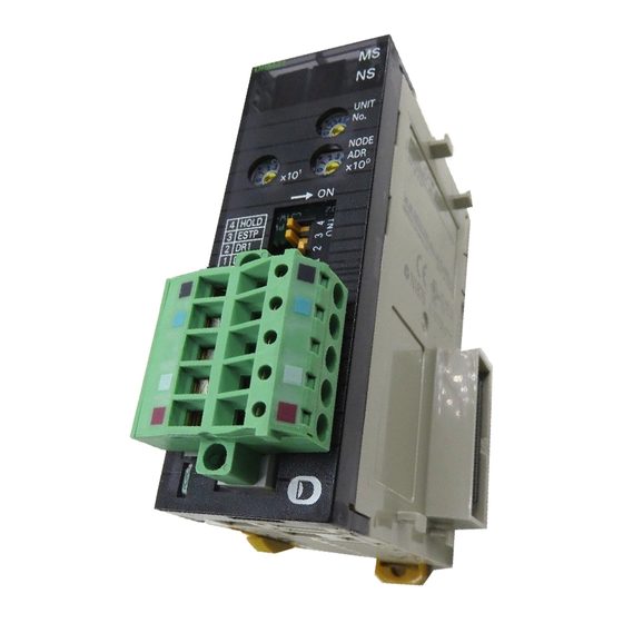
2 Nomenclature and Installation Nomenclature and Functions 2-1-1 Nomenclature and Functions CJ1W-DRM21 DRM21 Indicators Unit No. switch UNIT This switch sets the unit number of the DeviceNet Unit as a one- digit hexadecimal value. NODE Node address switches These switches set the node address as a two-digit decimal value. - Page 69 2 Nomenclature and Installation Status Indicators: MS and NS The MS (Module Status) indicator indicates the status of the node itself and the NS (Network Status) indicator indicates the status of the network. The MS and NS indicators can be green or red and they can be OFF, ON, or flashing (alternating 0.5-s ON and 0.5-s OFF).
- Page 70 2 Nomenclature and Installation Seven-Segment Indicator In addition to the MS and NS indicators, DeviceNet Units have a 2-digit, 7-segment indicator that nor- mally indicates the master node address. When an error occurs, the indicator will alternately show between the error code and the node address of the faulty slave. There are dot indicators at the lower-right corner of each digit.
-
Page 71: Switch Settings
Switch Settings Unit No. Switch CJ1W-DRM21 Use the Unit No. Switch to set the unit number for units as a CPU Special Unit. Set a unique unit number for each CPU set Special Unit installed in the CPU Rack and Expansion Rack with the unit numbers in the unit configuration. - Page 72 DeviceNet network. After correcting the unit number setting, cycle the power to the Controller. Node Address Switches CJ1W-DRM21 Use these switches to set the node address of the Unit. Setting method: Two-digit decimal Setting range: 0 to 63 Note The node address is set to 63 at the factory.
- Page 73 2 Nomenclature and Installation Baud Rate Pins 1 and 2 are used to set the baud rate as shown in the following table. Pin 1 Pin 2 Baud rate 125 kbit/s 250 kbit/s 500 kbit/s Not allowed. Precautions for Safe Use Always turn OFF the Controller before changing the unit number setting.
- Page 74 2 Nomenclature and Installation Communications Connectors Color stickers that match communications cable colors are attached to the communications connec- tors. Match the colors when connecting communications cables to the connectors. These colors are given in the following table Color Signal Black Power line, negative voltage (V–) Blue...
-
Page 75: Installing The Devicenet Unit
2 Nomenclature and Installation Installing the DeviceNet Unit 2-2-1 System Configuration Precautions You can mount up to 16 Units on the CPU Rack or an Expansion Rack per CPU (but no more than 10 Units on one Rack). 2-2-2 Mounting Carefully align the connectors to mount the DeviceNet Unit. -
Page 76: Handling Precautions
2 Nomenclature and Installation 2-2-3 Handling Precautions • Always turn OFF the Controller before you mount or dismount a Unit or connect or disconnect cables. • Provide separate conduits or ducts for the I/O lines to prevent noise from high-tension lines or power lines. -
Page 77: Data Exchange With The Cpu Unit 5
Data Exchange with the CPU Unit This section describes the words allocated to the DeviceNet Unit in the CIO Area and DM Area. These words both enable controlling the DeviceNet Unit and accessing Unit and network status. 3-1 Data Exchange with the CPU Unit ....... . 3-2 3-1-1 Data Flow . -
Page 78: Data Flow
3 Data Exchange with the CPU Unit Data Exchange with the CPU Unit Data exchange between this Unit and the CPU Units uses the I/O port and memory for CJ-series Unit allocated to the DeviceNet Unit. 3-1-1 Data Flow The CPU Units and CJ-series DeviceNet Units exchange data as shown in the table and chart below. Data exchange type Access methods from AT specification... - Page 79 3 Data Exchange with the CPU Unit CPU Unit DeviceNet Unit I/O port User program Software switch, Software switch, status data status data Software switches (I/O refresh) Device variable AT specification for CJ-series Unit Status (I/O refresh) Allocations setting table, Allocations setting table, slave detailed slave detailed...
-
Page 80: Accessing From The User Program
3 Data Exchange with the CPU Unit Device Variable for CJ-series Unit Device variables for CJ-series Units are variables for which AT is specified for the I/O port explained below. The user program uses device variables for CJ-series Unit to access the Configuration Unit such as DeviceNet Unit. - Page 81 3 Data Exchange with the CPU Unit Data type I/O port, memory used for CJ-series Unit Access method Setting/status Software switches/sta- Operation Data Device variables tus data for CJ-series Unit Allocations setting table, slave detailed status Slave area Fixed allocation 1 to 3 Fixed allocation 1 OUT: CIO 3200 to CIO User-defined vari-...
- Page 82 3 Data Exchange with the CPU Unit How to Create User-defined Variables In this unit, slaves are allocated to the memory used for CJ-series Unit when you use the functions shown below. • Fixed allocations and user-set allocations (Master) • Fixed allocations and user-set allocations (Slave) Use the Sysmac Studio to register user-defined variables to the variable table.
- Page 83 3 Data Exchange with the CPU Unit The user-defined variables and I/O data of each slave are allocated as follows: I/O Data User-defined variable name Address OUT slave I/O data (node address 0) Slave1_OutData_A[0] 3200 OUT slave I/O data (node address 63) Slave1_OutData_A[63] 3263 The user program accesses the slave with WORD-type variables.
- Page 84 3 Data Exchange with the CPU Unit Additional Information For details on memory used for CJ-series Unit, variable allocation, and user-defined variable registration, refer to the Sysmac Studio Version 1 Operation Manual (Cat. No. W504). CJ-series DeviceNet Units Operation Manual for NJ-series CPU Unit(W497)
-
Page 85: Device Variables For Cj-Series Unit (Software Switches, Statuses)
3 Data Exchange with the CPU Unit Device Variables for CJ-series Unit (Software Switches, Statuses) When you operate and reference software switches and statuses, use the following device variables for CJ-series Unit allocated to the I/O port of this Unit. Name of device variable for Type Area... - Page 86 3 Data Exchange with the CPU Unit WORD-type device variables for CJ-series Unit holding all switch functions contained in Software Switches 1 are shown below. Name of device variable for Type Area Function CJ-series Unit *_Sw1Cmd WORD Software Bits have the following functions: Switches 1 Bit 00: Scan List Enable Switch Bit 01: Scan List Clear Switch...
- Page 87 3 Data Exchange with the CPU Unit BOOL-type device variables for CJ-series Unit separating functions per each switch contained in Software Switches 1 are shown below. Name of device variable for Type Area Function CJ-series Unit *_Sw1SListEnblCmd BOOL Scan List <Operation specifications>...
- Page 88 3 Data Exchange with the CPU Unit Name of device variable for Type Area Function CJ-series Unit *_Sw1IOCommStartCmd BOOL Remote I/O <Operation specifications> Communi- FALSE→TRUE: cations Starts remote I/O communications. Start Switch Note 1 The switch is ignored if remote I/O communications are already running.
- Page 89 3 Data Exchange with the CPU Unit Name of device variable for Type Area Function CJ-series Unit *_Sw1MstrEnblCmd BOOL Master <Operation specifications> Enable FALSE→TRUE: Switch Enables master communications. (The Unit automatically restarts.) Once enabled, the Unit will function as a Master until *_Sw1MstrDsblCmd (Master Stop Switch) is changed to TRUE, regard- less of whether the power is turned OFF...
- Page 90 3 Data Exchange with the CPU Unit Name of device variable for Type Area Function CJ-series Unit *_Sw1MstrFixAloc1Cmd BOOL Master <Operation specifications> Fixed Allo- FALSE→TRUE: cation Set- Sets the I/O allocation area for when the ting 1 scan list is disabled to the following words. Switch (Same as default.
- Page 91 3 Data Exchange with the CPU Unit Name of device variable for Type Area Function CJ-series Unit *_Sw1MstrAlocCmd BOOL Master <Operation specifications> User-set FALSE→TRUE: Allocations Reads setting data from Switch *_MstrAlocTblCfg[0] to *_MstrAlocTblCfg[5] (Master User-set Allocations Setup Table) and registers the scan list.
- Page 92 3 Data Exchange with the CPU Unit Name of device variable for Type Area Function CJ-series Unit *_Sw1CycleTmTmpSet BOOL Temporary <Operation specifications> Setting FALSE→TRUE: Switch for Reads setting data from Communi- *_CommCycleTmCfg (Communications cations Cycle Time Setting) and temporarily Cycle Time changes the communications cycle time.
- Page 93 3 Data Exchange with the CPU Unit Name of device variable for Type Area Function CJ-series Unit *_Sw1CycleTmSetCmd BOOL Communi- <Operation specifications> cations FALSE→TRUE: Cycle Time Reads setting data from Setting *_CommCycleTmCfg (Communications Switch Cycle Time Setting) to change the com- munications cycle time and to store the communications cycle time in non-volatile memory in the Unit.
-
Page 94: Software Switches 2 (N + 1Ch)
3 Data Exchange with the CPU Unit 3-2-2 Software Switches 2 (n + 1CH) Use one of the following device variables for CJ-series Unit to operate Software Switches 2 from the user program: • WORD-type device variable for CJ-series Unit holding all switch functions contained in Software Switches 2 •... - Page 95 3 Data Exchange with the CPU Unit BOOL-type device variables for CJ-series Unit separating functions per each switch contained in Soft- ware Switches 2 are shown below. Name of device variable for Type Area Function CJ-series Unit *_Sw2SlavEnblCmd BOOL Slave <Operation specifications>...
- Page 96 3 Data Exchange with the CPU Unit Name of device variable for Type Area Function CJ-series Unit *_Sw2SlavFixAloc1Cmd BOOL Slave Fixed <Operation specifications> Allocation FALSE→TRUE: Setting 1 Sets the Slave Fixed Allocation Area to Switch the following words. • OUT 1 area (input to the CPU Unit): CIO 3370 (1 word allocated) •...
- Page 97 3 Data Exchange with the CPU Unit Name of device variable for Type Area Function CJ-series Unit *_Sw2SlavAlocCmd BOOL Slave User <Operation specifications> Allocations FALSE→TRUE: Switch Reads setting data from *_SlavAlocTblCfg[0] to *_SlavAlocTblCfg[5] (Slave User-set Allo- cations Setup Table) and registers slave user-set allocations.
- Page 98 3 Data Exchange with the CPU Unit Name of device variable for Type Area Function CJ-series Unit *_Sw2FileRestoreCmd BOOL Unit Setup <Operation specifications> File Restore FALSE→TRUE: Switch Reads Unit settings (for details on the scan list, communications cycle time set- tings, etc., refer to 7-1 SD Memory Card Backup Functions on page 7-2.) from the file within the SD Memory Card of the...
-
Page 99: Master Cos Send Switches
3 Data Exchange with the CPU Unit 3-2-3 Master COS Send Switches Use one of the following device variables for CJ-series Unit is used to operate Master COS Send Switches. • *_MstrCOSSendCmd LWORD-type device variable for CJ-series Unit that is capable of operating switches for all slaves (node addresses 0 to 63). -
Page 100: Disconnect/Connect Switches
3 Data Exchange with the CPU Unit 3-2-4 Disconnect/Connect Switches Use one of the following device variables for CJ-series Unit is used to operate Disconnect/Connect Switches from the user program. • *_CnctCmd LWORD-type device variable for CJ-series Unit that is capable of operating switches for all slaves (node addresses 0 to 63). -
Page 101: Unit Status 1
3 Data Exchange with the CPU Unit The following device variable for CJ-series Unit is used when you execute an individual function for each slave. Name of device variable for Type Area Function CJ-series Unit *_CnctNdCmd[0 to 63] BOOL Discon- <Operation specifications>... - Page 102 3 Data Exchange with the CPU Unit The following device variables for CJ-series Unit are used to reference individual information. Name of device variables for Type Area Function CJ-series Unit *_UnitErr BOOL Unit Error <Operation specifications> TRUE: Displays DeviceNet Unit operating errors. *_UnitErr (Unit Error) changes to TRUE if any bit from 01 to 15 in *_Unit1Sta (Unit Status 1) is TRUE (OR information of bits...
- Page 103 3 Data Exchange with the CPU Unit Name of device variable for Type Area Function CJ-series Unit *_SlavFunErr BOOL Slave Func- <Operation specifications> tion Error TRUE: Indicates that at least one slave error occurred. Refer to *_Slav1Sta (Slave Sta- tus 1). The slave errors are as follows: •...
- Page 104 3 Data Exchange with the CPU Unit Name of device variable for Type Area Function CJ-series Unit *_NdAdrDupErr BOOL Node <Operation specifications> Address TRUE: Duplicated Indicates a duplicate node address check Error error when the Unit starts up. The Unit goes offline and all communica- tions stop.
- Page 105 3 Data Exchange with the CPU Unit Name of device variable for Type Area Function CJ-series Unit *_SendTimeoutErr BOOL Send Time- <Operation specifications> out Error TRUE: Indicates that a send timeout occurred due to one of the following factors: • No slaves present. •...
-
Page 106: Unit Status 2
3 Data Exchange with the CPU Unit 3-2-6 Unit Status 2 The following device variables for CJ-series Unit is used to reference all information of Unit Status 2. Name of device variable for Type Area Function CJ-series Unit *_Unit2Sta WORD Unit Status Bit 00: Online Status Bit 01: Remote I/O Communications Sta-... - Page 107 3 Data Exchange with the CPU Unit Name of device variable for Type Area Function CJ-series Unit *_IOCommSta BOOL Remote I/O <Operation specifications> Communi- TRUE: cations Sta- Indicates that remote I/O communications are being performed for the master func- tion. Note This variable only indicates the start of remote I/O communications, and does not indicate whether data was...
- Page 108 3 Data Exchange with the CPU Unit Name of device variable for Type Area Function CJ-series Unit *_SlavConnTypSta BOOL Automatic <Operation specifications> Slave Con- TRUE: nection Indicates that the connection type was automatically set in the slave scan list. This device variable for CJ-series Unit is valid only with slave communications enabled.
-
Page 109: Master Status 1
3 Data Exchange with the CPU Unit 3-2-7 Master Status 1 The following device variable for CJ-series Unit is used to reference all information of Master Status 1. Name of device variable for Type Area Function CJ-series Unit *_Mstr1Sta WORD Master Sta- Bit 00: Verification Error tus 1... - Page 110 3 Data Exchange with the CPU Unit Name of device variable for Type Area Function CJ-series Unit *_Mstr1IOErr BOOL Remote I/O <Operation specifications> Communi- TRUE: cations Indicates that a remote I/O communica- Error tions timeout occurred during remote I/O communications with slaves. Note Remote I/O communications stop if DIP switch pin 3 (remote I/O com- munications stop/continue with a...
- Page 111 3 Data Exchange with the CPU Unit Name of device variable for Type Area Function CJ-series Unit *_Mstr1IORefErr BOOL Master I/O <Operation specifications> Refresh TRUE: Error Indicates that the I/O memory in the CPU Unit that is to be refreshed is not present during I/O refreshing for the master.
- Page 112 3 Data Exchange with the CPU Unit Name of device variable for Type Area Function CJ-series Unit *_Mstr1FixAlocErr BOOL Master <Operation specifications> Fixed Allo- TRUE: cation Area Indicates that an error occurred in one of Setting the following operations: Failed •...
- Page 113 3 Data Exchange with the CPU Unit Name of device variable for Type Area Function CJ-series Unit *_Mstr1CycleTmSetErr BOOL Communi- <Operation specifications> cations TRUE: Cycle Time Indicates that an error occurred when set- Setting ting *_Sw1CycleTmTmpSet (Temporary Failed Setting Switch for Communications Cycle Time) or *_Sw1CycleTmSetCmd (Com- munications Cycle Time Setting Switch).
-
Page 114: Master Status 2
3 Data Exchange with the CPU Unit 3-2-8 Master Status 2 The following device variables for CJ-series Unit indicate the status of master I/O allocations. Information of MstrIOAlocSta (Master I/O Allocation Status) can be referenced from *_Mstr2Sta (Master Status 2). Master I/O Allocation Status Codes and Allocation Statuses Code Details... -
Page 115: Slave Status 1
3 Data Exchange with the CPU Unit 3-2-9 Slave Status 1 The following device variable for CJ-series Unit is used to reference all information of Slave Status 1. Name of device variable for Type Area Function CJ-series Unit *_Slav1Sta WORD Slave Sta- Bit 00: Reserved by system tus 1... - Page 116 3 Data Exchange with the CPU Unit Name of device variable for Type Area Function CJ-series Unit *_Slav1IO2Err BOOL Remote I/O <Operation specifications> Communi- TRUE: cations Indicates that a communications error Error for occurred in the OUT 2/IN 2 Slave I/O con- OUT 2/IN 2 nection.
- Page 117 3 Data Exchange with the CPU Unit Name of device variable for Type Area Function CJ-series Unit *_Slav1IORefErr BOOL Slave I/O <Operation specifications> Refresh TRUE: Error Indicates that the I/O memory in the CPU Unit that is to be refreshed is not present during I/O refreshing for the slave func- tion.
- Page 118 3 Data Exchange with the CPU Unit Name of device variable for Type Area Function CJ-series Unit *_Slav1FixAlocErr BOOL Slave Fixed <Operation specifications> Allocation TRUE: Area Set- Indicates that an error occurred in one of ting Failed the following operations: •...
- Page 119 3 Data Exchange with the CPU Unit Name of device variable for Type Area Function CJ-series Unit *_Slav1COSSendErr BOOL COS Send <Operation specifications> Failed TRUE: Indicates that an attempt was made to send COS to a master using *_Sw2SlavCOSSendCmd (Slave COS Send Switch), but the transmission failed.
- Page 120 3 Data Exchange with the CPU Unit Name of device variable for Type Area Function CJ-series Unit *_Slav1IO2CommSta BOOL Remote I/O <Operation specifications> Communi- TRUE: cations for Indicates that an I/O connection is estab- OUT 2/IN 2 lished for OUT 2/IN 2 and the slave is con- ducting normal remote I/O communications with the master.
-
Page 121: Slave Status 2
3 Data Exchange with the CPU Unit 3-2-10 Slave Status 2 *_Slav2Sta (Slave Status 2) is used to reference 2 types of information: Master Node Address and Slave I/O Allocation Status. Use *_MstrNdAdrSta (Node Address of The Remote Master for Slave Communications) and *_SlavIOAlocSta (Slave I/O Allocation Status) to reference individual information. -
Page 122: 3-2-11 Registered Slave Table
3 Data Exchange with the CPU Unit 3-2-11 Registered Slave Table This table indicates the slaves that are registered in the master scan list. Bits 00 to 63 of LWORD-type device variable for CJ-series Unit *_RegSlavTblSta correspond to slaves at node addresses 0 to 63. This table is updated when the Unit starts up and when a scan list is registered. -
Page 123: 3-2-12 Normal Slave Table
3 Data Exchange with the CPU Unit 3-2-12 Normal Slave Table This table indicates the slaves that are communicating normally with the master. Bits 00 to 63 of LWORD-type device variable for CJ-series Unit *_NormSlavTblSta correspond to slaves at node addresses 0 to 63. -
Page 124: C200H Master Replacement Master Status 1
3 Data Exchange with the CPU Unit 3-2-13 C200H Master Replacement Master Status 1 To simplify changes to user programs for a C200H DeviceNet Master Unit (C200HW-DRM21-V1), C200H Master Replacement Master Status 1, which has the same bit configuration as Master Status Area 1, is provided for this Unit. - Page 125 3 Data Exchange with the CPU Unit Name of device variable for Type Area Function CJ-series Unit *_CMstrCfgErr BOOL Configura- This bit changes to TRUE if any of the fol- tion Error lowing device variables for CJ-series Unit is TRUE: •...
- Page 126 3 Data Exchange with the CPU Unit Name of device variable for Type Area Function CJ-series Unit *_CMstrSListDsblSta BOOL Invalid Scan This is the same as *_SListDsblSta (Scan List Data List Disable Status). Flag Default: FALSE *_CMstrErr BOOL Master This bit changes to TRUE if bits 0, 1, or 3 Error to 7 of *_CMstrSta (C200H Master Replacement Master Status 1) is TRUE.
-
Page 127: Device Variables For Cj-Series Unit (Allocations Setting Table, Slave Detailed Status)
3 Data Exchange with the CPU Unit Device Variables for CJ-series Unit (Allocations Setting Table, Slave Detailed Status) The following device variables for CJ-series Unit are used to set Allocations Setting Tables, reference setup statuses and reference detailed statuses of slaves. *_CommCycleTmCfg UINT RW Communications Cycle Time Setting... - Page 128 3 Data Exchange with the CPU Unit Additional Information The Unit calculates the optimum communications cycle time and stores it internally. If a value smaller than that is set, then the value calculated by the Unit will be used. 3-52 CJ-series DeviceNet Units Operation Manual for NJ-series CPU Unit(W497)
-
Page 129: Master User-Set Allocations Setup Table
3 Data Exchange with the CPU Unit 3-3-2 Master User-set Allocations Setup Table Use device variables for CJ-series Unit to specify the I/O words for Master User-set Allocations. You can only set OUT block 1 and IN block 1 with this table. Additional Information OUT blocks 1 and 2 and IN block 1 and 2 can be set from CX-Integrator. - Page 130 3 Data Exchange with the CPU Unit Areas and Word Ranges Code Area name in memory for CJ-series Unit Word range The block is not allocated. CIO Area (CIO) 0 to 6143 Data Memory (DM) 0 to 32767 Work Area (WR) 0 to 511 Holding Area (HR) 0 to 511...
- Page 131 3 Data Exchange with the CPU Unit Allocation Size Setup Table Set the following allocation size setup tables in the memory used for CJ-series Units of the CPU Unit to use the Master User-set Allocations Setup Table. The number of bytes set in the allocation size setup table are allocated in word units in order of node addresses for OUT block 1 and then IN block 1.
-
Page 132: Slave User-Set Allocations Setup Table
3 Data Exchange with the CPU Unit 3-3-3 Slave User-set Allocations Setup Table The I/O areas in the Memory for CJ-series Units specified here for the slave OUT 1 area and slave IN 1 area are used if the slave function is enabled with *_Sw2SlavAlocCmd (Slave User Allocations Switch). You can update I/O allocations for the slaves by setting this table and changing *_Sw2SlavAlocCmd (Slave User Allocations Switch) to TRUE. - Page 133 3 Data Exchange with the CPU Unit Note You cannot use Holding Area H512 and its subsequent holding areas, or EM Area Bank D and its subse- quent banks. Slave User-set Allocations Setup Table Setting Results Code Description Details 16#0000 Completed normally 16#1101 No area...
-
Page 134: Communications Cycle Time Reference Table
3 Data Exchange with the CPU Unit 3-3-4 Communications Cycle Time Reference Table You can use this table to store the present, maximum and minimum communications cycle times in milliseconds. All the values in this table are cleared from the Unit and the maximum and minimum values are updated with new values of when *_Sw1CycleTmClrCmd (Communications Cycle Time Reference Table Clear Switch) is changed to TRUE. - Page 135 3 Data Exchange with the CPU Unit Name of device variable for Type Area Function CJ-series Unit *_MstrAlocRefTblSta[4] UINT First word in Stores the first word for IN 1 area. IN block 1 Data range: 0 to 32767 Default: 0 *_MstrAlocRefTblSta[5] UINT No.
-
Page 136: Slave User-Set Allocations Reference Table
3 Data Exchange with the CPU Unit 3-3-6 Slave User-set Allocations Reference Table You can access the slave block settings in the Slave User-set Allocations Reference Table. You can use a maximum of two OUT and two IN areas (OUT 1, IN 1, OUT 2, and IN 2 areas) for slave communica- tions and you can access their area and size in the table. -
Page 137: Slave Detailed Status
3 Data Exchange with the CPU Unit Name of device variable for Type Area Function CJ-series Unit *_SlavAlocRefTblSta[11] UINT Slave IN 2 Stores the first word for IN 2 area. area size The OUT 1 block is not allocated if the value is 0. - Page 138 3 Data Exchange with the CPU Unit The following device variables for CJ-series Unit are used to reference individual information. Name of device variable for Type Area Function CJ-series Unit *_Nd0Err BOOL Slave Error <Operation specifications> for node TRUE: *_Nd63Err addresses Indicates that a remote I/O communica- 0 to 63...
- Page 139 3 Data Exchange with the CPU Unit Name of device variable for Type Area Function CJ-series Unit *_Nd0IOErr BOOL Slave <Operation specifications> Remote I/O TRUE: *_Nd63IOErr Communi- Indicates that an error occurred in remote cations I/O communications with the correspond- Error for ing slave.
- Page 140 3 Data Exchange with the CPU Unit Name of device variable for Type Area Function CJ-series Unit *_Nd0IOCommSta BOOL Remote I/O <Operation specifications> Communi- TRUE: *_Nd63IOCommSta cations Flag Indicates that normal remote I/O commu- at node nications were conducted with the corre- addresses sponding slaves at all set connections.
-
Page 141: Remote I/O Master Communications
Remote I/O Master Communications This section describes the remote I/O communications performed as a DeviceNet mas- ter by the DeviceNet Unit. 4-1 Master Remote I/O Communications ......4-2 4-1-1 Allocations . -
Page 142: Master Remote I/O Communications
4 Remote I/O Master Communications Master Remote I/O Communications Remote I/O communications are used to automatically transfer data between slaves and the CPU Unit without any special programming in the CPU Unit under which the Master Unit is mounted. Master Communications NJ-series CPU Unit CJ-series DeviceNet Unit (master) Remote I/O communications... - Page 143 4 Remote I/O Master Communications Fixed Allocations You can use *_Sw1MstrFixAloc1Cmd to *_Sw1MstrFixAloc3Cmd (Master Fixed Allocation Setting 1 to 3 Switch) to specify where a slave is allocated in the following fixed allocation areas 1 to 3. The output (OUT) block and the input (IN) block are allocated to a certain area as shown below in the order of node address.
- Page 144 4 Remote I/O Master Communications With CX-Integrator When using the CX-Integrator, you can allocate four blocks to each slave: Output (OUT) blocks 1 and 2 and input blocks 1 and 2. Each block is a maximum of 500 words. To access the allocated area from the user program, a user-defined variable that specifies the AT specification of that area needs to be defined.
-
Page 145: Remote I/O Master Specifications
4 Remote I/O Master Communications 4-1-2 Remote I/O Master Specifications Item Specifications Slave alloca- Fixed allo- Select one of the following fixed allocations areas with the use of *_Sw1MstrFixAloc1Cmd tion methods cations to *_Sw1MstrFixAloc3Cmd (Master Fixed Allocation Setting 1 to 3 Switch). Allocated Size Fixed Alloca-... -
Page 146: Precautions On The Number Of Master Units
4 Remote I/O Master Communications Item Specifications Max. No. of Fixed allocations 2,048 pts (64 input words, 64 output words) I/O points per User-set By device 16,000 pts (500 input words x 1 block, 500 output words x 1 block) DeviceNet allocations variable for... - Page 147 4 Remote I/O Master Communications Pattern One Master Unit con- Multiple Master Units con- Multiple Master Units con- nected on a single net- nected on a single network nected to a single CPU Unit work Precautions Same as previous net- •...
-
Page 148: Procedure For Using Remote I/O Master
4 Remote I/O Master Communications 4-1-4 Procedure for Using Remote I/O Master Fixed Allocations for Remote I/O Turn ON the communications, slave, and Controller power supplies. *1 Turn ON the communications power supply prior to turning ON the slave power supply or the slaves may not go online. - Page 149 Switch the CPU Unit to PROGRAM mode. 1) Create a network configuration online on the CX-Integrator. 2) Enable master communications in the CJ1W-DRM21 properties. 3) Create master device parameters. 3) Read the project file, go online, and 4) Save the data as a project file.
- Page 150 4 Remote I/O Master Communications User-set Remote I/O Allocations Using Device Variable for CJ-series Unit Turn ON the communications, slave, and Controller power supplies. Note Turn ON the communications power supply prior to turning ON the slave power supply or the slaves may not go online.
-
Page 151: Scan List
4 Remote I/O Master Communications Scan List 4-2-1 Scan List A scan list is used to register the slaves with which the Master Unit communicates in DeviceNet remote I/O communications. It is the basis on which the Master Unit communicates with slaves. The Master Unit does not contain a scan list by default. -
Page 152: Scan List Enabled And Scan List Disabled
4 Remote I/O Master Communications Creating the Scan List The way that a scan list is prepared varies with the allocation method as shown below. Allocations Fixed allocations User-set allocations User-set allocations using device variable for from the CX-Integrator CJ-series Unit How to create scan list With the CPU Unit in PRO- With the CPU Unit in PRO-... -
Page 153: Backing Up The Scan List
4 Remote I/O Master Communications Precautions for Correct Use Precautions for Correct Use The scan list is automatically enabled when user-set allocations are set using the device vari- ables for CJ-series Unit or the CX-Integrator. If the list is subsequently cleared using *_Sw1SListClrCmd (Scan List Clear Switch), fixed allocations (1 to 3) will be used for remote I/O communications when the scan list is disabled. -
Page 154: Fixed Allocations
4 Remote I/O Master Communications Fixed Allocations 4-3-1 Allocated Words If fixed allocation is used, allocated words are in the following I/O (CIO) area in the memory used for CJ- series Unit. You can select an area of words from one of three fixed allocation areas. Use *_Sw1MstrFixAloc1Cmd to *_Sw1MstrFixAloc3Cmd (Master Fixed Allocation Setting 1 to 3 Switch) to select the allocation area. -
Page 155: Allocation Procedures
4 Remote I/O Master Communications 4-3-2 Allocation Procedures Step 1: Place the CPU Unit in PROGRAM mode. Step 2: Change the Master Enable Switch to TRUE If the master communications have been disabled (if *_MstrEnblSta (Master Function Enabled Sta- tus) is set to FALSE), change *_Sw1MstrEnblCmd (Master Enable Switch) to TRUE to enable mas- ter communications. - Page 156 4 Remote I/O Master Communications Step 6: Define the User-defined Variable Define a user-defined variable for the area to which each slave is allocated. By using the user- defined variable, the user program can access the allocation area of the slave. Below is an example of a user-defined variable in which fixed allocations area 1 is selected.
- Page 157 4 Remote I/O Master Communications Fixed Allocations Area 2 OUT blocks are allocated to slaves from CIO 3400 to CIO 3463 and IN blocks are allocated to slaves from CIO 3500 to CIO 3563 in the memory used for CJ-series Unit. To access the output (OUT) block and the input (IN) block from the user program, allocate a user-defined variable to the applica- ble area.
-
Page 158: Changing System Components
4 Remote I/O Master Communications Fixed Allocations Area 3 OUT blocks are allocated to slaves from CIO 3600 to CIO 3663 and IN blocks are allocated to slaves from CIO 3700 to CIO 3763 in the memory used for CJ-series Unit. To access the output (OUT) block and the input (IN) block from the user program, allocate a user-defined variable to the applica- ble area. -
Page 159: Fixed Allocations Example
4 Remote I/O Master Communications 4-3-4 Fixed Allocations Example This example shows the allocations that are used when Fixed Allocations 1 are used for the following slaves. Node address Outputs Inputs Product 0 pts 8 pts 8-pt Transistor Input Terminal (DRT1-ID08) 8 pts 0 pts... -
Page 160: User-Set Allocations
4 Remote I/O Master Communications User-set Allocations With a CJ-series DeviceNet Unit, you can allocate remote I/O communication slaves in any area of a memory used for CJ-series Unit (CIO, WR, HR, DM, or EM) with the use of one of the following meth- ods: •... - Page 161 4 Remote I/O Master Communications Precautions for Correct Use Precautions for Correct Use Functions will vary as shown below depending on whether allocations are set with the use of CX- Integrator or through device variable for CJ-series Unit (Master User-set Allocations Setup Table.) •...
-
Page 162: Settings Through Cx-Integrator
4 Remote I/O Master Communications 4-4-1 Settings through CX-Integrator You can allocate slaves in any order for the following blocks: OUT block 1, OUT block 2, IN block 1, and IN block 2. To access the area where the slave is allocated from the user program, a user-defined variable that specifies the AT specification of that area needs to be defined. - Page 163 4 Remote I/O Master Communications Allocation Procedures Step 1 Set the area, start word, and words allocated for each block with the use of the CX-Integrator. Step 2 Allocate words to all node addresses in each block as shown below with the use of the CX-Integra- tor.
- Page 164 4 Remote I/O Master Communications d) The start bit for node addresses can be bit 00 or bit 08. If it is bit 08 however, 2 or more bytes cannot be allocated as shown below. Start byte e) Multiple masters cannot share the same slave. Master Master Slave...
-
Page 165: Settings Through Device Variables For Cj-Series Unit (Master User-Set Allocations Setup Table)
4 Remote I/O Master Communications CX-Integrator Setting Methods Refer to CX-Integrator Ver.2. OPERATION MANUAL (Cat. No. W464). 4-4-2 Settings through Device Variables for CJ-series Unit (Master User-set Allocations Setup Table) All slaves are allocated words in order of node addresses in two blocks: OUT block 1 and IN block 1. In the block area, the first word is set with *_MstrAlocTblCfg[0 to 3]. - Page 166 4 Remote I/O Master Communications Allocation Procedures Step 1: Set the CPU Unit to PROGRAM Mode. Step 2: Set the Master Enable Switch to TRUE. Make sure that master communications was disabled by checking to see if *_MstrEnblSta (Master Function Enabled Status) is FALSE, and then set to TRUE the *_Sw1MstrEnblCmd (Master Enable Switch) to enable master communications.
- Page 167 4 Remote I/O Master Communications Step 4: Set the Allocation Size Setup Table Specify the area and first word l in this table at words *_MstrAlocTblCfg[4] (Allocation size setup table area) and *_MstrAlocTblCfg[5] (First word in the allocation size setup table 1). Allocate user-defined variables to the areas on the allocation size setup table.
- Page 168 4 Remote I/O Master Communications Example: This is not necessary. OUT block 1 IN block 1 Node address 01 Node address 01 Node address 02 Node address 02 Node address 03 3 The start bit for node addresses must always be bit 00, and never bit 08. 4 Multiple masters cannot share the same slave.
- Page 169 4 Remote I/O Master Communications Example Settings for User-set Allocations through Device Variables for CJ-series Unit This example uses the following settings for unit number 0. • OUT block 1 area and first word: WR (4), 50CH (50) • IN block 1 area and first word: WR (4), 100CH (100) •...
- Page 170 4 Remote I/O Master Communications Master User-set Allocations Setup Table Name of device variables for Name Setting (function) CJ-series Unit *_MstrAlocTblCfg[0] OUT block 1 area 4 (WR) *_MstrAlocTblCfg[1] First word in OUT block 1 50 (50 words) *_MstrAlocTblCfg[2] IN block 1 area 4 (WR) *_MstrAlocTblCfg[3] First word in IN block 1...
-
Page 171: Starting And Stopping Remote I/O Communications
4 Remote I/O Master Communications Starting and Stopping Remote I/O Communications 4-5-1 Starting Remote I/O Communications Remote I/O communications start automatically after the Unit is restarted or the Controller is reset, including when the power is turned ON. The *_Mstr1IOCommSta (I/O Data Communications Status) is changed to TRUE when remote I/O communications is started with at least one slave. -
Page 172: Example Of User Program For Remote I/O Communications
4 Remote I/O Master Communications Example of User Program for Remote I/O Communications When user program are written for remote I/O communications, make sure it performs I/O processing with a slave under the following conditions: • *_Mstr1IOCommSta (I/O Data Communications Status) is changed to TRUE. •... -
Page 173: Errors That May Occur In Remote I/O Communications
4 Remote I/O Master Communications Errors that May Occur in Remote I/O Communications The following errors may occur during remote I/O communications. Condition Error Details Results Indicators 7-seg- ment indica- Error *_Mstr1StruE Duplicate The same I/O word is allocated to Reconnect with MS: Not occurs in... - Page 174 4 Remote I/O Master Communications Condition Error Details Results Indicators 7-seg- ment indica- Fixed or I/O communications error A timeout occurred during remote Reconnect with MS: Not user-set I/O communications. (The Slave the error Slave related allocations response timed out 6 times in a and continue row or an error occurred 3 times remote I/O com-...
-
Page 175: Remote I/O Slave Communications 7
Remote I/O Slave Communications This section describes the remote I/O communications performed as a DeviceNet slave by the DeviceNet Unit. 5-1 Slave Remote I/O Communications ....... 5-2 5-1-1 Allocation Methods . -
Page 176: Remote I/O Slave Communications
5 Remote I/O Slave Communications Slave Remote I/O Communications A CJ-series DeviceNet Unit can function as a Slave Unit in remote I/O communications and a single CJ- series DeviceNet Unit can function as both a Master Unit and a Slave Unit. This section describes Slave communications. -
Page 177: Remote I/O And Slave Communications Specifications
5 Remote I/O Slave Communications 5-1-2 Remote I/O and Slave Communications Specifications Item Specifications Allocation Fixed allo- Select one of the following fixed allocations areas 1, 2, and 3 using *_Sw2SlavFixAloc1Cmd to method cations *_Sw2SlavFixAloc3Cmd (Slave Fixed Allocation Setting 1 Switch to Slave Fixed Allocation Setting 3 Switch). -
Page 178: Procedures For Using Remote I/O Slave Communications
5 Remote I/O Slave Communications 5-1-3 Procedures for Using Remote I/O Slave Communications Fixed Allocations for Remote I/O Switch the CPU Unit to PROGRAM mode. Change "*_Sw2SlavDsblCmd" (Slave Stop Switch) to TRUE from the Sysmac Studio. Change "*_Sw2SlavFixAloc1Cmd" to "*_Sw2SlavFixAloc3Cmd" (Slave Fixed Allocation Setting 1 to 3 Switch) to TRUE from the Sysmac Studio. - Page 179 Define user-defined variables in the area to which I/O data is allocated. Switch the CPU Unit to RUN mode. Slave remote I/O communications will begin. Note Enable slave communications in CJ1W-DRM21 Properties if the CX-Integrator is used. CJ-series DeviceNet Units Operation Manual for NJ-series CPU Unit(W497)
- Page 180 5 Remote I/O Slave Communications User-set Remote I/O Allocations Using Device Variables for CJ-series Unit Switch the CPU Unit to PROGRAM mode. Change "*_Sw2SlavDsblCmd" (Slave Stop Switch) to TRUE from the Sysmac Studio. 1) Input data in advance into "*_SlavAlocTblCfg[0]" to "*_SlavAlocTblCfg[5]" (Slave User-set Allocations Setup Table) and the Allocation Size Setup Table from the Sysmac Studio.
-
Page 181: Fixed Allocations
5 Remote I/O Slave Communications Fixed Allocations 5-2-1 Allocated Words If fixed allocation is used, allocated words are in the following I/O (CIO) area in the memory used for CJ- series Unit. select words from three fixed allocations areas. *_Sw2SlavFixAloc1Cmd to *_Sw2SlavFixAloc3Cmd (Slave Fixed Allocation Setting 1 to 3 Switch) to select the allocation area. - Page 182 5 Remote I/O Slave Communications Name of device Name Fixed allocation area Allocated output Allocated input (IN) variables for CJ- (OUT) area area series Unit (master to slave) (slave to master) *_Sw2SlavFixAloc1C Slave Fixed Allocation Fixed allocation area 1 CIO 3370 CIO 3270 Setting 1 Switch *_Sw2SlavFixAloc2C...
-
Page 183: User-Set Allocations
5 Remote I/O Slave Communications User-set Allocations With a CJ-series DeviceNet Unit, you can allocate remote I/O communication slaves in any area of a memory used for CJ-series Unit (CIO, WR, HR, DM, or EM) using one of the following methods: •... - Page 184 5 Remote I/O Slave Communications Specified areas in memory used for CJ-series Unit Master User-set block order First word specified Slave output OUT area (OUT) area 1 First word specified Slave input IN area (IN) area 1 First word specified Slave input IN area (IN) area 2...
- Page 185 5 Remote I/O Slave Communications Connection Types and Allocated I/O Areas The following table shows the relationship between various connection combinations and the allo- cated areas that are applicable with those connections. Specified connection OUT 1 area IN 1 area IN 2 area type Poll...
-
Page 186: Settings Through Device Variables For Cj-Series Unit (Slave User-Set Allocations Setup Table)
5 Remote I/O Slave Communications 5-3-2 Settings through Device Variables for CJ-series Unit (Slave User- set Allocations Setup Table) You can allocate words for the OUT 1 area (master to Slave Unit) and IN 1 area (Slave Unit to mas- ter) from any specified location for the memory used for CJ-series Unit specified in the settings in the device variables for CJ-series Unit. - Page 187 5 Remote I/O Slave Communications Name of device variables for Type Name Range CJ-series Unit *_SlavAlocTblCfg[4] UINT First word in slave IN 1 area 0 to 32767 *_SlavAlocTblCfg[5] UINT IN 1 area size 0 to 200 *_SlavAlocTblCfgSta WORD Setting Results of Slave User-set 16#0000 to Allocations Setup FFFF...
- Page 188 5 Remote I/O Slave Communications • OUT block 1 area and first word: WR (4), 50 (50CH (50)), 20-byte size = 10 words (20) • IN block 1 area and first word: WR (4), 100 (100CH (100)), 10-byte size = 5 words (10) •...
- Page 189 Message Communications This section describes explicit message communications sent from the user program in the CPU Unit. 6-1 Overview ........... . . 6-2 6-1-1 Outline of Message Communications .
-
Page 190: Overview
• Message communications with DeviceNet devices from other companies can be performed. • Explicit messages from OMRON PLCs (with C200H-series DeviceNet Units and CVM1/ CV-series DeviceNet Units) can be received. Explicit messages can be sent to OMRON PLCs (with C200H I/O Link Units). -
Page 191: Explicit Message Communications
Explicit Message Communications You can send service requests to DeviceNet masters and slaves made by other manufacturers and OMRON slaves (C200H I/O Link Units, CS-series DeviceNet Units, etc.) with the use of explicit mes- sages defined for DeviceNet. Service requests to read/write CPU Unit status and I/O memory can also be received from PLCs with... -
Page 192: Message Communications Specifications
6 Message Communications 6-1-3 Message Communications Specifications Supported CPU Unit functions Specification Unit model number CJ1W-DRM21 Max. No. of communications Explicit mes- nodes per Unit sages Communications instructions Explicit SendCmd instruction DeviceNet Sends explicit messages to DeviceNet masters/slaves made by other... -
Page 193: Message Communications Error Indications
6 Message Communications 6-1-4 Message Communications Error Indications There are two ways to obtain information on communications errors that occur in message communica- tions: 1) Using the error history in the DeviceNet Unit and 2) Using DeviceNet Unit displays, indicators, and Master Status Areas. - Page 194 6 Message Communications Error Indicators Unit status 1 Error his- tory code 7-segment (Hex) indicator* Network power error No change Not lit *_NetPwrErr 0341 is 1. Send timeout *_SendTimeo 0342 utErr is 1. Routing table error Flashing No change *_RTblErr is 021A Node address duplicated No change...
-
Page 195: Sending Explicit Messages
6 Message Communications Sending Explicit Messages CJ-series DeviceNet Units can send explicit messages. Explicit messages can be sent to the following destinations. • DeviceNet masters or slaves made by other manufacturers • CS/CJ-series DeviceNet Unit Example NJ-series CPU Unit CJ-series DeviceNet Unit Other manufacturer DeviceNet master or slave or CJ-series DeviceNet Unit Explicit messages can be sent... - Page 196 6 Message Communications 6-2-1 Sending Explicit Messages The command code 28 01 can be used to send explicit DeviceNet messages to OMRON special slaves and DeviceNet masters/slaves made by other manufacturers. OMRON special slaves or Slave or Master by other...
- Page 197 6 Message Communications Response Block Normal Response 534 bytes max. Command Response No. of Byte Service Data Code Code Received Service Code Destination Node Address (remote node) Error Responses The following response is returned if an error occurs for the explicit message. Command Response No.
- Page 198 6 Message Communications Service Data Word (2-byte) data and double-word (4-byte) data in the Service Data (such as channel data and error clear codes) shall conform to the command format of specifying the lower byte (L) first, followed by the higher byte (H).
-
Page 199: Sending Explicit Messages Using Sendcmd Instruction
6 Message Communications 6-2-2 Sending Explicit Messages Using SendCmd Instruction The SendCmd (send command) instruction can be used in the CPU Unit user program of the CJ-series DeviceNet Unit to send explicit messages. The explicit message command data that contains the command code 2801 hex at its beginning is sent. The explicit message response is received after the command code 2801 hex and the end code. - Page 200 6 Message Communications Operation Here, an example of reading the vendor code (OMRON vendor code: 002F hex) from the DeviceNet slave (unit address: 16#10). Command source Destination Sdata[0] Sdata[1] SendCmd Execute Done Sdata[7] Command code DstNetAdr Busy interpretation Sdata[8] CommPort...
- Page 201 6 Message Communications Additional Information You can send explicit messages to OMRON slaves and DeviceNet devices made by other manu- facturers by setting the command code to 28 01. In this case, set the response monitoring time to at least the value set for the message monitor- ing timer (default: 2s).
- Page 202 6 Message Communications Determining the SendCmd instruction execution completion SendCmd_instance.Done OperatingEnd SendCmd_instance.Error Trigger reception RS_instance Operating Trigger _Port_isAvailable DeviceNet_OnlineSta OperatingEnd Reset1 Communications parameters settings Operating InDNetAdr.NetNo:=0; // Network address settings InDNetAdr.NodeNo:=0; InDNetAdr.UnitNo:=BYTE#16#10; InOption.isNonResp:=FALSE; // Response monitoring and retry settings InOption.TimeOut:=20; InOption.Retry:=2;...
- Page 203 6 Message Communications Precautions for Correct Use Precautions for Correct Use The message service function does not guarantee that a given message will reach the remote node. Messages may be lost during communication due to noise, etc. When the message ser- vice function is used, normally the node that issues an instruction performs resend to avoid the above condition.
-
Page 204: Receiving Explicit Messages
6 Message Communications Receiving Explicit Messages CJ-series DeviceNet Unit contains a PLC Object. The Unit will receive messages addressed to the PLC Object, process service requests addressed to the CPU Unit, and return responses. The following services are provided by the PLC Object. •... -
Page 205: List Of Plc Object Services
6 Message Communications 6-3-1 List of PLC Object Services PLC Objects provide the following services. Status Read/Write for CPU Units Services Service Class ID Instance ID Request ser- Contents code vice data CPU Unit Informa- 0E Hex 2F Hex 00 Hex Attribute ID = Reads the operating mode of the tion Read... - Page 206 6 Message Communications Information Read for CPU Units (Service Code: 0E Hex) Reads CPU Unit information, including Operating Mode, Controller Errors, and the CPU Unit model. Command Block Class ID Attribute ID Service Code Instance ID Note A body format of either 8 bits or 16 bits is possible. Response Block Service Code Attribute Value...
- Page 207 6 Message Communications Note The codes for the above modes are 1-word (2-byte) data and are returned in low byte first. For example, for PROGRAM mode, the code is returned as 01 Hex followed by 00 Hex. • CPU Unit Errors (when Attribute ID = 65 Hex) The CPU Unit controller error data is returned in 1-byte (2-digit) hexadecimal format.
- Page 208 6 Message Communications Note The specified code for the above operating modes are 1-word (2-byte) data, and are speci- fied with the low byte first. For example, for PROGRAM mode, the code is specified as 01 Hex followed by 00 Hex. Accordingly, the low to high bytes for the above codes are set as high to low bytes in I/O memory, when setting the input variable CmdDat of the SendCmd instruction as data.
- Page 209 6 Message Communications CPU Unit Status Read (Service Code: 40 Hex) This PLC Object service reads detailed status (operation status, operating mode) from the CPU Unit. Command Block Service Code Instance ID Class ID Note A body format of either 8 bits or 16 bits is possible. Response Block Service Code Detailed status...
- Page 210 6 Message Communications Command Block Class ID Address L No. of bytes read Service Code Instance ID Address H * A body format of either 8 bits or 16 bits is possible. Response Block Service Code Word data L Word data L Word data H Word data H Read data (200 bytes max.)
- Page 211 6 Message Communications Word Data Read (Service Code: 1D Hex) Word Data Read reads any I/O memory area data in the memory used for CJ-series Unit in a CPU Unit with a CJ-series DeviceNet Unit mounted. The read word data is in word units. The response block is returned from low to high bytes.
- Page 212 6 Message Communications Byte Data Write (Service Code: 1E Hex) Byte Data Write writes data to any I/O memory area in the memory used for CJ-series Unit in a CPU Unit with a CJ-series DeviceNet Unit mounted. The write word data is in byte units. The command block is specified from high to low bytes, as shown in the following diagram.
- Page 213 6 Message Communications Word Data Write (Service Code: 1F Hex) Word Data Write writes data to any I/O memory area in the memory used for CJ-series Unit in a CPU Unit with a CJ-series DeviceNet Unit mounted. The write word data is in word units. The response block is returned from low to high bytes.
- Page 214 6 Message Communications 6-26 CJ-series DeviceNet Units Operation Manual for NJ-series CPU Unit(W497)
-
Page 215: Other Functions
Other Functions This section describes connecting to Sysmac Studio via the DeviceNet and the SD Memory Card backup function. 7-1 SD Memory Card Backup Functions ......7-2 7-1-1 Outline of Functions . -
Page 216: Sd Memory Card Backup Functions
7 Other Functions SD Memory Card Backup Functions The DeviceNet Unit stores the following setup data in the internal non-volatile memory. • Master scan lists • Slave scan lists • Message monitoring timer lists • Communications cycle time settings • Master/Slave functions enabled/disabled settings Note Backup is possible only when scan lists are enabled. -
Page 217: Outline Of Functions
7 Other Functions 7-1-1 Outline of Functions Backing Up Unit Setup Files Saves all internal Unit setup data to the SD Memory Card mounted to the CPU Unit. Method: By changing the software switch *_Sw2FileBkupCmd (Unit Setup File Backup Switch) to TRUE, save the internal Unit setup data on an SD Memory Card as unit setup files. -
Page 218: File Names
7 Other Functions Saving Files from CX-Integrator to SD Memory Card You can restore the data setup file into a DeviceNet Unit by saving a device parameter file (extension .dvf) for this DeviceNet Unit created with CX-Integrator to an SD Memory Card with the file name DNnn- BKUP.dvf (nn: unit number (2-digit hexadecimal), mounting it in the CPU Unit, and changing the software switch *_Sw2FileRestoreCmd (Unit Setup File Restore Switch) to TRUE. -
Page 219: Communications Timing
Communications Timing This section describes the time required for remote I/O communications and message communications. 8-1 Remote I/O Communications Characteristics ..... . . 8-2 8-1-1 Communications Cycle Time . -
Page 220: Remote I/O Communications Characteristics
Characteristics This section describes the characteristics of remote I/O communications when the DeviceNet Unit is used as a master in combination with OMRON DeviceNet slaves. Use this section for reference when planning operations that require precise I/O timing. The equations provided here are valid under the following conditions: •... - Page 221 8 Communications Timing Communications Cycle Time Calculation Use the equations shown below to calculate the communications cycle time (T ) for a network with one Master. Note that if the result of this calculation is less than 2 ms, the actual communications cycle time will be 2 ms.
- Page 222 8 Communications Timing Input Slaves with Less Than 8 Bytes of Input = 0.016 ×T × S + 0.06 × T + 0.05 [ms] The number of Input Slave input words The baud rate factor (500 kbit/s: T = 2; 250 kbit/s: T = 4;...
-
Page 223: Calculating Guidelines For I/O Response Times
8 Communications Timing 8-1-2 Calculating Guidelines for I/O Response Times This section describes the formulas to use to calculate the minimum and maximum I/O response times for the following configuration. Refer to 8-1-1 Communications Cycle Time for the communications cycle time and the communications time per slave, which are used in the formulas. - Page 224 8 Communications Timing is the smallest value that meets the following condition. RMMAX × T > T RMMAX RFNJ + Task period × (3 + y) + T RFNJ INNJMAX OUTNJMAX y = ((Number of CPU Bus Units + 1) × 1 ms) ÷ Task period Note Truncate the decimal portion of y and use the resulting integer in the formula.
-
Page 225: More Than One Master In Network
8 Communications Timing 8-1-3 More than One Master in Network The following equation shows the remote I/O communications cycle time (T ) when there is more than one master in the network. An example for two masters is used. First, the network is divided into two groups: Master A and the slaves in remote I/O communications with it and master B and the slaves in remote I/O communications with it. -
Page 226: System Startup Time
8 Communications Timing 8-1-4 System Startup Time Master Function This section describes the system startup time (estimated) for a network operating with the scan list enabled. The system startup time is the delay from when the controller is reset or restarted including turning ON the DeviceNet Unit (master) until remote I/O communications begin. - Page 227 8 Communications Timing Additional Information Refer to 3-2 Device Variables for CJ-series Unit (Software Switches, Statuses) for details on the Master Status Area. Slave Function It takes approximately 12 seconds from the time that the Controller is reset or restarted, including when the power is turned ON to the DeviceNet Unit (slave), until remote I/O communications with the master begin.
-
Page 228: Message Communications
8 Communications Timing Message Communications 8-2-1 Message Communications Time The message communications time is the time required from the time a Master Unit starts to send a message over the Network to another node until the Master Unit completes sending the message. The following equation can be used to compute the approximate message communications time. -
Page 229: Calculating The Maximum Message Response Time
8 Communications Timing 8-2-2 Calculating the Maximum Message Response Time The message response time is the time required from the time a DeviceNet Unit starts to receive an I/O memory read request message (BYTE DATA READ explicit message) until the DeviceNet Unit com- pletes sending the response message to the client. - Page 230 8 Communications Timing • CPU Unit's processing time: T x 6 + T x 2 = T The following time is required to process data with other clients before the CPU Unit starts processing. 7 other clients/2 = Approximately cycle time x 3 If one processing requires two CPU Unit task periods, the time will be as follows: CPU Unit task period x 3 x 2 = CPU Unit task period x 6 CPU Unit's processing time: T...
-
Page 231: Troubleshooting And Maintenance
Troubleshooting and Maintenance This section describes error processing, periodic maintenance operations, and trouble- shooting procedures needed to keep the DeviceNet network operating properly. We recommend reading through the error processing procedures before operation so that operating errors can be identified and corrected more quickly. 9-1 Troubleshooting with the DeviceNet Unit Indicators . -
Page 232: Troubleshooting With The Devicenet Unit Indicators
9 Troubleshooting and Maintenance Troubleshooting with the DeviceNet Unit Indicators 9-1-1 Determining Operating Status from the Indicators Indicator status Network/Unit status Comments 7-segment Initializing with CPU Unit Initialization processing with the CPU Unit is in progress. Restart the DeviceNet Unit if this status continues for an extended period of time. - Page 233 9 Troubleshooting and Maintenance CJ-series DeviceNet Units Operation Manual for NJ-series CPU Unit(W497)
-
Page 234: Troubleshooting Errors Occurring In The Devicenet Unit
9 Troubleshooting and Maintenance 9-1-2 Troubleshooting Errors Occurring in the DeviceNet Unit Indicators Error Error Likely cause DeviceNet Unit Error category response 7-seg- (Hex) ment Master Remote Pin 3 on the master's DIP • Remote I/O communica- 0346 function I/O com- switch is set to stop com- tions as a master will munica-... - Page 235 9 Troubleshooting and Maintenance Status of C200H Master Replacement Status of device variables Correction Master Status 1 for CJ-series Units *_CMstrSta*_CMstrSta *_CMstrErr (Master Error) and *_Mstr1IOErr (Remote I/O Communica- Perform error processing according to *_CMstrIOErr (Communication Error) are tion Error), *_UnitErr (Unit Error) and the cause: TRUE or *_CMstrErr (Master Error) and *_MstrFunErr (Master Function Error)
- Page 236 9 Troubleshooting and Maintenance Indicators Error Error Likely cause DeviceNet Unit Error category response 7-seg- (Hex) ment Software Incorrect There was an error in the • The only response is the settings setting parameters specified in error code displayed on errors the user settings and the the 7-segment indicator.
- Page 237 9 Troubleshooting and Maintenance Status of C200H Master Replacement Status of device variables Correction Master Status 1 for CJ-series Units *_CMstrSta*_CMstrSta Check the parameters in the user set- tings and try the operation again. Execute software switch operations one at a time. *_CMstrErr (Master Error) and *_Mstr1StruErr (Structure Error), Set the slaves' node addresses again.
- Page 238 9 Troubleshooting and Maintenance Indicators Error Error Likely cause DeviceNet Unit Error category response 7-seg- (Hex) ment Structure The size of the slave's The master will periodi- 0343 (flashing) input and/or output area cally attempt to reconnect error exceeded 200 bytes. with the slave with the (Unsup- (Occurs with the scan list...
- Page 239 9 Troubleshooting and Maintenance Status of C200H Master Replacement Status of device variables Correction Master Status 1 for CJ-series Units *_CMstrSta*_CMstrSta *_CMstrErr (Master Error) and *_Mstr1StruErr (Structure Error), Use slaves with input and output *_CMstrStruErr (Structure Error) are *_UnitErr (Unit Error) and *_MstrFunErr areas of 200 bytes max.
- Page 240 9 Troubleshooting and Maintenance Indicators Error Error Likely cause DeviceNet Unit Error category response 7-seg- (Hex) ment Master Verification The CX-Integrator is set to The master will periodi- 0344 (flashing) function check the vendor and the cally attempt to reconnect error slave's vendor does not with the slave with the veri-...
- Page 241 9 Troubleshooting and Maintenance Status of C200H Master Replacement Status of device variables Correction Master Status 1 for CJ-series Units *_CMstrSta*_CMstrSta *_CMstrErr (Master Error) and *_Mstr1VefyErr (Verification Error), Inspect the slave and then create the *_CMstrVefyErr (Verification Error) are *_UnitErr (Unit Error) and *_MstrFunErr scan list again.
- Page 242 9 Troubleshooting and Maintenance Indicators Error Error Likely cause DeviceNet Unit Error category response 7-seg- (Hex) ment OFF or Network Network The communications Records the error in the 0341 power sup- power supply is not being error log. (flash- ply error supplied properly from the As long as power is not network.
- Page 243 9 Troubleshooting and Maintenance Status of C200H Master Replacement Status of device variables Correction Master Status 1 for CJ-series Units *_CMstrSta*_CMstrSta *_CMstrErr (Master Error) and *_NetPwrErr (Network Power Error) and Check the network power supply and *_CMstrSendErr (Send Error) are TRUE. *_UnitErr (Unit Error) are TRUE.
- Page 244 9 Troubleshooting and Maintenance Indicators Error Error Likely cause DeviceNet Unit Error category response 7-seg- (Hex) ment OFF or Network Transmis- A transmission request As long as transmission 0342 sion time- was not completed nor- timeout is in effect, remote (flashing) out error mally for one of the follow-...
- Page 245 9 Troubleshooting and Maintenance Status of C200H Master Replacement Status of device variables Correction Master Status 1 for CJ-series Units *_CMstrSta*_CMstrSta *_CMstrErr (Master Error) and *_SendTimeoutErr (Send Timeout Check the following: *_CMstrSendErr (Send Error) are TRUE. Error) and *_UnitErr (Unit Error) are •...
- Page 246 9 Troubleshooting and Maintenance Indicators Error Error Likely cause DeviceNet Unit Error category response 7-seg- (Hex) ment Memory Master There is an error in the • Records the error in the 021A (flashing) access scan list contents of the master error log.
- Page 247 9 Troubleshooting and Maintenance Status of C200H Master Replacement Status of device variables Correction Master Status 1 for CJ-series Units *_CMstrSta*_CMstrSta *_CMstrErr (Master Error) and *_UnitErr (Unit Error), *_MstrFunErr Clear the scan list and register the *_CMstrCfgErr (Configuration Error) are (Master Function Error) and scan list again or use the CX-Integra- TRUE.
- Page 248 9 Troubleshooting and Maintenance Indicators Error Error Likely cause DeviceNet Unit Error category response 7-seg- (Hex) ment Memory Memory An error occurred in the Registers an error record 0602 (flashing) access access Unit's non-volatile mem- with error code 0602 in the error ory itself.
- Page 249 9 Troubleshooting and Maintenance Status of C200H Master Replacement Status of device variables Correction Master Status 1 for CJ-series Units *_CMstrSta*_CMstrSta *_CMstrErr (Master Error) and *_UnitErr (Unit Error) and *_MemErr Replace the Unit if the error recurs. *_CMstrMemErr (Unit Memory Error) are (Unit Memory Error) are TRUE.
- Page 250 9 Troubleshooting and Maintenance Indicators Error Error Likely cause DeviceNet Unit Error category response 7-seg- (Hex) ment Red (lit) Network Node The master's node • The Unit will go offline 0211 address address is duplicated on and communications will duplication another node.
- Page 251 9 Troubleshooting and Maintenance Status of C200H Master Replacement Status of device variables Correction Master Status 1 for CJ-series Units *_CMstrSta*_CMstrSta *_CMstrErr (Master Error) and *_UnitErr (Unit Error) and Check the node addresses set on *_CMstrNdDupErr (Node Address Dupli- *_NdAdrDupErr (Node Address Dupli- other nodes in the network.
- Page 252 9 Troubleshooting and Maintenance Indicators Error Error Likely cause DeviceNet Unit Error category response 7-seg- (Hex) ment CPU Unit CPU Unit A parity error occurred • Records the error in the 0012 (flashing) exchange memory while reading the routing error log and continues faulty table.
- Page 253 9 Troubleshooting and Maintenance Status of C200H Master Replacement Status of device variables Correction Master Status 1 for CJ-series Units *_CMstrSta*_CMstrSta *_CMstrErr (Master Error) and *_RTblErr (Routing Table Error) and Register the routing table in the CPU *_CMstrCfgErr (Configuration Error) are *_UnitErr (Unit Error) are TRUE.
- Page 254 9 Troubleshooting and Maintenance Indicators Error Error Likely cause DeviceNet Unit Error category response 7-seg- (Hex) ment CPU Unit CPU Unit Servicing from the CPU • Records the error in the 0002 (flashing) exchange service Unit is not performed at error log.
- Page 255 9 Troubleshooting and Maintenance Status of C200H Master Replacement Status of device variables Correction Master Status 1 for CJ-series Units *_CMstrSta*_CMstrSta There is no status notification because There is no status notification because Inspect the CPU Unit's operating envi- communications with the CPU Unit are communications with the CPU Unit are ronment.
- Page 256 9 Troubleshooting and Maintenance Indicators Error Error Likely cause DeviceNet Unit Error category response 7-seg- (Hex) ment Slave Remote A timeout occurred during If slave has outputs, the 0345 (flashing) function I/O com- remote I/O communica- status of those outputs is munica- tions using the slave func- determined by the...
- Page 257 9 Troubleshooting and Maintenance Status of C200H Master Replacement Status of device variables Correction Master Status 1 for CJ-series Units *_CMstrSta*_CMstrSta *_Slav1IO1Err (Remote I/O Communi- Check the following: cations Error for OUT1/IN1) or • Master Operation is normal *_Slav1IO2Err (Remote I/O Communi- •...
-
Page 258: Error Log Functions
9 Troubleshooting and Maintenance Error Log Functions Errors detected by the DeviceNet Unit are stored in the error log along with the date and time of their occurrence. You can monitor the error log by using the CX-Integrator. Refer to the CX-Integrator Operation Manual (Cat. No. W464) for error log monitoring operations. 9-2-1 Error Log Table Error Log Table... -
Page 259: Error Codes And Detail Codes
9 Troubleshooting and Maintenance 9-2-2 Error Codes and Detail Codes Error Error Detail code Record code stored in First byte Second byte (Hex) EEPROM 0001 CPU Unit watchdog timer error 00 Hex 00 Hex 0002 CPU Unit service monitoring error (Servicing Monitoring time (ms) from the CPU Unit is not performed at fixed intervals.) - Page 260 9 Troubleshooting and Maintenance Error Error Detail code Record code stored in First byte Second byte (Hex) EEPROM 0101 Transmission failed because the local node is Explicit message communications command: not participating in the network. Bit 15: OFF Bits 14 to 8: 0 0105 Transmission failed because of a node address Bit 7: ON...
- Page 261 9 Troubleshooting and Maintenance Error Error Detail code Record code stored in First byte Second byte (Hex) EEPROM 0343 Structure error 01 Hex: I/O area dupli- Slave's node address cation 02 Hex: I/O area range exceeded 03 Hex: Unsupported slave 0344 Verification error 01 Hex: Non-existent...
-
Page 262: Troubleshooting
CPU Unit's manual to correct the problem. • All of a CJ1W-DRM21 Unit's indicators will be OFF when a CPU Bus Unit error has occurred. • Restart the Unit. If operation is not restored even after the Unit is restarted, replace the Unit. -
Page 263: I/O Link Problems
• Check whether the slaves are operating properly. When an OMRON DeviceNet slave is being used, refer to the DeviceNet Slaves Operation Manual (Cat. No. W347). When another company's DeviceNet slave is being used, refer to that slave's user's manual. -
Page 264: Communications Error Operation Settings
9 Troubleshooting and Maintenance 9-3-4 Communications Error Operation Settings Error Probable cause Communications are stopped even though When pin 3 on the DIP switch is ON, communications will be stopped if a there is no communications error. communications error, transmission timeout, or network power supply error occurs. -
Page 265: Event Logs
9 Troubleshooting and Maintenance Event Logs 9-4-1 Overview of the Event Logs You use the same methods to manage all of the events that occur on the NJ-series Controller. (The events include errors and information.) You can use the Sysmac Studio or an NS-series PT to confirm current Controller events and the logs of events that have occurred. -
Page 266: Error Table
9 Troubleshooting and Maintenance 9-4-2 Error Table The errors that may occur for this Unit are listed below. The following abbreviations and symbols are used in the event level column. Abbreviation Meaning Major fault level Partial fault level Minor fault level Observation Info Information... - Page 267 9 Troubleshooting and Maintenance Level Event code Event name Meaning Assumed cause Reference Obs Info 34BD 0000 hex Verification The slave informa- • A slave that is in the scan list page 9-45 Error tion registered in does not exist. the scan list does •...
- Page 268 9 Troubleshooting and Maintenance Level Event code Event name Meaning Assumed cause Reference Obs Info 34C20000 hex Slave I/O The I/O memory in • I/O words are allocated in an page 9-48 Refresh Error the destination EM bank that does not exist. CPU Unit for I/O refreshing could not be found when...
- Page 269 9 Troubleshooting and Maintenance Level Event code Event name Meaning Assumed cause Reference Obs Info 7462 0000 hex Scan List An operating error • CPU Unit is not in PROGRAM page 9-52 Regis- occurred when reg- mode. ter/Clear istering or clearing •...
- Page 270 9 Troubleshooting and Maintenance Level Event code Event name Meaning Assumed cause Reference Obs Info 84740000 hex Bus Off A Bus Off error • The master and slave have dif- page 9-55 Detected occurred (i.e., com- ferent baud rates. munications •...
- Page 271 9 Troubleshooting and Maintenance 9-4-3 Error Descriptions This section describes the information that is given for individual errors. Controller Error Descriptions The items that are used to describe individual errors (events) are described in the following copy of an error table. Event name Gives the name of the error.
-
Page 272: Error Descriptions
9 Troubleshooting and Maintenance Error Descriptions Event name Unit Memory Error Event code 0488 0000 hex Meaning An error occurred when writing to internal memory where the error history is saved. Source PLC Function Module Source details CJ-series Unit Detection At power ON, timing Controller reset,... - Page 273 9 Troubleshooting and Maintenance Event name Invalid Scan List Data Event code 148D 0000 hex Meaning There is an error in the contents of the slave scan list or master scan list stored in non-volatile memory. Source PLC Function Module Source details CJ-series Unit Detection...
- Page 274 9 Troubleshooting and Maintenance Event name Node Address Duplicated Error Event code 2448 0000 hex Meaning An error was discovered during the node address duplication check when starting the DeviceNet Unit. Source PLC Function Module Source details CJ-series Unit Detection When trying to timing establish a link...
- Page 275 9 Troubleshooting and Maintenance Event name Verification Error Event code 34BD0000 hex Meaning The slave information registered in the scan list does not agree with the actual slave information. Source PLC Function Module Source details CJ-series Unit Detection When trying to timing establish an ID connection...
- Page 276 9 Troubleshooting and Maintenance Event name Structure Error Event code 34BE0000 hex Meaning The scan list is disabled and an error occurred that prevented making I/O allocations. Source PLC Function Module Source details CJ-series Unit Detection When trying to timing establish an ID connection Error attributes...
- Page 277 9 Troubleshooting and Maintenance Event name Master User-set Allocations User Setting Failed Event code 34C00000 hex Meaning An error occurred in the following operation for user allocation of the master. • Master User Allocation Setting Switch (device variable *_Sw1MstrAlocCmd) Source PLC Function Module Source details CJ-series Unit...
- Page 278 9 Troubleshooting and Maintenance Event name Slave I/O Refresh Error Event code 34C2 0000 hex Meaning The I/O memory in the destination CPU Unit for I/O refreshing could not be found when refreshing the slave function data in the CPU Unit. Source PLC Function Module Source details...
- Page 279 9 Troubleshooting and Maintenance Event name Send Timeout Error Event code 64AC0000 hex Meaning A send timeout occurred. Source PLC Function Module Source details CJ-series Unit Detection When trying to timing establish a link or during DeviceNet communications Error attributes Level Minor fault Recovery...
- Page 280 9 Troubleshooting and Maintenance Event name Master Function Enable/Disable Failed Event code 7460 0000 hex Meaning An operating error occurred when enabling or disabling the master function. • Master Function Enable Switch (device variable *_Sw1MstrEnblCmd) • Master Function Disable Switch (device variable *_Sw1MstrDsblCmd) Source PLC Function Module Source details...
- Page 281 9 Troubleshooting and Maintenance Event name Master Fixed Allocation Area Setting Failed Event code 74610000 hex Meaning An error occurred in one of the following operations for fixed allocation of the master. • Fixed Allocation Area Setting 1 Switch (device variable *_Sw1MstrFixAloc1Cmd) •...
- Page 282 9 Troubleshooting and Maintenance Event name Scan List Register/Clear Failed Event code 7462 0000 hex Meaning An operating error occurred when registering or clearing the scan list by performing one of the following operations. • Scan List Enable Switch (device variable *_Sw1SListEnblCmd) •...
- Page 283 9 Troubleshooting and Maintenance Event name Slave Function Enable/Disable Failed Event code 74630000 hex Meaning An error occurred in one of the following operations in the slave function. • Slave Function Enable Switch (device variable *_Sw2SlavEnblCmd) • Slave Function Disable Switch (device variable *_Sw2SlavDsblCmd) Source PLC Function Module Source details...
- Page 284 9 Troubleshooting and Maintenance Event name Slave Fixed Allocation Area Setting Failed Event code 7464 0000 hex Meaning An error occurred in one of the following operations for fixed allocation of the slave. • Slave Fixed Allocation Area Setting 1 Switch (device variable *_Sw2SlavFixAloc1Cmd) •...
- Page 285 9 Troubleshooting and Maintenance Event name Bus Off Detected Event code 84740000 hex Meaning A Bus Off error occurred (i.e., communications stopped because there were too many communications errors). Source PLC Function Module Source details CJ-series Unit Detection When the I/O timing connection is established or...
- Page 286 9 Troubleshooting and Maintenance Event name Remote I/O Communications Error Event code 8475 0000 hex Meaning A timeout occurred in remote I/O communications. Source PLC Function Module Source details CJ-series Unit Detection During DeviceNet timing communications Error attributes Level Minor fault Recovery Error reset Log category...
- Page 287 9 Troubleshooting and Maintenance Event name Remote I/O Communications Error (during Slave Opera- Event code 84760000 hex tion) Meaning An error occurred in remote I/O communications. Source PLC Function Module Source details CJ-series Unit Detection During DeviceNet timing communications Error attributes Level Minor fault Recovery...
- Page 288 9 Troubleshooting and Maintenance Event name Slave COS Send Failed Event code 8477 0000 hex Meaning An attempt was made to send COS data to the master using the Slave COS Send Switch (software switch 2, device variable *_Sw2SlavCOSSendCmd), but the send failed. Source PLC Function Module Source details...
- Page 289 9 Troubleshooting and Maintenance Event name Invalid Message Timer List Error Event code 148C 0000 hex Meaning The data in the message monitoring timer list is not correct. Source PLC Function Module Source details CJ-series Unit Detection At power ON or timing Controller reset Error attributes...
-
Page 290: Maintenance And Replacement
9 Troubleshooting and Maintenance Maintenance and Replacement This section describes the routine cleaning and inspection recommended as regular maintenance as well as the Unit replacement procedure. 9-5-1 Cleaning Clean the DeviceNet Units regularly as described below in order to keep the network in its optimal oper- ating condition. -
Page 291: Replacing Faulty Units
• When a Unit is being returned for repair, attach a sheet of paper detailing the problem and return the Unit to your OMRON dealer. • If there is a faulty contact, try wiping the contact with a clean, lint-free cloth dampened with alco- hol. - Page 292 9 Troubleshooting and Maintenance Using the Settings Data Stored in the NJ-series CPU Unit's SD Memory Card Use the following procedure to write all of the settings data from the SD Memory Card to the DeviceNet Unit. Turn ON the Controller power supply. Switch the CPU Unit to PROGRAM mode.
-
Page 293: Appendices
Appendices A-1 Differences in Available Functions Depending on the CPU Unit (NJ or CJ Series) ..........A-2 A-1-1 Functional Differences . -
Page 294: Differences In Available Functions Depending On The Cpu Unit (Nj Or Cj Series
Appendices Differences in Available Functions Depending on the CPU Unit (NJ or CJ Series) Some of the specifications when a DeviceNet Unit is connected to a CJ-series CPU Unit are different from the specifications when the DeviceNet Unit is connected to an NJ-series CPU Unit. A list of these differences is provided below. - Page 295 Appendices CJ-series I/O memory address NJ-series device variables for CJ-series Unit Word address Variable name Description CIO n 0 to 15 *_Sw1Cmd Software Switches 1 (The functions of bits 0 to 15 of CIO n correspond to those of bits 0 to 15 of this CJ-series Unit device variable.) CJ-series DeviceNet Units Operation Manual for NJ-series CPU Unit(W497)
- Page 296 Appendices The device variables for CJ-series Units that correspond to bits 0 to 15 of a word starting with CIO n are as follows: CJ-series I/O memory address NJ-series device variables for CJ-series Unit Word address Variable name Description CIO n *_Sw1SListEnblCmd Scan List Enable Switch *_Sw1SListClrCmd...
- Page 297 Appendices The device variables for CJ-series Units that correspond to bits 0 to 15 of a word starting with CIO n+1 are as follows: CJ-series I/O memory address NJ-series device variables for CJ-series Unit Word address Variable name CJ-series function name CIO n+1 0 to 5 Reserved by system...
- Page 298 Appendices The device variables for CJ-series Units that correspond to bits 0 to 15 of 4 words from CIO n+2 to n+5 are as follows: CJ-series I/O memory address NJ-series device variables for CJ-series Unit Word address Variable name CJ-series function name CIO n+2 *_MstrCOSSendNdCmd[0] Master COS Send Switch for Node...
- Page 299 Appendices The device variables for CJ-series Units that correspond to bits 0 to 15 of 4 words from CIO n+2 to n+5 are as follows: CJ-series I/O memory address NJ-series device variables for CJ-series Unit Word address Variable name CJ-series function name CIO n+3 *_MstrCOSSendNdCmd[16] Master COS Send Switch for Node...
- Page 300 Appendices CJ-series I/O memory address NJ-series device variables for CJ-series Unit Word address Variable name CJ-series function name CIO n+4 *_MstrCOSSendNdCmd[32] Master COS Send Switch for Node Address 32 Slave *_MstrCOSSendNdCmd[33] Master COS Send Switch for Node Address 33 Slave *_MstrCOSSendNdCmd[34] Master COS Send Switch for Node Address 34 Slave...
- Page 301 Appendices CJ-series I/O memory address NJ-series device variables for CJ-series Unit Word address Variable name CJ-series function name CIO n+5 *_MstrCOSSendNdCmd[48] Master COS Send Switch for Node Address 48 Slave *_MstrCOSSendNdCmd[49] Master COS Send Switch for Node Address 49 Slave *_MstrCOSSendNdCmd[50] Master COS Send Switch for Node Address 50 Slave...
- Page 302 Appendices CIO n+6 to n+9 (Disconnect/Connect Switch) The device variable for CJ-series Unit that corresponds to all bits of 4 words from CIO n+6 to n+9 is as follows: CJ-series I/O memory address NJ-series device variables for CJ-series Unit Word address Variable name CJ-series function name CIO n+6 to n+9...
- Page 303 Appendices The device variables for CJ-series Units that correspond to bits 0 to 15 of 4 words from CIO n+6 to n+9 are as follows: CJ-series I/O memory address NJ-series device variables for CJ-series Unit Word address Variable name CJ-series function name CIO n+6 *_CnctNdCmd[0] Disconnect/Connect Switch for Node...
- Page 304 Appendices CJ-series I/O memory address NJ-series device variables for CJ-series Unit Word address Variable name CJ-series function name CIO n+7 *_CnctNdCmd[16] Disconnect/Connect Switch for Node Address 16 Slave *_CnctNdCmd[17] Disconnect/Connect Switch for Node Address 17 Slave *_CnctNdCmd[18] Disconnect/Connect Switch for Node Address 18 Slave *_CnctNdCmd[19] Disconnect/Connect Switch for Node...
- Page 305 Appendices The device variables for CJ-series Units that correspond to bits 0 to 15 of 4 words from CIO n+6 to n+9 are as follows: CJ-series I/O memory address NJ-series device variables for CJ-series Unit Word address Variable name CJ-series function name CIO n+8 *_CnctNdCmd[32] Disconnect/Connect Switch for Node...
- Page 306 Appendices CJ-series I/O memory address NJ-series device variables for CJ-series Unit Word address Variable name CJ-series function name CIO n+9 *_CnctNdCmd[48] Disconnect/Connect Switch for Node Address 48 Slave *_CnctNdCmd[49] Disconnect/Connect Switch for Node Address 49 Slave *_CnctNdCmd[50] Disconnect/Connect Switch for Node Address 50 Slave *_CnctNdCmd[51] Disconnect/Connect Switch for Node...
- Page 307 Appendices The device variables for CJ-series Units that correspond to bits 0 to 15 of a word starting with CIO n+10 are as follows: CJ-series I/O memory address NJ-series device variables for CJ-series Unit Word address Variable name CJ-series function name CIO n+10 *_UnitErr Unit Error...
- Page 308 Appendices CIO n+12 (Master Status 1) The device variable for CJ-series Unit that corresponds to all bits of a word starting with CIO n+12 is as follows: CJ-series I/O memory address NJ-series device variables for CJ-series Unit Word address Variable name CJ-series function name CIO n+12 0 to 15...
- Page 309 Appendices CIO n+14 (Slave Status 1) The device variable for CJ-series Unit that corresponds to all bits of a word starting with CIO n+14 is as follows: CJ-series I/O memory address NJ-series device variables for CJ-series Unit Word address Variable name CJ-series function name CIO n+14 0 to 15...
- Page 310 Appendices The device variable for CJ-series Units that correspond to bits 0 to 15 of a word starting with CIO n+15 are as follows: CJ-series I/O memory address NJ-series device variables for CJ-series Unit Word address Variable name CJ-series function name CIO n+15 0 to 7 *_MstrNdAdrSta...
- Page 311 Appendices The device variable for CJ-series Units that correspond to bits 0 to 15 of 4 words from CIO n+16 to n+19 are as follows: CJ-series I/O memory address NJ-series device variables for CJ-series Unit Word address Variable name CJ-series function name CIO n+16 *_RegSlavTblNdSta[0] Registered Slave Table Corresponding to...
- Page 312 Appendices CJ-series I/O memory address NJ-series device variables for CJ-series Unit Word address Variable name CJ-series function name CIO n+17 *_RegSlavTblNdSta[16] Registered Slave Table Corresponding to Node Address 16 Slave *_RegSlavTblNdSta[17] Registered Slave Table Corresponding to Node Address 17 Slave *_RegSlavTblNdSta[18] Registered Slave Table Corresponding to Node Address 18 Slave...
- Page 313 Appendices The device variable for CJ-series Units that correspond to bits 0 to 15 of 4 words from CIO n+16 to n+19 are as follows: CJ-series I/O memory address NJ-series device variables for CJ-series Unit Word address Variable name CJ-series function name CIO n+18 *_RegSlavTblNdSta[32] Registered Slave Table Corresponding to...
- Page 314 Appendices CJ-series I/O memory address NJ-series device variables for CJ-series Unit Word address Variable name CJ-series function name CIO n+19 *_RegSlavTblNdSta[48] Registered Slave Table Corresponding to Node Address 48 Slave *_RegSlavTblNdSta[49] Registered Slave Table Corresponding to Node Address 49 Slave *_RegSlavTblNdSta[50] Registered Slave Table Corresponding to Node Address 50 Slave...
- Page 315 Appendices CIO n+20 to n+23 (Normal Slave Table) The device variable for CJ-series Unit that corresponds to all bits of 4 words from CIO n+20 to n+23 is as follows: CJ-series I/O memory address NJ-series device variables for CJ-series Unit Word address Variable name CJ-series function name...
- Page 316 Appendices The device variable for CJ-series Units that correspond to bits 0 to 15 of 4 words from CIO n+20 to n+23 are as follows: CJ-series I/O memory address NJ-series device variables for CJ-series Unit Word address Variable name CJ-series function name CIO n+20 *_NormSlavTblNdSta[0] Normal Slave Table Corresponding to...
- Page 317 Appendices CJ-series I/O memory address NJ-series device variables for CJ-series Unit Word address Variable name CJ-series function name CIO n+21 *_NormSlavTblNdSta[16] Normal Slave Table Corresponding to Node Address 16 Slave *_NormSlavTblNdSta[17] Normal Slave Table Corresponding to Node Address 17 Slave *_NormSlavTblNdSta[18] Normal Slave Table Corresponding to Node Address 18 Slave...
- Page 318 Appendices CJ-series I/O memory address NJ-series device variables for CJ-series Unit Word address Variable name CJ-series function name CIO n+22 *_NormSlavTblNdSta[32] Normal Slave Table Corresponding to Node Address 32 Slave *_NormSlavTblNdSta[33] Normal Slave Table Corresponding to Node Address 33 Slave *_NormSlavTblNdSta[34] Normal Slave Table Corresponding to Node Address 34 Slave...
- Page 319 Appendices The device variable for CJ-series Units that correspond to bits 0 to 15 of 4 words from CIO n+20 to n+23 are as follows: CJ-series I/O memory address NJ-series device variables for CJ-series Unit Word address Variable name CJ-series function name CIO n+23 *_NormSlavTblNdSta[48] Normal Slave Table Corresponding to...
- Page 320 Appendices The device variables for CJ-series Units that correspond to bits 0 to 15 of a word starting with CIO n+24 are as follows: CJ-series I/O memory address NJ-series device variables for CJ-series Unit Word address Variable name CJ-series function name CIO n+24 *_CMstrMemErr Unit Memory Error...
- Page 321 Appendices D m+8 to m+14 (Slave User-set Allocations Setup Table) CJ-series I/O memory address NJ-series device variables for CJ-series Unit Word address Variable name CJ-series function name D m+8 0 to 7 *_SlavAlocTblCfg[0] Slave OUT 1 Area D m+9 0 to 15 *_SlavAlocTblCfg[1] First word in Slave OUT 1 Area D m+10...
- Page 322 Appendices CJ-series I/O memory address NJ-series device variables for CJ-series Unit Word address Variable name CJ-series function name D m+36 0 to 15 *_SlavAlocRefTblSta[5] Slave IN 1 area size D m+37 0 to 7 *_SlavAlocRefTblSta[6] Slave OUT 2 area D m+38 0 to 15 *_SlavAlocRefTblSta[7] First word in Slave OUT 2 area...
- Page 323 Appendices CJ-series I/O memory address NJ-series device variables for CJ-series Unit Word address Variable name CJ-series function name D m+48 0 to 7 *_Nd10Sta Detailed Slave Status Table for Node Address 8 to 15 *_Nd11Sta Detailed Slave Status Table for Node Address D m+49 0 to 7 *_Nd12Sta...
- Page 324 Appendices CJ-series I/O memory address NJ-series device variables for CJ-series Unit Word address Variable name CJ-series function name D m+61 0 to 7 *_Nd36Sta Detailed Slave Status Table for Node Address 8 to 15 *_Nd37Sta Detailed Slave Status Table for Node Address D m+62 0 to 7 *_Nd38Sta...
- Page 325 Appendices CJ-series I/O memory address NJ-series device variables for CJ-series Unit Word address Variable name CJ-series function name D m+72 0 to 7 *_Nd58Sta Detailed Slave Status Table for Node Address 8 to 15 *_Nd59Sta Detailed Slave Status Table for Node Address D m+73 0 to 7 *_Nd60Sta...
- Page 326 Appendices The device variables for CJ-series Units that correspond to bits 0 to 15 of each word are as follows: CJ-series I/O memory address NJ-series device variables for CJ-series Unit Word address Variable name CJ-series function name D m+43, m+44 8 of each word *_Nd1Err, Slave Error for node address 1, 3 to 63...
-
Page 327: Devicenet Connections
Appendices DeviceNet Connections DeviceNet has several different protocols for remote I/O communications between Master and Slave devices. Connections are units used to manage those protocols. There are four kinds of DeviceNet remote I/O communications protocols (connections): Poll, bit–strobe, COS (change of state), and cyclic. CJ-series DeviceNet Units support all four types. The connection used by the DeviceNet Unit is automatically selected if the CX-Integrator is not used. - Page 328 Appendices Connections Using Allocations Allocation method Contents With CX- User-set allocations The user can select the connection to be used for each node address Integrator from the CX-Integra- with the CX-Integrator e.g., poll could be used for data and COS could be used for status.
- Page 329 Appendices Precautions for Correct Use Precautions for Correct Use Output data using poll connections and output data using COS or cyclic connections are trans- mitted using the same frame. Therefore set the same output size (bytes) when you combine poll and COS or poll and cyclic.
- Page 330 Appendices User-set Allocations Using the CX-Integrator The CX-Integrator can be used to set the type of I/O data in the slave, using the connection path. The user can use this method to specify the I/O data type within the slave with which they would like perform master and remote I/O communications.
- Page 331 Appendices Master COS Send Switch COS transmission is possible only for User-set allocations using the CX-Integrator. When required, you can output the remote I/O output data from the master to a specified slave. In this case, sending output data at the communications cycle timing to the specified slave by other con- nections selected automatically or by the user (only when using the CX-Integrator) is performed.
- Page 332 Appendices You can change multiple bits to TRUE simultaneously and you can send output data to multiple node addresses simultaneously. The following diagram shows the transmission timing. After the COS send instruction is sent to the DeviceNet (at the I/O refresh timing for the CPU Unit), the COS transmission is executed to each slave immediately after the refresh (remote I/O communications), which is performed with each slave during the communications cycle.
-
Page 333: Devicenet Explicit Message Send Command For Other Manufacturer Nodes
Appendices DeviceNet Explicit Message Send Command for Other Manufacturer Nodes A-3-1 Explicit Message Send (2801) Sends a DeviceNet explicit message to a specified object and receives a response. Command Block 534 bytes max. Instance ID Command Class ID Service data code Service code Destination node address... - Page 334 Additional Information • Refer to DeviceNet Specifications for explicit message parameter details. • For information on explicit messages for OMRON slave, refer to the DRT2 Series DeviceNet Slaves Operation Manual (Cat. No. W404). • Contact the ODVA to obtain copies of the DeviceNet specification.
-
Page 335: Multi-Vendor Applications
Connecting to another Company's Configurator When another company's configurator (a tool that makes environment settings on DeviceNet Mas- ters and Slaves) is connected, it will be able to read settings from OMRON Masters and Slaves but not change them. When another company's configurator is used, we recommend you create an OMRON DeviceNet Slave EDS file (a file that contains each Slave's parameters and operating information). - Page 336 Master Unit Device Profile General data Compatible DeviceNet Specifications Volume I - Release 2.0 Volume II - Release 2.0 Vendor name OMRON Corporation Vendor ID = 47 Device profile name Communication Adapter Profile number = 12 Manufacturer revision Physical conform- Network current consumption 24 VDC, 30 mA max.
- Page 337 Appendices Message Router Object (02 Hex) Object class Attribute Not supported Service Not supported Object instance Attribute Not supported Service Not supported Vendor specification addition DeviceNet Object (03 Hex) Item ID content Value (read) (write) Object class Attribute 1 Revision Service DeviceNet service Parameter option...
- Page 338 Appendices Object instance Max. No. of Section Information instances Instance Explicit Message type Produc- Cyclic tion trig- Trans- Server port type Trans- port class Attribute ID content Value (read) (write) 1 State 2 Instance_type 3 Transport_class_trigger 83 hex 4 Produced_connection_ID 5 Consumed_connection_ID 6 Initial_comm_characteristics 21 hex...
- Page 339 Appendices Object instance Max. No. of Section Information instances Instance Polled I/O type Produc- Cyclic tion trig- Trans- Server port type Trans- port class Attribute ID content Value (read) (write) 1 State 2 Instance_type 3 Transport_class_trigger 82 hex 4 Produced_connection_ID 5 Consumed_connection_ID 6 Initial_comm_characteristics 7 Produced_connection_size...
- Page 340 Appendices Object instance Max. No. of Section Information instances Instance Bit Strobed I/O type Produc- Cyclic tion trig- Trans- Server port type Trans- port class Attribute ID content Value (read) (write) 1 State 2 Instance_type 3 Transport_class_trigger 82 hex 4 Produced_connection_ID 5 Consumed_connection_ID 6 Initial_comm_characteristics 7 Produced_connection_size...
- Page 341 Appendices Object instance Max. No. of Section Information instances Instance COS/cyclic I/O type Produc- Cyclic tion trig- Trans- Client port type Trans- 0 (no ACK)/2 (with ACK) port class Attribute ID content Value (read) (write) 1 State 2 Instance_type 3 Transport_class_trigger 02 hex (with Cyclic ACK) 12 hex (with COS...
- Page 342 Appendices Object instance Max. No. of Section Information 5 and above instances Instance Explicit Message/ I/O Message type Produc- Cyclic tion trig- Trans- Server port type Trans- 0/2/3 port class Attribute ID content Value (read) (write) 1 State 2 Instance_type 3 Transport_class_trigger 4 Produced_connection_ID 5 Consumed_connection_ID...
- Page 343 Appendices Format Transport_class_trigger Bit-strobe client 22 hex Explicit client 23 hex Explicit server 83 hex PLC Object (2F Hex) Object class Attribute Not supported Service Not supported DeviceNet service Parameter option Object Service 1C Block String Read Logical Area Address Length instance 1D Block StringN Read Logical Area Address Length...
- Page 344 Appendices Note The refresh area types are shown in the following table. PLC area Refresh area type Refresh address CIO 0000 to CIO 6143 D00000 to D32767 W000 to W511 H000 to H511 EM (bank 0) E0_00000 to E0_32767 EM (bank 1) E1_00000 to E1_32767 EM (bank 2) E2_00000 to E2_32767...
-
Page 345: Index
Index CJ-series DeviceNet Units Operation Manual for NJ-series CPU Unit(W497) Index-1... - Page 346 Index Index Numerics 7-segment indicator ............2-4 Data Exchange with the CPU Unit ........ 3-2 Detailed Slave Status Table ........3-51, 3-61 Detailed status of slave ..........3-51 Device data check function .......... 1-11 Device name ..............3-5 Allocation size setup table ........... 3-55 Device type ..............
- Page 347 Index Invalid Setup Data ........3-40, 9-43, A-17 Registered Slave Table ........3-46, A-18 Remote I/O and Slave Communication ......5-3 maintenance ............... 9-60 Remote I/O Communications Master COS Send Switch ......3-23, A-5, A-35 Error ..........3-34, 9-56, 9-57, A-16 Master Disable Switch ......... 3-13, A-4 Remote I/O Communications Error for OUT/IN ..3-39, A-17 Master Enable Switch ..........
- Page 348 Index Software Switch 2 ..........3-9, 3-18 Special Unit Setup Editing ........... 3-51 Starting Remote I/O Communication ......4-31 Status ..............3-2, 3-25 Stop remote I/O communication upon communication error ................2-7 Stopping Remote I/O Communication ......4-31 Structure Error ............ 3-33, 9-46 Structure Error (C200H Master Replacement Area) ....
- Page 350 The Netherlands IL 60173-5302 U.S.A. Tel: (31)2356-81-300/Fax: (31)2356-81-388 Tel: (1) 847-843-7900/Fax: (1) 847-843-7787 © OMRON Corporation 2011 All Rights Reserved. OMRON (CHINA) CO., LTD. OMRON ASIA PACIFIC PTE. LTD. In the interest of product improvement, Room 2211, Bank of China Tower, No.
Need help?
Do you have a question about the CJ1W-DRM21 and is the answer not in the manual?
Questions and answers