Omron CJ Series Operation Manual
Machine automation controller
Hide thumbs
Also See for CJ Series:
- Operation manual (304 pages) ,
- Connection manual (96 pages) ,
- Manual (38 pages)

Related Manuals for Omron CJ Series


Summary of Contents for Omron CJ Series
- Page 1 Machine Automation Controller CJ-series CompoNet Master Units Operation Manual for NJ-series CPU Unit CJ1W-CRM21 CompoNet Master Units W493-E1-02...
- Page 2 OMRON. No patent liability is assumed with respect to the use of the information contained herein. Moreover, because OMRON is constantly striving to improve its high-quality products, the information contained in this manual is subject to change without notice.
-
Page 3: Introduction
Introduction Introduction Thank you for purchasing a CompoNet Unit. This manual contains information that is necessary to use the CJ-series CompoNet Unit. Please read this manual and make sure you understand the functionality and performance of the NJ-series CPU Unit before you attempt to use it in a control system. Keep this manual in a safe place where it will be available for reference during operation. -
Page 4: Relevant Manuals
Relevant Manuals Relevant Manuals There are three manuals that provide basic information on the NJ-series CPU Units: the NJ-series CPU Unit Hardware User’s Manual, the NJ-series CPU Unit Software User’s Manual, and the NJ-series Instructions Reference Manual. Most operations are performed from the Sysmac Studio Automation Software. Refer to the Sysmac Stu- dio Version 1 Operation Manual (Cat. -
Page 5: Manual Configuration
Manual Configuration Manual Configuration NJ-series CPU Unit Hardware User’s Manual (Cat. No. W500) Section Description Section 1 This section provides an introduction to the NJ-series Controllers and their features, Introduction and gives the NJ-series Controller specifications. Section 2 This section describes the system configuration used for NJ-series Controllers. System Configuration Section 3 This section describes the parts and functions of the configuration devices in the NJ-... - Page 6 Manual Configuration Sysmac Studio Version 1 Operation Manual (Cat. No. W504) Section Description Section 1 This section provides an overview and lists the specifications of the Sysmac Studio Introduction and describes its features and components. Section 2 This section describes how to install and uninstall the Sysmac Studio. Installation and Uninstallation Section 3 This section describes the basic concepts for designing an NJ-series System with the...
- Page 7 Manual Configuration CompoNet Slave Units and Repeater Unit Operation Manual (Cat. No. W457) Section Description Section 1 This section describes the features of the CompoNet Slave Units and it lists the mod- Features and Slave Units els that are available. Section 2 This section describes the features and wiring formations of a CompoNet Network, Wiring Configurations...
- Page 8 Manual Configuration CX-Integrator Ver.2. @ Operation Manual (Cat. No. W464) Section Description Section 1 This section provides an overview of the CX-Integrator and describes the CX-Integra- Overview tor menus and connections. Section 2 This section describes the basic operations used for the CX-Integrator. Basic Operations Section 3 This section describes how to set the routing tables.
-
Page 9: Manual Structure
Manual Structure Manual Structure Page Structure The following page structure is used in this manual. Level 1 heading 4 Installation and Wiring Level 2 heading Level 3 heading Mounting Units Level 2 heading Gives the current headings. Level 3 heading 4-3-1 Connecting Controller Components The Units that make up an NJ-series Controller can be connected simply by pressing the Units together... -
Page 10: Special Information
Manual Structure Special Information Special information in this manual is classified as follows: Precautions for Safe Use Precautions on what to do and what not to do to ensure safe usage of the product. Precautions for Correct Use Precautions on what to do and what not to do to ensure proper operation and performance. Additional Information Additional information to read as required. -
Page 11: Sections In This Manual
Sections in this Manual Sections in this Manual Introduction CompoNet Master Unit Wiring Configurations Installation and Wiring Remote I/O Communications Message Communications Troubleshooting Appendices Index CJ-series CompoNet Master Unit Operation Manual for NJ-series CPU Unit (Cat. No. W493) -
Page 12: Table Of Contents
CONTENTS CONTENTS Introduction ....................... 1 Intended Audience ............................1 Applicable Products ............................ 1 Relevant Manuals ...................... 2 Manual Configuration ....................3 Manual Structure ....................... 7 Page Structure ............................7 Special Information ............................. 8 Precaution on Terminology ......................... 8 Sections in this Manual .................... 9 Read and Understand this Manual ................ - Page 13 CONTENTS Overview of Operating Procedure..................1-23 Design and Operating Procedure Examples............... 1-25 1-6-1 Design............................1-25 1-6-2 Operating Procedure ........................ 1-32 Section 2 CompoNet Master Unit CompoNet Master Unit Specifications .................. 2-2 2-1-1 Specifications..........................2-2 2-1-2 Component Names and Functions ..................... 2-3 2-1-3 Display Section ...........................
- Page 14 7-3-2 Error Table..........................7-11 7-3-3 Error Descriptions ........................7-13 Appendices A-1 Differences in Available Functions Depending on the CPU Unit (NJ or CJ Series) ..A-2 A-1-1 Functional Differences ........................A-2 A-1-2 Differences in Accessing Data from User Program..............A-2 A-2 Recommended CompoNet Cables ..................A-26 A-2-1 Recommended CompoNet Cables ...................A-26...
- Page 15 CONTENTS Index CJ-series CompoNet Master Unit Operation Manual for NJ-series CPU Unit (Cat. No. W493)
- Page 16 CONTENTS CJ-series CompoNet Master Unit Operation Manual for NJ-series CPU Unit (Cat. No. W493)
-
Page 17: Read And Understand This Manual
WHETHER SUCH CLAIM IS BASED ON CONTRACT, WARRANTY, NEGLIGENCE, OR STRICT LIABILITY. In no event shall the responsibility of OMRON for any act exceed the individual price of the product on which liability is asserted. IN NO EVENT SHALL OMRON BE RESPONSIBLE FOR WARRANTY, REPAIR, OR OTHER CLAIMS... - Page 18 Application Considerations SUITABILITY FOR USE OMRON shall not be responsible for conformity with any standards, codes, or regulations that apply to the combination of products in the customer's application or use of the products. At the customer's request, OMRON will provide applicable third party certification documents identifying ratings and limitations of use that apply to the products.
- Page 19 Performance data given in this manual is provided as a guide for the user in determining suitability and does not constitute a warranty. It may represent the result of OMRON's test conditions, and the users must correlate it to actual application requirements. Actual performance is subject to the OMRON Warranty and Limitations of Liability.
- Page 20 Read and Understand this Manual CJ-series CompoNet Master Unit Operation Manual for NJ-series CPU Unit (Cat. No. W493)
-
Page 21: Safety Precautions
Safety Precautions Safety Precautions Definition of Precautionary Information The following notation is used in this manual to provide precautions required to ensure safe usage of a CJ-series CompoNet Master Unit. The safety precautions that are provided are extremely important to safety. -
Page 22: Symbols
Safety Precautions Symbols The circle and slash symbol indicates operations that you must not do. The specific operation is shown in the circle and explained in text. This example indicates prohibiting disassembly. The triangle symbol indicates precautions (including warnings). The specific operation is shown in the triangle and explained in text. This example indicates a precaution for electric shock. - Page 23 Safety Precautions WARNING During Power Supply Do not touch any of the terminals or terminal blocks while the power is being supplied. Doing so may result in electric shock. Do not attempt to take any Unit apart. In particular, high-voltage parts are present in the Power Supply Unit while power is supplied or immediately after power is turned OFF.
- Page 24 Safety Precautions WARNING Fail-safe Measures Unintended outputs may occur when an error occurs in variable memory or in memory used for CJ-series Units. As a countermeasure for such problems, external safety measures must be provided to ensure safe operation of the system. Provide measures in the communications system and user program to ensure safety in the overall system even if errors or malfunctions occur in data link communications or remote I/O communications.
- Page 25 Safety Precautions Caution Application Do not touch any Unit when power is being supplied or immediately after the power supply is turned OFF. Doing so may result in burn injury. Wiring Be sure that all terminal screws and cable connector screws are tightened to the torque specified in the relevant manuals.
-
Page 26: Precautions For Safe Use
Precautions for Safe Use Precautions for Safe Use Disassembly and Dropping • Do not attempt to disassemble, repair, or modify any Units. Doing so may result in malfunction or fire. • Do not drop any Unit or subject it to abnormal vibration or shock. Doing so may result in Unit malfunc- tion or burning. - Page 27 Precautions for Safe Use • Surge current occurs when the power supply is turned ON. When selecting fuses or breakers for external circuits, consider the above precaution and allow sufficient margin in shut-off performance. Refer to the relevant manuals for surge current specifications. Refer to the NJ-series CPU Unit Hard- ware User’s Manual (Cat.
- Page 28 Precautions for Safe Use The Power Supply Unit may continue to supply power to the rest of the Controller for a few seconds after the power supply turns OFF. The PWR indicator is lit during this time. Confirm that the PWR indicator is not lit before you perform any of the above.
- Page 29 CAT slaves are cut off. During that period, the slave outputs behave according to the slave settings. The time that communications are cut off depends on the EtherCAT network configuration. If the EtherCAT network configuration contains only OMRON EtherCAT slaves, communications are cut off for a maximum of 45 seconds.
- Page 30 Precautions for Safe Use • If frames sent to EtherCAT slaves are lost due to noise or other causes, slave I/O data is not commu- nicated, and the intended operation is sometimes not achieved. If noise countermeasures are required, use the _EC_InDataInvalid (Input Data Disable) system-defined variable as an interlock condition in the user program.
- Page 31 Precautions for Safe Use • Make sure that the required data, including the user program, configurations, settings, variables, and memory used for CJ-series Units, is transferred to a CPU Unit that was replaced and to externally connected devices before restarting operation. Be sure to include the routing tables, network parameters, and other CPU Bus Unit data, which are stored in the CPU Unit.
-
Page 32: Precautions For Correct Use
Precautions for Correct Use Precautions for Correct Use Storage, Mounting, and Wiring • Do not operate or store the Controller in the following locations. Operation may stop or malfunctions may occur. • Locations subject to direct sunlight • Locations subject to temperatures or humidity outside the range specified in the specifications •... - Page 33 Precautions for Correct Use Error Processing • In applications that use the results of instructions that read the error status, consider the affect on the system when errors are detected and program error processing accordingly. For example, even the detection of a minor error, such as Battery replacement during operation, can affect the system depending on how the user program is written.
- Page 34 Precautions for Correct Use Battery Replacement • Be sure to install a replacement Battery within two years of the production date shown on the Battery label. • Turn ON the power after replacing the Battery for a CPU Unit that has been unused for a long time. Leaving the CPU Unit unused again without turning ON the power even once after the Battery is replaced may result in a shorter Battery life.
-
Page 35: Regulations And Standards
Concepts • EMC Directive OMRON devices that comply with EC Directives also conform to the related EMC standards so that they can be more easily built into other devices or the overall machine. The actual products have been checked for conformity to EMC standards.* Whether the products conform to the standards in the system used by the customer, however, must be checked by the customer. -
Page 36: Trademarks
All Slaves, Repeater Units, and SmartSlice Units Trademarks • Sysmac and SYSMAC are trademarks or registered trademarks of OMRON Corporation in Japan and other countries for OMRON factory automation products. • Windows, Windows 98, Windows XP, Windows Vista, and Windows 7 are registered trademarks of Microsoft Corporation in the USA and other countries. -
Page 37: Unit Versions
Gives the unit version of the Unit. Lot number and serial number Gives the lot number and serial number of the Unit. DDMYY: Lot number, @: For use by OMRON, xxxx: Serial number “M” gives the month (1 to 9: January to September, X: October, Y:... - Page 38 Unit Versions The Unit Editor is displayed for the Controller Configurations and Setup layer. Right-click any open space in the Unit Editor and select Production Information. The Production Information Dialog Box is displayed. Simple Display Detailed Display In this example, “Ver.1.00” is displayed next to the unit model. The following items are displayed.
-
Page 39: Related Manuals
Related Manuals Related Manuals The following manuals are related to the NJ-series Controllers. Use these manuals for reference. Manual name Cat. No. Model numbers Application Description NJ-series CPU Unit Hard- W500 NJ501-@@@@ Learning the basic speci- An introduction to the entire NJ- ware User’s Manual NJ301-@@@@ fications of the NJ-series... -
Page 40: Revision History
Revision History Revision History A manual revision code appears as a suffix to the catalog number on the front and back covers of the manual. W493-E1-02 Cat. No. Revision code Revision code Date Revised content May 2012 Original production August 2012 Made changes accompanying release of unit version 1.03 of the CPU Unit. -
Page 41: Introduction
Introduction 1-1 CompoNet Networks ......... . . 1-2 1-1-1 Features . -
Page 42: Componet Networks
1 Introduction CompoNet Networks 1-1-1 Features CompoNet Networks feature easy operation and installation in a component-level network that con- nects Controllers and onsite I/O. The CPU Unit and CompoNet Slave Units cyclically exchange I/O information through the CompoNet Master Unit, refreshing I/O in sync with the task periods of the CPU Unit. - Page 43 1 Introduction Communications Cables CompoNet Networks use Round Cable I, Round Cable II, Flat Cable I (DCA4-4F10 Standard Flat Cable), and Flat Cable II (DCA5-4F10 Sheathed Flat Cable) for Communications Cables. Master Unit The Master Unit manages the CompoNet Network and transfers I/O data between the CPU Unit and the Slave Units.
- Page 44 1 Introduction • Sub-branch line: The transmission path created using a T-branch from a branch line. (T-branching is not possible from sub-branch lines.) Note Due to differences in functionality, the same type of cable must be used between the trunk line and a branch line, a sub-trunk line and a branch line, and a branch line and a sub-branch line.
-
Page 45: Segments
1 Introduction 1-1-3 Segments Segment Layers When Repeater Units are used, the CompoNet Network is divided into segments by the Repeater Units. Each segment is connected to the same network, but is isolated electrically. Three layers of these isolated segments can be configured, called segments 1, 2, and 3, counted in order from the Master Unit. -
Page 46: System Configuration Patterns
1 Introduction 1-1-4 System Configuration Patterns Repeater Units connected Slave Units connected Slave Units connected Slave Units Repeater Units connected with multidrop connections with T-branch and then : Slave Unit with T-branch and connected with with T-branch connections multidrop connections then T-branch multidrop connections Master... - Page 47 1 Introduction Bit-level Distribution Slave Units with industry-standard e-CON connectors, clamping terminal blocks, or small connec- tors can be used to distribute I/O at the bit level. This enables distributed control in distributed devices, such as sensors and other devices located over a wide area on conveyors or in ware- houses.
- Page 48 1 Introduction • Registration Tables Tables of the Slave Unit that should be participating at each node (i.e., the node address and cor- responding Slave Unit model number) can be registered from the CX-Integrator to verify the Slave Units actually participating in the network and prevent unregistered Slave Units from participating in the network.
-
Page 49: Componet Network Specifications
1 Introduction CompoNet Network Specifications Item Specifications Communications method CompoNet protocol Types of communications Remote I/O communications (programless, constant sharing of data with Slave Units) and message communications (explicit message communi- cations) Baud rate 4 Mbps (*1), 3 Mbps, 1.5 Mbps, 93.75 kbps *1 A baud rate of 4 Mbps is not supported for branch lines and thus can- not be used for Slave Units with Cables. - Page 50 1 Introduction Item Specifications Connection forms Round Cable II, Flat Cable I, or Flat Cable II cables at a baud rate of 93.75 kbps: No restrictions Other cables or other baud rates: Trunk line and branch lines Connections for Slave Units and Repeater Units: T-branch or multidrop connections Remote I/O communications Automatic startup when power is turned ON...
- Page 51 1 Introduction Item Specifications Registration Table The Slave Unit that can participate for each node address is registered in a table so that only the registered Slave Units can participate. If the par- ticipating network Slave Units do not agree with the table, *_RegTblErr (Registration Table Verification Error Flag) will change to TRUE.
-
Page 52: Cable Types, Maximum Distances, And Number Of Slave Units
1 Introduction 1-2-1 Cable Types, Maximum Distances, and Number of Slave Units This section provides specifications on the maximum cable length and the maximum number of con- nectable Slave Units for each type of cable. The cables and Units must be used within the specifica- tions. - Page 53 1 Introduction Baud Rate of 1.5 Mbps Round Cable I Round Cable II, Flat Item Without branch With branch Cable I, or Flat Cable II lines lines Length per trunk line or sub-trunk line 100 m 30 m 30 m Branch line length Not supported 2.5 m...
-
Page 54: Branch Line And Multidrop Support For Cable Types And Baud Rates
1 Introduction 1-2-2 Branch Line and Multidrop Support for Cable Types and Baud Rates Support for Branch Lines Support for branch lines from the trunk line or sub-trunk lines and support for sub-branch lines from branch lines is listed in the following tables. •... -
Page 55: Allocating I/O Ports And Cpu Unit Memory Area To Slave Units According To Communications Mode Numbers
1 Introduction 1-2-3 Allocating I/O Ports and CPU Unit Memory Area to Slave Units According to Communications Mode Numbers Slave Unit I/O information and status information are assigned to the I/O ports and specified bits in the memory for CJ-series Units in the CPU Unit to which the Master Unit is mounted. Assignments are determined by the communications mode number. -
Page 56: Devices In A Componet Network
1 Introduction Devices in a CompoNet Network 1-3-1 Master Unit CompoNet Master Unit Communications Cables Unit (Yes: Can be used. No: Cannot be used.) Maximum number per Name Model classifica- CPU Unit Round Round Flat Cable tion Flat Cable I Cable I Cable II CJ-series... - Page 57 1 Introduction Flat Connectors In a CompoNet Network, the connectors described below can be connected to the Communications Cable to enable extending the cable length, branching cables, and wiring to Slave Units. Flat Connector Socket • Flat Cable I Communications Cables (Yes: Can be used.
- Page 58 1 Introduction Flat Connector Plug • Flat Cable I Communications Cables (Yes: Can be used. No: Cannot be used.) Name Model Appearance Application Round Round Flat Flat Cable I Cable II Cable I Cable II Flat Connec- DCN4-BR4 a. Use the Connector in a set with tor Plug a DCN4-TR4 Flat Connector Socket for the following applica-...
- Page 59 1 Introduction Multi-wiring Connector Communications Cables (Yes: Can be used. No: Cannot be used.) Name Model Appearance Application Round Round Flat Flat Cable I Cable II Cable I Cable II Multi-wiring DCN4-MD4 This Connector connects two Flat Connector Connector Plugs to two ports. Use Multi-wiring Connectors for multidrop wiring of Master Units, Slave Units, or Repeater Units to...
-
Page 60: Selecting Peripheral Devices Used According To Connection Configuration
1 Introduction Terminating Resistors Communications Cables (Yes: Can be used. No: Cannot be used.) Name Model Appearance Application Round Round Flat Cable Flat Cable Cable I Cable II Terminating DCN4-TM4 Connector-type Terminating Resistor Resistor for a Round Cable II or Flat Cable I cable. Connect this Terminating Resistor to a Flat Connector Socket (DCN4- TR4) on the end of the trunk or... - Page 61 1 Introduction Connection configuration Peripheral Devices used Extending the line Extending the trunk line or a sub-trunk Flat Connector Socket (DCN4-TR4) with Flat length line Connector Plug (DCN4-BR4) as a set Extending a branch line Terminating Resis- Installing Terminating Resistors on Terminating Resistor (DCN4-TM4 or DRS1-T) trunk lines or sub-trunk lines Flat Cable II...
-
Page 62: Overview Of Design Flow
1 Introduction Overview of Design Flow Perform the following steps to design the system. Determine the number of I/O points..Refer to 1-2 CompoNet Net- work Specifications and 1-3 Determine the number of I/O points in the entire system. Devices in a CompoNet Net- ▼... -
Page 63: Overview Of Operating Procedure
1 Introduction Overview of Operating Procedure Follow the steps below to install and use a CompoNet Network. Install and wire the system..SECTION 4 Installation and Wiring Wire the network, the communications power supply, and the I/O power supply. ▼... - Page 64 1 Introduction Connect the computer with the Sysmac Studio or CX-Integrator to the ... CX-Integrator Version 2. USB port or built-in EtherNet/IP port on the CPU Unit of the Controller Operation Manual (Cat. No. where the Master Unit is mounted. W464) ▼...
-
Page 65: Design And Operating Procedure Examples
1 Introduction Design and Operating Procedure Examples 1-6-1 Design I/O Capacity Establish the I/O correspondences for each Slave Unit. Determine how many Word and Bit Slave Units are to be connected, and calculate the current consumption for the communications power supply. - Page 66 1 Introduction • Required Peripheral Devices Specifications Model Quantity Remarks Flat Connector Socket DCN4-TR4 Order in units of ten. Flat Connector Plug DCN4-BR4 Order in units of ten. Terminating Resistor DCN4-TM4 Order in units of ten. Flat Cable I DCA4-4F10 Order in increments of 100 m.
- Page 67 1 Introduction Additional Information • Wiring Form • When there is a branch, Round Cable I, Round Cable II, Flat Cable I and Flat Cable II cables cannot be used at a baud rate of 4 Mbps. This means you cannot use a Slave Unit with a pre-attached cable at 4 Mbps.
- Page 68 1 Introduction Types of Cables Flat Cable I is used in this example, because IP20 Bit Slave Units with e-CON connectors are used and the communications power supply is provided collectively through the communications cables. Cable type Item Round Cable I Round Cable II Flat Cable I Flat Cable II...
- Page 69 1 Introduction Cable type Item Round Cable I Round Cable II Flat Cable I Flat Cable II Communi- 4 Mbps Length of the trunk line or a sub-trunk line: 30 m max. Not supported cations dis- 3 Mbps Length of the trunk line or a sub-trunk line: 30 m max. tance 1.5 Mbps Length of the...
- Page 70 1 Introduction Additional Information When less than the maximum number of nodes is used, the communications cycle time is pro- gressively shortened as the communications mode number becomes smaller and as the baud rate is increased. Registration Tables Registration tables are used. •...
- Page 71 1 Introduction Variable Specifications Use the Sysmac Studio to define the following device variables for the CJ-series Unit. Data Node type of Model Name Description Remarks Device variable address vari- able CRT1- Word Slave WORD IN Data00 WORD J01_InDat00 ID16 Unit WORD IN Connect Flag00 BOOL...
-
Page 72: Operating Procedure
1 Introduction Programming Example Ladder Operation Allowed Flag in Registration Table Enabled Mode Normal operation J01_PLCRunSta_ Normal operation I/O data Input from the registered Slave Unit 1-6-2 Operating Procedure Perform the installation and wiring. CX-Integrator NJ-series CPU Unit CompoNet Master Unit DCA4-4F10 DCN4-BR4 Flat Cable I... - Page 73 1 Introduction Set the DIP switch on the front of the Master Unit as follows: DR1 ESTP REGS Registration Table enabled Communications stop for communications error 3 Mbps • Baud Rate Setting Setting 4 Mbps (default) 3 Mbps 1.5 Mbps 93.75 kbps •...
- Page 74 1 Introduction Create the device variables for the CJ-series Unit. Right-click CJ1W-CRM21(MODE3), which was registered in the I/O Map of the Sysmac Studio in step 6, above, and select Create Device Variable from the menu. Device vari- ables for the CJ-series Unit are automatically allocated to the I/O ports of the CompoNet Master Unit and registered in the specified variable table.
- Page 75 1 Introduction (4) Double-click the Master Unit in the Network Configuration Window. Then, on General Master Unit Tab Page in the Edit Device Parameter Dialog Box, select the Slave Units to be registered and create a Registration Table. (5) Open the Detailed Settings Dialog Box and enable the Registered Slave Unit Partici- pation Standby Mode.
- Page 76 1 Introduction Seven-segment Display • Normal Operation Displayed Seven-segment dis- Indication Status Meaning text play _0 to _3 lit Remote I/O communica- 4 Mbps tions are starting. 3 Mbps 1.5 Mbps 93.75 kbps • Error Operation Indication Status Seven-segment display Meaning _0 to _3 flashing Remote I/O communica-...
- Page 77 1 Introduction Using the CX-Integrator, monitor the participation status of Slave Units. (1) While online, upload the network configuration. (2) Right-click the Master Unit in the Network Configuration Window, and select Monitor. (3) Monitor Slave Unit participation status on the Slave Status Tab Page. A list of node addresses will be displayed showing the participation status for each node: participating (blue), disconnected (red), or not participating (gray).
- Page 78 1 Introduction 1-38 CJ-series CompoNet Master Unit Operation Manual for NJ-series CPU Unit (Cat. No. W493)
-
Page 79: Componet Master Unit
CompoNet Master Unit 2-1 CompoNet Master Unit Specifications ......2-2 2-1-1 Specifications ..........2-2 2-1-2 Component Names and Functions . -
Page 80: Componet Master Unit Specifications
2 CompoNet Master Unit CompoNet Master Unit Specifications 2-1-1 Specifications General Specifications The general specifications of the CompoNet Master Unit conform to those of the NJ-series CPU Units. Functional and Performance Specifications Item Specification Model CJ1W-CRM21 Applicable Controllers NJ Series Unit classification CJ-series Special I/O Unit Current consumption (sup-... -
Page 81: Component Names And Functions
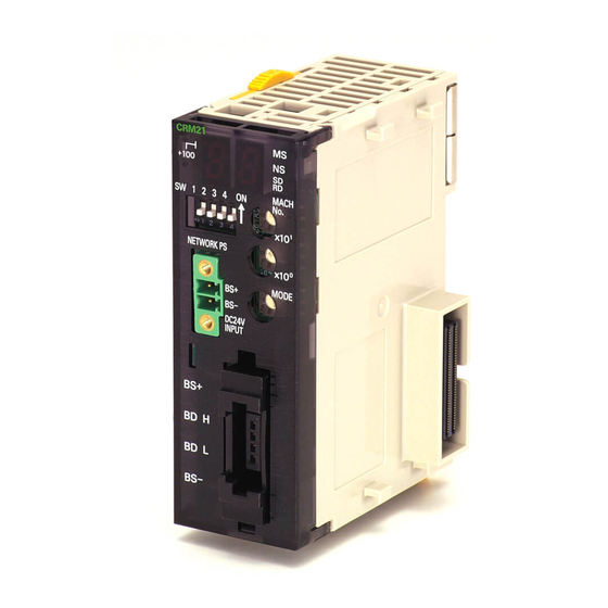
2 CompoNet Master Unit 2-1-2 Component Names and Functions Display Section Shows the Master Unit status and Slave Unit communications status. · Indicators CRM21 Four LED indicators: +100 MS (green/red), NS (green/red), SD (yellow), and RD (yellow) · Seven-segment Display MACH Displays the communications status, error code, etc. -
Page 82: Display Section
2 CompoNet Master Unit 2-1-3 Display Section Communications Indicators The following LED indicators are provided for communications. MS (Module Status): Shows the status of the node itself. (Two colors: green and red) NS (Network Status): Shows the status of communications. (Two colors: green and red) SD (Send Data): Shows Master Unit transmission status. - Page 83 2 CompoNet Master Unit Seven-segment Display • The seven-segment display shows the baud rate during normal transmission. It lights while remote I/O communications are in progress and flashes while they are stopped. • When a communications error occurs, the following information is displayed in order: Error code (2 digits hexadecimal) - Type of Slave Unit at error node - Node address (2 digits decimal).
- Page 84 2 CompoNet Master Unit Display Status Display Actual display Contents contents Error Initialization error Error code The error code is displayed in hexadecimal (lit). Communications The error code, The error code (2 digits hexadecimal), Slave Unit type, and applicable error Slave Unit type, node address (1-bit dot notation for the 100 position for 3-digit decimal) and applicable...
-
Page 85: Switch Settings
2 CompoNet Master Unit 2-1-4 Switch Settings Unit Number Switches (MACH No.) Use these switches to set the Special I/O Unit unit number (two decimal rotary switches (0 to 95)). The setting is read when the power supply is turned ON to the Controller. Communications mode number Setting range 00 to 94... - Page 86 2 CompoNet Master Unit Communications Mode Number Switch (MODE) Use this switch to set the communications mode number of the Master Unit (one decimal rotary switch (0 to 3 or 8)). The setting is read when the power supply is turned ON to the Controller. Number of unit Commu- Connectable node...
- Page 87 2 CompoNet Master Unit Precautions for Safe Use Always set the same communications mode number on the rotary switch on the front of the Com- poNet Master Unit and for the communications mode number setting when you register the Unit on the Sysmac Studio (MODE@ in the Unit Name).
-
Page 88: Terminal Arrangement
2 CompoNet Master Unit 2-1-5 Terminal Arrangement Communications Power Supply Connector This connector supplies communications power to Slave Units and Repeater Units connected to the trunk line. BS+ (communications power supply positive side) BS− (communications power supply negative side) Note This connector does not supply power to the Master Unit. Communications Connector BS+ (communications power supply positive side) BDH (communications data high side) - Page 89 Wiring Configurations 3-1 Wiring Formations ..........3-2 3-2 CompoNet Network Wiring .
-
Page 90: Wiring Formations
3 Wiring Configurations Wiring Formations A CompoNet network can take two wiring formations: Trunk line-Branch line and Unrestricted Wiring. There are restrictions on the number of branches and the number of Units that can be connected. Trunk Line-Branch Line Formation With this wiring formation, the trunk line is differentiated from branch lines. - Page 91 3 Wiring Configurations The following table shows the conditions and restrictions for each formation. Wiring formation Item Trunk-Branch formation Unrestricted wiring formation Master Unit location At an end of a network Anywhere in a network (not necessar- ily at an end) Maximum number of Slave Units 1 or 3 depending on the cable type No restrictions...
-
Page 92: Componet Network Wiring
3 Wiring Configurations CompoNet Network Wiring A CompoNet Network requires wiring of following lines. • Two communications signal lines: BDH (communications data high) and BDL (communications data low) • Two communications power supply lines (for both communications power and Slave Unit internal cir- cuit power) Terminals are BS+ (positive terminal of communications power supply) and BS−... - Page 93 3 Wiring Configurations Multidrop connections can also be used to connect the Slave Units in parallel. Master Unit or Repeater Unit Terminating Resistor (121 Ω) BS− Commu- nications Open Type Connector Communications Communications Slave Unit Slave Unit Slave Unit BS− BS−...
-
Page 94: Round Cable Ii
3 Wiring Configurations 3-2-2 Round Cable II • The two communications signal lines and the two communications power supply lines are connected in parallel between the Master Unit or Repeater Unit and multiple Slave Units. • A DCN4-TB4 Open Type Connector is used to connect the communications cable between the Mas- ter Unit or a Repeater Unit and a Slave Unit. -
Page 95: Flat Cable I Or Flat Cable Ii
3 Wiring Configurations 3-2-3 Flat Cable I or Flat Cable II • The two communications signal lines and the two communications power supply lines are connected to the Master Unit, Repeater Units, and Slave Units using Flat Cable. • Connect the communications power supply (24 VDC) to the communications power supply connector for the Master Unit or Repeater Unit. -
Page 96: Cable Types
3 Wiring Configurations 3-2-4 Cable Types Cable Types The four types of cable listed in the following table can be used as the communications cable for a Com- poNet Network. Do not use any other cables. Conductors BS+ (com- BS- (com- munica- munica- Communi-... - Page 97 3 Wiring Configurations Round Cable I Use a commercially available VCTF cable with two 0.75-mm conductors (JIS C3306) that meets CompoNet specifications. Ask the cable manufacturer for products applicable to CompoNet. White: BDH Blue or black: BDL Round Cable II Use a commercially available VCTF cable with four 0.75-mm conductors (JIS C3306) that meets CompoNet specifications.
- Page 98 3 Wiring Configurations DCA5-4F10 Flat Cable II Red: BS+ White: BDH Blue: BDL Black: BS− Conductor Insulation Nominal cross-sec- Allowable current Application color tion BS+ (communications power 5 max. 0.75 mm supply positive side) White BDH (signal high) 0.5 mm Blue BDL (signal low) 0.5 mm...
- Page 99 3 Wiring Configurations Selecting Cable Types Refer to Types of Cables on page 1-28 in 1-6-1 Design, and select applicable cables. Using Different Cable Types All cables downstream from the Master Unit must be the same type. That means the same type of cable must be used for the trunk line and their branch lines;...
-
Page 100: Connection Methods
3 Wiring Configurations 3-2-5 Connection Methods Round Cable I or Round Cable II Cable branches Slave Unit/Repeater Master Unit connections Unit connections T-branch connections Multidrop connections Open Type Connector Open Type Connector Relay terminal block (com- Open Type Connector mercially available product) Open Type Trunk line, Branch line or... -
Page 101: Node Connection Methods
3 Wiring Configurations 3-2-6 Node Connection Methods Nodes are connected to the CompoNet Network using the methods described in this section. Master Unit Connections Except in unrestricted wiring formations, the Master Unit must always be connected on one end of the trunk line. -
Page 102: Branching A Communications Cable
3 Wiring Configurations 3-2-7 Branching a Communications Cable There are two ways to branch the trunk line, sub-trunk lines, and branch lines: T-branching and multi- drop connections. T-branching Round Cable I or Round Cable II (with a Commercially Available Relay Terminal Block) Use a commercially available relay terminal block, and connect the cable wires to the block. - Page 103 3 Wiring Configurations • Example for Flat Cable II Attach a DCN5-BR4 Flat Connector Plug to a DCN5-TR4 Flat Connector Socket. DCN5-TR4 Flat DCN5-BR4 Flat Connector Socket Connector Plug Slave Unit Note The same type of cable must be used for both the trunk line and the branch line. Multidrop Connections Round Cable I or Round Cable II (with an Open Type Connector) DCN4-TB4 Open Type...
-
Page 104: Extending The Cable Length
3 Wiring Configurations 3-2-8 Extending the Cable Length Flat Connectors can be used to extend the cables for the trunk line, sub-trunk lines, branch lines, and sub-branch lines to up to ten levels. The maximum distance that the cables can be extended is restricted by the maximum trunk line length. -
Page 105: Connection Locations For Terminating Resistors
3 Wiring Configurations 3-2-9 Connection Locations for Terminating Resistors Terminating Resistors must always be connected to the trunk line and each sub-trunk line on the oppo- site end from the Master Unit or Repeater Unit. Note Do not connect a Terminating Resistor on the end of the Network with the Master Unit. When the trunk line or sub-trunk line is branched, the Terminating Resistor is connected to the end of the branch line farthest from the Master Unit or Repeater Unit. - Page 106 3 Wiring Configurations Connecting Terminating Resistors There are three methods that can be used to connect Terminating Resistor. Method 1: Connect a Flat Connector Socket to the trunk line or sub-trunk line and then connect a Ter- minating Resistor to the Connector. Flat Cable I Flat Cable II Flat Connector...
-
Page 107: Connection Locations For Communications Power Supply
3 Wiring Configurations 3-2-10 Connection Locations for Communications Power Supply Connect the communications power supply as shown in the following diagrams. Round Cable II, Flat Cable I, or Flat Cable II Example for Flat Cable I or II Communica- tions power supply, 24 VDC Master Unit Com-... - Page 108 3 Wiring Configurations 3-20 CJ-series CompoNet Master Unit Operation Manual for NJ-series CPU Unit (Cat. No. W493)
-
Page 109: Installation And Wiring
Installation and Wiring 4-1 Installation ........... 4-2 4-1-1 Tools Required for Installation and Wiring . -
Page 110: Installation
4 Installation and Wiring Installation 4-1-1 Tools Required for Installation and Wiring The following tools are required to install, wire, and set the Units. • Phillips screwdrivers: M3 and M4: To install and wire I/O for the Master Unit, Slave Units, and Repeater Units. -
Page 111: Installing The Master Unit
4 Installation and Wiring 4-1-3 Installing the Master Unit The Master Unit is connected to the CPU Unit. It is connected to the CPU Unit in the same way as other Units. System Configuration Precautions You can connect the Master Unit to the CPU Rack or an Expansion Rack as long as there are no more than 10 Units on one Rack. - Page 112 4 Installation and Wiring Unit Handling Precautions • Always turn OFF the power supply to the Controller before you mount or dismount a Unit or connect or disconnect cables. • To prevent noise from affecting the system, place all wires connected to the Unit ports in ducts, and use separate ducts from those used for high-voltage and high-power lines.
-
Page 113: Connecting Cables
4 Installation and Wiring Connecting Cables 4-2-1 Overview This section provides an outline of connecting a CompoNet Network using Round Cable I and Flat Cable I cables. Refer to SECTION 3 Wiring Configurations for information on the configuration. Refer to 4-4 Power Supply Wiring for information on supplying communications power. - Page 114 4 Installation and Wiring Flat Cable I T-branching Note T-branches and multidrop connections can be used together. DCN4-BR4 Flat Connector Plug DCN4-TR4 Flat Connector Socket DCN4-TR4 Flat Connector DCN4-TR4 Flat Connector Socket T-branch Socket T-branch DCN4-BR4 Flat Connector Plug DCN4-TM4 Terminating DCN4-BR4 Flat Connector Resistor Plug...
-
Page 115: Connecting To Units
4 Installation and Wiring 4-2-2 Connecting to Units Connecting the Trunk Line to the Master Unit Round Cable I or II A DCN4-TB4 Open Type Connector is used. Orient the Open Type Connector so that surface with the open terminals is facing to the left and press in the Open Type Connector until it clicks into place. - Page 116 4 Installation and Wiring Flat Cable I A DCN4-BR4 Flat Connector Plug is connected to the communications connector on the Master Unit. Refer to 4-3 Preparing and Mounting Flat Connectors. Orient the Connector so that the line colors are indicated (red, white, blue, and black) is facing to the left and press in the Connector until it clicks into place.
- Page 117 4 Installation and Wiring Flat Cable II A DCN5-BR4 Flat Connector Plug is connected to the communications connector on the Master Unit. Refer to 4-3 Preparing and Mounting Flat Connectors. Orient the Connector so that the white line on the cable is facing to the left and press in the Connec- tor until it clicks into place.
-
Page 118: Branching A Communications Cable
4 Installation and Wiring 4-2-3 Branching a Communications Cable There are two ways to branch the trunk line, sub-trunk lines, and branch lines: T-branches and multi- drop connections. T-branching Round Cable I or II Use a commercially available relay terminal block, and connect the cable wires to the block. Example for Round Cable I Relay terminal block Slave Unit... - Page 119 4 Installation and Wiring Flat Cable II Attach a DCN5-BR4 Flat Connector Plug to a DCN5-TR4 Flat Connector Socket which has already been mounted to the communications cable. DCN5-BR4 Flat DCN5-TR4 Flat Connector Plug Connector Socket Slave Unit • Mounting Procedure Hold the Connector Plug with the side with white line facing down, and push the Connector Plug inward until it clicks into place.
- Page 120 4 Installation and Wiring (2) Open the terminal cover of the Open Type Connector. Connect the cable wires to the BDH terminal (communications data high) and the BDL terminal (communications data low). If a Round Cable II cable is being used, connect the other wires to the BS+ terminal (positive terminal of communications power supply) and the BS−...
-
Page 121: Extending A Communications Cable
4 Installation and Wiring Flat Cable II Multidrop connections are not supported. 4-2-4 Extending a Communications Cable Flat Connectors can be used to extend cables for the trunk line, sub-trunk lines, branch lines, and sub- branch lines to maximum ten levels. The maximum trunk line length is the upper limit of extension of each type of cable. -
Page 122: Connecting Terminating Resistors
4 Installation and Wiring 4-2-5 Connecting Terminating Resistors A Terminating Resistor must always be connected to the trunk line and each sub-trunk line on its oppo- site end from the Master Unit or a Repeater Unit. Round Cable I The cable wires are connected to a DRS1-T Terminating Resistor. Round Cable I Terminating Resistor •... - Page 123 4 Installation and Wiring Flat Cable I A DCN4-TR4 Flat Connector Socket is mounted at the end of the communications cable. Then a DCN4-TM4 Terminating Resistor is attached to the Socket. Flat Connector Socket Terminating Resistor • Mounting Procedure Press the Terminating Resistor into the Socket until it clicks into place. Note To remove a Terminating Resistor which has been attached, hold the latches on both sides of the Resistor, and pull it out.
-
Page 124: Preparing And Mounting Flat Connectors
4 Installation and Wiring Preparing and Mounting Flat Connectors When you connect a Terminating Resistor to a Round Cable II cable, connect a Flat Cable I or II cable to the Unit, or when you branch or extend the line, you must prepare a Flat Connector and mount it on the cable. -
Page 125: Round Cable Ii
4 Installation and Wiring Name Appearance Model Application Flat Connector DCN5-BR4 Used as a set with the DCN5-TR4 Flat Connector Socket in Plug the following applications: • Extending the trunk line or sub-trunk lines. • T-branching branch lines from the trunk line or sub-trunk lines. - Page 126 4 Installation and Wiring Preparing the Cable At the tip of cable, make a cut line perpendicular to the cable length on the sheath, and strip the sheath. White Green or Blue Black Setting the Cable Stopper Set the cable stopper. Close the cover. Secure the hooks. Press down on the cable stopper until it clicks into place.
- Page 127 4 Installation and Wiring Pressure-welding the Connector Use the DWT-A01 Pliers to pressure-weld the connector. (1) Align the center (see arrows) of the connector cover with the center of the pressure- welding block on the DWT-A01 Pliers. Special tool (DWT-A01 Pliers) Connector cover (2) Squeeze firmly on the Pliers until the lock on the connector clicks into place.
-
Page 128: Flat Cable I
4 Installation and Wiring 4-3-2 Flat Cable I Preparing and Mounting DCN4-TR4 Flat Connector Sockets • Component Names Cover Housing Cable labels (Black, blue/green, white, and red) Cable confirmation slot Black Cutting the Cable This step is required only for extending the cable or connecting a Terminating Resistor. Cut the cable perpendicular to its length. - Page 129 4 Installation and Wiring Mounting the Cable • T-branching (1) Confirm that the cable colors match the cable labels, and then place the cable in the cover. (2) Close the cover to sandwich the cable and secure the hook. • Extending or Connecting a Terminating Resistor Insert the cable tip all the way into the cable stopper in the cover.
- Page 130 4 Installation and Wiring Pressure-welding the Connector Use the DWT-A01 Pliers to pressure-weld the connector. (1) Align the center (see arrows) of the connector cover with the center of the pressure- welding block on the DWT-A01 Pliers. Special tool (DWT-A01 Pliers) Connector cover (2) Squeeze firmly on the Pliers until the lock on the connector clicks into place.
- Page 131 4 Installation and Wiring Preparing and Mounting DCN4-BR4 Flat Connector Plugs • Component Names Cable labels (Flat cable: black, blue/green, white, and red) Black Lock lever Cutting the Cable Cut the cable perpendicular to the length. To prevent short-circuits, use a sharp cutting tool such as nipper. Confirm there is no remaining wire coming out.
- Page 132 4 Installation and Wiring (2) Squeeze firmly on the Pliers until the lock on the connector clicks into place. Precautions for Correct Use Precautions for Correct Use • Do not pressure-weld the connector cover at the edges. • Do not pressure-weld the connector cover at the back of the pressure-welding block. •...
-
Page 133: Flat Cable Ii
4 Installation and Wiring Attaching the Housing (1) Confirm the colors again, and temporarily secure the housing to the cover. Pressure-welding the Connector Use the DWT-A01 Pliers to pressure-weld the connector. (1) Align the center (see arrows) of the connector cover with the center of the pressure- welding block on the DWT-A01 Pliers. - Page 134 4 Installation and Wiring Setting the Cable Stopper This step is required only for extending the cable or connecting a Terminating Resistor. For these purposes, the cable can end in the connector. Place the cable stopper in advance. Put the cable in the cover. Position the cable so that the cable tip touches the stopper. Cable stopper Attaching the Cable (1) Hold the cable with the white line facing up and near the cover opening.
- Page 135 4 Installation and Wiring (2) Hold the cable to prevent dislocation and close the cover. Note For extension or to connect a Terminating Resistor, make sure the cable tip is inserted to the cable stopper and will not come out. Pressure-welding the Connector The connector is pressure-welded using the DWT-A02 Pliers.
- Page 136 4 Installation and Wiring Preparing and Mounting DCN5-BR4 Flat Connector Plugs • Component Names Cover Cutting the Cable Cut the cable perpendicular to the length. To prevent short-circuits, use a sharp cutting tool such as nipper. Confirm there is no remaining wire coming out.
- Page 137 4 Installation and Wiring Pressure-welding the connector The connector is pressure-welded using the DWT-A02 Pliers. (1) Align the center (see arrows) of the connector cover with the center of the pressure- welding block on the DWT-A02 Pliers. Connector position reference surfaces Special tool (DWT-A02 Pliers) Connector cover (2) Squeeze firmly on the Pliers until the lock on the connector clicks into place.
-
Page 138: Power Supply Wiring
4 Installation and Wiring Power Supply Wiring The following power supplies are required to operate the CompoNet Network. • Communications power supply: Used for communications with individual Units and for internal circuit operations of Units. • I/O power supply: Used for I/O operations for Units with external I/O. The method for supplying communications power and I/O power depends on the types of cable and Slave Unit that are used. - Page 139 4 Installation and Wiring Round Cable II, Flat Cable I, or Flat Cable II • Communications Power Power is supplied through the communications power supply connector on the Master Unit. Power is also supplied through the downstream port of the communications power supply connector on each Repeater Unit.
-
Page 140: Connecting The Communications Power Supply
4-4-1 Connecting the Communications Power Supply The communications power supply must meet the following specifications. Commercially available power supply units can be used. An OMRON S82-series Power Supply Unit is recommended to sup- ply communications power to a CompoNet network. -
Page 141: Connecting The Communications Power Supply
4 Installation and Wiring + (Actual load current of an actuator x Number of actuators) (3) I/O Units Current consumption of the communications power supply = Current consumption of a Bit Slave for communications + (Input current of a Bit Slave x Number of used channels) + (Current consumption of a sensor x Number of used sensors) + (Actual load current of an actuator x Number of actuators) Use a power source with sufficient capacity, allowing for inrush current at startup. -
Page 142: Current Consumption Of A Slave Unit Or A Repeater Unit
4 Installation and Wiring 4-4-3 Current Consumption of a Slave Unit or a Repeater Unit Refer to the CRT1-series CompoNet Slave Units and Repeater Unit Operation Manual (Cat. No. W457- E1). 4-4-4 Communications Power Supply Wiring Example Round Cable I When Round Cable I cables are used, the communications power cannot be supplied through the com- munications cables. - Page 143 4 Installation and Wiring With Repeater Units Master Unit *1: When complying with UL standards, install a device to limit the current between the external power supply and the Unit to 4 A Round Cable I or less for the communications power supply. Communications Overcurrent power supply...
- Page 144 4 Installation and Wiring Round Cable II, Flat Cable I, or Flat Cable II The communications power to Slave Units is supplied through a Round Cable II, Flat Cable I or Flat Cable II cable. Therefore there is no need to provide a communications power supply for Slave Units separately.
- Page 145 4 Installation and Wiring With Repeater Units Communications power supply connector Overcurrent Communications protection (*1) power supply (current limit: 4 A) Master Unit Power *1: When complying with UL standards, install a supply device to limit the current between the external power supply and the Unit to 4 A or less for the communications power supply.
- Page 146 4 Installation and Wiring Restrictions The following restrictions apply when supplying communications power through a Round Cable II, Flat Cable I, or Flat Cable II cable. • The communications power supply can be connected at only one location for the trunk line and one location each for the sub-trunk lines.
- Page 147 4 Installation and Wiring • Use separate power supplies each for the Master Unit trunk line and for the upstream and down- stream trunk lines from a Repeater Unit. Power Can Be Supplied Master Unit or Repeater Unit Communications power supply Trunk line or Round Cable II, Flat Cable I, or Flat Cable II sub-trunk line...
- Page 148 4 Installation and Wiring Using Round Cable I with Round Cable II, Flat Cable I, or Flat Cable II In a CompoNet network, Round Cable I cables can be installed under the same Master Unit as Round Cables II, Flat Cable I, or Flat Cable II cables as long as they are separated by a Repeater Unit. Master Unit Round cable I Downstream port communications power supply connector...
-
Page 149: Precaution In Supplying Power To Slave Units
4 Installation and Wiring 4-4-5 Precaution in Supplying Power to Slave Units When supplying communications power and I/O power, the allowable currents of cables and connec- tions, the voltage drop, and the capacity and location of power supplies must be considered. Allowable Current Restrictions Do not allow the total current consumption of all Slave Units to exceed the allowable current of the com- munications cables and connectors. - Page 150 4 Installation and Wiring Voltage Drop Cable Voltage Drop The voltage drop must be considered so that the power supply voltage at the Slave Unit that is the farthest from the power supply will still be within the allowable power supply range. The voltage drop is expressed by the following formula.
-
Page 151: Precautions On Locating The I/O Power Supply
4 Installation and Wiring 4-4-6 Precautions on Locating the I/O Power Supply When building a system, the supply methods for communications power and I/O power must be consid- ered. Not only hardware, such as selecting the power supplies and cables based on allowable currents and voltage drop, be considered, but also system operation for power supply errors, costs, and other software issues must be considered when studying power supply methods. -
Page 152: Other Precautions
4 Installation and Wiring 4-4-7 Other Precautions Power Supply Errors The location of power supplies and the grouping of Slave Units should be considered based on whether the overall system is to be stopped when a power supply error occurs. If it is necessary to prevent the overall system from stopping to ensure system safety, consider placing power supplies in more than one location and consider the way Slave Units should be grouped when supplying power. - Page 153 Remote I/O Communications 5-1 Exchanging Data with the CPU Unit ....... 5-2 5-1-1 Exchanging Data between the CPU Unit and the CompoNet Master Unit .
-
Page 154: Remote I/O Communications
5 Remote I/O Communications Exchanging Data with the CPU Unit Communications for sharing data can be continuously performed between the CPU Unit and the Com- poNet Master Unit, and between the CompoNet Master Unit and Slave Units. This is called remote I/O communications. - Page 155 5 Remote I/O Communications CompoNet Master Unit NJ-series CPU Unit User program For communications I/O refreshing I/O ports mode number 0 to 3 OUT Data Device variables OUT Data for the CJ-series IN Data IN Data Unit specifications Connect Flags Connect Flags and and Communica- Communication Error Flags...
- Page 156 5 Remote I/O Communications Device Variables for the CJ-series Unit Device variables for the CJ-series Unit are variables with AT specifications to the I/O ports that are described below. Device variables for CJ-series Units are used in the user program to access the Com- poNet Master Unit and other Configuration Units.
-
Page 157: Access Methods From User Program
5 Remote I/O Communications 5-1-2 Access Methods from User Program Use variables to access the I/O ports from the user program. Differences in Access Methods for Each Type of Data The following table shows how different types of data are exchanged between the CPU Unit and the CompoNet Master Unit depending on the communications mode. - Page 158 5 Remote I/O Communications Access with User-defined Variables (Communications Mode Number If you set communications mode number 8 (Software Setting Mode), user-defined variables are required to access the I/O data, Connect Flags, and Communication Error Flags of the CompoNet Mas- ter Unit.
-
Page 159: I/O Ports For The Componet Master Unit
5 Remote I/O Communications 5-1-3 I/O Ports for the CompoNet Master Unit With an NJ-series CPU Unit, I/O ports are defined in advance for the following data of the CompoNet Master Unit. (1) I/O data (except for communications mode number 8) (2) Connect Flags and Communication Error Flags (except for communications mode number 8) (3) Status information... - Page 160 5 Remote I/O Communications Word Slave Units The following assignments are made when the node address of the Word Slave Unit is set to nn (00 to 15). • Sixteen inputs are assigned to the following I/O ports: InDatnn_00 to InDatnn_15. The next 16 inputs are assigned to the following I/O ports: InDatnn+1_00 to InDatnn+1_15.
- Page 161 5 Remote I/O Communications 1. Sixteen-point Input Slave Unit with Node Address 0: The 16 inputs are assigned to InDat00_00 to InDat00_15 (bits 00 to 15) of InDat00 (WORD IN Data00). 2. Twenty-four-point Input Slave Unit with Node Address 1: The first 16 inputs are assigned to InDat01_00 to InDat01_15 (bits 00 to 15) of InDat01 (WORD IN Data01).
- Page 162 5 Remote I/O Communications Bit Slave Units The following assignments are made when the node address of the Bit Slave Unit is set to mm (00 to 63). • Two inputs are assigned to the following I/O ports: BitInDatmm_00 and BitInDatmm_01. •...
- Page 163 5 Remote I/O Communications Connect Flags and Communication Error Flags (Communications Mode Number 0 to 3) These flags indicate if the Slave Units are normally participating in the network. They are assigned to I/O ports as shown in the following table. Slave Unit of Connect I/O port (nn = Node Type of data...
- Page 164 5 Remote I/O Communications The status information is assigned to I/O ports as shown in the following table. Type of data Data name I/O ports Status Status UnitSta Communications Error Flag SlavCommErr Registration Table Verification Error Flag RegTblErr Communications Error Communications Stop Flag CommStopSta Slave Unit Duplicated Address Error Flag SlavDupErr...
-
Page 165: Network Status
5 Remote I/O Communications Network Status 5-2-1 Conditions for Starting and Stopping Remote I/O Communications • If the communications power supply to the Slave Units is turned ON, remote I/O communications will start when the power supply is turned ON to the Controller or when the Controller is reset. In Regis- tered Slave Unit Participation Standby Mode, communications will not start until all registered Slave Units are participating in the network. -
Page 166: Confirming Normal Slave Unit Operation
5 Remote I/O Communications Communications Error Input Data Zero Clear Mode Communications Error Input Data Zero Clear Mode can be set from the CX-Integrator for communica- tions errors. If a communications error occurs for a Slave Unit in this mode, all IN Data for that Slave Unit is cleared to zeros. - Page 167 5 Remote I/O Communications Example: This example shows how to combine the Connect Flag and Communication Error Flag as the condition for using the input value in bit 05 of the Word Input Slave Unit with node address 08 only when the Slave Unit is operating normally. Communication Normal operation Error Flag...
- Page 168 5 Remote I/O Communications Registration Tables Overview Registration Tables are used to register Slave Units that are intended to participate at particular node addresses (along with the models corresponding to the node addresses) to enable verifying that they actually are participating. At the same time, they prevent unregistered Slave Units and Slave Units of the wrong models or with the wrong node addresses from participating in the net- work.
- Page 169 5 Remote I/O Communications rate other than 93.75 kbps, and 30 s for 93.75 kbps. ) At the same time, the NS indicator on the front of the Master Unit will flash red and the seven-segment display will show d5. How- ever, if the applicable Slave Unit subsequently starts participating, *_RegTblErr (Registration Table Verification Error Flag) will change to FALSE and the error display will be cleared.
- Page 170 5 Remote I/O Communications The Registration Table is then enabled by turning ON the power supply with SW4 (REGS) on the Master Unit set to ON. (The Registration Table is read when the power supply is turned ON.) *_RegTblSta (Registration Table Mode Flag) in *_UnitSta (Status) will change to TRUE (Registration Table Enable Mode).
- Page 171 5 Remote I/O Communications Slave Unit Duplicated Address Error In any of the following cases, a Slave Unit duplicated address error will occur and *_SlavDupErr (Slave Unit Duplicated Address Error Flag) in *_UnitSta (Status) will change to TRUE for the Slave Unit that joined the network last.
-
Page 172: Device Variables For The Cj-Series Unit
5 Remote I/O Communications Device Variables for the CJ-series Unit Device variables for the CJ-series Unit are used with AT specifications to I/O ports to access the I/O data in the CompoNet Master Unit. This section describes the functions of the individual device vari- ables for the CJ-series Unit. -
Page 173: I/O Data
5 Remote I/O Communications 5-3-2 I/O Data Word Slave Units nn = Node address RW: Read/write, R: Read-only Device variables Communications mode number for the CJ-series Data type Name Description Unit *_OutDat00 to WORD WORD OUT WORD OUT *_OutDatnn (n = 07) (n=15) (n=31) (n=15) -
Page 174: Connect Flags And Communication Error Flags
5 Remote I/O Communications Bit Slave Units mm = Bit node address RW: Read/write, R: Read-only Communications mode number Device variables for Data type Name Description the CJ-series Unit *_BitOutDat00_00, BOOL BitOUT Bits 00 and 01 *_BitOutDat00_01 (m=63) Data00 of BitOUT Data Bit00, Bit01 for bit node address 00... - Page 175 5 Remote I/O Communications Device variables Communications mode number for the CJ-series Data type Name Description Unit *_OutCnctNdSta BYTE WORD OUT Bits 0 to 7: 16_23 Connect Node Flag16_23 addresses 16 to 23 *_OutCnctNdSta BOOL WORD OUT Connect Flags Connect for node Flag16 addresses 16...
- Page 176 5 Remote I/O Communications Device variables Communications mode number for the CJ-series Data type Name Description Unit *_InCnctNdSta BYTE WORD IN Bits 0 to 7: 16_23 Connect Node Flag16_23 addresses 16 to 23 *_InCnctNdSta16 BOOL WORD IN Connect Flags Connect for node Flag16 addresses 16...
- Page 177 5 Remote I/O Communications Device variables Communications mode number for the CJ-series Data type Name Description Unit *_OutErrNdSta BYTE WORD OUT Bits 0 to 7: 16_23 Communi- Node cation Error addresses 16 Flag16_23 to 23 *_OutErrNdSta16 BOOL WORD OUT WORD OUT Communi- Communica- cation Error...
- Page 178 5 Remote I/O Communications Device variables Communications mode number Data for the CJ-series Name Description type Unit *_InErrNdSta BYTE WORD IN Bits 0 to 7: Node 16_23 Communica- addresses 16 to 23 tion Error Flag16_23 *_InErrNdSta BOOL WORD IN WORD IN Communi- Communica- cation Error Flags for tion Error...
- Page 179 5 Remote I/O Communications Device variables for the Data Name Description CJ-series Unit type *_BitOutCnctNdSta32_39 BYTE BIT OUT Connect Flag32_39 Bits 0 to 7: Bit node addresses 32 to 39 *_BitOutCnctNdSta32 BOOL BIT OUT Connect Flag32 BIT OUT Connect Flags for bit node addresses 32 to 39 *_BitOutCnctNdSta39 BIT OUT Connect Flag39...
- Page 180 5 Remote I/O Communications Device variables for the Data Name Description CJ-series Unit type *_BitInCnctNdSta48_55 BYTE BIT IN Connect Flag48_55 Bits 0 to 7: Bit node addresses 48 to 55 *_BitInCnctNdSta48 BOOL BIT IN Connect Flag48 BIT IN Connect Flags for bit node addresses 48 to 55 *_BitInCnctNdSta55 BIT IN Connect Flag55...
- Page 181 5 Remote I/O Communications Communication Error Flags for Bit Input Slaves (Communications Mode Number 3) These variables can be used only with the communications mode number is set to 3. Device variables for Data Name Description the CJ-series Unit type *_BitInErrNdSta00_07 BYTE BIT IN Communication Error Flag00_07...
-
Page 182: Status Information: Status (All Communications Modes)
5 Remote I/O Communications 5-3-4 Status Information: Status (All Communications Modes) Device variables for the Data Name Description CJ-series Unit type *_ UnitSta WORD Status The overall status of the network and the status of the Master Unit are stored here. The meanings of individual bits are given below. - Page 183 5 Remote I/O Communications Device variables for the Data Name Description CJ-series Unit type *_SlavCommErr BOOL Communications FALSE: Normal Error Flag TRUE: Error This flag changes to TRUE if a communications error occurs in even one of the applicable Slave Units. *1 All Slave Units are applicable if the power supply was turned ON to the Controller or the Controller was reset with SW4 (REGS) set to OFF on the Master Unit.
- Page 184 5 Remote I/O Communications Device variables for the Data Name Description CJ-series Unit type *_RepeaterCommErr BOOL Repeater Unit FALSE: Normal Communications TRUE: Error Error Flag Note Remote I/O communications will start even if this flag is TRUE. *_RepeaterDupAdrErr BOOL Repeater Unit FALSE: Normal Node Slave Unit TRUE: Error...
-
Page 185: Status Information: Setting (All Communications Modes)
5 Remote I/O Communications Example: In this example, operation is considered normal when all registered Slave Units are par- ticipating, there are no communications errors at any registered Slave Units, and remote I/O communications are operating. Ladder Operation Allowed Flag in Normal operation Registration Table Enabled Mode *_PLCRunSta... -
Page 186: Slave Unit Allocations
5 Remote I/O Communications Slave Unit Allocations This section describes how I/O in the CPU Unit where the CompoNet Master Unit is mounted is allo- cated to the Slave Units. 5-4-1 Overview Slave Unit I/O data, Connect Flags, and Communication Error Flags are assigned to I/O ports in the CPU Unit where the CompoNet Master Unit is mounted. -
Page 187: Types Of Componet Network Node Addresses
5 Remote I/O Communications 5-4-2 Types of CompoNet Network Node Addresses There are the following three types of node address for a CompoNet Network. • Node addresses • Bit node addresses • Repeater node addresses Node Node Abbrevia- Address Unit address Node name address... -
Page 188: I/O Port Allocations For Each Communications Mode Numbers
5 Remote I/O Communications 5-4-3 I/O Port Allocations for Each Communications Mode Numbers The communications mode number is set on the rotary switch on the front of the CompoNet Master Unit and when the CompoNet Master Unit is registered on the Sysmac Studio. You must always set the same communications mode number on the rotary switch on the front panel and in the Sysmac Studio. - Page 189 5 Remote I/O Communications Allowable Slave Unit Node Addresses and Control Points per Master Unit, and Slave Unit I/O Data Allocations and Sizes for Each Communications Mode Words allocated to I/O Port Slave Unit I/O Unit Connect Com- Allowable data allocations Control points num- Flags and...
- Page 190 5 Remote I/O Communications I/O Port Allocation Pattern for each Communications Mode Communications Pattern mode number Device variables for the CJ-series Slave Unit I/O data Unit *_OutDat00 to *_OutDat07 WORD OUT Data (8 words): Word Slave Unit outputs 00 ((*_OutDat00_00 to *_OutDat00_15) to 07 to (*_OutDat07_00 to *_OutDat07_15))
- Page 191 5 Remote I/O Communications Communications Pattern mode number Device variables for the CJ-series Slave Unit I/O data Unit *_OutDat00 to *_OutDat31 WORD OUT Data (32 words): Word Slave Unit outputs ((*_OutDat00_00 to *_OutDat00_15) 00 to 31 to (*_OutDat31_00 to *_OutDat31_15)) *_InDat00 to *_InDat31 WORD IN Data (32 words): Word Slave Unit inputs 00 to ((*_InDat00_00 to *_InDat00_15) to...
- Page 192 5 Remote I/O Communications Communications Pattern mode number Device variables for the CJ-series Slave Unit I/O data Unit *_OutDat00 to *_OutDat15 ((*_OutDat00_00 WORD OUT Data (16 words): Word Slave Unit outputs to *_OutDat00_15) to (*_OutDat15_00 to 00 to 15 *_OutDat15_15)) *_InDat00 to *_InDat15 WORD IN Data (16 words): Word Slave Unit inputs 00 to ((*_InDat00_00 to *_InDat00_15) to...
- Page 193 5 Remote I/O Communications Communications Pattern mode number Device variables for the CJ-series Slave Unit I/O data Unit *_BitInCnctNdSta32_39 Bit Slave Unit inputs 32 to 39 (BYTE) (*_BitInCnctNdSta32 to 39) word) *_BitInCnctNdSta40_47 Bit Slave Unit inputs 40 to 47 (BYTE) (*_BitInCnctNdSta40 to 47) *_BitInCnctNdSta48_55 Bit Slave Unit inputs 48 to 55 (BYTE)
-
Page 194: Details On Allocation Of I/O Ports To Slave Unit I/O Data
5 Remote I/O Communications 5-4-4 Details on Allocation of I/O Ports to Slave Unit I/O Data I/O ports are provided for each node address for CompoNet Network I/O data for Word Slave Unit out- puts, Word Slave Unit inputs, Bit Slave Unit outputs, and Bit Slave Unit inputs. Each node is allocated I/O ports according to the point size of the Slave Unit starting from the node address of the Slave Unit. - Page 195 5 Remote I/O Communications Allocations for WORD OUT Data I/O ports Node Bit 15 Bit 0 address Name Data type OutDat00 WORD WORD OUT Data00 OUTDat00_00 BOOL OUTDat00_15 OutDat01 WORD WORD OUT Data01 OUTDat01_00 BOOL OUTDat01_15 OutDat02 WORD WORD OUT Data02 OUTDat02_00 BOOL OUTDat02_15...
- Page 196 5 Remote I/O Communications I/O ports Node Bit 15 Bit 0 address Name Data type InDat30 WORD WORD IN Data30 InDat30_00 BOOL InDat30_15 InDat31 WORD WORD IN Data31 InDat31_00 BOOL InDat31_15 The following are some examples. • If the Slave Unit with node address 02 has 16 inputs and 16 outputs, it is allocated the InDat02 and OutDat02 I/O ports.
- Page 197 5 Remote I/O Communications Thirty-two-point Output Slave Unit OutDatnn OutDatnn+1 Thirty-two-point Mixed Slave Unit OutDatnn InDatnn Analog Input Slave Units Data to be allocated to the Communications Unit is selected by using one of the following methods, and it is transferred using remote I/O communications. Default Settings With the default settings for an Analog Input Unit, only the analog input values are set as the I/O data.
- Page 198 5 Remote I/O Communications OutDatnn Analog output value for Output 0 OutDatnn+1 Analog output value for Output 1 Data Assignment for Word Slave Unit + Expansion Unit When an Expansion Unit is used, the IN and OUT data of the Expansion Unit is included in the alloca- tion size of the Unit.
- Page 199 5 Remote I/O Communications OutDatnn OutDatnn+1 Sixteen-point Output Slave Unit + Eight-point Expansion Output Unit The I/O ports for two node addresses are allocated: the I/O port for the node address of the Slave Unit (OutDatnn) and the I/O port for the next node address (OutDatnn+1). OutDatnn OutDatnn+1 Unused...
- Page 200 5 Remote I/O Communications Additional Information For Mixed I/O Slave Units, the node address of the Slave Unit is the node address for the IN Data. Therefore, the Connect Flag and Communication Error Flag for the IN Data (InCnctNd- Stann and InErrNdStann) are used. *1 A Word Slave that is a combination of a Basic Unit and Expansion Unit and provides both inputs and outputs, or a CRT1B-MD Bit Slave which provides both inputs and outputs.
-
Page 201: Slave Unit Allocations For Communications Mode Number 8
5 Remote I/O Communications 5-4-5 Slave Unit Allocations for Communications Mode Number 8 When using communications mode 8, I/O ports are not used. I/O data for the CompoNet Master Unit is assigned in software settings directly to any locations in the memory used for CJ-series Units (any addresses in the CIO, WR, HR, or DM Area). - Page 202 5 Remote I/O Communications Memory Allocations for Communications Mode Number 8 Memory is allocated as shown below to the WORD OUT Data, WORD IN Data, BitOUT Data, BitIN Data, Connect Flags, and Communication Error Flags according to the software settings. Word Slave Unit Output Area (OUT) Word address Bit 15...
- Page 203 5 Remote I/O Communications Word Slave Connect Flags and Communication Error Flags (Status) Word address Bit 15 Bit 0 The first Communication Error Flags: OUT0 to OUT7 Connect Flags: OUT0 to OUT7 The number address is Connect Flags: IN0 to IN7 Communication Error Flags: IN0 to IN7 of nodes N specified.
-
Page 204: Remote I/O Communications Performance
5 Remote I/O Communications Remote I/O Communications Performance This section describes the performance of remote I/O communications in a CompoNet Network. 5-5-1 I/O Response Time This section describes the minimum and maximum I/O response times in a CompoNet Network. The I/O response time is the time that is required for an input signal from an Input Slave Unit to be pro- cessed by the CPU Unit where the Master Unit is mounted until it is output to an Output Slave Unit. - Page 205 5 Remote I/O Communications • TNetCyc: Communications Cycle Time Baud rate Maximum I/O 4.0 Mbps 3.0 Mbps 1.5 Mbps 93.75 kbps Communica- tions mode Communications mode 0 128 word inputs, 128 0.9 ms 0.9 ms 1.5 ms 19.8 ms word outputs (0.7 ms) (0.7 ms) (1.1 ms)
- Page 206 5 Remote I/O Communications • TNetCycInt: Interrupt processing time Baud rate 4.0 Mbps 3.0 Mbps 1.5 Mbps 93.75 kbps Communications mode Communications mode 0 0.40 ms 0.45 ms 0.60 ms 6.90 ms Communications mode 1 0.42 ms 0.48 ms 0.68 ms 6.98 ms Communications mode 2 0.48 ms...
- Page 207 5 Remote I/O Communications • TCrmOutMax: Maximum output processing time at Master Unit Communications Communica- Communica- Communica- Communica- mode 0 tions mode 1 tions mode 2 tions mode 3 tions mode 8 0.086 ms 0.090 ms 0.098 ms 0.094 ms 0.082 ms + J ( *1 Communications Mode 8 J = (Number of Word Output Slave Units ×...
- Page 208 5 Remote I/O Communications Additional time per Word Output Slave Unit and Additional time per 8 Bit Output Slave Units Baud rate 4.0 Mbps 3.0 Mbps 1.5 Mbps 93.75 kbps Slave Unit type 4.0 µs 5.312 µs 10.656 µs 171.104 µs Word Output 4.0 µs 5.312 µs...
- Page 209 5 Remote I/O Communications Bit Slave Units Tcpu Tcpu CPU Unit processing TNetCycInt TCrmInMax TCrmOutMax Master Unit processing TNetBitIn TNetCyc TNetCyc TNetCyc TNetCyc Communications cycle TNetOut TOUT Slave Unit processing Maximum I/O response time Formula for the Maximum I/O Response Time for a Bit Slave Unit TIN + TNetCyc ×...
- Page 210 5 Remote I/O Communications • TCrmInMax: Maximum input processing time at Master Unit Baud rate 4.0 Mbps 3.0 Mbps 1.5 Mbps 93.75 kbps Communications mode Communications mode 3 0.35 ms 0.35 ms 0.39 ms 0.39 ms Communications mode 8 0.25 ms + M ( 0.27 ms + M ( 0.33 ms + M ( 0.35 ms + M (...
- Page 211 5 Remote I/O Communications Minimum I/O Response Time Word Slave Units Tcpu CPU Unit processing TCrmOutMin TCrmOutMin Master Unit processing TNetCyc TNetCyc Communications cycle TNetOut TOUT Slave Unit processing Minimum I/O response time Formula for Word Slave Minimum I/O Response Time TIN + TCrmInMin + Tcpu + TCrmOutMin + TNetOut + TOUT TIN: Input Slave Unit input delay time...
- Page 212 5 Remote I/O Communications • TCrmOutMin: Minimum output processing time at Master Unit Communications Communications Communications Communications Communications mode 0 mode 1 mode 2 mode 3 mode 8 0.05 ms 0.055 ms 0.06 ms 0.06 ms 0.045 ms + N ( *1 Communications Mode 8 N = (Number of Word Output Slave Units ×...
- Page 213 5 Remote I/O Communications Bit Slave Units Tcpu CPU Unit processing TCrmOutMin TNetCycInt TCrmInMin Master Unit processing TNetCyc TNetCyc Communications cycle TNetOut TOUT Slave Unit processing Minimum I/O response time Formula for the Minimum I/O Response Time for a Bit Slave Unit TIN + TNetCycInt + TCrmInMin + Tcpu + TCrmOutMin + TNetOut + TOUT TIN: Input Slave Unit input delay time...
- Page 214 5 Remote I/O Communications Reference Example The following table shows the calculation results for the minimum I/O response time for Bit Slave Units with the maximum number of nodes and a CPU Unit task period of 1 ms. Communi- Bit Slave Unit min. I/O response time (ms) Number of nodes con- cations nected...
-
Page 215: Message Communications
Message Communications 6-1 Message Communications ........6-2 6-1-1 Overview of Message Communications . -
Page 216: Overview Of Message Communications
Remote devices CompoNet Slave Units Features • Explicit messages can be received from OMRON Controllers and they can be sent to CompoNet Slave Units. 6-1-2 Explicit Message Communications Explicit messages that are defined by the CompoNet Network are used to send requests for services to CompoNet Slave Units. -
Page 217: Message Monitoring Timer
6 Message Communications 6-1-4 Message Monitoring Timer The message monitoring timer measures the monitoring time for responses made by the CompoNet Master Unit. It is enabled for explicit message communications. The default setting is for 2 s (2,000 ms). Any time from 1 to 65,535 ms can be set. A longer time must be set if responses from the communications target device (the message transmis- sion destination) are slow. -
Page 218: Sending Explicit Messages
6 Message Communications Sending Explicit Messages You can use a CJ-series CompoNet Master Unit to send explicit messages with a header attached. Explicit messages can be sent to CompoNet Slave Units. Example: NJ-series CPU Unit CJ-series CompoNet Master Unit • Explicit messages can be sent. Explicit message CompoNet Network CompoNet Slave Unit... - Page 219 6 Message Communications When you send an explicit message, specify the Master Unit at the local node as the destination of the command rather than the actual destination (the CompoNet Slave Unit). The actual destination node address is specified in the command data in the SEND EXPLICIT MESSAGE command. Command CPU Unit SendCmd instruction: DstNetAdr input variable...
- Page 220 6 Message Communications SEND EXPLICIT MESSAGE: 28 02 SEND EXPLICIT MESSAGE sends a CompoNet explicit message to the specified class, and receives a response. Command Format 532 bytes max. Command code Class ID Instance ID Service Data Service Code Destination node address Response Format •...
- Page 221 6 Message Communications Parameter Details Destination Node Address (Command) This parameter specifies the node address of destination Slave Unit for an explicit message. Word Input Bit Input Word Output Mixed Word Bit Output Mixed Bit Repeater Slave Unit Slave Unit Slave Unit Slave Unit Unit...
- Page 222 6 Message Communications End code Description 1004 hex The command format is not suitable. 1005 hex There is a header error. (The destination address setting is illegal.) 110B hex The response exceeded the maximum response length. 2211 hex The Unit is busy. (The memory required for internal transmission processing cannot be reserved.) 2609 hex The required settings have not been made.
- Page 223 6 Message Communications • When a CompoNet Master Unit receives an explicit message, it automatically returns a response to the message. Service Data • For the command format, specify the lower bytes (L) first followed by the higher bytes (H) for the word (2-byte) data and double-word (4-byte) data in the service data (such as word data and error clear codes).
-
Page 224: Sending Explicit Messages Using Sendcmd Instruction
In the following example, the READ CONTROLLER INFORMATION command (2802) is used to read the vendor code of a Slave Unit from the Master Unit with unit address 16#20. (The vendor code for OMRON is 002F hex.) Command source Destination... - Page 225 Retry = 2 Additional Information If the remote node is an OMRON Special Slave Unit or a CompoNet device from another manu- facturer, set the response monitoring time to at least the value that is set for the message moni- toring timer (default: 2 s).
- Page 226 6 Message Communications Unit Settings Name Setting target Settings Unit Configuration CPU/Expansion Racks Mount CJ1W-CRM21 in slot 0 of the under Controller Configura- CPU Rack. tions and Setup of Sysmac Device name of this unit CompoNet Studio Unit number Unit No. Switch and Unit Con- Unit number 0 figuration and Setup (CPU/Expansion Racks...
- Page 227 6 Message Communications Determining the SendCmd instruction execution completion S endCmd_instance.Done O peratingEnd S endCmd_instance.Error Trigger reception R S_instance O perating T rigger _ Port_isAvailable S et O peratingEnd R eset1 Communications parameters settings O perating InDNetAdr.NetNo:=USINT#0; Network address settings InDNetAdr.NodeNo:=USINT#0;...
- Page 228 6 Message Communications 6-14 CJ-series CompoNet Master Unit Operation Manual for NJ-series CPU Unit (Cat. No. W493)
-
Page 229: Troubleshooting
Troubleshooting 7-1 Handling Errors ..........7-2 7-1-1 CompoNet Master Unit Errors . -
Page 230: Handling Errors
7 Troubleshooting Handling Errors This section describes how to handle CompoNet Network errors that may occur. 7-1-1 CompoNet Master Unit Errors This section describes the meanings of the LED indicators and seven-segment display when errors occur at a CompoNet Master Unit, and it provides countermeasures for handling the errors. Meanings of CompoNet Master Unit Indicators and Procedure for Handling Errors CompoNet Master Units are designed to follow the same basic procedures as CJ-series Special I/O... - Page 231 7 Troubleshooting Initialization Errors 7-seg- Error his- Unit operation after indi- indi- ment Item Probable cause of error Countermeasures tory (hex) error detection cator cator display Correct the unit number, and then restart the Master Unit. Either of the following methods can be used to restart the Master One of the following errors Unit:...
- Page 232 7 Troubleshooting Exception Processing 7-seg- Error his- Unit operation after indi- indi- ment dis- Item Probable cause of error Countermeasures tory (hex) error detection cator cator play After the error is regis- tered in the error his- tory, watchdog timer The Master Unit may have Not lit Unit-related error...
- Page 233 7 Troubleshooting Errors in Remote I/O Communications The following indicator patterns show that an error related to the CompoNet Network has occurred. Errors can basically be identified by the NS indicator flashing red and the seven-segment display show- ing d*. 7-seg- Error Probable cause of...
- Page 234 7 Troubleshooting : Not lit ---: Not applicable yy: Indicates the Slave Unit type, as shown below. Actual display Slave Unit type Word Input Slave Unit (including Mixed I/O Slave Unit) Word Output Slave Unit Bit Input Slave Unit Bit Output Slave Unit Repeater Unit zzz: Node address where the error occurred (2 digits decimal) (Note: The 100s digit is displayed with a dot.) Errors in Memory Access Processing...
-
Page 235: Error History Function
7 Troubleshooting Error History Function The error history registers errors detected by the CompoNet Master Unit, along with the clock times at which they occur. You can monitor the error history from the CX-Integrator. For the procedures to monitor the error history, refer to the CX-Integrator Version 2. Operation Manual (Cat. - Page 236 7 Troubleshooting Error Code and Detailed Information Tables Detailed information Error code Error contents EEPROM (hex) First byte Second byte 0001 CPU Unit watchdog timer error 00 hex 00 hex CPU Unit service monitoring error (Ser- 0002 Monitoring time (ms) vice from the CPU Unit is irregular.) Bit 14: Unit number duplication 0006...
- Page 237 7 Troubleshooting Detailed information Error code Error contents EEPROM (hex) First byte Second byte Packet was discarded because of a 0125 response timeout. Packet was discarded because of a 0300 parameter error. 01 hex: Network parameters 02 hex: Software Setting Table 021A Logic error in setting table...
-
Page 238: Event Logs
7 Troubleshooting Event Logs 7-3-1 Overview of the Event Logs You can use the same methods to manage all of the events that occur on the NJ-series Controller. (The events include errors and information.) You can use the Sysmac Studio or an NS-series PT to confirm current Controller events and the logs of events that have occurred. -
Page 239: Error Table
7 Troubleshooting 7-3-2 Error Table The errors that may occur for this Unit are listed below. The following abbreviations and symbols are used in the event level column. Abbreviation Name Major fault level Partial fault level Minor fault level Observation Info Information Symbol... - Page 240 7 Troubleshooting Level Event code Event name Meaning Assumed cause Reference Obs Info 84600000 hex Communica- A Slave Unit was • Cable lengths (trunk line and page 7-16 tions Error disconnected from branch lines) are unsuitable. the network. • A cable is disconnected or loose.
- Page 241 7 Troubleshooting 7-3-3 Error Descriptions This section describes the information that is given for individual errors. Controller Error Descriptions The items that are used to describe individual errors (events) are described in the following copy of an error table. Event name Gives the name of the error.
-
Page 242: Error Descriptions
7 Troubleshooting Error Descriptions Event name Registration Table Verification Error Event code 349C 0000 hex Meaning An inconsistency was found when verifying the slave registration table. Source PLC Function Module Source details CJ-series Unit Detection At power ON timing Error attributes Level Minor fault Recovery... - Page 243 7 Troubleshooting Event name Repeater Unit Node Duplicated Address Error Event code 349E0000 hex Meaning The node address of the Repeater Unit is also set for another node. Source PLC Function Module Source details CJ-series Unit Detection During Compo- timing Net communica- tions Error attributes...
- Page 244 7 Troubleshooting Event name Communications Error Event code 8460 0000 hex Meaning A Slave Unit was disconnected from the network. Source PLC Function Module Source details CJ-series Unit Detection During Compo- timing Net communica- tions Error attributes Level Minor fault Recovery Error reset Log category...
- Page 245 7 Troubleshooting Event name Repeater Unit Communications Error Event code 84610000 hex Meaning An error occurred in Repeater Unit communications. Source PLC Function Module Source details CJ-series Unit Detection During Compo- timing Net communica- tions Error attributes Level Minor fault Recovery Error reset Log category...
- Page 246 7 Troubleshooting Event name Representative Warning Event code 6498 0000 hex Meaning A warning has occurred in at least one Slave Unit. Source PLC Function Module Source details CJ-series Unit Detection During Compo- timing Net communica- tions Error attributes Level Observation Recovery Log category...
-
Page 247: Appendices
Appendices A-1 Differences in Available Functions Depending on the CPU Unit (NJ or CJ Series) ............A-2 A-1-1 Functional Differences . -
Page 248: Differences In Available Functions Depending On The Cpu Unit (Nj Or Cj Series
Differences in Available Functions Depending on the CPU Unit (NJ or CJ Series) Some of the specifications when a CompoNet Master Unit is connected to a CJ-series CPU Unit are dif- ferent from the specifications when the CompoNet Master Unit is connected to an NJ-series CPU Unit. - Page 249 Appendices Additional Information If you set the same unit number on another Special I/O Unit that is connected to the same CPU Unit, a Duplicate Unit Number major fault level Controller error will occur and the CompoNet Master Unit will not start. If this happens, correct the setting of the unit number and cycle the power supply to the Controller.
- Page 250 Appendices Communications Mode Number 0 CIO n to CIO n+7 (WORD OUT Data) The device variables for CJ-series Units that correspond to bits 00 to 15 in CIO n to CIO n+7 are listed in the following table. CJ-series I/O memory address Device variable for CJ-series Unit in the NJ-series CPU Unit Word address Bit number...
- Page 251 Appendices CJ-series I/O memory address Device variable for CJ-series Unit in the NJ-series CPU Unit Word address Bit number Variable Name CIO n+7 0 to 15 *_ OUTDat07 WORD OUT Data07 *_ OUTDat07_00 WORD OUT Data07 Bit00 *_ OUTDat07_01 WORD OUT Data07 Bit01 *_ OUTDat07_02 WORD OUT Data07 Bit02 *_ OUTDat07_03...
- Page 252 Appendices CJ-series I/O memory address Device variable for CJ-series Unit in the NJ-series CPU Unit Word address Bit number Variable Name CIO n+9 0 to 15 *_ InDat01 WORD IN Data01 *_ InDat01_00 WORD IN Data01 Bit00 *_ InDat01_01 WORD IN Data01 Bit01 *_ InDat01_02 WORD IN Data01 Bit02 *_ InDat01_03...
- Page 253 Appendices CIO n+16 (Status) The device variables for CJ-series Units that correspond to bits 00 to 15 in CIO n+16 are listed in the following table. CJ-series I/O memory address Device variable for CJ-series Unit in the NJ-series CPU Unit Word address Bit number Variable...
- Page 254 Appendices CJ-series I/O memory address Device variable for CJ-series Unit in the NJ-series CPU Unit Word address Bit number Variable Name CIO n+19 0 to 7 *_InCnctNdSta00_07 WORD IN Connect Flag(00 to 07) *_InCnctNdSta00 WORD IN Connect Flag00 *_InCnctNdSta07 WORD IN Connect Flag07 8 to 15 *_InErrNdSta00_07 WORD IN Communication Error Flag(00 to 07)
- Page 255 Appendices CJ-series I/O memory address Device variable for CJ-series Unit in the NJ-series CPU Unit Word address Bit number Variable Name CIO n+15 0 to 15 *_ OUTDat15 WORD OUT Data15 *_ OUTDat15_00 WORD OUT Data15 Bit00 *_ OUTDat15_01 WORD OUT Data15 Bit01 *_ OUTDat15_02 WORD OUT Data15 Bit02 *_ OUTDat15_03...
- Page 256 Appendices CJ-series I/O memory address Device variable for CJ-series Unit in the NJ-series CPU Unit Word address Bit number Variable Name CIO n+17 0 to 15 *_ InDat01 WORD IN Data01 *_ InDat01_00 WORD IN Data01 Bit00 *_ InDat01_01 WORD IN Data01 Bit01 *_ InDat01_02 WORD IN Data01 Bit02 *_ InDat01_03...
- Page 257 Appendices CIO n+32 (Status) The device variables for CJ-series Units that correspond to bits 00 to 15 in CIO n+32 are listed in the following table. CJ-series I/O memory address Device variable for CJ-series Unit in the NJ-series CPU Unit Word address Bit number Variable...
- Page 258 Appendices CJ-series I/O memory address Device variable for CJ-series Unit in the NJ-series CPU Unit Word address Bit number Variable Name CIO n+35 0 to 7 *_InCnctNdSta00_07 WORD IN Connect Flag(00 to 07) *_InCnctNdSta00 WORD IN Connect Flag00 *_InCnctNdSta07 WORD IN Connect Flag07 8 to 15 *_InErrNdSta00_07 WORD IN Communication Error Flag(00 to 07)
- Page 259 Appendices CJ-series I/O memory address Device variable for CJ-series Unit in the NJ-series CPU Unit Word address Bit number Variable Name CIO n+1 0 to 15 *_ OUTDat01 WORD OUT Data01 *_ OUTDat01_00 WORD OUT Data01 Bit00 *_ OUTDat01_01 WORD OUT Data01 Bit01 *_ OUTDat01_02 WORD OUT Data01 Bit02 *_ OUTDat01_03...
- Page 260 Appendices CIO n+32 to CIO n+63 (WORD IN Data) The device variables for CJ-series Units that correspond to bits 00 to 15 in CIO n+32 to CIO n+63 are listed in the following table. CJ-series I/O memory address Device variable for CJ-series Unit in the NJ-series CPU Unit Word address Bit number Variable...
- Page 261 Appendices CIO n+64 (Status) The device variables for CJ-series Units that correspond to bits 00 to 15 in CIO n+64 are listed in the following table. CJ-series I/O memory address Device variable for CJ-series Unit in the NJ-series CPU Unit Word address Bit number Variable...
- Page 262 Appendices CJ-series I/O memory address Device variable for CJ-series Unit in the NJ-series CPU Unit Word address Bit number Variable Name CIO n+67 0 to 7 *_InCnctNdSta00_07 WORD IN Connect Flag(00 to 07) *_InCnctNdSta00 WORD IN Connect Flag00 *_InCnctNdSta07 WORD IN Connect Flag07 8 to 15 *_InErrNdSta00_07 WORD IN Communication Error Flag(00 to 07)
- Page 263 Appendices Communications Mode Number 3 CIO n to CIO n+15 (WORD OUT Data) The device variables for CJ-series Units that correspond to bits 00 to 15 in CIO n to CIO n+15 are listed in the following table. CJ-series I/O memory address Device variable for CJ-series Unit in the NJ-series CPU Unit Word address Bit number...
- Page 264 Appendices CJ-series I/O memory address Device variable for CJ-series Unit in the NJ-series CPU Unit Word address Bit number Variable Name CIO n+15 0 to 15 *_ OUTDat15 WORD OUT Data15 *_ OUTDat15_00 WORD OUT Data15 Bit00 *_ OUTDat15_01 WORD OUT Data15 Bit01 *_ OUTDat15_02 WORD OUT Data15 Bit02 *_ OUTDat15_03...
- Page 265 Appendices CJ-series I/O memory address Device variable for CJ-series Unit in the NJ-series CPU Unit Word address Bit number Variable Name CIO n+17 *_ InDat01_11 WORD IN Data01 Bit11 *_ InDat01_12 WORD IN Data01 Bit12 *_ InDat01_13 WORD IN Data01 Bit13 *_ InDat01_14 WORD IN Data01 Bit14 *_ InDat01_15...
- Page 266 Appendices CIO n+40 to CIO n+47 (BitIN Data) The device variables for CJ-series Units that correspond to bits 00 to 15 in CIO n+40 to CIO n+47 are listed in the following table. CJ-series I/O memory address Device variable for CJ-series Unit in the NJ-series CPU Unit Word address Bit number Variable...
- Page 267 Appendices CIO n+49 (Setting) The device variables for CJ-series Units that correspond to bits 00 to 15 in CIO n+49 are listed in the following table. CJ-series I/O memory address Device variable for CJ-series Unit in the NJ-series CPU Unit Word address Bit number Variable...
- Page 268 Appendices CIO n+54 to CIO n+69 (BIT OUT Connect Flags/Communication Error Flags) and (BIT IN Connect Flags/Communication Error Flags) The device variables for CJ-series Units that correspond to bits 00 to 15 in CIO n+54 to CIO n+69 are listed in the following table. CJ-series I/O memory address Device variable for CJ-series Unit in the NJ-series CPU Unit Word address...
- Page 269 Appendices CJ-series I/O memory address Device variable for CJ-series Unit in the NJ-series CPU Unit Word address Bit number Variable Name CIO n+60 0 to 7 *_BitOutCnctNdSta24_31 BIT OUT Connect Flag(24 to 31) *_BitOutCnctNdSta24 BIT OUT Connect Flag24 *_BitOutCnctNdSta31 BIT OUT Connect Flag31 8 to 15 *_BitOutErrNdSta24_31 BIT OUT Communication Error Flag(24 to 31)
- Page 270 Appendices CJ-series I/O memory address Device variable for CJ-series Unit in the NJ-series CPU Unit Word address Bit number Variable Name CIO n+67 0 to 7 *_BitInCnctNdSta48_55 BIT IN Connect Flag(48 to 55) *_BitInCnctNdSta48 BIT IN Connect Flag48 *_BitInCnctNdSta55 BIT IN Connect Flag55 8 to 15 *_BitInErrNdSta48_55 BIT IN Communication Error Flag(48 to 55)
- Page 271 Appendices CIO n+1 (Setting) The device variables for CJ-series Units that correspond to bits 00 to 15 in CIO n+1 are listed in the following table. CJ-series I/O memory address Device variable for CJ-series Unit in the NJ-series CPU Unit Word address Bit number Variable...
-
Page 272: Recommended Componet Cables
Appendices Recommended CompoNet Cables A-2-1 Recommended CompoNet Cables Model Specification Supplier TCN-F1 Flat Cable I SWCC Showa Cable Systems Co., Ltd. TCN-F2 Flat Cable II TCN-R1 Round Cable I FCN-R1 Round Cable I Fuji Electric Wire Co., Ltd. FCN-R2 Round Cable II KOMP-FI Flat Cable I Kuramo Electric Co., Ltd. - Page 273 Index NJ-series Instructions Reference Manual (W502) Index-1...
- Page 274 Index Index access methods from user program ......5-5 error code ..............7-8 All Registered Slave Units Participating Flag ....5-32 error descriptions ............7-14 allocations for Bit Slave Unit data ........ 5-48 error history ..............7-7 allocations for Word Slave Unit data ......5-42 error history save area ..........
- Page 275 Index seven-segment display ......... 1-36, 2-5 maximum I/O response time ........5-52 memory used for the CJ-series Unit ....5-2, 5-6, A-2 Slave Unit allocations ..........5-34 message communications ..........6-2 Slave Unit allocations for communications message communications specifications ...... 6-2 mode number 8 ............
- Page 276 Index Index-4 NJ-series Instructions Reference Manual (W502)
- Page 278 The Netherlands IL 60173-5302 U.S.A. Tel: (31)2356-81-300/Fax: (31)2356-81-388 Tel: (1) 847-843-7900/Fax: (1) 847-843-7787 © OMRON Corporation 2012 All Rights Reserved. OMRON (CHINA) CO., LTD. OMRON ASIA PACIFIC PTE. LTD. In the interest of product improvement, Room 2211, Bank of China Tower, No.
Need help?
Do you have a question about the CJ Series and is the answer not in the manual?
Questions and answers