
Related Manuals for Omron CS1W-DRM21


Summary of Contents for Omron CS1W-DRM21
- Page 1 Cat. No. W380-E1-08 SYSMAC CS/CJ Series CS Series: CS1W-DRM21(-V1) CJ Series: CJ1W-DRM21 DeviceNet Units OPERATION MANUAL...
- Page 3 CS-series DeviceNet Unit: CS1W-DRM21(-V1) CJ-series DeviceNet Unit: CJ1W-DRM21 Operation Manual Revised November 2010...
- Page 5 OMRON Product References All OMRON products are capitalized in this manual. The word “Unit” is also capitalized when it refers to an OMRON product, regardless of whether or not it appears in the proper name of the product.
- Page 6 OMRON. No patent liability is assumed with respect to the use of the information contained herein. Moreover, because OMRON is con- stantly striving to improve its high-quality products, the information contained in this manual is subject to change without notice.
-
Page 7: Table Of Contents
TABLE OF CONTENTS PRECAUTIONS ....... . Intended Audience ..........General Precautions . - Page 8 TABLE OF CONTENTS SECTION 5 Remote I/O Slave Communications....125 Slave Remote I/O Communications ........Fixed Allocations.
-
Page 9: About This Manual
SYSMAC CJ-series PLCs and the CJ1W-DRM21 DeviceNet Unit for SYSMAC CJ-series PLCs, and includes the sections described below. Note In this manual, both the CS1W-DRM21 and the CS1W-DRM21-V1 are indicated by the following notation: CS1W-DRM21(-V1) Please read this manual and all manuals for related products carefully and be sure you understand the information provided before attempting to install and operate the DeviceNet Unit. - Page 10 About this Manual, Continued Manual Products Contents Cat. No. DeviceNet MULTIPLE I/O DRT1-COM Information on MULTIPLE W348 TERMINAL Operation GT1 Series I/O TERMINALs, one type Manual of DeviceNet slave. DeviceNet Master Units C200HW-DRM21-V1 Information on C200H and W379 Operation Manual CVM1-DRM21-V1 CVM1/CV-series DeviceNet Master Units.
- Page 11 WHETHER SUCH CLAIM IS BASED ON CONTRACT, WARRANTY, NEGLIGENCE, OR STRICT LIABILITY. In no event shall the responsibility of OMRON for any act exceed the individual price of the product on which liability is asserted. IN NO EVENT SHALL OMRON BE RESPONSIBLE FOR WARRANTY, REPAIR, OR OTHER CLAIMS...
- Page 12 Application Considerations SUITABILITY FOR USE OMRON shall not be responsible for conformity with any standards, codes, or regulations that apply to the combination of products in the customer's application or use of the products. At the customer's request, OMRON will provide applicable third party certification documents identifying ratings and limitations of use that apply to the products.
- Page 13 Performance data given in this manual is provided as a guide for the user in determining suitability and does not constitute a warranty. It may represent the result of OMRON's test conditions, and the users must correlate it to actual application requirements. Actual performance is subject to the OMRON Warranty and Limitations of Liability.
- Page 15 PRECAUTIONS This section provides general precautions for using the DeviceNet Unit and related devices. The information contained in this section is important for the safe and reliable application of the DeviceNet Unit and Programmable Controller (PLC) You must read this section and understand the information contained before attempting to set up or operate a DeviceNet Unit as part of a PLC.
-
Page 16: Intended Audience
It is extremely important that a PLC and all PLC Units be used for the speci- fied purpose and under the specified conditions, especially in applications that can directly or indirectly affect human life. You must consult with your OMRON representative before applying a PLC System to the above mentioned appli- cations. -
Page 17: Operating Environment Precautions
Operating Environment Precautions • The PLC outputs may remain ON or OFF due to deposition or burning of the output relays or destruction of the output transistors. As a counter- measure for such problems, external safety measures must be provided to ensure safety in the system. -
Page 18: Application Precautions
Application Precautions !Caution The operating environment of the PLC System can have a large effect on the longevity and reliability of the system. Improper operating environments can lead to malfunction, failure, and other unforeseeable problems with the PLC System. Be sure that the operating environment is within the specified condi- tions at installation and remains within the specified conditions during the life of the system. - Page 19 Application Precautions • Double-check all the wiring and connection of terminal blocks and con- nectors before mounting the Units. • Use crimp terminals for wiring. Do not connect bare stranded wires directly to terminals. • Observe the following precautions when wiring the communications cable.
-
Page 20: Conformance To Ec Directives
Concepts EMC Directives OMRON devices that comply with EC Directives also conform to the related EMC standards so that they can be more easily built into other devices or machines. The actual products have been checked for conformity to EMC standards. -
Page 21: Conformance To Ec Directives
Conformance to EC Directives Ferrite Core (Data Line Filter): 0443-164151 (manufactured by Fair-Rite Products Co., Ltd.) Impedance specifications 156 Ω 25 MHZ: 250 Ω 100 MHZ: 30 mm 33 mm 13 mm 29 mm 2. Wire the control panel with as thick and short electric lines as possible and ground to 100 Ω... - Page 22 Conformance to EC Directives xxii...
-
Page 23: Features And System Configuration
1-3-2 Comparison between CS1W-DRM21(-V1) and CJ1W-DRM21 . . . Comparison with Previous Models ....... . . -
Page 24: Overview Of Devicenet
Overview of DeviceNet Section 1-1 Overview of DeviceNet DeviceNet is a multi-bit, multi-vendor network that combines controls and data on a machine/line-control level and that conforms to DeviceNet open field net- work specifications. Three types of communications are supported: 1) Remote I/O master commu- nications that automatically transfer I/O between slaves and the CPU Unit to which a DeviceNet Unit is mounted without any special programming in the CPU Unit, 2) Remote I/O slave communications that automatically transfer I/O... -
Page 25: Overall System Configuration
CVM1-DRM21-V1 or C200HW-DRM21-V1 is used. Master Features DeviceNet Master Units and DeviceNet Units Support remote I/O communications between OMRON PLCs (CS-series, CJ- series, CVM1, CV-series, or C200HX/HG/HE/HS) and slaves. Support message communications between OMRON PLCs, or between an OMRON PLC and slaves and masters from other companies. - Page 26 Overview of DeviceNet Section 1-1 Configurator Features • Enables user-set allocations for remote I/O (choice of node address order, 2 area allocations, etc.). • Enables serial connection to the Programming Device Port of a PLC. • Enables user settings for DeviceNet remote I/O communications connec- tions.
- Page 27 Overview of DeviceNet Section 1-1 • Available in models with a resolution of 1/6,000. Temperature Input Terminals • Temperature data is input as binary data for 4 inputs. • Thermocouple and platinum resistance thermometer inputs are available. C200H I/O Link Units •...
-
Page 28: Applicable Units And Devicenet Functions
DeviceNet Unit (Master) CPU Unit Remote I/O communications DeviceNet Slaves Item Master Model Without Configurator With Configurator Max. No. CS Series CS1W-DRM21(-V1) 63 nodes of Slave CJ Series CJ1W-DRM21 nodes per CVM1, CV Series CVM1-DRM21-V1 Master CS Series, C200HW-DRM21-V1 50 nodes... - Page 29 Without the With the which a Slave is Configurator Configurator mounted Max. No. of I/O pts CS Series CS1W-DRM21(-V1) 32 pts (1 input/ 4,800 pts per Slave 1 output word) or (100 input words x 3,200 pts (100 2/100 output words...
- Page 30 CS Series, C200HW-DRM21-V1 IOWR(223): 160 bytes (start- C200HX/HG/HE ing with command code) Note FINS message communications are supported between any two PLCs with a CS/CJ-series DeviceNet Unit (CS1W-DRM21(-V1)/CJ1W-DRM21). They are not supported for PLCs with a C200H DeviceNet Master Unit (C200HW-...
-
Page 31: Masters
Master/Slave Maximum number of function mountable units With Without Configurator Configurator CS Series CS1W-DRM21(-V1) CPU or Expansion CPU Master and Slave 16 DeviceNet Unit Rack (Classified as CPU Bus Units) CJ Series CJ1W-DRM21 CPU Rack or Expansion Rack (Classified as CPU... - Page 32 Overview of DeviceNet Section 1-1 DRT1 Series General-purpose Slaves (Communications Cable: Normal Square Connectors) Name Appearance I/O points Model number Remarks Remote I/O Terminals 8 input points (NPN) DRT1-ID08 with Transistors 8 input points (PNP) DRT1-ID08-1 16 input points (NPN) DRT1-ID16 16 input points (PNP) DRT1-ID16-1 8 output points (NPN) DRT1-OD08 8 output points (PNP) DRT1-OD08-1...
- Page 33 Overview of DeviceNet Section 1-1 Name Appearance I/O points Model number Remarks Sensor Terminals 16 input points (NPN) DRT1-HD16S Connected to photoelectric and proximity sensors with connectors 8 input/8 output DRT1-ND16S points (PNP) CQM1 I/O Link Unit 16 internal inputs/ CQM1-DRT21 Remote I/O communications 16 internal outputs...
- Page 34 Overview of DeviceNet Section 1-1 Waterproof and Environment-resistant Slaves (Communications Cable: Round Connectors) Name Appearance I/O points Model number Remarks Waterproof Terminals 4 input points (NPN) DRT1-ID04CL Dust and drip-proof structure for environmental resistance 4 input points (PNP) DRT1-ID04CL-1 (IP 67) 8 input points (NPN) DRT1-ID08CL XS2 Series connector system...
- Page 35 Overview of DeviceNet Section 1-1 DRT2 Series General-purpose Slaves (Communications Cable: Normal Square Connectors) Name Appearance I/O points Model number Remarks Remote I/O Termi- 8 input points (NPN) DRT2-ID08 Terminal block mounted/ nals with Transistors removed using screws. 8 input points (PNP) DRT2-ID08-1 8 output points DRT2-OD08...
- Page 36 Overview of DeviceNet Section 1-1 Name Appearance I/O points Model number Remarks Sensor Connector 16 input points DRT2-ID16S Use industry standard Terminals with Tran- (NPN) sensor connectors. sistors 16 input points (PNP) DRT2-ID16S-1 8 input points/8 out- DRT2-MD16S put points (NPN) 8 input points/8 out- DRT2-MD16S-1 put points (PNP)
- Page 37 Overview of DeviceNet Section 1-1 Name Appearance I/O points Model number Remarks Screw-less Clamp 16 input points DRT2-ID16SL Without detection func- Terminal with Tran- (NPN) tion sistors 16 input points (PNP) DRT2-ID16SL-1 16 output points DRT2-OD16SL (NPN) 16 output points DRT2-OD16SL-1 (PNP) 16 input points...
- Page 38 Overview of DeviceNet Section 1-1 Name Appearance I/O points Model number Remarks Environment-resis- 4 input points (NPN) DRT2-ID04CL Waterproof, oil-proof, tive Terminals, Stan- and spatter-proof con- 4 input points (PNP) DRT2-ID04CL-1 dard Models struction (IP67). 4 output points DRT2-OD04CL Not equipped with (NPN) detection functions.
- Page 39 Overview of DeviceNet Section 1-1 MULTIPLE I/O TERMINAL Units Unit Words allocated I/O connec- Unit Installa- Model Remarks points in PC memory tions power tion number supply Input Output voltage Communications Unit None Two sta- 0 words None 24 VDC DIN track DRT1-COM (sup- words...
- Page 40 Overview of DeviceNet Section 1-1 Unit Words allocated I/O connec- Unit Installa- Model Remarks points in PC memory tions power tion number supply Input Output voltage Special Analog 4 inputs 4 words 0 words M3 terminal 24 VDC DIN track GT1-AD04 Inputs: I/O Units Input Units...
-
Page 41: Devicenet Unit Features
DeviceNet Unit Features Section 1-2 1-1-5 DeviceNet Configurator Use version 2 of the DeviceNet Configurator for the CS1W-DRM21(-V1)/ CJ1W-DRM21 DeviceNet Unit. Earlier versions of the DeviceNet Configurator do not support the CS1W-DRM21 DeviceNet Unit. Product Model Components Network connection Applicable... - Page 42 DeviceNet Unit Features Section 1-2 Explicit Message Communications CS/CJ-series DeviceNet Unit Explicit message DeviceNet RS-232C RS-232C Slave Slave CS/CJ-series DeviceNet Unit Note Refer to 6-4 Sending Explicit Messages for details on remote I/O communica- tions. FINS Message Communications CS/CJ-series DeviceNet Unit FINS message DeviceNet Slave...
- Page 43 DeviceNet Unit Features Section 1-2 taneously. A Unit that is used as a slave supports fixed and user-set alloca- tions. The maximum I/O for the slave function is 100 words. CS/CJ-series DeviceNet Unit (Master) Master PLC DeviceNet CS/CJ-series (Slave) DeviceNet Unit Slave PLC 64 nodes max.
- Page 44 DeviceNet Unit Features Section 1-2 CX-Programmer CX-Programmer Ver. 2.1 connected to a serial communications port on a Programming and DeviceNet PLC can be used to remotely program and monitor other Monitoring of DeviceNet DeviceNet PLCs (i.e., PLCs with a CS/CJ-series DeviceNet Unit or a Pro- grammable Slave).
- Page 45 DeviceNet Unit Features Section 1-2 Multiple PLCs in a Single Multiple DeviceNet Units can be connected in a single network for message Network communications between PLCs as well as for remote I/O communications between PLCs and slaves in multiple groups. This feature allows a DeviceNet to be used as a common bus that can integrate all types of control with less wiring.
- Page 46 The simple backup function is supported only when using a combination of a CS1-H CPU Unit with a CS1W-DRM21-V1 DeviceNet Unit, or a CJ1-H CPU Unit with a CJ1W-DRM21 DeviceNet Unit. Note Refer to 7-3 Simple Backup Function for details.
- Page 47 DeviceNet Unit Features Section 1-2 Various Connection Normal multi-drop, T-branch multi-drop (with up to three branches), and daisy- Methods chain line connections are available. These methods can be combined to con- struct a flexible system that suits the floor layout. Maximum Network Length A network can connect up to 63 Slaves and can handle remote I/O communi- of 500 m...
-
Page 48: Specifications
Applicable PLC Unit classification Types of communications Model number CS Series CPU Bus Unit • Remote I/O communications master (fixed or user-set CS1W-DRM21(-V1) allocations) CJ Series CJ1W-DRM21 • Remote I/O communications slave (fixed or user-set al- locations) • Message communications... - Page 49 Specifications Section 1-3 Item Specifications Supported connections (communications) • Remote I/O communications (master and slave): Master/slave connection (poll, bit-strobe, COS, cyclic) • Explicit message and FINS message communications: Explicit connection All conform to DeviceNet communications standards. Remote I/O Slave allocation method Fixed allo- Select one of the following fixed allocation areas using the Fixed master com-...
- Page 50 Specifications Section 1-3 Item Specifications Remote I/O Max. No. of Slaves con- Fixed allocations 63 nodes master nected per DeviceNet Unit User-set By allo- allocations cated DM Area words By Config- urator Max. No. of I/O points per Fixed allocations 2,048 pts (64 input words, 64 output words) DeviceNet Unit User-set...
- Page 51 Specifications Section 1-3 Item Specifications Remote I/O Allocation method User-set By Config- Set the areas for the OUT 1/2 and IN 1/2 blocks, the slave allocations urator first words, and the slave allocation sizes using the Configurator. Allocated The input and output areas can be the words following sizes starting from any word in any of the following areas: CIO Area,...
- Page 52 Memory Card mounted in the CPU Unit. The simple backup function is supported only when Note using a combination of a CS1-H CPU Unit with a CS1W-DRM21-V1 DeviceNet Unit, or a CJ1-H CPU Unit with a CJ1W-DRM21 DeviceNet Unit.
- Page 53 Internal circuit power supply: 290 mA max. at 5 VDC (supplied from the Power Supply Unit) External dimensions CS1W-DRM21(-V1): 35 x 130 x 101 mm (W x H x D) CJ1W-DRM21: 31 x 90 x 65 mm (W x H x D) Weight...
-
Page 54: Comparison Between Cs1W-Drm21(-V1) And Cj1W-Drm21
Specifications Section 1-3 1-3-2 Comparison between CS1W-DRM21(-V1) and CJ1W-DRM21 Only the following items are different between the CS1W-DRM21(-V1) and the CJ1W-DRM21. Otherwise, these Units are functionally the same. Item CS1W-DRM21(-V1) CJ1W-DRM21 Consumption current Communications power Communications power supply: 30 mA at 24 VDC... -
Page 55: Comparison With Previous Models
Comparison with Previous Models Section 1-4 Comparison with Previous Models The following table provides a comparison between the CS1W-DRM21(-V1) DeviceNet Unit and the C200HW-DRM21-V1 DeviceNet Master Unit used in a CS/CJ-series PLC. Item C200HW-DRM21-V1 CS1W-DRM21(-V1)/CJ1W-DRM21 Unit classification C200H Special I/O Unit... - Page 56 Comparison with Previous Models Section 1-4 Item C200HW-DRM21-V1 CS1W-DRM21(-V1)/CJ1W-DRM21 Remote I/O Fixed alloca- C200H DeviceNet words in CIO Area CS/CJ-series DeviceNet words in CIO Area communica- tions 1,600 points (50 input words, 50 output 2,048 points (64 input words, 64 output...
- Page 57 Comparison with Previous Models Section 1-4 Item C200HW-DRM21-V1 CS1W-DRM21(-V1)/CJ1W-DRM21 Remote I/O Max. No. of With no Configurator (fixed allocations): 63 nodes for fixed or user-set allocations communica- slaves con- 50 nodes tions Master nected With no Configurator (user-set allocations): 63 nodes...
- Page 58 Comparison with Previous Models Section 1-4 Item C200HW-DRM21-V1 CS1W-DRM21(-V1)/CJ1W-DRM21 Starting and stopping remote Starts or stops remote I/O communications using the Configurator or the software switch communications during I/O from a Programming Device. communications Remote I/O communications Sets remote I/O communications start or stop when an error occurs in master communica- with a communications error tions (set on DIP switch on the front of the Master).
-
Page 59: Outline Of The Configurator
Outline of the Configurator Section 1-5 Outline of the Configurator Allocations for remote I/O communications can be set in any order of node addresses from the Configurator. Users can also set remote I/O communica- tions connections. Device (master/slave) registration, I/O allocations, and other operations are especially easy to perform because of graphic operations, including dragging and dropping icons. -
Page 60: Configurator Specifications
DeviceNet network even if noise causes the computer to run out-of- control. 4. The only DeviceNet masters that can be handled by the Configurator are OMRON’s CS1W-DRM21(-V1), CJ1W-DRM21, CVM1-DRM21-V1, and C200HW-DRM21-V1. 1-5-2 Configurator Specifications... - Page 61 CVM1-DRM21-V1 or C200HW-DRM21-V1: Up to 20 records of time, error code, and error condition data CS1W-DRM21-V1 or CJ1W-DRM21: For unit version 1.1 or later, up to 96 records of time, error code, and error condi- tion data, and for earlier unit versions, up to 64 records •...
-
Page 62: Basic Operating Procedures
Basic Operating Procedures Section 1-6 Basic Operating Procedures 1-6-1 Network Installation Procedure Note For details on the network installation procedure, refer to the DeviceNet Oper- ation Manual ( ). Only a general description is given here. W267 Determine a suitable baud rate for the system. -
Page 63: Creating Routing Tables
Basic Operating Procedures Section 1-6 Node address (Pins 1 to 6) Baud rate (Pins 7 and 8) Etc. 3. Mount the Master and wire the network. Treat as a CPU Bus Unit. Can mount to a CPU Rack or Expansion Rack. With fixed allocations: 3 Units max. -
Page 64: Procedures Prior To Starting Communications
To use the master function, the Master Enable Switch (word n, bit 06) must be turned ON from a Programming Device. Enable master communications through CS1W-DRM21(-V1) properties if you are using a Configurator. Note 1. Make sure the scan list is enabled when using the master function. This... - Page 65 To use the slave function, the Slave Enable Switch (word n+1, bit 06) must be turned ON from a Programming Device. Enable slave communications through CS1W-DRM21(-V1)/CJ1W-DRM21 properties if you are using a Con- figurator. With fixed allocations or allocations set in the allocated DM Area words, slave communications must be disabled prior to area allocation and must be enabled following area allocation.
- Page 66 1. Switch the CPU Unit to PROGRAM mode. 2. Create a device parameter file from the Configurator. (Enable Slave com- munications in CS1W-DRM21(-V1) properties at this time.) Then down- load the file to the DeviceNet Unit. 3. Turn ON the Slave Enable Switch (word n+1, bit 06) from a Programming Device connected to the CPU Unit.
- Page 67 Basic Operating Procedures Section 1-6 enabled, a Unit error will occur and a C2 error will be displayed on the 7-segment display on the front panel.) 4. Switch the CPU Unit to RUN mode. Slave remote I/O communications will begin. Message Communications Only (Neither Master nor Slave Function Used) The DeviceNet Unit does not have to be registered in the scan list if it is only used for message communications.
-
Page 68: List Of Usage Methods By Purpose
List of Usage Methods by Purpose Section 1-7 List of Usage Methods by Purpose Situation Action Page Design Allocating any In order of node Set using the allocated DM Area words. words for addresses (Master User Allocations Setup Table and Alloca- remote I/O tion Size Setup Table) Note Allocations using allocated DM Area words:... - Page 69 List of Usage Methods by Purpose Section 1-7 Situation Action Page Operation Stopping remote I/O communica- Stop communications using the Configurator or the tions with all Slaves Remote I/O Communications Stop Switch in the allocated CIO Area words. Using a scan list in remote I/O Turn ON the Scan List Enable Switch in the allo- communications (fixed alloca- cated CIO Area words.
- Page 70 List of Usage Methods by Purpose Section 1-7...
-
Page 71: Nomenclature And Installation
SECTION 2 Nomenclature and Installation This section describes the nomenclature and installation of the DeviceNet Unit. Nomenclature and Functions ........2-1-1 Nomenclature and Functions . -
Page 72: Nomenclature And Functions
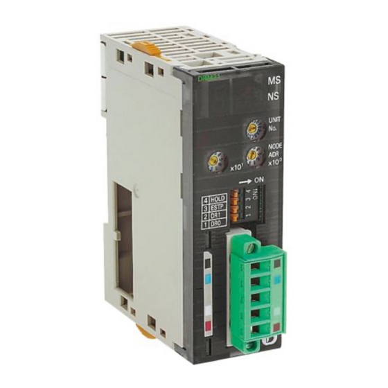
Nomenclature and Functions Section 2-1 Nomenclature and Functions 2-1-1 Nomenclature and Functions CS1W-DRM21(-V1) DRM21 Indicators Unit No. switch UNIT This switch sets the unit number of the DeviceNet Unit as a one-digit hexadecimal value. NODE Node address switches These switches set the node address as a two-digit 1 DR0 decimal value. -
Page 73: Status Indicators: Ms And Ns
Nomenclature and Functions Section 2-1 2. Two-digit, 7-segment display 1. Status indicators 3. Dot indicators 2-1-2 Status Indicators: MS and NS The MS (Module Status) indicator indicates the status of the node itself and the NS (Network Status) indicator indicates the status of the network. The MS and NS indicators can be green or red and they can be OFF, ON, or flashing (alternating 0.5-s ON and 0.5-s OFF.) The following table shows the meaning of these indicator conditions. -
Page 74: Seven-Segment Display
Nomenclature and Functions Section 2-1 2-1-3 Seven-Segment Display In addition to the MS and NS indicators, DeviceNet Units have a 2-digit, 7- segment display that normally indicates the master node address. When an error occurs, the display will alternate between the error code and the node address of the faulty slave. -
Page 75: Switch Settings
Use this switch to set the unit number of the DeviceNet Unit as a CPU Bus Unit. The unit number setting determines the CIO and DM area words allo- CS1W-DRM21(-V1) CJ1W-DRM21 cated to the Unit as software switches and the status area. - Page 76 CS1W-DRM21(-V1) Baud rate Continue/stop communications for communications error (when used as a master)
-
Page 77: Installing The Devicenet Unit
Installing the DeviceNet Unit Section 2-2 Continue/Stop Remote I/O Communications When the DeviceNet Unit is used as a master, pin 3 is used to set whether or not communications will stop after a communications error. Pin 3 Function Continue communications. Stop communications. -
Page 78: Mounting
Installing the DeviceNet Unit Section 2-2 • In the CS-series, up to 16 Units can be mounted to the CS1W-BC@@3 CPU Backplane or CS1W-BI@@3 Expansion CPU Backplane. • In the CJ-series, up to 16 Units can be mounted to the CPU Unit or Expansion Unit (but no more than 10 Units on either). -
Page 79: Handling Precautions
Installing the DeviceNet Unit Section 2-2 Note When mounting the Unit, provide the clearance shown below to facilitate easy mounting or dismounting. Duct 20 mm min. Backplane 20 mm min. Duct Phillips screwdriver CJ-series 1. Carefully align the connectors to mount the DeviceNet Unit. Connectors PA205 R POWER... - Page 80 Unit. • Remove the label after the completion of wiring to ensure proper heat dis- sipation. Leaving the label attached may result in malfunction. CS1W-DRM21(-V1) Remove the label after wiring. CJ1W-DRM21 Remove the label after wiring.
-
Page 81: External Dimensions
Installing the DeviceNet Unit Section 2-2 2-2-4 External Dimensions CS1W-DRM21(-V1) 13.7 DRM21 UNIT NODE 1 DR0 ESTP HOLD These diagrams show the dimensions of the DeviceNet Unit. Refer to the CS1 Series CPU Unit Operation Manual (W339) or the CJ Series CPU Unit Opera- tion Manual (W393) for the dimensions of the Unit when it is mounted to the Backplane. - Page 82 Installing the DeviceNet Unit Section 2-2...
-
Page 83: Allocated Cio And Dm Words
SECTION 3 Allocated CIO and DM Words This section describes the words allocated to the DeviceNet Unit in the CIO Area and DM Area. These words both enable controlling the DeviceNet Unit and accessing Unit and network status. Overview of Word Allocations ........3-1-1 Allocated CIO Area Words. -
Page 84: Overview Of Word Allocations
Overview of Word Allocations Section 3-1 Overview of Word Allocations The words shown in the following diagram are allocated according to the unit number setting. For each Unit, there are 25 words allocated in the CIO Area and 100 words allocated in the DM Area. First word allocated in the CIO Area: n = CIO 1,500 + (25 x unit number) First word allocated in the DM Area: m = D30,000 + (100 x unit number) DeviceNet Unit... -
Page 85: Allocated Cio Area Words
Overview of Word Allocations Section 3-1 3-1-1 Allocated CIO Area Words Software switches, DeviceNet Unit status, and error data are allocated in the CIO Area according to the unit number, as shown below. Software switches are bits used as commands from the CPU Unit to the DeviceNet Unit to enable executing Unit functions. -
Page 86: Allocated Cio Area Words
Allocated CIO Area Words Section 3-2 Allocated CIO Area Words Data is stored at the offset positions shown in the figure below starting from the first word allocated to the Unit in the CIO Area. The first word can be calculated as follows from the unit number setting: First word n = CIO 1,500 + (25 x unit number) Word Bit 15... - Page 87 Allocated CIO Area Words Section 3-2 • Unit status area 2 (word n+11) • Master Status 1 (word n+12) Word n [n = CIO 1,500 + (25 x unit number)] Name Status Con- Unit operation Operation condi- Default trolled tions setting Mas- Scan...
- Page 88 Allocated CIO Area Words Section 3-2 Name Status Con- Unit operation Operation condi- Default trolled tions setting Mas- Scan Unit list oper- func- sta- ating tion mode Remote OFF→ User Starts remote I/O communications. None I/O Com- abled Note 1. The switch is ignored if remote I/O commu- munica- nications are already running.
- Page 89 Allocated CIO Area Words Section 3-2 Name Status Con- Unit operation Operation condi- Default trolled tions setting Mas- Scan Unit list oper- func- sta- ating tion mode Master OFF→ User Enables master communications. (The Unit automati- Pro- Dis- Master Enable cally restarts.) gram abled...
- Page 90 Allocated CIO Area Words Section 3-2 Name Status Con- Unit operation Operation condi- Default trolled tions setting Mas- Scan Unit list oper- func- sta- ating tion mode Master OFF→ User Reads setup data from the Master User Allocations Pro- Master User-set Setup Table (words m+1 to m+7) in the DM Area and gram...
-
Page 91: Software Switches 2 (Word N+1)
Allocated CIO Area Words Section 3-2 Name Status Con- Unit operation Operation condi- Default trolled tions setting Mas- Scan Unit list oper- func- sta- ating tion mode Commu- OFF→ User Clears data in the Communications Cycle Time Refer- None nications ence Table (words m+15 to m+18). - Page 92 Allocated CIO Area Words Section 3-2 Name Status Con- Unit operation Operation Default trolled by conditions setting Slave Unit func- oper- tion ating mode Slave OFF→ User Enables slave communications. (The Unit automatically Pro- Dis- Slave Enable restarts.) gram abled disabled Switch mode...
- Page 93 Allocated CIO Area Words Section 3-2 Name Status Con- Unit operation Operation Default trolled by conditions setting Slave Unit func- oper- tion ating mode Slave OFF→ User Allocates the following words to the slave. Pro- Dis- Slave abled Fixed Allo- gram Fixed •...
-
Page 94: Master Cos Send Switches (Words N+2 To N+5)
Allocated CIO Area Words Section 3-2 Name Status Con- Unit operation Operation conditions Default trolled by setting Mas- Scan Slave Unit list func- oper- func- sta- tion ating tion mode Unit Setup OFF→ User Reads Unit settings (scan list, communica- Pro- None File... -
Page 95: Disconnect/Connect Switches (Words N+6 To N+9)
Allocated CIO Area Words Section 3-2 3-2-4 Disconnect/Connect Switches (Words n+6 to n+9) One Disconnect/Connect Switch is allocated to each slave node address. If the switch for a slave is turned ON, then remote I/O communications to that slave will be temporarily stopped (i.e., it is disconnected from the network). A communications error will occur at the end for any slave has been discon- nected if the corresponding switch is turned ON during communications. -
Page 96: Unit Status 1 (Word N+10)
Allocated CIO Area Words Section 3-2 3-2-5 Unit Status 1 (Word n+10) Word n+10 [n = CIO 1,500 + (25 x unit number)] Name Status Controlled Unit operation Unit Error Unit Displays DeviceNet Unit operating errors. Flag This bit turns ON if any bit from 01 to 15 in Unit Status 1 turns ON. (OR of bits 01 to 15) Usage example: When writing the ladder program for remote I/O commu- nications, set a NC input conditions for this bit to control Slave I/O pro-... -
Page 97: Unit Status 2 (Word N+11)
Allocated CIO Area Words Section 3-2 Name Status Controlled Unit operation Network Unit Indicates that there is no power from the network power supply. Power Error Note Remote I/O communications stop if DIP switch pin 3 (remote I/O Flag communications stop/continue setting for a communications error) on the front panel is ON (stop). - Page 98 Allocated CIO Area Words Section 3-2 Name Status Controlled Unit operation Remote I/O Unit Indicates that remote I/O communications are being performed for the Communica- master function. Normally, the Unit will perform remote I/O communica- tions Flag tions automatically. Note This bit only indicates the start of remote I/O communications, and does not indicate whether data has actually been exchanged with slaves.
-
Page 99: Master Status 1 (Word N+12)
Allocated CIO Area Words Section 3-2 3-2-7 Master Status 1 (Word n+12) Word n+12 [n = CIO 1,500 + (25 x unit number)] Name Status Controlled Unit operation Verification Unit Indicates that the data in the slave registered in the scan list is different Error Flag from the data from the actual slave. -
Page 100: Master Status 2 (Word N+13)
Allocated CIO Area Words Section 3-2 Name Status Controlled Unit operation Fixed Unit Indicates that an error has occurred in one of the following operations: Allocation • Fixed Allocation Setting 1 (word n, bit 08) Area Setting • Fixed Allocation Setting 2 (word n, bit 09) Failed Flag •... -
Page 101: Slave Status 1 (Word N+14)
Allocated CIO Area Words Section 3-2 3-2-9 Slave Status 1 (Word n+14) Word n+14 [n = CIO 1,500 + (25 x unit number)] Name Status Controlled Unit operation Reserved by system Remote I/O Unit Indicates that a communications error has occurred in the OUT 1/IN 1 Communica- slave I/O connection. - Page 102 Allocated CIO Area Words Section 3-2 Name Status Controlled Unit operation COS Send Unit Indicates that an attempt was made to send COS to a Master using the Failed Flag Slave COS send switch (Slave COS Send Switch in n+1) in Software Switches 2, but the transmission failed.
-
Page 103: Slave Status 2 (Word N+15)
Allocated CIO Area Words Section 3-2 3-2-10 Slave Status 2 (Word n+15) Word Bit 15 Bit 08 Bit 07 Bit 00 Slave I/O Allocation Status Master Node Address n+15 Master Node Addresses This indicates the node address of the remote master for slave communica- tions. -
Page 104: Normal Slave Table (Words N+20 To N+23)
Master Status Area 1, is provided for C200H DeviceNet Mas- ter Units. Word n+24 [n = CIO 1,500 + (25 x unit number)] Name Status Controlled C200HW- Details and CS1W-DRM21(-V1) status DRM21-V1 status Unit Memory ON/OFF Unit Switch Set-... - Page 105 Allocated CIO Area Words Section 3-2 Name Status Controlled C200HW- Details and CS1W-DRM21(-V1) status DRM21-V1 status Send Error ON/OFF Unit Send Error This bit turns ON if any one of the following bits turns ON: Flag Flag • Network Power Error Flag (word n+10, bit 07) •...
-
Page 106: Allocated Dm Area Words
Allocated DM Area Words Section 3-3 Allocated DM Area Words Data is stored at the offset positions shown in the figure below starting from the first word allocated to the Unit in the DM Area. The first word can be calculated as follows from the unit number setting: First word m = D30000 + (25 x unit number) Word Bit 15... -
Page 107: Master User Allocations Setup Table
Allocated DM Area Words Section 3-3 Word Bit 15 Bit 00 Communications cycle time setting (ms) Name Range Details Communications 0000 to 01F4 Hex Sets the communications cycle time in milli- Cycle Time Set- (0 to 500) seconds. Setting range: 0 to 500 ms ting If this bit is set to 0, the optimum time calcu- lated by the Unit will be used. - Page 108 Allocated DM Area Words Section 3-3 Note Make sure the CPU Unit is in PROGRAM mode and the master function is enabled before you set these values. Name Range Details OUT block 1 area See Areas and Specifies the OUT block area. The OUT Word Ranges.
-
Page 109: Allocation Size Setup Table
Allocated DM Area Words Section 3-3 Setting Results Code Description Details 0000 Completed normally 1101 No area • Incorrect area setting. • The allocated size in the allocation size setup table is 0. 1103 Address range specifi- The first word is outside the setting range. cation error 110C Parameter error... -
Page 110: Slave User Allocations Setup Table
Allocated DM Area Words Section 3-3 Setting Example The following example shows the allocation when the size (bytes) for OUT block 1 and IN block 1 is set in the allocation size setup table using the speci- fied values. Node address 0: OUT size: 1 byte, IN size: 5 bytes Node address 1: OUT size: 4 byte, IN size: 3 bytes Node address 2: OUT size: 1 byte, IN size: 2 bytes Allocation size setup table... - Page 111 Allocated DM Area Words Section 3-3 Name Range Details Slave OUT 1 area See Areas Specifies the OUT 1 area. The OUT 1 and Word area is not available if this is set at 0. Ranges. First word in the Slave OUT Specifies the first word in the OUT 1 area.
-
Page 112: Communications Cycle Time Reference Table
Allocated DM Area Words Section 3-3 3-3-5 Communications Cycle Time Reference Table This table can be used to access the present, maximum and minimum com- munications cycle times. All the values in this table are cleared from the Unit and the maximum and minimum values are updated with new values when the Communications Cycle Time Reference Table Clear Switch (word n, bit 13) is turned ON. -
Page 113: Slave User-Set Allocations Reference Table
Allocated DM Area Words Section 3-3 Ranges Name Range Details OUT block 1/2 area See Areas Shows the area. and Word First word in OUT Shows the first word for the block. Ranges. block 1/2 No. of bytes in OUT 0000 to Shows the block size in bytes. -
Page 114: Slave Detailed Status
Allocated DM Area Words Section 3-3 Note OUT2 is not used. Ranges Name Range Details OUT 1/2 area See Areas and Word Shows the area. Ranges. First word in the OUT block Shows the first word for the area. OUT 1/2 area size 00 to C8 Hex Shows the area by size in (0 to 200 bytes) - Page 115 Allocated DM Area Words Section 3-3 Name Status Controlled Unit operation 03, 11 Slave Unit Indicates that an error has occurred in remote I/O communications Remote I/O with the Slave. Communica- This bit turns ON if a timeout occurs in at least one connection with tions Error multiple connections set.
- Page 116 Allocated DM Area Words Section 3-3...
-
Page 117: Remote I/O Master Communications
SECTION 4 Remote I/O Master Communications This section describes the remote I/O communications performed as a DeviceNet master by the Devicenet Unit. Master Remote I/O Communications ....... 4-1-1 Allocations . -
Page 118: Master Remote I/O Communications
Master Remote I/O Communications Section 4-1 Master Remote I/O Communications Remote I/O communications are used to automatically transfer data between slaves and the CPU Unit without any special programming in the CPU Unit under which the Master Unit is mounted. Master Communications CS/CJ-series DeviceNet Unit (master) CS/CJ-series CPU Unit... - Page 119 Master Remote I/O Communications Section 4-1 Fixed Allocations Any one of the three areas below can be specified as the words allocated in the CIO Area for fixed allocations. The output (OUT) block and the input (IN) block are allocated strictly in order of node addresses in one of the areas shown below.
- Page 120 Master Remote I/O Communications Section 4-1 The OUT and IN blocks will be allocated in order of slave node addresses. Each block is a maximum of 500 words. CPU Unit Specified in allo- cated DM words Ascending order starting from address 0 Address To Slaves block 1...
-
Page 121: Remote I/O Master Specifications
Master Remote I/O Communications Section 4-1 4-1-2 Remote I/O Master Specifications Item Specifications Slave alloca- Fixed allo- Select one of the following fixed allocation areas using the Fixed Allocated Area Switches 1, tion methods cations 2, and 3 in the software switches in the allocated CIO Area words. Allocated Size Fixed Alloca-... -
Page 122: Precautions On The Number Of Master Units
Master Remote I/O Communications Section 4-1 Item Specifications Max. No. of I/O Fixed allocations 2,048 pts (64 input words, 64 output words) per Slave con- User-set By allocated 3,200 pts (100 input words, 100 output words) trollable by a allocations DM Area DeviceNet Unit words... -
Page 123: Procedure For Using Remote I/O Master
Master Remote I/O Communications Section 4-1 4-1-4 Procedure for Using Remote I/O Master Fixed Allocations for Remote I/O 1,2,3... 1. Turn ON the communications, slave, and PLC power supplies. Note Turn ON the communications power supply prior to turning ON the slave power supply or the slaves may not go online. - Page 124 4. Perform the following steps to allocate areas, create scan lists, and down- load the settings to the nodes. a) Create a network configuration offline on the Configurator. b) Enable master communications in the CS1W-DRM21(-V1) properties. c) Create master device parameters. d) Save the data as a network component file.
-
Page 125: Scan List
Scan List Section 4-2 nect/Connect Switch for that slave (words n+6 to n+9). This can be done when a slave is replaced or to register a slave in the scan list in prepara- tions to connect it to the network at a later time. The Disconnect/Connect Switches, however, are cleared when the power supply is turned OFF, so the bit must be turned back ON from the ladder program after the power turns ON in order for it to remain effective. - Page 126 Scan List Section 4-2 Creating the Scan List The way that a scan list is prepared varies with the allocation method as shown below. Fixed allocations User-set allocations User-set allocations through the allocated DM through the Configurator Area words area With the CPU Unit in PRO- With the CPU Unit in PRO- Create a list from the Con-...
-
Page 127: Fixed Allocations
Fixed Allocations Section 4-3 you disable the scan list with a Master Unit that is set for user-set allocations. Particularly when multiple Master Units are connected to a single network, communications will not be performed suc- cessfully if even one Master Unit on the network is operating with the scan list disabled. -
Page 128: Procedure
Fixed Allocations Section 4-3 Note More than one Master Unit can be included in a single PLC with fixed alloca- tions, as shown below (3 Units max.). Master Unit Master Unit Slave Slave 4-3-2 Procedure Step 1: Place the CPU Unit in PROGRAM mode. Step 2: Turn ON the If the master communications have been disabled (if Master Function Enable Master Enable Switch... - Page 129 Fixed Allocations Section 4-3 Fixed Allocations Area 1 OUT blocks are allocated to slaves from CIO 3200 to CIO 3263 and IN blocks are allocated to slaves from CIO 3300 to CIO 3363. OUT block CS/CJ-series DeviceNet CIO Area Address 0 CIO 3200 Address 1 CIO 3201...
- Page 130 16 I/O points. Note The table below shows how fixed allocations areas differ between the C200HW-DM21-V1 DeviceNet Master Unit of the C200H-series, and the CS1W-DRM21(-V1) DeviceNet Unit of the CS/CJ-series and CJ1W-DRM21 DeviceNet Unit of the CJ-series. Item C200HW-DRM21-V1...
-
Page 131: Changing System Components
Fixed Allocations Section 4-3 4-3-3 Changing System Components The scan list must be cleared in the following situations: • Adding a slave • Removing a slave • Changing a node address Turn OFF the Scan List Clear Switch (word n, bit 01) to clear the scan list. Remote I/O communications will be performed with the scan list disabled using fixed allocations in the fixed allocations area that was used the last time the list was disabled. - Page 132 Fixed Allocations Section 4-3 Note 1. The Master Unit does not require any word allocation and so it can use any available address. 2. Blocks for which allocation is enabled can be allocated to Slaves as long as the blocks do not overlap. Turn ON the Scan List Turn ON the Scan List Enable Switch (word n, bit 00, CIO 150000 in this Enable Switch...
-
Page 133: User-Set Allocations
User-set Allocations Section 4-4 User-set Allocations With a CS/CJ-series DeviceNet Unit, remote I/O communications slaves can be allocated in any area (CIO, WR, HR, DM, or EM) using one of the following methods. • Setting through the allocated DM Area words (Master User Allocations Table) •... - Page 134 User-set Allocations Section 4-4 • The first bit for node allocations is always bit 00 when setting alloca- tions with the allocated DM Area words, but can be either bit 00 or bit 08 with the Configurator. (Allocations for slaves with two bytes or more cannot start at bit 08.
- Page 135 User-set Allocations Section 4-4 Procedure Step 1: Turn ON the Master Enable Switch Make sure that master communications have disabled by checking to see if Master Enable Function Flag (word n+11, bit 03) is OFF and then turn ON the Master Enable Switch (word n, bit 06) to enable master communications.
- Page 136 User-set Allocations Section 4-4 l is the first word in the Allocation Size Setup Table and is specified at words m+5 and m+6 08 07 Node address 0 OUT size (bytes) Node address 0 IN size (bytes) Node address 1 IN size (bytes) Node address 1 OUT size (bytes) I+62 Node address 62 OUT size (bytes)
- Page 137 User-set Allocations Section 4-4 4. Multiple masters cannot share the same slave. Master Master Slave 5. Be sure to use user-set allocations and operate the Master Unit with the scan list enabled if multiple masters are connected to a single network. Communications will not be possible if there is more than one master with the scan list disabled connected to a network.
- Page 138 User-set Allocations Section 4-4 Allocation Size Setup Table OUT sizes specified IN sizes specified in in the leftmost byte the rightmost byte Address 0 OUT: 2 (bytes) Address 0 IN: 0 (bytes) Address 1 OUT: 1 (bytes) Address 1 IN: 1 (bytes) Address 2 OUT: 2 (bytes) Address 2 IN: 2 (bytes) Address 3 OUT: 0 (bytes)
- Page 139 User-set Allocations Section 4-4 Setting through the Slaves can be allocated words in any order for the following blocks: OUT block Configurator 1, OUT block 2, IN block 1, and IN block 2. OUT block 1 User-set block order Specified area in I/O memory Address User-set block order First word...
- Page 140 User-set Allocations Section 4-4 Procedure Step 1 Set the area, start word, and words allocated for each block using the Config- urator. Step 2 Allocate words to all node addresses in each block as shown below using the Configurator. OUT block 1 Node address 00 Node address 00: DRT1-OD16 (16 output pts) Node address 03...
- Page 141 User-set Allocations Section 4-4 d) The start bit for node addresses can be bit 00 or bit 08. If it is bit 08 however, 2 or more bytes cannot be allocated as shown below. Start byte e) Multiple masters cannot share the same slave. Master Master Slave...
-
Page 142: Starting And Stopping Remote I/O Communications
Starting and Stopping Remote I/O Communications Section 4-5 Configurator Setting Methods Refer to the DeviceNet Configurator Operation Manual (W382) for setting methods. Starting and Stopping Remote I/O Communications 4-5-1 Starting Remote I/O Communications Remote I/O communications start automatically after the power is turned ON or the Unit is restarted. - Page 143 Example of Ladder Programming for Remote I/O Communications Section 4-6 I/O Data Communications Unit Error Flag Flag (word n+12, bit 15) (word n+10, bit 00) Slave I/O processing Note Even if there is a communications error with the slave, the slave input data is saved in the allocated area.
-
Page 144: Errors That May Occur In Remote I/O Communications
Errors that May Occur in Remote I/O Communications Section 4-7 Errors that May Occur in Remote I/O Communications The following errors may occur during remote I/O communications. Condition Error Details Results Indicators segment display Error Structure Duplicate I/ The same I/O word is allocated to Reconnect with MS: Not occurs in... - Page 145 Errors that May Occur in Remote I/O Communications Section 4-7 Condition Error Details Results Indicators segment display Fixed or I/O communications error A timeout occurred during remote Reconnect with MS: Not user-set I/O communications. (The Slave the error Slave related allocations response timed out 6 times in a and continue...
- Page 146 Errors that May Occur in Remote I/O Communications Section 4-7...
-
Page 147: Remote I/O Slave Communications
SECTION 5 Remote I/O Slave Communications This section describes the remote I/O communications performed as a DeviceNet slave by the DeviceNet Unit. Slave Remote I/O Communications ....... . 5-1-1 Allocation Methods . -
Page 148: Slave Remote I/O Communications
Slave Remote I/O Communications Section 5-1 Slave Remote I/O Communications A CS/CJ-series DeviceNet Unit can function as a Slave Unit in remote I/O communications and a single CS/CJ-series DeviceNet Unit can function as both a Master Unit and a Slave Unit. This section describes Slave communi- cations. -
Page 149: Remote I/O And Slave Communications Specifications
Slave Remote I/O Communications Section 5-1 5-1-2 Remote I/O and Slave Communications Specifications Item Specifications Allocation Fixed allo- Select one of the following fixed allocation areas using the Slave Fixed Allocated Area method cations Switches 1, 2, and 3 in the software switches in the allocated CIO Area words. Allocated words Size Fixed Allo-... - Page 150 4. Perform the following steps to allocate areas, create scan lists, and down- load the settings to the nodes. a) Enable slave communications in CS1W-DRM21(-V1) or CJ1W- DRM21 properties using the Configurator. b) Create the device parameters to set slave communications.
-
Page 151: Fixed Allocations
Fixed Allocations Section 5-2 Note 1. Enable slave communications in CS1W-DRM21(-V1) or CJ1W-DRM21 properties if the Configurator is used. 2. Use Configurator Ver. 2.10 or higher for the CJ1W-DRM21. Fixed Allocations 5-2-1 Allocated Words Words in the CS/CJ-series DeviceNet CIO Area in the CPU Unit are allocated. -
Page 152: User-Set Allocations
User-set Allocations Section 5-3 Fixed Allocation Area 1 CS/CJ-series DeviceNet CIO Area Master Slave OUT area Output (OUT) area CIO 3370 Input (IN) area IN area CIO 3270 Fixed Allocation Area 2 CS/CJ-series DeviceNet CIO Area Master Slave OUT area Output (OUT) area CIO 3570 Input (IN) area... -
Page 153: Connection Types
User-set Allocations Section 5-3 2. Only two blocks (OUT 1 and IN 1) can be allocated when setting are made with the allocated DM Area words area, but there are three blocks (OUT 1 and IN 1/2) available with the Configurator. Setting through the Allocated DM Area Words (Slave User Allocations Table) Words can be allocated for the OUT 1 area (master to Slave Unit) and IN 1 area (Slave Unit to master) from any specified I/O memory location specified... - Page 154 User-set Allocations Section 5-3 • Areas and Word Ranges for the OUT 1/IN 1 Areas Code Name Word range 00 Hex The block is not used. 01 Hex CIO Area (CIO) 0000 to 17FF Hex (0 to 6143) 03 Hex DM Area (DM) 0000 to 7FFF Hex (0 to 32767) 04 Hex...
- Page 155 User-set Allocations Section 5-3 • Slave User Allocations Table OUT block 1 area: WR (04 Hex) First word of OUT block 1: 50 (0032 Hex) OUT block 1 size: 20 bytes (14 Hex, 10 words) IN block 1 area: WR (04 Hex) First word of IN block 1: 100 (0064 Hex) IN block 1 size: 10 bytes (0A Hex, 5 words) •...
-
Page 156: Connection Types
User-set Allocations Section 5-3 Setting through the A maximum of three blocks can be allocated at any locations in I/O memory Configuration for the output (OUT) area block 1, input (IN) area block 1, and input (IN) area block 2. Specified area in I/O memory Master User-set block order... - Page 157 User-set Allocations Section 5-3 Connection Types and Allocated I/O Areas The following table shows the relationship between various connection combi- nations and the allocated areas that are applicable with those connections. Specified connection OUT 1 area IN 1 area IN 2 area type Poll Poll OUT data...
- Page 158 User-set Allocations Section 5-3...
-
Page 159: Message Communications
SECTION 6 Message Communications This section describes message communications using FINS commands sent from the ladder program in the CPU Unit of the PLC. Overview ........... . . 6-1-1 Outline of Message Communications. -
Page 160: Overview
Message communications enable messages to be set between nodes on a DeviceNet network when required by system conditions. The messages can be sent between PLCs, between an OMRON PLC and a master made by another company, or between slaves. They can be used to send/receive data;... -
Page 161: Fins Message Communications
Explicit (2801 Hex) FINS message Explicit message function OMRON special message communications FINS message DeviceNet network DeviceNet message communications Explicit message Note If only the message communications function is being used and the remote I/O communications function is not being used, message communications are possible even if the master function is disabled. - Page 162 Overview Section 6-1 Note 1. The DeviceNet Unit must be registered in the local network routing table of the CS/CJ-series PLC when two or more Communications Units (including the DeviceNet Unit) are mounted to a CS/CJ-series PLC. The commands will not be sent if the Unit is not registered in the routing tables. 2.
-
Page 163: Explicit Message Communications
V1) or CVM1/CV-series DeviceNet Master Units (CVM1-DRM21-V1). 6-1-3 Explicit Message Communications Service requests can be sent to C200H I/O Link Units and other OMRON slaves, PLCs with CS/CJ-series DeviceNet Units, and DeviceNet masters and slaves made by other manufacturers using explicit messages defined for DeviceNet. -
Page 164: Message Communications Specifications
Note A specific FINS command (command 2801) is used to send explicit messages. Note This CS/CJ-series DeviceNet Unit (CS1W-DRM21(-V1) or CJ1W-DRM21) contains a PLC Object so that the I/O memory of the CPU Unit of the DeviceNet Unit can be read/written from other devices. The C200HW-DRT21 I/O Link Unit also contains a PLC Object so that the I/O memory of the CPU Unit of the I/O Link Unit can be read/written from other devices. -
Page 165: Message Communications Error Indications
Overview Section 6-1 Item Specification No. of simultaneous instructions One each for 8 ports (ports 0 to 7) Refer to 3-25 Network Instructions in the CS/CJ Series Programmable Controllers Instructions Reference Manual (W340) for information on ports (logical ports). Response monitoring time Default setting: User setting: 0.1 to 6553.5 s... -
Page 166: Message Monitoring Timer
Overview Section 6-1 Example: Routing table error Flashing red Not relevant Master Status Area 1 Device- Net Unit Unit 6-1-6 Message Monitoring Timer A message monitoring timer monitors responses for the DeviceNet Unit. A timer can be set for each device that will be communicated with (each mes- sage destination). -
Page 167: Fins Commands And Responses
FINS Commands and Responses 6-2-1 FINS Communications The FINS communication protocol was developed by OMRON for use with factory automation control devices. FINS communications enable PLC mem- ory read/write and operation control without extensive programming in the user program in the PLC. FINS communications use an independent system of addresses that does not rely on the addresses used in the DeviceNet net- work. -
Page 168: Sending/Receiving Fins Command/Responses
FINS Commands and Responses Section 6-2 Refer to SYSMAC CS/CJ Series Communication Commands Reference Man- ual (W342) for details on FINS commands. 6-2-2 Sending/Receiving FINS Command/Responses FINS commands are sent using the CMND(490) instruction for CS/CJ-series PLCs. Send/receive FINS commands and responses and the data formats used are illustrated in the following diagram. -
Page 169: Units Supporting Fins Communications
FINS Commands and Responses Section 6-2 The main response codes are listed below. Refer to SYSMAC CS/CJ Series Communication Commands Reference Manual (W342) for further details on response codes, including sub-response codes (SRES). Main code Main code 00: Normal completion 20: Read not possible 01: Local node error 21: Write not possible... - Page 170 FINS Commands and Responses Section 6-2 Function Name Command code Controlling access rights ACCESS RIGHT ACQUIRE ACCESS RIGHT FORCED ACQUIRE ACCESS RIGHT RELEASE Manipulating error data ERROR CLEAR ERROR LOG READ ERROR LOG CLEAR Manipulating File Memory FILE NAME READ SINGLE FILE READ SINGLE FILE WRITE MEMORY CARD FORMAT...
-
Page 171: Using Fins Message Communications
Using FINS Message Communications Section 6-3 Using FINS Message Communications There are two instructions that can be executed to send and receive data from CS/CJ-series CPU Units: SEND(090) and RECV(098). There is another instruction that can be executed to send any FINS command: CMND(490). 6-3-1 Setting Node Addresses Set the nodes for FINS message communications to node addresses other... - Page 172 Using FINS Message Communications Section 6-3 Routing Tables The routing tables register the communications path from a Communications Unit on the local PLC, such as a DeviceNet Unit, Controller Link Unit, SYS- MAC LINK Unit, or Ethernet Unit, to the network to which the remote PLC is connected.
- Page 173 Procedure for Creating the Routing Table Use the CX-Net function for creating/sending routing tables in the CX-Pro- grammer, with the following procedure. 1. Select Start/Program/Omron/CX-Server/CX-Net Network Configura- tion Tool to start the CX-Net. 2. Select Edit/FINS Local from the Routing Table Menu. The following PLC Routing Table Window will appear.
-
Page 174: Data Send/Receive Instructions
Using FINS Message Communications Section 6-3 4. Use the left-side table to create the local network table. Input the unit num- bers and corresponding local network addresses. 5. Use the right-side table to create the relay network table. Input the final net- work addresses and corresponding relay network addresses and relay node addresses. - Page 175 Using FINS Message Communications Section 6-3 2. Values of $00 to $3F indicate nodes 0 to 63. 3. Designates the length of time that the PLC retries transmission when bit 15 of C+3 is OFF and no response is received. The default value is $0000, which indicates 2 seconds.
-
Page 176: Sending Fins Commands
Using FINS Message Communications Section 6-3 6-3-4 Sending FINS Commands DELIVER COMMAND: CMND(490) Description CMND(490) can be used in the user program of the CS/CJ-series CPU Unit to send FINS commands to read/write I/O memory, read status data, change the operating mode, and perform other functions at other nodes. -
Page 177: Using Send(090), Recv(098), And Cmnd(490)
Using FINS Message Communications Section 6-3 Note Explicit messages can be sent to OMRON slaves and DeviceNet devices made by other manufacturers by setting the FINS command code to 28 01. When this is done, set the response monitoring time in C+5 to at least the value set for the message monitoring timer (default: 2 s). - Page 178 Using FINS Message Communications Section 6-3 ted Flag and the NS indicators on the front of the DeviceNet Unit is shown in the following table. Message Network status Communications indicator Permitted Flag Communications connection made (network nor- Lit green mal) Communications connection not made (network Flashing normal, but communications not established)
- Page 179 Using FINS Message Communications Section 6-3 Send/Receive Data Areas The size of the data areas that can be used with SEND and RECV depends on the PLC that is being used. The following table shows the areas that can be used for CS/CJ-series PLCs. Data Area Range CIO Area...
- Page 180 Using FINS Message Communications Section 6-3 Program Example A202 (071) BSET #1234 D01000 D01004 Sets 1234 in D01000 to D01004. First Scan Flag (021) #0005 D00000 Places data into control data words to specify the 5 words to be transmitted to the CPU Unit of node 06 of network 01, through port 0, with response, 0 retries, (021) and a response monitoring time of 10.0 seconds.
- Page 181 Using FINS Message Communications Section 6-3 Example 2: Sending a FINS Command Using CMND CS/CJ-series CMND CS/CJ-series DeviceNet Unit No. 0 DeviceNet Unit Unit Unit Unit ad- dress: 00 Node 05 Node 06 Network 01 MEMORY AREA READ command Operation •...
-
Page 182: Connecting Networks For Fins Communications
Using FINS Message Communications Section 6-3 Example Program A500 (071) BSET #0000 D00000 D02999 Sets 0000 in D00000 to D02999. First Scan Flag (021) #0008 D00000 Place data into control data words to specify to read 5 words D01000 to D01004 from the PLC of node 06 and network 01 to the PLC of node 05. -
Page 183: Sending Explicit Messages
Sending Explicit Messages Section 6-4 Up to 3 levels of networks, including DeviceNet, are possible. Controller Link Unit Controller Link Unit CS/CJ-series DeviceNet Unit CS/CJ-series CPU Unit Remote I/O communications DeviceNet CS/CJ-series DeviceNet Unit Controller Link CS/CJ-series DeviceNet DeviceNet Unit When connecting networks, routing tables must be registered for the PLC CPU Units on all networks. -
Page 184: Sending Explicit Messages
The local DeviceNet Unit is specified as the destination in the communica- tions instruction in the PLC’s user program (not the OMRON Special Slave or DeviceNet device made by another manufacturer), and the node address of the actual destination (i.e., the Slave or Master made by another manufac- turer) is specified in the command data for the explicit message send com- mand. - Page 185 The following diagram shows an example of actual node address specifica- tions. Machine No. of DeviceNet Unit: 2 The node address of the non-OMRON node is set as the CMND destination node address in the FINS command data. Command code...
-
Page 186: Sending Explicit Messages Using Cmnd(490)
5. Contact the ODVA to obtain copies of the DeviceNet specification. ODVA's URL: http://www.odva.org/ 6. For details on explicit messages to OMRON Special I/O Slaves, refer to the DeviceNet Slaves Operation Manual (W347). 6-4-2 Sending Explicit Messages Using CMND(490) CMND(490) can be used in the CPU Unit ladder program of the CS/CJ-series DeviceNet Unit to send explicit messages. - Page 187 Sending Explicit Messages Section 6-4 Command data is set in order starting with the word specified for the CMND(490) operand S (first command word) and continuing with words with higher addresses in I/O memory in the command block format. Command Format Example: Writing Error Clear Codes to the CPU Unit Set in this order starting from the word specified for the CMND(490) operand S (first command word) and continuing with words with higher addresses.
- Page 188 Slave node 11 Operation The vendor code is read from a Slave (OMRON vendor code: 002F Hex) using the EXPLICIT MESSAGE SEND command, 28 01. The command data is written starting at DM01000, and the response data is stored starting at D02000.
- Page 189 Sending Explicit Messages Section 6-4 Settings (Hex). D00000 = 0009: Number of command bytes D00001 = 000A: Number of response bytes D00002 = 0001: Destination network address: 1 D00003 = 05FE: Destination node address: 05 Destination unit address: FE (or 10) D00004 = 0000: Response, communications port 0, no retries D00005 = 0064:...
-
Page 190: Receiving Explicit Messages
Receiving Explicit Messages Section 6-5 Program Example A200 (071) BSET #0000 D00000 D02999 Sets 0000 in D00000 to D02999. First Scan Flag (021) #0009 D00000 Place data into control data words to specify sending 9 bytes to node 05 (unit FE) on network 01 and to receive 10 bytes in return. -
Page 191: List Of Plc Object Services
Receiving Explicit Messages Section 6-5 • PLCs with CVM1/CV-series DeviceNet Master Units (CVM1-DRM21-V1) • PLCs with CS/CJ-series DeviceNet Units Example CS/CJ-series C200H-series DeviceNet Unit DeviceNet Master Unit C200HX/HG/HE CPU Unit CS/CJ-series CPU Unit Other manufacturer master Explicit messages can be received Explicit message DeviceNet Note Status and the I/O memory read/write operations cannot be performed for... - Page 192 Receiving Explicit Messages Section 6-5 I/O Memory Read/Write for CPU Units Service Service Class ID Instance ID Request Contents code service data Byte Data Read 1C Hex 2F Hex Specifies Address, No. Reads the specified node data in byte units. area (01 Hex of read bytes The word data is read in order, from high to...
- Page 193 Receiving Explicit Messages Section 6-5 CPU Information Read (Service Code: 0E Hex) Reads CPU Unit information, including operating mode, fatal/non-fatal errors, and the CPU Unit model. Command Block Class ID Attribute ID Service Code Instance ID Note A body format of either 8 bits or 16 bits is possible. Response Block Service Code Attribute Value...
- Page 194 Receiving Explicit Messages Section 6-5 Note The codes for the above modes are 1-word (2-byte) data and are returned in low byte first. For example, for PROGRAM mode, the code is returned as 01 Hex followed by 00 Hex. • CPU Unit Errors (when Attribute ID = 65 Hex) The CPU Unit fatal/non-fatal error data is returned in 1-word (2-byte) hexa- decimal format, as follows: 01 Hex: Error;...
- Page 195 Receiving Explicit Messages Section 6-5 The Attribute Values are as follows: 0001 Hex: PROGRAM mode; 0002 Hex: MONITOR mode; 0004 Hex: RUN mode Note The specified code for the above operating modes are 1-word (2-byte data, and are specified with the low byte first. For example, for PRO- GRAM mode, the code is specified as 01 Hex followed by 00 Hex.
- Page 196 Receiving Explicit Messages Section 6-5 CPU Unit Status Read (Service Code: 40 Hex) This PLC Object service reads status details (operation status, operating mode, fatal and non-fatal errors, etc.) from the CPU Unit. Command Block Service Code Instance ID Class ID Note A body format of either 8 bits or 16 bits is possible.
- Page 197 Receiving Explicit Messages Section 6-5 1: System error (FALS) 1: Cycle time over 1: Program error 1: I/O setting error 1: No. of I/O points exceeded 1: Inner Board fatal error 1: Number duplicate use error 1: I/O Bus error 1: Memory error •...
- Page 198 Receiving Explicit Messages Section 6-5 Note For information on the severity of error codes, refer to the CS1 Series CPU Unit Operation Manual (W339) or the CJ Series CPU Unit Op- eration Manual (W393). • Error Messages: If the above error codes have occurred when FAL/FALS instructions are executed with registered messages, those messages are returned in 16-byte ASCII.
- Page 199 Receiving Explicit Messages Section 6-5 No. of bytes received (response): The number of bytes received from the destination node address (remote node) is returned in hexadecimal. Destination node address (response): The node address of the CS/CJ- series DeviceNet Unit that returned the response is returned in hexadecimal. Read data (response): The specified area, word, and byte data is returned in order from word H (high byte: bits 8 to 15) to word L (low byte: bits 0 to 7).
- Page 200 Receiving Explicit Messages Section 6-5 Address H: The higher 2 digits when the first word address is given in 4-digit hexadecimal. No of Read Words (command): The number of words of read data is speci- fied in 1-byte (2-digit) hexadecimal. The range is 01 to 64 Hex (1 to 100 deci- mal).
- Page 201 Receiving Explicit Messages Section 6-5 Address H: The higher 2 digits when the first word address is displayed in 4- digit hexadecimal. Write data (response): The specified area and write data is returned in order from word H (higher byte: bits 8 to 15) to word L (lower byte: bits 0 to 7). If an odd number is specified, the last 1 byte of data will be written to word H.
- Page 202 Receiving Explicit Messages Section 6-5 Write data (response): The specified area and write data is returned in order from word L (lower byte: bits 0 to 7) to word H (higher byte: bits 8 to 15). Important Points The actual address L, address H, and number of read words that can be spec- ified depends on the mode of CPU Unit for the CS/CJ-series DeviceNet Unit and the type of memory areas.
-
Page 203: Other Functions
SECTION 7 Other Functions This section describes connecting to CX-Programmer via the DeviceNet and the Memory Card backup function. Connecting to the CX-Programmer via the DeviceNet....7-1-1 Setting Node Addresses . -
Page 204: Connecting To The Cx-Programmer Via The Devicenet
Connecting to the CX-Programmer via the DeviceNet Section 7-1 Connecting to the CX-Programmer via the DeviceNet With CX-Programmer Ver. 2.1 or higher, a serial connection can be made to a PLC containing a CS/CJ-series DeviceNet Unit to form an online connection, via the DeviceNet, to other PLC CPU Units on the network. -
Page 205: Setting Node Addresses
Connecting to the CX-Programmer via the DeviceNet Section 7-1 7-1-1 Setting Node Addresses When the CX-Programmer is connected online, it uses FINS message com- munications. It is thus necessary to set the node address to a number other than 0 for DeviceNet Units mounted to the target PLC, DeviceNet Units mounted to a PLC which is connected by a serial connection to the CX-Pro- grammer, or DeviceNet Units mounted to a PLC relaying between networks. - Page 206 Connecting to the CX-Programmer via the DeviceNet Section 7-1 2. Double-click on the node address (#) that you want to change, or select the node address and click on the Edit Button. A dialogue box like the one be- low will appear. 3.
-
Page 207: The Devicenet
Connecting to the CX-Programmer via the DeviceNet Section 7-1 response monitor time in the CMND/SEND/RECV instruction to be the same as or slightly longer than the time for the message monitoring timer (Response monitor time in the CMND/SEND/RECV instruction ≥ message monitoring timer.) If time-outs occur frequently, increase both of the set- tings equally, while maintaining the relationship between them. -
Page 208: Memory Card Backup Functions
Memory Card Backup Functions Section 7-2 a maximum of four-fold (for a communications speed of 500 Kbps) in com- parison with connection by a peripheral bus. 2. Temporarily extend the communications cycle time. Operate the CX-Programmer after extending the cycle time in the Commu- nications Cycle Time Setup Table (word m) in the DM Area, and turning ON the Temporary Setting Switch for Communications Cycle Time (word n, bit 12). -
Page 209: Outline Of Functions
Memory Card Backup Functions Section 7-2 Unit Setup File Backup Switch DeviceNet Unit CPU Unit Unit Setup File Restore Switch Configurator (computer) All setup Memory Card data Backup Save file Restore Load file 7-2-1 Outline of Functions 1. Backing Up Unit Setup Files Saves all internal Unit setup data to the Memory Card mounted to the CPU Unit. -
Page 210: File Names
Memory Card Backup Functions Section 7-2 DeviceNet Unit CPU Unit Unit Setup File Restore Switch All setup Memory Card data Restore Note If there is an error in the setup data or if the file could not be read, the File Read/Write Error bit in Unit Status 2 (word n + 11, bit 08) will turn ON. -
Page 211: Simple Backup Function
• Comparing data Note The following table shows the Units that support the simple backup function. Make sure that the Units being used support the function. CPU Unit DeviceNet Unit CS1W-DRM21-V1 CS1W-DRM21 CJ1W-DRM21 CS1-H CPU Unit CS1 CPU Unit CJ1-H CPU Unit CJ1 CPU Unit Note The DeviceNet Unit’s setup data that is created as a Unit/Board backup file is... -
Page 212: Operating Methods
Simple Backup Function Section 7-3 7-3-3 Operating Methods Backing Up DeviceNet Unit Setup Files to Memory Card Set the DIP switch on the front panel of the CPU Unit, as shown in the follow- ing table, and press down the Memory Card Power Supply Switch for 3 sec- onds. - Page 213 Simple Backup Function Section 7-3 When the power supply is ON, the MCPWR indicator on the front of the CPU Unit will turn ON, flash once, and then will remain lit while data is being read. After the data is read correctly, the indicator will turn OFF. Note The 7-segment display on the front panel will display “H8”...
- Page 214 CS1-H CPU Units CJ Series CJ1-H CPU Units CJ1 CPU Units CJ1M CPU Units CJ1-H CPU Units Applicable CS Series CS1W-DRM21-V1 only CS1W-DRM21-V1 DeviceNet Units CS1W-DRM21 CJ Series CJ1W-DRM21 CJ1W-DRM21 Back up, restore, and compare data The following setup data in the DeviceNet Unit’s internal non-volatile memory (EEPROM): •...
-
Page 215: Communications Timing
SECTION 8 Communications Timing This section describes the time required for remote I/O communications and message communications. Remote I/O Communications Characteristics......8-1-1 Communications Cycle Time and Refresh Time . -
Page 216: Remote I/O Communications Characteristics
Remote I/O Communications Characteristics This section describes the characteristics of remote I/O communications when the DeviceNet Unit is used as a master in combination with OMRON’s slaves. Use this section for reference when planning operations that require precise I/O timing. - Page 217 Remote I/O Communications Characteristics Section 8-1 Communications Cycle Use the equations shown below to calculate the communications cycle time ) for a network with one Master. Note that if the result of this calculation is Time Calculation less than 2 ms, the actual communications cycle time will be 2 ms. = Σ...
- Page 218 Remote I/O Communications Characteristics Section 8-1 = 0.016 × T × (S ) + 0.11 × T Mixed I/O Slaves with Less + 0.07 [ms] OUT2 Than 8 Bytes of Input or : The number of Mixed I/O Slave output words OUT2 Output The number of Mixed I/O Slave input words...
-
Page 219: I/O Response Time
Remote I/O Communications Characteristics Section 8-1 8-1-2 I/O Response Time Maximum I/O Response Time Communications Cycle The maximum I/O response time will be as shown below if the DeviceNet Unit Time ≥ PLC Cycle Time takes in data immediately after I/O refreshing and if the communications cycle time is longer than the PLC cycle time. - Page 220 Remote I/O Communications Characteristics Section 8-1 Network’s communications cycle time (See page 195.) The PLC’s cycle time (See note below.) Note The PLC’s cycle time will be delayed as shown below for one De- viceNet Unit. For details, refer to Refresh Time on page 196. 0.7 ms + (number of occupied words ×...
-
Page 221: More Than One Master In Network
Remote I/O Communications Characteristics Section 8-1 8-1-3 More than One Master in Network The following equation shows the remote I/O communications cycle time ) when there is more than one master in the network. An example for two masters is used. First, the network is divided into two groups: Master A and the slaves in remote I/O communications with it and master B and the slaves in remote I/O communications with it. -
Page 222: Message Communications
Message Communications Section 8-2 Case Slave’s indicator status System startup time The Master is The NS indicator is OFF or flashing green. 5 seconds started just after Slave startup. Just the Master is The NS indicator is flashes red while the Mas- 7 seconds restarted. -
Page 223: Calculating The Maximum Message Response Time
Message Communications Section 8-2 The baud rate factor (500 kbps: T = 2; 250 kbps: T = 4; 125 kbps: T = 8) Note The communications cycle time will be 2 ms even if remote I/O communica- tions are not being used. Remote I/O and Message Communications Performing message communications in addition to remote I/O communica- tions will increase the message communications time. - Page 224 Message Communications Section 8-2 Request from One Client (BYTE DATA READ) Instruction Instruction execution execution BYTE DATA READ processing time: PLC's cycle time x 2 Shared memory DeviceNet internal buffer Communications cycle Read request Client Read result Shown below is the response time required to return data for 100 words. •...
- Page 225 Message Communications Section 8-2 • BYTE DATA READ response receiving time: T DeviceNet header (3 bytes) + Number of words to be read x 2 = 203 bytes Therefore, T = 1 + 203 bytes/6 communications cycle time = 35 com- munications cycle time •...
- Page 226 Message Communications Section 8-2...
-
Page 227: Troubleshooting And Maintenance
SECTION 9 Troubleshooting and Maintenance This section describes error processing, periodic maintenance operations, and troubleshooting procedures needed to keep the DeviceNet network operating properly. We recommend reading through the error processing procedures before operation so that operating errors can be identified and corrected more quickly. Troubleshooting with the DeviceNet Unit Indicators . -
Page 228: Troubleshooting With The Devicenet Unit Indicators
Troubleshooting with the DeviceNet Unit Indicators Section 9-1 Troubleshooting with the DeviceNet Unit Indicators 9-1-1 Determining Operating Status from the Indicators The following table shows the status of the MS and NS indicators and the 7- segment display during normal operation. Indicator status Network/Unit status Comments... -
Page 229: Troubleshooting Errors Occurring In The Devicenet Unit
Troubleshooting with the DeviceNet Unit Indicators Section 9-1 9-1-2 Troubleshooting Errors Occurring in the DeviceNet Unit Error cate- Error Indicators Error Page gory 7-segment (Hex) Master func- Remote I/O communications stopped by 0346 tion a communications error Software set- CPU Unit status error tings errors Unit status error Structure error... - Page 230 Troubleshooting with the DeviceNet Unit Indicators Section 9-1 remote I/O communications for a communications error, two errors can be displayed: The slave’s communications error and its most recent error. Master Errors Remote I/O Communications Stopped 7-segment MS indicator NS indicator Error log (Hex) by a Communications 0346...
- Page 231 Troubleshooting with the DeviceNet Unit Indicators Section 9-1 Correction Set the slaves’ node addresses again. Structure Error: I/O Area Range Exceeded 7-segment MS indicator NS indicator Error log (Hex) Red (flashing) 0343 Likely Cause The slave’s I/O area isn’t within the allowed range. (Occurs with the scan list disabled.) DeviceNet Unit Response Records the error in the error log.
- Page 232 Troubleshooting with the DeviceNet Unit Indicators Section 9-1 Flags Allocated for C200H DeviceNet Master Unit (CIO n+24) Bit 14 (Error Flag) and bit 07 (Comparison Error Flag) will be ON. CIO Area Flags Allocated to DeviceNet Unit Bit 00 of n+12 (Comparison Error Flag) and bits 00 and 01 of n+10 (Unit Error Flag and Master Function Error Flag) will be ON.
- Page 233 Troubleshooting with the DeviceNet Unit Indicators Section 9-1 Correction Inspect the slave and then create the scan list again. Verification Error: I/O Size Mismatch 7-segment MS indicator NS indicator Error log (Hex) Red (flashing) 0344 Likely Cause The slave’s I/O data size does not match the registered scan list. (Occurs with the scan list enabled.) DeviceNet Unit Response Records the error in the error log.
- Page 234 Troubleshooting with the DeviceNet Unit Indicators Section 9-1 DeviceNet Unit Response Records the error in the error log. The master will periodically attempt to reconnect with the slave with the verifi- cation error. Flags Allocated for C200H DeviceNet Master Unit (CIO n+24) Bit 14 (Error Flag) and bit 07 (Comparison Error Flag) will be ON.
- Page 235 Troubleshooting with the DeviceNet Unit Indicators Section 9-1 • Matching master and slave baud rates • Proper cable lengths (trunk and branch lines) • Broken or loose cables • Installation of terminators at both ends of the trunk line • Excessive noise Software Switch Setting Errors CPU Unit Status Error 7-segment...
- Page 236 Troubleshooting with the DeviceNet Unit Indicators Section 9-1 Likely Cause The setting operation failed because a structure error occurred. DeviceNet Unit Response The only response is the error code displayed on the 7-segment display. The error display will be cleared the next time that a settings operation is com- pleted normally.
- Page 237 Troubleshooting with the DeviceNet Unit Indicators Section 9-1 return to normal when the network power supply is restored, although scan- ning will not resume if the DeviceNet Unit is set to stop remote I/O communi- cations when a communications error occurs. Flags Allocated for C200H DeviceNet Master Unit (CIO n+24) Bit 14 (Error Flag) and bit 05 (the Sending Error Flag) will be ON.
- Page 238 Troubleshooting with the DeviceNet Unit Indicators Section 9-1 DeviceNet Unit Response Records the error in the error log. • The Unit will go off–line and communications will be disabled. Error responses will be returned to all communications requests. • The exchange of data with the CPU Unit will continue. Flags Allocated for C200H DeviceNet Master Unit (CIO n+24) Bit 14 (Error Flag) and bit 01 (the Node Address Duplicated/Bus Off Flag) will be ON.
- Page 239 Troubleshooting with the DeviceNet Unit Indicators Section 9-1 DeviceNet Unit Response Records the error in the error log. Operation will continue using the default message monitoring timer values. Flags Allocated for C200H DeviceNet Master Unit (CIO n+24) Bit 14 (Error Flag) and bit 03 (the Structure Error Flag) will be ON. CIO Area Flags Allocated to DeviceNet Unit Bits 00 and 13 of n+10 (the Unit Error Flag and Incorrect Message Monitoring Timer List Data Flag) will be ON.
- Page 240 Troubleshooting with the DeviceNet Unit Indicators Section 9-1 Correction Clear the scan list and register the scan list again or use the Configurator to reset the master scan list. Memory Access Error 7-segment MS indicator NS indicator Error log (Hex) Red (flashing) 0602 Likely Cause...
- Page 241 Troubleshooting with the DeviceNet Unit Indicators Section 9-1 CIO Area Flags Allocated to DeviceNet Unit Bits 00 and 04 of n+10 (the Unit Error Flag and Unit Memory Error Flag) will be ON. Correction Replace the Unit if the error recurs. CPU Unit Exchange Errors Unit Number duplication 7-segment...
- Page 242 Troubleshooting with the DeviceNet Unit Indicators Section 9-1 DeviceNet Unit Response Stops operation. Correction Set the communications speed correctly and restart the DeviceNet Units. CPU Unit Faulty (H6) 7-segment MS indicator NS indicator Error log (Hex) Red (flashing) 000F DeviceNet Unit Response Records the error in the error log.
- Page 243 Troubleshooting with the DeviceNet Unit Indicators Section 9-1 Flags Allocated for C200H DeviceNet Master Unit (CIO n+24) Bit 14 (Error Flag) and bit 03 (the Structure Error Flag) will be ON. CIO Area Flags Allocated to DeviceNet Unit Bits 00 and 12 of n+10 (the Unit Error Flag and Routing Table Error Flag) will be ON.
- Page 244 Troubleshooting with the DeviceNet Unit Indicators Section 9-1 Likely Cause The I/O areas set in the master scan list or slave scan list do not exist in the CPU Unit. This error can occur when the Unit is mounted to a different CPU Unit with a different number of EM banks or EM that has been converted to file memory.
- Page 245 Troubleshooting with the DeviceNet Unit Indicators Section 9-1 Correction Inspect the CPU Unit’s operating environment. CPU Unit Watchdog Timer Error 7-segment MS indicator NS indicator Error log (Hex) Red (flashing) 0001 Likely Cause An error occurred in the CPU Unit. Note The CPU Unit’s watchdog timer error can occur during initialization.
-
Page 246: Error Log Functions
Error Log Functions Section 9-2 Likely Cause A timeout occurred during remote I/O communications using the slave func- tion. DeviceNet Unit Response Records the error in the error log. If slave has outputs, the status of those outputs is determined by the hold/ clear outputs setting for communications errors. -
Page 247: Error Codes And Detail Codes
Error Log Functions Section 9-2 retained even when the Unit’s power is turned OFF or the Unit is restarted. The error log records in EEPROM are copied to RAM when the DeviceNet Unit is turned ON. When the error log is read with a FINS command or from the Configurator, only the error log records in RAM are read. - Page 248 Error Log Functions Section 9-2 Error Error Detail code Record code stored in First byte Second byte (Hex) EEPROM 0101 Transmission failed because the local node is FINS message communications command: not participating in the network. Bit 15: OFF Bits 14 to 8: SNA 0105 Transmission failed because of a node address Bits 7 to 0: SA1...
- Page 249 Error Log Functions Section 9-2 Error Error Detail code Record code stored in First byte Second byte (Hex) EEPROM 0343 Structure error 01 Hex: I/O area dupli- Slave’s node address cation 02 Hex: I/O area range exceeded 03 Hex: Unsupported slave 0344 Verification error...
-
Page 250: Troubleshooting
• When a watchdog timer (WDT) error has occurred in the PLC, follow the procedures described in the PLC’s manual to correct the problem. • All of a CS1W-DRM21(-V1) or CJ1W-DRM21 Unit’s indicators will be OFF when a CPU Bus Unit error has occurred. Check for a CPU Bus Unit error. -
Page 251: I/O Link Problems
• Check whether the slaves are operating properly. When an OMRON slave is being used, refer to the DeviceNet Slaves Operation Manual (W347). • If another company’s slave is being used, refer to that slave’s user’s manual. -
Page 252: Communications Error Operation Settings
Troubleshooting Section 9-3 9-3-4 Communications Error Operation Settings Use the following table to correct problems with the DIP switch setting for con- tinuing/stopping communications for errors. Error Probable cause Communications are stopped even though When pin 3 on the DIP switch is ON, communications will be stopped if a there is no communications error. -
Page 253: Maintenance And Replacement
Maintenance and Replacement Section 9-4 Maintenance and Replacement This section describes the routine cleaning and inspection recommended as regular maintenance as well as the Unit replacement procedure required if a DeviceNet Unit fails. 9-4-1 Cleaning Clean the DeviceNet Units regularly as described below in order to keep the network in its optimal operating condition. -
Page 254: Replacing Faulty Units
• When a Unit is being returned for repair, attach a sheet of paper detailing the problem and return the Unit to your OMRON dealer. • If there is a faulty contact, try wiping the contact with a clean, lint-free cloth dampened with alcohol. - Page 255 Maintenance and Replacement Section 9-4 3. Use the Edit Device Parameters operation, specify the DeviceNet Unit that has been replaced, and write the settings from the network file to the De- viceNet Unit. Creating a New Network File Use the following procedure to write the settings to the DeviceNet Unit from a network file saved on a disk.
- Page 256 Maintenance and Replacement Section 9-4...
-
Page 257: Allocation Differences From C200H Devicenet Master Units
Note The following table does not include the allocation areas that exist only in CS/CJ-series DeviceNet Units. Refer to this table when using ladder programs in the CS1W-DRM21(-V1)/CJ1W-DRM21 that have been used in C200HW-DRM21-V1 DeviceNet Master Units and make adjustments as required. - Page 258 • The following table compares the C200H DeviceNet Master Unit Master Status Area 1 and the CS/CJ- series DeviceNet Unit Master Replacement Status 1. Names for C200H DeviceNet Master Unit Names for CS/CJ-series Details and CS1W-DRM21(-V1)/ C200H CS/CJ- DeviceNet Unit CJ1W-DRM21 status DeviceNet...
- Page 259 Allocation Differences from C200H DeviceNet Master Units Appendix A Names for C200H DeviceNet Master Unit Names for CS/CJ-series Details and CS1W-DRM21(-V1)/ C200H CS/CJ- DeviceNet Unit CJ1W-DRM21 status DeviceNet series Word address CS/CJ- Master DeviceNet series CS/CJ C200HX/ Unit Unit Mas-...
- Page 260 Allocation Differences from C200H DeviceNet Master Units Appendix A Master Status Area 2 Name C200H DeviceNet Master Unit CS/CJ-series Contents for CS/CJ- Differences DeviceNet Unit series DeviceNet Unit from C200H DeviceNet Word address CS/CJ-series Master Unit word CS/CJ Series C200HX/HG/ address HE, C200HS D06032+ (2 ×...
- Page 261 (m+37 to m+68 bit 11 or bit 03) will turn ON. The communications tim- eout bits for all other slaves will remain OFF. For the CS1W-DRM21(-V1) or CJ1W-DRM21, however, all nor- mal slave information will turn OFF when the remote I/O communica- tions are stopped, including for a communications error.
- Page 262 Note If there is a routing table in the CS/CJ-series CPU Unit, the DeviceNet Unit must be registered in it when replacing the C200HW-DRM21-V1 with the CS1W-DRM21(-V1) or CJ1W-DRM21. If the DeviceNet Unit is not registered, it will result in a routing table error, and the 7-segment display of the DeviceNet Unit will...
-
Page 263: Devicenet Connections
Appendix B DeviceNet Connections DeviceNet has several different protocols for remote I/O communications between Master and Slave devices. Connections are units used to monitor those protocols. There are four kinds of DeviceNet remote I/O communications protocols (connections): Poll, bit–strobe, COS (change of state), and cyclic. - Page 264 DeviceNet Connections Appendix B Connections Using Allocations Allocation method Contents Without Con- Fixed allocation (scan Only 1 connection, automatically selected by the DeviceNet Unit. figurator list disabled or (Either a polling or bit-strobe connection is used.) enabled) User-set allocations Only 1 connection, automatically selected by the DeviceNet Unit using allocated DM based on the I/O area set in the Master User Allocations Table.
- Page 265 DeviceNet Connections Appendix B Note 1. Output data using poll connections and output data using COS or cyclic connections are transmitted using the same frame. Therefore set the same output size (bytes) when combining poll and COS or poll and cyclic. 2.
- Page 266 DeviceNet Connections Appendix B Master COS Send Switch COS transmission is possible only for User-set allocations using the Configurator. When required, remote I/O output data can be output from the master to a specified slave. Output data can be sent at the communications cycle timing to the specified slave by other connections selected automatically or by the user (only when using the Configurator).
- Page 267 DeviceNet Connections Appendix B The following diagram shows the transmission timing. After the COS send instruction has been sent to the DeviceNet (at the I/O refresh timing for the CPU Unit), the COS transmission is executed to each slave immedi- ately after the refresh (remote I/O communications), which each slave is performed during the communications cycle.
- Page 268 DeviceNet Connections Appendix B...
-
Page 269: Fins Commands And Responses For Devicenet Units
Appendix C FINS Commands and Responses for DeviceNet Units List of Command Codes Command type Command code Reference page RESET 0403 CONTROLLER DATA READ 0501 CONTROLLER STATUS READ 0601 ECHOBACK TEST 0801 ERROR LOG READ 2102 ERROR LOG CLEAR 2103 Refer to SYSMAC CS/CJ Series Communication Commands Reference Man- ual (W342) for details on end codes. - Page 270 The DeviceNet Unit model and version are returned as outlined below in 20- byte ASCII code. If the data is less than 20 bytes, the remaining bytes will be filled by 20 Hex (space). • Model: CS1W-DRM21@@@@@@@@@@ (@: space) CJ1W-DRM21@@@@@@@@@@ (@: space) Version: V1.00V1.02V1.01@@@@@ (@: space) •...
- Page 271 FINS Commands and Responses for DeviceNet Units Appendix C Response Block Command End code Operation Unit Unit Master Master Slave Slave code status status 1 status 2 function function function function status 1 status 2 status 1 status 2 End Codes End code (hex) Contents 0000...
- Page 272 FINS Commands and Responses for DeviceNet Units Appendix C For commands, the data to be sent to the specified node is specified, with a maximum of 538 bytes. For responses, The test data that was sent by the command is returned. Explanation An error has occurred if the test data sent by the command and the tests data returned by the response are different.
- Page 273 FINS Commands and Responses for DeviceNet Units Appendix C [No. Stored] (Response) The number of error history records stored at the point when the command was executed. The range is 0000 to 0060 hex (0 to 96 decimal). (The range is 0000 to 0040 hex (0 to 64 decimal) for unit versions earlier than 1.1.) [Error History Data] (Response) Returns the error history for the number specified by Read Record No., in...
- Page 274 FINS Commands and Responses for DeviceNet Units Appendix C Response Block Command End code code End Codes End code (hex) Contents 0000 Normal end 1001 Command length exceeds maximum command length. Important Point The Error History Clear command clears the RAM and EEP-ROM error his- tory tables.
-
Page 275: Multi-Vendor Applications
Connecting another Company’s Slaves to an OMRON Master If a Slave has an EDS file, it can be installed in OMRON’s Configurator to enable handling it just like an OMRON Slave. (OMRON’s Configurator already has installed all of the Slave EDS files currently registered with the ODVA.) - Page 276 3 Product code CS1W-DRT21: 02 CJ1W-DRT21: 05 4 Revision 5 Status (bits supported) 6 Serial number Unique for each Unit 7 Product name CS1W-DRM21 or CJ1W- DRM21 8 State Service DeviceNet Service Parameter option 05 Reset None 0E Get Attribute Single...
- Page 277 Multi-vendor Applications Appendix D DeviceNet Object (03 Hex) Item ID content Get (read) Set (write) Value Object class Attribute 1 Revision Service DeviceNet service Parameter option 0EGet Attribute Single Item ID content Get (read) Set (write) Value Object class Attribute 1 MAC ID 2 Baud rate 3 BOI...
- Page 278 Multi-vendor Applications Appendix D Object instance 1 Section Information Max. No. of instances Instance Explicit Message type Produc- Cyclic tion trig- Transport Server type Transport class Attribute ID content Value (read) (write) 1 State 2 Instance type 3 Transport class trigger 83 hex 4 Produced connection ID 5 Consumed connection ID...
- Page 279 Multi-vendor Applications Appendix D Object instance 2 Section Information Max. No. of instances Instance Polled I/O type Produc- Cyclic tion trig- Transport Server type Transport class Attribute ID content Value (read) (write) 1 State 2 Instance type 3 Transport class trigger 82 hex 4 Produced connection ID 5 Consumed connection ID...
- Page 280 Multi-vendor Applications Appendix D Object instance 3 Section Information Max. No. of instances Instance Bit Strobed I/O type Produc- Cyclic tion trig- Transport Server type Transport class Attribute ID content Value (read) (write) 1 State 2 Instance type 3 Transport class trigger 82 hex 4 Produced connection ID 5 Consumed connection ID...
- Page 281 Multi-vendor Applications Appendix D Object instance 4 Section Information Max. No. of instances Instance COS/cyclic I/O type Produc- Cyclic tion trig- Transport Client type Transport 0 (no ACK)/2 (with ACK) class Attribute ID content Value (read) (write) 1 State 2 Instance type 3 Transport class trigger 02 hex (with Cyclic ACK)
- Page 282 Multi-vendor Applications Appendix D Object instance 5 Section Information Max. No. of instances and above Instance Explicit Message/ I/O Message type Produc- Cyclic tion trig- Transport Server type Transport 0/2/3 class Attribute ID content Value (read) (write) 1 State 2 Instance type See note 1.
- Page 283 Multi-vendor Applications Appendix D DeviceNet service Parameter option Object Service 1CBlock String Read Logical Area Address Length instance 1 1DBlock StringN Read Logical Area Address Length (CIO area) 1EBlock String Write Logical Area Address 1FBlock StringN Write Logical Area Address Object Service 1CBlock String Read...
- Page 284 Multi-vendor Applications Appendix D Note The refresh area types are shown in the following table. PLC area Refresh area type Refresh address CIO 0000 to CIO 6143 D00000 to D32767 W000 to W511 H 000 to H511 EM (bank 0) E0_00000 to E0_32767 EM (bank 1) E1_00000 to E1_32767...
-
Page 285: Devicenet Explicit Message Send Command For Other Manufacturer Nodes
Appendix E DeviceNet Explicit Message Send Command for Other Manufacturer Nodes Command Command code Explicit message send 2801 Explicit Message Send (2801) Sends a DeviceNet explicit message to a specified object and receives a response. Command Block 534 bytes max. Instance ID Class ID Service data... - Page 286 Note 1. Refer to DeviceNet Specifications for explicit message parameter details. 2. For information on explicit messages for OMRON slave, refer to DeviceNet Slave Manual (W347 or W404). 3. Contact the ODVA to obtain copies of the DeviceNet specification.
-
Page 287: Index
WORD DATA WRITE specifications list of PLC object services receiving send command for other manufacturer nodes EXPLICIT MESSAGE SEND (2801) DeviceNet Configurator sending connecting an OMRON slave to another company’s con- sending using CMND(490) figurator FINS messages connections command lists functions commands... - Page 288 Index specifications procedure using remote I/O master dimensions using remote I/O slave DM Area methods See also I/O allocations user-set dot indicators connection types See also seven-segment display connections using master user-set allocations reference table methods procedure EC Directives setting through allocated DM area words EEPROM setting through Configurator data...
- Page 289 Master Unit Master Units overview connecting another company’s slave to an OMRON mas- device profile errors PLC object services I/O allocations precautions See also I/O allocations applications xviii indicators general...
- Page 290 Slave Units tables communications time error log connecting an OMRON slave to another company’s con- local network figurator normal slave connecting another company’s slave to an OMRON mas- registered slave relay network environment-resistant...
-
Page 291: Revision History
Revision History A manual revision code appears as a suffix to the catalog number on the front cover of the manual. Cat. No. W380-E1-08 Revision code The following table outlines the changes made to the manual during each revision. Page numbers refer to the previous version. - Page 292 Page 252: Manufacturer revision changed in first table. Product code and revision number changed in third table. September 2003 “(-V1)” was added to the CS1W-DRM21 model number throughout the manual. Page ix: Note added. Page x: Information corrected in table.
- Page 293 Revision Date Revised content code November 2010 Page ix: Updated ISA Board and PCMCIA Board model numbers. Page x: Updated information for manual W342. Page xvi: Changed paragraph toward bottom of page. Page 39: Changed monitoring master error history information under monitoring functions. Page 82: Changed three parts of 3-2-12 Normal Slave Table.
- Page 296 IL 60173-5302 U.S.A. The Netherlands Tel: (31)2356-81-300/Fax: (31)2356-81-388 Tel: (1) 847-843-7900/Fax: (1) 847-843-7787 © OMRON Corporation 2000 All Rights Reserved. OMRON (CHINA) CO., LTD. OMRON ASIA PACIFIC PTE. LTD. In the interest of product improvement, Room 2211, Bank of China Tower, No.
Need help?
Do you have a question about the CS1W-DRM21 and is the answer not in the manual?
Questions and answers