Universal Robots e Series User Manual
Hide thumbs
Also See for e Series:
- User manual (229 pages) ,
- Manual (108 pages) ,
- Hardware manual (103 pages)
Table of Contents
Advertisement
Quick Links
Advertisement
Table of Contents

Related Manuals for Universal Robots e Series


Summary of Contents for Universal Robots e Series
- Page 1 User Manual UR10e Original instructions (en) e-Series...
- Page 4 UR10e User Manual...
- Page 5 The information contained herein is the property of Universal Robots A/S and shall not be reproduced in whole or in part without prior written approval of Universal Robots A/S. The information herein is subject to change without notice and should not be construed as a commitment by Universal Robots A/S. This document is periodically reviewed and revised.
- Page 6 UR10e User Manual...
-
Page 7: Table Of Contents
Contents 1. Preface Part I Hardware Installation Manual 2. Safety 2.1. Validity and Responsibility 2.2. Limitation of Liability 2.3. Safety Message Types 2.4. General Warnings and Cautions 2.5. Intended Use 2.6. Risk Assessment 2.7. Pre-Use Assessment 2.8. Emergency Stop 2.9. Movement Without Drive Power 2.10. - Page 8 4.11. Robot Connections: Robot Cable 4.12. Robot Connections: Base Flange Cable 4.13. Tool I/O 4.14. Tool Power Supply 4.15. Tool Digital Outputs 4.16. Tool Digital Inputs 4.17. Tool Analogue Inputs 4.18. Tool Communication I/O 5. Transportation 5.1. Transport Without Packaging 6. Maintenance and Repair 6.1.
- Page 9 16.5. Backdrive 16.5.1. Backdrive Inspection 16.6. Quick System Start-up 16.7. The First Program 16.8. Robot Cyber Security 16.9. Operational Mode Selection 17. Software Safety Configuration 17.1. Setting a Software Safety Password 17.2. Changing the Software Safety Configuration 17.3. Applying a New Software Safety Configuration 17.3.1.
- Page 10 19.7.3. Direction 19.7.4. Wait 19.7.5. Set 19.7.6. Popup 19.7.7. Halt 19.7.8. Comment 19.7.9. Folder 19.7.10. Set Payload 19.8. Advanced program nodes 19.8.1. Loop 19.8.2. SubProgram 19.8.3. Assignment 19.8.4. If 19.8.5. Script 19.8.6. Event 19.8.7. Thread 19.8.8. Switch 19.8.9. Timer 19.8.10. Home 19.9.
- Page 11 20.11. Screwdriving Setup 20.12. Safety 20.13. Features 20.13.1. Feature Edit 20.14. Fieldbus 20.14.1. MODBUS Client I/O Setup 20.14.2. EtherNet/IP 20.14.3. PROFINET 20.14.4. PROFIsafe 21. Move Tab 21.1. Pose Editor Screen 22. I/O Tab 22.1. MODBUS 23. Log Tab 24. Program and Installation Manager 24.1. File Manager 25. Hamburger menu 25.1.
-
Page 12: Preface
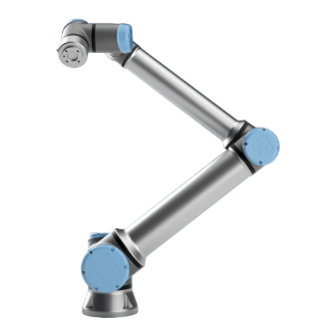
The joints, the base and the tool flange of the Robot Arm. With six joints and a wide scope of flexibility, Universal Robots e-Series collaborative robot arms are designed to mimic the range of motion of a human arm. Using our patented programming interface, PolyScope, it is easy to program the robot to move tools and communicate with other machines using electrical signals. - Page 13 1. Preface What Do the When you order a robot, you receive two boxes. One contains the Robot Arm, the other Boxes Contain contains: • Control Box with Teach Pendant • Mounting bracket for the Control Box • Mounting bracket for the Teach Pendant •...
- Page 14 Cases are handled either by your preferred distributor or escalated to Universal Robots Customer Service teams. On top of these features, it is also possible to subscribe to robot monitoring and manage additional user accounts in your company.
-
Page 15: Part I Hardware Installation Manual
Part I Hardware Installation Manual Part I Hardware Installation Manual User Manual UR10e... -
Page 16: Safety
Description This chapter contains important safety information, which must be read and understood by the integrator of Universal Robots e-Series robots before the robot is powered on for the first time. In this chapter, the first subsections are general. The later subsections contain specific engineering data relevant to enable setting up and programming the robot. -
Page 17: Validity And Responsibility
The integrators of Universal Robots e-Series robots are responsible for ensuring that the applicable safety laws and regulations in the country concerned are observed and that any significant hazards in the complete robot application are eliminated. -
Page 18: Safety Message Types
2. Safety 2.3. Safety Message Types Description Safety messages are used to emphasize important information. Read all the messages to help ensure safety and to prevent injury to personnel and product damage. The safety message types are defined below. WARNING Indicates a hazardous situation that, if not avoided, can result in death or serious injury. -
Page 19: General Warnings And Cautions
2. Safety 2.4. General Warnings and Cautions Description The following warnings, cautions and messages can be repeated, explained or detailed in different parts of this manual. WARNING Failure to adhere to the general safety practices, listed below, can result in injury. •... - Page 20 2. Safety WARNING: HOT SURFACE Prolonged contact with the heat generated by the robot arm and the Control Box, during operation, can lead to discomfort resulting in injury. • Do not handle or touch the robot while in operation or immediately after operation. •...
-
Page 21: Intended Use
• Read and follow the recommendations for intended use and the specifications provided in the User Manual. Universal Robots robots are intended for industrial use, to handle tools/end effectors and fixtures, or to process or transfer components or products. For details about the conditions under which the robot should operate, see Declarations and Certificates and the technical specifications. - Page 22 UNIVERSAL ROBOTS EXPRESSLY DISCLAIMS ANY EXPRESS OR IMPLIED WARRANTY OF FITNESS FOR ANY MISUSE. WARNING Avoid modifying the robot. A modification might create unforeseen hazards.
-
Page 23: Risk Assessment
2. Safety 2.6. Risk Assessment Description The risk assessment is a legal requirement, that shall be performed by a 3rd party integrator, or by the user of the UR robot in the role of integrator. The robot itself is partly completed machinery, as the safety of the robot installation depends on how the robot is integrated (E.g. - Page 24 (e.g. an enabling device to protect the operator during set-up and programming). Potential Universal Robots identifies the potential significant hazards listed below as hazards Hazards that must be considered by the integrator. Other significant hazards can be present in a specific robot installation.
-
Page 25: Pre-Use Assessment
2. Safety 2.7. Pre-Use Assessment Description The following tests must be conducted before using the robot for the first time or after any modifications are made. Verify that all safety input and output are appropriately and correctly connected. Test that all connected safety input and output, including devices common to multiple machines or robots, are functioning. -
Page 26: Emergency Stop
2. Safety 2.8. Emergency Stop Description The Emergency Stop or E-stop is the red push-button located on the Teach Pendant. Press the emergency stop push-button to stop all robot motion. Activating the emergency stop push-button causes a stop category one (IEC 60204-1). Emergency stops are not safeguards (ISO 12100). -
Page 27: Movement Without Drive Power
2. Safety 2.9. Movement Without Drive Power Description In the unlikely event of an emergency, when powering the robot is either impossible or unwanted, you can use forced back-driving to move the robot arm. To perform forced back-driving you must push, or pull, the robot arm hard to move the joint. -
Page 28: Safety-Related Functions And Interfaces
2.10. Safety-related Functions and Interfaces Description Universal Robots robots are equipped with a range of built-in safety functions as well as safety I/O, digital and analog control signals to or from the electrical interface, to connect to other machines and additional protective devices. Each safety function and I/O is constructed according to EN ISO13849-1 (see Certifications) with Performance Level d (PLd) using a category 3 architecture. -
Page 29: Stop Categories
*Stop the robot with power available to the drives, while maintaining the trajectory. Drive power is maintained after the robot is stopped. *Universal Robots robots’ Category 2 stops are further described as SS1 or as SS2 type stops according to IEC 61800-5-2. -
Page 30: Configurable Safety Functions
2.10.2. Configurable Safety Functions Description Universal Robots robot safety functions, as listed in the table below, are in the robot but are meant to control the robot system i.e. the robot with its attached tool/end effector. The robot safety functions are used to reduce robot system risks determined by the risk assessment. - Page 31 2. Safety Safety Function Accuracy Performance Level Category Emergency Stop – Safeguard Stop – Joint Position Limit 5 ° Joint Speed Limit 1.15 °/s Safety Planes 40 mm Tool Orientation 3 ° Speed Limit 50 mm/s Force Limit 25 N Momentum Limit 3 kg m/s Power Limit 10 W Stopping Time Limit 50 ms Stopping Distance Limit...
- Page 32 2. Safety Workspace 2.1: Due to the physical properties of the robot arm, certain workspace areas require attention regarding pinching hazards. One area (left) is defined for radial motions when the wrist 1 joint is at least 450 mm from the base of the robot. The other area (right) is within 200 mm of the base of the robot, when moving tangentially.
- Page 33 2. Safety Safety inputs The robot also has the following safety inputs: Safety Input Description Performs a Stop Category 1 (IEC 60204-1) informing other machines Emergency using the System Emergency Stop output, if that output is defined. A Stop Button stop is initiated in anything connected to the output. Robot Performs a Stop Category 1 (IEC 60204-1) via Control Box input, informing other machines using the System Emergency Stop output,...
-
Page 34: Safety Functions
2. Safety Safety outputs For interfacing with other machines, the robot is equipped with the following safety outputs: Safety Description Output System While this signal is logic low, the Robot Emergency Stop input is logic Emergency low or the Emergency Stop button is pressed. Stop Robot While this signal is logic high, no single joint of the robot moves more... -
Page 35: Safety Parameter Set
2. Safety 2.10.4. Safety Parameter Set Description The safety system has the following set of configurable safety parameters: • Normal • Reduced Normal and You can set up the safety limits for each set of safety parameters, creating distinct Reduced configurations for normal, or higher settings, and reduced. The reduced configuration is active when the tool/end effector is positioned on the reduced side of a Trigger Reduced Plane, or when the reduced configuration is externally triggered by a safety input. - Page 36 2. Safety Recovery When a safety limit is exceeded, the safety system must be restarted. For example, if a joint position limit is outside a safety limit, at start-up, Recovery is activated. You cannot run programs for the robot when recovery is activated, but the robot arm can be manually moved back within limits using Freedrive, or by using the Move tab in PolyScope.
-
Page 37: Modes
2. Safety 2.10.5. Modes Description When a safety limit is exceeded, the safety system must be restarted. For example, if a joint position limit is outside a safety limit, at start-up, Recovery is activated. You cannot run programs for the robot when recovery is activated, but the robot arm can be manually moved back within limits using Freedrive, or by using the Move tab in PolyScope. -
Page 38: Mechanical Interface
3. Mechanical Interface 3. Mechanical Interface Description The elements of the robot make up the robot system: Robot arm, tool or workpiece, Control Box and 3PE Teach Pendant are described in this chapter. You can also find maximum payload and workspace requirements. 3.1. Workspace and Operating Space Description The workspace is the range of the fully extended robot arm, horizontally and vertically. -
Page 39: Mounting Description
3. Mechanical Interface The cylindrical volume is both directly above and directly below the robot base. The robot extends 1300 mm from the base joint. Front Tilted 3.2. Mounting Description Description Robot arm Mounted with four 8.8 strength, 8.5 mm bolts and four M8 mounting (Base) holes at the base. -
Page 40: Securing The Robot Arm
3. Mechanical Interface Warning: WARNING Mounting Unstable mounting can lead to accidents. • Always make sure the robot parts are properly and securely mounted and bolted in place. 3.3. Securing the Robot Arm Description Surface on which the robot is fitted 0.05 0.030 8 FG8... -
Page 41: Securing Tool
3. Mechanical Interface To power down WARNING the robot arm Unexpected start-up and/or movement can lead to injury • Power down the robot arm to prevent unexpected start-up during mounting and dismounting. 1. Press the power button on the Teach Pendant to turn off the robot. 2. -
Page 42: Control Box Clearance
3. Mechanical Interface Tool flange The tool output flange (ISO 9409-1) is where the tool is mounted at the tip of the robot. It is recommended to use a radially slotted hole for the positioning pin to avoid over- constraining, while keeping precise position. CAUTION Very long M8 bolts can press against the bottom of the tool flange and short circuit the robot. - Page 43 3. Mechanical Interface User Manual UR10e...
-
Page 44: Maximum Payload
3. Mechanical Interface 3.6. Maximum Payload The rated payload of the Robot Arm depends on the center of gravity offset of the Description payload, see Figure 3 Mechanical Interface on page 38 The center of gravity offset is defined as the distance from the center of the tool flange to the center of gravity of the attached payload. - Page 45 3. Mechanical Interface Payload [kg] Center of gravity offset [mm] The relationship between the rated payload and the center of gravity offset. 2.3: Payload Inertia The robot can be used with high inertia payloads. The control software automatically adjusts accelerations, if you correctly enter the following in PolyScope (see:19.7.10 Set Payload on page 237 •...
-
Page 46: Electrical Interface
4. Electrical Interface 4. Electrical Interface Description The robot arm and the Control Box contain electrical interface groups. Examples are given for most types of I/O. The term I/O refers to both digital and analog control signals to or from the electrical interface groups listed below. •... - Page 47 • Make sure all equipment not rated for water exposure remain dry. If water is allowed to enter the product, lockout-tagout all power and then contact your local Universal Robots service provider for assistance. • Only use the original cables supplied with the robot only. Do not use the robot for applications where the cables are subject to flexing.
-
Page 48: Controller I/O
4. Electrical Interface 4.2. Controller I/O Description You can use the I/O inside the Control Box for a wide range of equipment including pneumatic relays, PLCs and emergency stop buttons. The illustration below shows the layout of electrical interface groups inside the Control Box. - Page 49 4. Electrical Interface Common This section defines electrical specifications for the following 24V digital I/O of the specifications for Control Box. all digital I/O • Safety I/O. • Configurable I/O. • General purpose I/O. NOTICE The word configurable is used for I/O configured as either safety- related I/O or normal I/O.
-
Page 50: Safety I/O
4. Electrical Interface Digital I/Os The digital I/O are constructed in compliance with IEC 61131-2. The electrical specifications are shown below. Terminals Parameter Unit Digital Outputs Current* [COx / DOx] [COx / DOx] Voltage drop [COx / DOx] Leakage current Function Type [COx / DOx]... - Page 51 4. Electrical Interface Table The functional difference is shown below. Emergency Safeguard 3PE Stop Stop Stop Robot stops moving Program execution Pauses Pauses Pauses Drive power Automatic or Automatic or Reset Manual manual manual Every cycle to Every cycle to Frequency of use Infrequent infrequent...
- Page 52 4. Electrical Interface Default safety The robot is delivered with a default configuration, which enables operation without any configuration additional safety equipment (see illustration below). Safety Connecting Most applications require one or more extra emergency stop buttons. The illustration emergency stop below shows how one or more emergency stop buttons can be connected.
- Page 53 4. Electrical Interface Safeguard stop This configuration is only intended for applications where the operator cannot go with automatic through the door and close it behind him. The configurable I/O is used to setup a reset resume button outside the door to reactivate robot motion. The robot resumes movement automatically when the signal is re-established.
-
Page 54: Three Position Enabling Device
Note: The two input channels for the Three-Position Enabling Device input have a disagreement tolerance of 1 second. NOTICE The Universal Robots e-Series safety system does not support multiple external Three-Position Enabling Devices. Operational Using a Three-Positon Enabling device requires the use of an Operational Mode switch. - Page 55 4. Electrical Interface User Manual UR10e...
-
Page 56: General Purpose Digital I/O
4. Electrical Interface 4.5. General Purpose Digital I/O Description The Startup screen contains settings for automatically loading and starting a default program, and for auto-initializing the Robot arm during power up. General purpose This section describes the general purpose 24V I/O (Gray terminals) and the digital I/O configurable I/O (Yellow terminals with black text) when not configured as safety I/O. -
Page 57: General Purpose Analog I/O
4. Electrical Interface 4.6. General Purpose Analog I/O Description The analog I/O interface is the green terminal. It is used to set or measure voltage (0- 10V) or current (4-20mA) to and from other equipment. The following directions is recommended to achieve the highest accuracy. •... -
Page 58: Remote On/Off Control
4. Electrical Interface Analog Output and Analog Analog Analog Input Power Power This example illustrates controlling a This example illustrates connecting conveyor belt with an analog speed an analog sensor. control input. 4.7. Remote ON/OFF Control Description Use remote ON/OFF control to turn the Control Box on and off without using the Teach Pendant. - Page 59 4. Electrical Interface Remote Remote This example illustrates connecting a This example illustrates connecting a remote ON button. remote OFF button. CAUTION Maintaining a press and hold on the power button switches the Control Box OFF without saving. • Do not press and hold the ON input or the POWER button without saving.
-
Page 60: Control Box Bracket
4. Electrical Interface 4.8. Control Box Bracket Description On the underside of the I/O interface groups, there is a bracket with ports that allows for additional connections (illustrated below). The base of the Control Box has a capped opening for easy connection (see Ethernet). The Mini Displayport supports monitors with Displayport and requires an active Mini Display to DVI or HDMI converter to connect monitors with DVI/HDMI interface. -
Page 61: Mains Connections
4. Electrical Interface To connect the Ethernet cable by passing it through the hole at the base of the Control Box, and plugging it into the Ethernet port on the underside of the bracket. Replace the cap at the base of the Control Box with an appropriate cable gland to connect the cable to the Ethernet port. - Page 62 4. Electrical Interface Mains To power the robot, the Control Box shall be connected to the mains via the supplied connections power cord. The IEC C13 connecter on the power cord connects to the IEC C14 appliance inlet at the bottom of the Control Box. NOTICE Always use a power cord with a country specific wall plug when connecting to the Control Box.
-
Page 63: Robot Connections: Robot Cable
4. Electrical Interface 4.11. Robot Connections: Robot Cable Description This subsection describes the connection for a robot arm configured with a fixed 6 meter Robot Cable. For information on connecting a robot arm configured with a Base Flange Cable connector, see 4.11 Robot Connections: Robot Cable above. -
Page 64: Robot Connections: Base Flange Cable
4. Electrical Interface 4.12. Robot Connections: Base Flange Cable Description This subsection describes the connection for a robot arm configured with a Base Flange Cable connector. For information on connecting a robot arm configured with a fixed 6 meter Robot Cable, see 4.12 Robot Connections: Base Flange Cable above. -
Page 65: Tool I/O
4. Electrical Interface 4.13. Tool I/O Description Adjacent to the tool flange on Wrist #3, there is an eight-pinned connector that provides power and control signals for different grippers and sensors that can be attached to the robot. The Lumberg RKMV 8-354 is a suitable industrial cable. Each of the eight wires inside the cable have different colors representing different functions. -
Page 66: Tool Power Supply
4. Electrical Interface 4.14. Tool Power Supply Description Access Tool I/O in the Installation Tab (see part Part II PolyScope Manual) to set the internal power supply to 0V, 12V or 24V. Dual Pin Power In Dual Pin Power mode, the output current can be increased as listed in (4.14 Tool Supply Power Supply above... -
Page 67: Tool Digital Outputs
4. Electrical Interface 4.15. Tool Digital Outputs Description Digital Outputs support three different modes: Mode Active Inactive Sinking (NPN) Open Sourcing (PNP) High Open Push / Pull High Access Tool I/O in the Installation Tab (see part Part II PolyScope Manual) to configure the output mode of each pin. -
Page 68: Tool Digital Inputs
4. Electrical Interface 4.16. Tool Digital Inputs Description The Startup screen contains settings for automatically loading and starting a default program, and for auto-initializing the Robot arm during power up. Table The Digital Inputs are implemented as PNP with weak pull-down resistors. This means that a floating input always reads as low. -
Page 69: Tool Communication I/O
4. Electrical Interface Caution CAUTION Analog Inputs are not protected against over voltage in current mode. Exceeding the limit in the electrical specification can cause permanent damage to the input. Using Tool This example shows an analog sensor connection with a non-differential output. The Analog Inputs, sensor output can be either current or voltage, as long as the input mode of that Analog Non-differential... -
Page 70: Transportation
Disclaimer Universal Robots cannot be held responsible for any damage caused by transportation of the equipment. You can see the recommendations for transportation without packaging at: myur.universal-robots.com/manuals... -
Page 71: Transport Without Packaging
5. Transportation 5.1. Transport Without Packaging Description Universal Robots always recommends transporting the robot in its original packaging. These recommendations are written to reduce unwanted vibrations in joints and brake systems and reduce joint rotation. If the robot is transported without its original packaging, then please refer to the following guidelines: •... -
Page 72: Maintenance And Repair
Client designated, trained individuals can also do repair work, provided they follow the inspection plan outlined in the Service Manual. See the Service Manual: Chapter 5 for full inspection plan for trained individuals All parts returned to Universal Robots shall be returned according to terms in the Service Manual. Safety for... -
Page 73: Cleaning
6. Maintenance and Repair 6.1. Cleaning Description Everyday cleaning You can wipe away any dust/dirt/oil observed on the robot arm using a cloth and one of the following cleaning agents: Water, Isopropyl alcohol, 10% Ethanol alcohol or 10% Naphtha. In rare cases, very small amounts of grease can be visible from the joint. This does not affect the function, use, or lifetime of the joint. -
Page 74: Robot Arm Visual Inspection
6. Maintenance and Repair 6.2.2. Robot Arm Visual Inspection Description NOTICE Using compressed air to clean the robot arm can damage the robot arm components. • Never use compressed air to clean the robot arm. Inspection points 1. Move the robot arm to the Zero position, if possible. 2. -
Page 75: Freedrive Inspection
6. Maintenance and Repair 6.2.3. Freedrive Inspection 1. Unmount any tool/s or attachment/s or set the TCP/Payload/CoG according to tool Inspection specifications. 2. To move the robot arm in Freedrive: • On the 3PE Teach Pendant, rapidly light-press, then light-press-and-hold the 3PE button. -
Page 76: Control Box Inspection Plan
6. Maintenance and Repair 6.2.4. Control Box Inspection Plan Description The table below is a checklist of the type of inspections recommended by Universal Robots. Perform inspections regularly, as advised in the list. Any listed parts found to be in an unacceptable state must be repaired or replaced. You can access the Service Manual (http://www.universal-robots.com/support) for more on how to perform inspections. -
Page 77: Disposal And Environment
2011/65/EU. These substances include mercury, cadmium, lead, chromium VI, polybrominated biphenyls and polybrominated diphenyl ethers. Fee for disposal and handling of electronic waste of Universal Robots e-Series robots sold on the Danish market is prepaid to DPA-system by Universal Robots A/S. -
Page 78: Certifications
Description Third party certification is voluntary. However, to provide the best service to robot integrators, Universal Robots chooses to certify its robots at the recognized test institutes listed below. You can find copies of all certificates in the chapter: Certificates. - Page 79 EU declarations. European directives are available on the directives official homepage: http://eur-lex.europa.eu. According to the Machinery Directive, Universal Robots’ robots are partly completed machines, as such a CE mark is not to be affixed. You can find the Declaration of Incorporation (DOI) according to the Machinery Directive in the chapter: Declarations and Certificates.
-
Page 80: Stopping Time And Stopping Distance
9. Stopping Time and Stopping Distance 9. Stopping Time and Stopping Distance Description You can set user-defined safety rated maximum stopping time and distance. If user-defined settings are used, the program speed is dynamically adjusted to always comply with the selected limits. The payload CoG is at the tool flange. - Page 81 9. Stopping Time and Stopping Distance Stopping distance in meters for maximum payload of 10kg Joint 0 (BASE) Stopping time in seconds for 33% of 10kg Stopping time in seconds for 66% of 10kg Stopping time in seconds for maximum payload of 10kg Joint 1 (SHOULDER)
- Page 82 9. Stopping Time and Stopping Distance Stopping distance in meters for 66% of 10kg Stopping distance in meters for maximum payload of 10kg Joint 1 (SHOULDER) Stopping time in seconds for 33% of 10kg Stopping time in seconds for 66% of 10kg Stopping time in seconds for maximum payload...
-
Page 83: Robot Scenario 2: 12.5 Kg
9. Stopping Time and Stopping Distance Joint 2 (ELBOW) Stopping distance in meters for all payloads Stopping time in seconds for all payloads 9.2. Robot Scenario 2: 12.5 kg. Joint 0 (BASE) Stopping distance in meters for 33% of 12.5kg Stopping distance in meters for 66% of 12.5kg User Manual... - Page 84 9. Stopping Time and Stopping Distance Stopping distance in meters for maximum payload of 12.5kg Joint 0 (BASE) Stopping time in seconds for 33% of 12.5kg Stopping time in seconds for 66% of 12.5kg Stopping time in seconds for maximum payload of 12.5kg UR10e User Manual...
- Page 85 9. Stopping Time and Stopping Distance Joint 1 (SHOULDER) Stopping distance in meters for 33% of 12.5kg Stopping distance in meters for 66% of 12.5kg Stopping distance in meters for maximum payload of 12.5kg Joint 1 (SHOULDER) Stopping time in seconds for 33% of 12.5kg User Manual UR10e...
- Page 86 9. Stopping Time and Stopping Distance Stopping time in seconds for 66% of 12.5kg Stopping time in seconds for maximum payload of 12.5kg Joint 2 (ELBOW) Stopping distance in meters for all payloads Stopping time in seconds for all payloads UR10e User Manual...
-
Page 87: Declarations And Certificates (Original En)
sequential numbering, restarting at 0 each year Incorporation: Universal Robots e-Series (UR3e, UR5e, UR10e and UR16e) shall only be put into service upon being integrated into a final complete machine (robot application or cell), which conforms with the provisions of the Machinery Directive and other applicable Directives. - Page 88 10. Declarations and Certificates (original EN) Reference to the harmonized standards used, as referred to in Article 7(2) of the MD & LV Directives and Article 6 of the EMC Directive: (I) EN ISO 10218-1:2011 TÜV (I) (II) EN 60204-1:2018 as (II) EN 60664-1:2007 (III) EN 61000-3- Nord Certificate # 44 708 applicable (II) EN...
-
Page 89: Warranty Information
11. Warranty Information 11. Warranty Information Product Warranty Direct your warranty inquiries to product related information on myUR User Manual Universal Robots A/S continues to improve the reliability and performance of its Disclaimer products, and as such reserves the right to upgrade products, and product documentation, without prior warning. -
Page 90: Certificates
12. Certificates 12. Certificates TÜV Rheinland UR10e User Manual... - Page 91 12. Certificates China RoHS Management Methods for Controlling Pollution by Electronic Information Products Product Declaration Table For Toxic or Hazardous Substances 表1 有毒有害物质或元素名称及含量标识格式 Product/Part Toxic and Hazardous Substances and Elements Name 有毒有害物质或元素 产品/部件名称 六价 多溴二苯醚 镉 汞 多溴联苯 铅 Hexavalent Polybrominated Mercury Cadmium Polybrominated Lead (Pb) Chromium diphenyl ethers (Hg) (Cd) biphenyls (PBB) (Cr+6) (PBDE) UR Robots 机器人:基本系统 UR3 / UR5 / UR10 / UR3e / UR5e / UR10e UR16e / UR20 / UR30 O: Indicates that this toxic or hazardous substance contained in all of the homogeneous materials for this part is below the limit requirement in SJ/T11363‐2006.
- Page 92 12. Certificates KC Safety UR10e User Manual...
- Page 93 12. Certificates KC Registration User Manual UR10e...
- Page 94 12. Certificates Environment Climatic and mechanical assessment Client Force Technology project no. Universal Robots A/S 117-32120 Energivej 25 5260 Odense S Denmark Product identification UR 3 robot arms UR 3 control boxes with attached Teach Pendants. UR 5 robot arms UR5 control boxes with attached Teach Pendants.
-
Page 95: Applied Standards
13. Applied Standards 13. Applied Standards Description This section describes relevant standards applied to the development and manufacturing of the UR robot, including the robot arm, Control Box and Teach Pendant . A standard is not a law, but a document developed by stakeholders within a given industry. - Page 96 Robot Systems English to American English, but the technical contents are the – Safety same. Part 2 of this standard is intended for the integrator of the Requirements robot system / robot application, and not Universal Robots. CAN/CSA-Z434 Clause Description Industrial...
- Page 97 13. Applied Standards IEC 61131-2 Clause Description Programmable controllers Both standard and safety-rated 24V I/Os comply with the Part 2: Equipment requirements of this standard to ensure reliable requirements and tests communication with other PLC systems. IEC 14118 Clause Description Safety of machinery – Safety requirements to prevent an unexpected start and Prevention of unexpected re-start, as a result of power loss or interruption of...
- Page 98 13. Applied Standards IEC 61140 Clause Description Protection against electric shock – A protective earth/ground connection is Common aspects for installation mandatory, as defined in the Part I Hardware and equipment Installation Manual. IEC 60068-2- Clause Description 1IEC 60068-2- Environmental testing Part 2-1: Tests - Test A: Cold Part 2-2: Tests - 2IEC 60068-2- Test B: Dry heat Part 2-27: Tests - Test Ea and guidance: Shock Part 27IEC 60068-2-...
-
Page 99: Technical Specifications
14. Technical Specifications 14. Technical Specifications Robot type UR10e Robot weight 33.3 kg / 73.5 lb Maximum payload 10 kg / 22 lb or 12.5 kg / 27.5 lb (3 Mechanical Interface on page 38) Reach 1300 mm / 51.2 in Joint ranges ± 360 ° for all joints Speed Base and Shoulder joints: Max 120 °/s. All other joints: Max 180 °/s . -
Page 100: Safety Functions Table
15. Safety Functions Table 1 15. Safety Functions Table 1 Description Universal Robots safety functions and safety I/O are PLd Category 3 (ISO 13849-1), where each safety function has a PFH value less than 1.8E-07. The PFH values are updated to include greater design flexibility for supply chain resilience. - Page 101 15. Safety Functions Table 1 SF2 Safeguard What Tolerance Description Affects Stop 4 (Robot happens? and PFH Stop according to This safety function is initiated by an ISO 10218-1) external protective device using safety inputs that initiate a Cat 2 stop .
- Page 102 15. Safety Functions Table 1 Joint Torque Exceeding the internal joint torque limit (each joint) results in a Cat 0 . This is not Limit accessible to the user; it is a factory setting. It is NOT shown as an e-Series safety function because there are no user settings and no user configurations.
- Page 103 15. Safety Functions Table 1 SF7 Force Limit What Tolerance Description Affects (TCP) happens? and PFH Will not allow The Force Limit is the force exerted by motion to the robot at the TCP (tool center point) exceed any and “elbow”. The safety function limit settings.
- Page 104 15. Safety Functions Table 1 SF10 UR Robot What Description Affects Estop Output Happens When configured for a Robot <Estop> output and there is a robot stop, the dual outputs are LOW. If there is no Robot <Estop> Stop initiated, dual outputs are high.
- Page 105 15. Safety Functions Table 1 SF12 UR Robot Description Affects Not stopping: When the robot is STOPPING (in process of stopping or in a Digital Output stand-still condition) the dual digital outputs are HIGH. External When outputs are LOW, robot is NOT in the process or connection stopping and NOT in a stand-still condition.
- Page 106 15. Safety Functions Table 1 SF15 Stopping What Tolerances Description Affects Time Limit happens? and PFH Real time monitoring of conditions such that the stopping time limit will not be exceeded. Robot speed is limited to ensure that the stop time limit is not Will not allow exceeded.
- Page 107 15. Safety Functions Table 1 SF17 Safe Home Tolerances Description What happens? Affects Position and PFH "monitored Safety function which monitors a position" safety rated output, such that it ensures that the output can only The “safe home External output” can only be activated when the robot is in connection TOL: 1.7 °...
- Page 108 15. Safety Functions Table 1 15.1. Table 1a Reduced Mode Description Affects SF parameter Reduced Mode can be initiated by a safety plane/ boundary settings change (starts at 2cm of the plane and reduced mode settings are achieved within 2cm of the plane) or by use of an input to initiate (will achieve reduced settings within 500ms).
-
Page 109: Table
15. Safety Functions Table 1 Mode switch Description Affects INPUT When the external connections are Low, Operation Mode (running/ automatic operation in automatic mode) is in effect. When High, mode is programming/ teach. Recommendation: Less Use with an enabling device, for example a UR e-Series than Teach Pendant with an integrated 3-position enabling device. - Page 110 15. Safety Functions Table 1 Collaborative Technique Explanation UR e-Series Operation 2011 This is essentially individual edition, clause and direct personal control 5.10.3 while the robot is in automatic mode. Hand guiding equipment shall be located close to the end- UR robots do not provide hand- effector and shall have: guiding for collaborative operation.
- Page 111 15. Safety Functions Table 1 Collaborative Technique Explanation UR e-Series Operation 2011 SSM is the robot edition, clause maintaining a separation 5.10.4 distance from any operator (human). This is done by monitoring of the distance between the robot system and intrusions to ensure that the MINIMUM PROTECTIVE DISTANCE is assured.
- Page 112 15. Safety Functions Table 1 Collaborative Technique Explanation UR e-Series Operation 2011 UR robots are power and force edition, clause How to accomplish PFL is left to the limiting robots specifically 5.10.5 robot manufacturer. The robot designed to enable design and/or safety functions will collaborative applications limit the energy transfer from the where the robot could contact a...
-
Page 113: Part Ii Polyscope Manual
Part II PolyScope Manual Part II PolyScope Manual User Manual UR10e... - Page 114 Part II PolyScope Manual UR10e User Manual...
-
Page 115: Introduction
16.1. Robot Arm Basics Description The Universal Robots robot arm is composed of tubes and joints. You use the PolyScope to coordinate the motion of these joints to move the robot arm. You attach tools to end of the robot arm, or Tool Flange . Moving the robot arm positions the tool. -
Page 116: Robot Arm Installation
16.2. Robot Arm Installation Description Install and power on the robot arm and Control Box to start using PolyScope. See Hardware Installation Manual for detailed installation instructions. Install the robot You have to assemble the robot arm, Control Box and Teach Pendant to be able to continue. - Page 117 1. On your Teach Pendant, press the power button to turn on the control box. 2. Wait as text from the underlying operating system, followed by buttons, appear on the screen. 3. A Getting Started screen can appear, prompting you to begin programming the robot.
- Page 118 Start up You have to start the robot. This disengages the braking system, and makes the robot able to engage freedrive. CAUTION Failure to verify the payload and installation before starting up the robot arm can lead to injury to personnel and/or property damage. •...
- Page 119 User Manual UR10e...
-
Page 120: Polyscope Overview
16.3. PolyScope Overview Description PolyScope is the Graphical User Interface (GUI) on the Teach Pendant that operates the robot arm via a touch screen. You create, load and execute programs for the robot in PolyScope. The PolyScope interface is divided as shown in the following illustration: •... -
Page 121: Icons/Tabs On Polyscope
16.3.1. Icons/Tabs On PolyScope Description The following section lists and defines the icons/tabs and buttons in the PolyScope interface. Header Icons / Functions Run is a simple means of operating the robot using pre-written programs. Program creates and/or modifies robot programs. Installation configures robot arm settings and external equipment e.g. - Page 122 Local indicates the robot can be controlled locally. Tap it to switch to Remote control. Remote indicates the robot can be controlled from a remote location. Tap it to switch to Local control. Safety Checksum displays the active safety configuration. Hamburger Menu accesses PolyScope Help, About and Settings.
-
Page 123: Freedrive
16.4. Freedrive Description Freedrive allows the robot arm to be manually pulled into desired positions and/or poses. The joints move with little resistance because the brakes are released. While the robot arm is being moved manually, it is in Freedrive (see Operational mode on page 134). - Page 124 Freedrive on To use Freedrive on robot to freedrive the robot arm: robot 1. Press-and-hold the button of switch configured for Freedrive on robot. 2. When the Freedrive panel appears in PolyScope, select the desired movement type for the robot arm’s joints. Or use the list of axes to customize the movement type.
-
Page 125: Freedrive Panel
16.4.1. Freedrive Panel Description When the robot arm is in Freedrive, a panel appears on PolyScope, as illustrated below. LED Freedrive The LED on the status bar of the Freedrive panel indicates: panel • When one or more joints are approaching their joint limits. •... -
Page 126: Backdrive
Movement is allowed through all axes. All axes are free Movement is only allowed through the X-axis and Y-axis. Plane Movement is allowed through all axes, without rotation. Translation Movement is allowed through all axes, in a spherical motion, around the TCP. Rotation CAUTION Moving the robot arm in some axes when a tool is attached, can... - Page 127 3PE Teach To use the 3PE TP button to backdrive the robot arm. Pendant 1. On the Initialize screen, tap ON to start the power up sequence. 2. When the robot state is Teach Pendant 3PE Stop, light-press, then light-press- and-hold, the 3PE TP button.
-
Page 128: Backdrive Inspection
16.5.1. Backdrive Inspection Description If the robot is close to colliding with something, you can use Backdrive to move the robot arm to a safe position before initializing. 3PE Teach Pendant UR10e User Manual... - Page 129 1. Press ON to enable power. Status changes to Robot Active Enable Backdrive 2. Press and hold Freedrive. Status changes to Backdrive 3. Move robot as in Freedrive mode. Joint brakes are released where needed once the Freedrive button is activated. NOTICE In Backdrive Mode the robot is “heavy”...
-
Page 130: Quick System Start-Up
9. Tap the Start button, for the robot to release its brake system. The robot vibrates and makes clicking sounds indicating it is ready to be programmed. NOTICE Learn to program your Universal Robots robot on www.universal- robots.com/academy/ UR10e User Manual... -
Page 131: The First Program
16.7. The First Program Description A program is a list of commands telling the robot what to do. For most tasks, programming is done entirely using the PolyScope software. PolyScope allows you to teach the robot arm how to move using a series of waypoints to set up a path for the robot arm to follow. - Page 132 1. On PolyScope, in the Header File Path, tap New... and select Program. To create a simple program 2. Under Basic, tap Waypoint to add a waypoint to the program tree. A default MoveJ is also added to the program tree. 3.
-
Page 133: Robot Cyber Security
Before your system can reach a secure state of operation, ensure the following: Pre-requisites • You have a thourough understanding of general cyber security principles and advanced technologies as used in your Universal Robots robot. • You take physical security measures to allow only trusted personnel physical access to the robot. -
Page 134: Operational Mode Selection
16.9. Operational Mode Selection Description Operational Modes are enabled when you configure a Three-Position Enabling Device, set a password, define an Operational Mode Configurable I/O, or via the Dasboard Server. (see Using the Dashboard Server on page 136) You can set the robot in automatic mode and in manual mode: Automatic Mode Once activated, the robot can only perform pre-defined tasks. - Page 135 Notice when NOTICE switching mode • A Universal Robots robot may not be equipped with a Three- Position Enabling Device. If the risk assessment requires the device, it must be attached before the robot is used. • If a Three-Position Enabling Device is not configured, speed is not reduced in Manual Mode.
- Page 136 1. Connect to the Dashboard server. Using the Dashboard Server 2. Use the Set Operational Mode commands. • Set Operational Mode Automatic • Set Operational Mode Manual • Clear Operational Mode http://universal-robots.com/support/ for more on using the Dashboard server. Three-Position When a Three-Position Enabling Device is configured and the Operational Mode is in Enabling Device Manual Mode, the robot can only be moved by pressing the Three-Position Enabling...
-
Page 137: Software Safety Configuration
17. Software Safety Configuration 17. Software Safety Configuration Description This section covers how to access the robot safety settings. It is made up of items that help you set up the robot Safety Configuration. WARNING Before you configure your robot safety settings, your integrator must conduct a risk assessment to guarantee the safety of personnel and equipment around the robot. - Page 138 17. Software Safety Configuration Accessing Safety Settings are password protected and can only be configured once a password is Software Safety set and subsequently used. To access the software safety settings Settings 1. In your PolyScope header, tap the Installation icon. 2.
-
Page 139: Setting A Software Safety Password
17.1. Setting a Software Safety Password Description You must set a password to Unlock all safety settings that make up your Safety Configuration. If no safety password is applied, you are prompted to set it up. To set a Software You can tap the Lock tab to lock all Safety settings again or simply navigate to a screen Safety password outside of the Safety menu. -
Page 140: Changing The Software Safety Configuration
17.2. Changing the Software Safety Configuration Description Changes to the Safety Configuration settings must comply with the risk assessment conducted by the integrator (see Hardware Installation Manual). Recommended To change the safety configuration procedure for the integrator: 1. Verify that changes comply with the risk assessment conducted by the integrator. -
Page 141: Applying A New Software Safety Configuration
17.3. Applying a New Software Safety Configuration Description The robot is powered off while you make changes to the configuration. Your changes only take effect after you tap the Apply button. The robot cannot be powered on again until you select Apply and Restart to visually inspect your robot Safety Configuration which, for safety reasons, is displayed in SI Units in a popup. - Page 142 UR10e User Manual...
-
Page 143: Safety Configuration Without Teach Pendant
17.4. Safety Configuration without Teach Pendant Description You can use the robot without attaching the Teach Pendant. Removing the Teach Pendant requires defining another Emergency Stop source. You must specify if the Teach Pendant is attached to avoid triggering a safety violation. CAUTION If the Teach Pendant is detached or disconnected from the robot, the Emergency Stop button is no longer active. -
Page 144: Software Safety Limits
Description Under normal conditions, i.e. when no robot stop is in effect, the safety system operates in a Safety Mode associated with a set of safety limits: • Normal mode is the safety mode that is active by default • Reduced mode is active when the robot Tool Center Point (TCP) is positioned beyond a Trigger Reduced mode plane (see 17.8 Software Safety Restrictions on... - Page 145 Factory Presets Factory Presets is where you can use the slider to select a predefined safety setting . The values in the table are updated to reflect the preset values ranging from Most Restricted to Least Restricted NOTICE Slider values are only suggestions and do not substitute a proper risk assessment.
-
Page 146: Joint Limits
Tool Speed limits maximum robot tool speed. Tool Force limits the maximum force exerted by the robot tool in clamping situations. Limited to 400N. Elbow Speed limits maximum robot elbow speed. Elbow Force limits maximum force that the elbow exerts on the environment. Limited to 400 N. The tool speed and force are limited at the tool flange and the center of the two user- defined tool positions, (see 17.8.2 Tool Position Restriction on... - Page 147 Description Joint Limits allow you to restrict individual robot joint movements in joint space i.e. joint rotational position and joint rotational speed. There are two Joint Limits options: Maximum speed and Position range. User Manual UR10e...
- Page 148 UR10e User Manual...
-
Page 149: Safety I/O
17.7. Safety I/O Description The I/O are divided between inputs and outputs and are paired up so that each function provides a Category 3 and PLd I/O. Input Signals The following Safety Functions can be used with the input signals: System Emergency Stop This is an emergency stop button alternative to the one on the Teach Pendant, providing the same functionality if the device complies with ISO 13850. - Page 150 Input Signals Operational Mode When defined, this input can be used to switch between Automatic Mode and Manual Mode (see Operational mode on page 134). Safeguard Reset When a Safeguard Stop occurs, this output ensures that the Safeguard Stop state continues until a reset is triggered. Automatic Mode Safeguard Stop Once configured, an Automatic Mode Safeguard Stop performs a Safeguard Stop when the input pins are low and ONLY when the robot is in Automatic mode.
- Page 151 Output Signals You can apply the following Safety functions for output signals. All signals return to low when the state which triggered the high signal has ended: System Emergency Stop Signal is Low when the safety system has been triggered into an Emergency Stopped state by the Robot Emergency Stop input or the Emergency Stop Button.
- Page 152 OSSD Safety You can configure the Control Box to output OSSD pulses when a safety output is Signals inactive/high. OSSD pulses detect the ability of the Control Box to make safety outputs active/low. When OSSD pulses are enabled for an output, a 1ms low pulse is generated on the safety output once every 32ms.
-
Page 153: Software Safety Restrictions
17.8. Software Safety Restrictions Description NOTICE Configuring planes is entirely based on features. We recommend you create and name all features before editing the safety configuration, as the robot is powered off once the Safety Tab has been unlocked and moving the robot will be impossible. Safety planes restrict robot workspace. - Page 154 Safety You can configure each plane with restrictive Modes using the icons listed below. PlanesModes Disabled The safety plane is never active in this state. Normal When the safety system is in Normal mode, a normal plane is active and it acts as a strict limit on the position.
- Page 155 Copy Feature In Copy Feature, only Undefined and Base are available. You can reset a configured safety plane by selecting Undefined If the copied feature is modified in the Features screen, a warning icon appears to the right of the Copy Feature text. This indicates that the feature is out of sync i.e. the information in the properties card is not updated to reflect the modifications that may have been made to the Feature.
- Page 156 Color Codes Gray Plane is configured but disabled (A) Yellow & Black Normal Plane (B) Blue & Green Trigger Plane (C) Black Arrow The side of the plane the tool and/or elbow is allowed to be on (For Normal Planes) Green Arrow The side of the plane the tool and/or elbow is allowed to be on (For Trigger Planes) Gray Arrow...
- Page 157 Elbow Restriction You can enable Restrict Elbow to prevent robot elbow joint from passing through any of your defined planes. Disable Restrict Elbow for elbow to pass through planes. The diameter of the ball that restricts the elbow is different for each size of robot. UR3e 0.1 m UR5e...
- Page 158 Adding a plane Displacement offsets the plane in either the positive or negative direction along the feature example plane normal (Z-axis of the plane feature). Deselect the checkbox for the Elbow and the Tool Flange so they do not trigger the safety plane.
- Page 159 Tool flange In this example, an X-Y-plane is created with an offset of 300mm along the positive Z- restriction axis with reference to the base feature. The Z-axis of the plane can be thought of as “pointing” towards the restricted area. example If the safety plane is needed on e.g., the surface of a table, rotate the plane 3.142 rad or 180°...
- Page 160 UR10e User Manual...
-
Page 161: Tool Direction Restriction
17.8.1. Tool Direction Restriction Description The Tool Direction screen can be used to restrict the angle in which the tool is pointing. The limit is defined by a cone that has a fixed orientation with respect to the robot arm Base. - Page 162 Limit Properties The Tool Direction limit has three configurable properties: 1. Cone center: You can select a point or plane feature from the drop-down menu, to define the center of the cone. The Z axis of the selected feature is used as the direction around which the cone is centred.
-
Page 163: Tool Position Restriction
17.8.2. Tool Position Restriction Description The Tool Position screen enables more controlled restriction of tools and/or accessories placed on the end of the robot arm. • Robot is where you can visualize your modifications. • Tool is where you can define and configure a tool up to two tools. •... - Page 164 User defined For the user defined tools, the user can change: tools • Radius to change the radius of the tool sphere. The radius is considered when using safety planes. When a point in the sphere passes a reduced mode trigger plane, the robot switches to Reduced mode.
- Page 165 Tool Position You must set a Tool Position within the safety settings, for the safety plane to trigger Warning correctly when the tool TCP approaches the safety plane. The warning remains on the Tool Position if: • You fail to add a new tool under Tool Flange. To configure the tool position 1.
- Page 166 Tool Position In this example, a Radius of 0.8mm is set and the TCP position to XYZ [20, 0, 400] in Warning example millimeters respectively. Optionally you can choose to ”Copy TCP” by using the drop- down menu if one has already been set in the ->General/TCP settings. Once the Apply is tapped in the bottom right corner of the screen, you are DONE.
-
Page 167: Safe Home Position
17.9. Safe Home Position Description Safe Home is a return position defined by using the user-defined Home Position. Safe Home I/Os are active when the Robot Arm is in the Safe Home Position and a Safe Home I/O is defined. The Robot Arm is in the Safe Home Position if the joint positions are at the specified joint angles or a multiple of 360 degrees thereof. - Page 168 Editing Safe To edit Safe Home Editing Home does not automatically modify a previously defined Safe Home position. Home While these values are out of sync, Home program node is undefined. 1. In the Header, tap Installation. 2. In the Side Menu on the left of the screen, under General, select Home. 3.
-
Page 169: Run Tab
18. Run Tab 18. Run Tab Description The Run tab allows you to do simple operations and monitor the state of your robot. You can load, play, pause and stop a program, as well as monitor variables. The Run Tab is most useful when the program is created and the robot is ready for operation. Program: The Program pane displays the name and status of the current program. - Page 170 18. Run Tab Variable You can add information to your variables by adding variable descriptions in the descriptions Description column. You can use the variable descriptions to convey the purpose of the variable and/or the meaning of its value to operators using the Run tab screen and/or other programmers.
- Page 171 18. Run Tab Collapsed Description column Expanded Description column Control The Control pane allows you to control the running program. You can play and stop, or pause and resume a program, using the buttons listed in the table below: • The Play button, Pause button and the Resume Button are combined. •...
-
Page 172: Move Robot Into Position
18. Run Tab To play a program Play 1. Under Control, tap Play to start running a program from the beginning. To resume a paused program Resume 1. Tap Resume to continue running the paused program. To stop a program 1. Tap Stop to stop the running program Stop •... -
Page 173: Program
18. Run Tab Move robot to Hold down Move robot to: to move the Robot Arm to a start position. The animated Robot Arm displayed on-screen shows the desired movement about to be performed. NOTICE Collision can damage the robot or other equipment. Compare the animation with the position of the real Robot Arm to ensure the Robot Arm can safely perform the movement without colliding with any obstacles. - Page 174 18. Run Tab string A sequence of characters. A vector describing the location and orientation in Cartesian space. It is a pose combination of a position vector ( x , y , z ) and a rotation vector ( rx , ry , rz ) representing the orientation, written p[x, y, z, rx, ry, rz].
-
Page 175: Program Tab
19. Program Tab 19. Program Tab Description The Program tab is the where you create and edit robot programs The Program tab consists of two main areas; the left side contains the program nodes you can add to your robot program, and the right side contains the configuration of the program nodes you can add to your program. - Page 176 19. Program Tab Program Robot programs often become quite long, so order to be able to see the flow of the robot Execution program, you can look at what program node is active. Indication When the program is running, the program node currently being executed is indicated by a small icon next to that node.
-
Page 177: Robot Program Configuration
19.1. Robot Program Configuration Description It is possible to create a configuration for the entire robot program. This type of configuration does not affect individual program nodes, it gives the entire robot program important behavior. • You can add instructions to be executed before the robot program is started. •... - Page 178 Set Initial Select this to set initial values of program variables. Variable Value 1. Select a variable from the drop down list, or use the variable selector box. 2. Enter an expression for that variable. This expression is used to set the variable value at program start.
-
Page 179: Program Tree Toolbar
19.2. Program Tree Toolbar Description You can work with the program nodes that have been added to the program tree by using the icons in the bottom of the program tree. Icons in the Program Tree Use the toolbar at the base of the Program Tree to modify the Program Tree. toolbar Undo &... - Page 180 Description The Variable Setup is always the first node on the program tree. The Variable Setup pane is where you name and edit program variables, and designate them as favorites. Designating a favorite variable displays it on the Variable pane in the Program tab screen and on the Run tab screen.
- Page 181 Initial value An initial value is the first value you assign to a program variable, when you start a program. You can check the Keep value from previous run box to replace the initial value with a value from a previously run program. However, if you load a new program, after using a value from a previously run program, the initial value is reinstated.
-
Page 182: Command Tab
19.2.2. Command Tab Description The Command tab in the Program Tab contains the configuration options for the selected program node. These configuration options appear under the Command Tab on the right side of the screen. The Command tab's pane changes when you select each different program node, on the left side of the screen. - Page 183 Wait Command The Wait command is another often used program node. Example You can use the Wait command to make the robot program wait for a signal from a sensor that is attached to the control box. Palletizing You can use the palletizing template to quickly create a palletizing program. The same palletizing program is also used to create a depalletizing program.
- Page 184 You can add the If command the program tree to add "If", "Else" and "ElseIf" conditions to a robot program. Example You can use the If command to create two different results for a robot program. UR10e User Manual...
-
Page 185: Graphics Tab
19.2.3. Graphics Tab Description The Graphics tab in the Program Tab provides a graphical representation of the running program. The graphical representation appears in the pane under the Graphics tab on the right side of the screen. The buttons in the top-right side of the pane can disable the various graphics in 3D view. - Page 186 Trigger Planes Trigger planes appear in the 3D view in blue and green. A small arrow points to the side of the plane, where the Normal mode limits (see 17.5 Software Safety Modes on page 143) are active. The tool orientation boundary limit is visualized with a spherical cone together with a vector indicating the current orientation of the robot tool.
-
Page 187: Variables Tab
19.2.4. Variables Tab Description The Variables tab in the Program Tab shows the live values of variables in the running program. The variables appear as a list in the pane under the Variables tab on the right side of the screen. Variables only appear when there is information to display and remain visible between program runs. -
Page 188: Expression Editor
Variable Value A robot program uses variables to store and update various values during runtime. Types Variables only appear when there is information to display. Variable types include: • Program variables - These are available to the running program only and their values are lost as soon as the program is stopped. -
Page 189: Starting A Program From A Selected Program Node
Expressions in The expression is checked for grammatical errors when the Ok button is pressed. The Editor Cancel button leaves the screen, discarding all changes. An expression can look like this: digital_in[1] True and analog_in[0]<0.5 19.4. Starting a Program from a Selected Program Node Description You can start your robot program from any program node in the program tree. -
Page 190: Using Breakpoints In A Program
Play From The Play button in the Footer provides options for how to start the program. Here you can see the Play button is selected and the Play from Selection is displayed. Selection NOTICE • A program can only start from a node in the robot Program tree. •... - Page 191 Description A breakpoint pauses program execution. You can use breakpoints to pause and resume a running program at a specific point. This is useful when you are inspecting robot position, variables, etc. (See Operational mode on page 134). Here you can see a breakpoint added to a node: When the robot program reaches a breakpoint, it will turn red, and other upcoming breakpoints are still blue.
- Page 192 Add a Breakpoint To add a breakpoint to a program 1. In a Program tree, tap a line number to add a breakpoint. 2. The breakpoint is active until you clear the breakpoint from the robot program. Clear a To clear a breakpoint in a program Breakpoint 1.
-
Page 193: Single Step In A Program
19.6. Single Step in a Program Description Single Step allows the current program to be exectued one node at a time, when the robot is in Manual mode. (See Operational mode on page 134). This is useful when you are checking your program for errors. Single Step Single Step allows the selected program node to run, then pauses at the beginning of a new node. - Page 194 UR10e User Manual...
-
Page 195: Basic Program Nodes
19.7. Basic program nodes Description Basic program nodes are used to create simple robot applications. Some basic program nodes are also used to organize your robot program and create comments in your robot program. This can be quite useful, if it is large robot program. 19.7.1. - Page 196 1. In your robot program, select the place where you wish to add a Move. Add a MoveJ command 2. Under Basic, tap Move to add a waypoint to the robot program together with a Move node. 3. Select the move node. 4.
- Page 197 Detail MoveP moves the tool linearly with constant speed with circular blends, and is intended for some process operations, like gluing or dispensing. The size of the blend radius is by default a shared value between all the waypoints. A smaller value will make the path turn sharper whereas a higher value will make the path smoother.
- Page 198 Description The different feature options in the Move pane allow you to add detail to a Move and the attached waypoint/s. Use these options to customize your program See the Move pane features below: Move: Set TCP Use this setting, if you need to change TCP during the robot program execution. This is useful if you need to manipulate different objects in the robot program.
-
Page 199: Waypoints
Move: Use joint You can use the Use joint angles as an alternative to the 3D pose when you are using angles MoveJ to define a waypoint. Waypoints defined using the Use joint angle are not changed when a program is moved between robots. - Page 200 1. In your Robot Program, select the place where you wish to add a Move. Add a waypoint to a robot 2. Under Basic, tap Move. program A waypoint is added to the robot program together with the Move node. 1.
- Page 201 Detail Using a waypoint means applying the taught relationship between the feature and the TCP from the Move command. The relationship between the feature and the TCP, applied to the current selected feature, achieves the desired TCP location. The robot calculates how to position the arm to allow the current active TCP to reach the desired TCP position.
- Page 202 Linking By selecting the link icon, waypoints are linked and share position information. Waypoints Detail Other waypoint information such as blend radius, tool/joint speed and tool/joint acceleration is configured for individual waypoints even though they may be linked. Stop at this point You configure the robot program to stop at this waypoint.
- Page 203 Joint Speed / You can modify the speed and acceleration of joints for each waypoint in a Move Acceleration command. 1. Select the waypoint you wish to modify Modify joint speed or 2. On the right side of the screen, set the joint speed or acceleration by selecting acceleration 3.
- Page 204 Steps Please see the link Add Until on page 217 for step by step instructions. Fixed Waypoint Description A fixed waypoint is the standard waypoint used in PolyScope. It is a fixed location, relative to a set coordinate system (the robot’s base by default), that the robot will move back to when prompted.
- Page 205 To add a fixed waypoint to a robot program 1. In the Program tab, tap Basic. 2. Add a move command 3. Select the automatically generated waypoint a. Notice the selector is automatically set to 4. Tap to access the Move tab 5.
- Page 206 Setting a Fixed Waypoint To add a fixed waypoint to a robot program 1. In your Robot Program, select the place or node where you wish to add a fixed waypoint. 2. Under Basic, tap Waypoint. 3. Select your newly added waypoint in the robot program. 4.
- Page 207 Relative Waypoint Description A relative waypoint is created by defining two waypoints. These two waypoints determine the distance and direction the relative waypoint should move The relative waypoint can be defined to the robot arm’s previous position, such as “two centimeters to the left”.
- Page 208 1. In the Program tab, select the Basic menu Add a relative waypoint to a 2. Tap Waypoint robot program a. Notice the selector is automatically set to Fixed position b. Change the waypoint to Relative position. 3. Set the first waypoint (from point...) 4.
- Page 209 Variable Waypoint Description A variable waypoint moves to a position determined by a variable in PolyScope. The variable must be in the pose URScript format, p[x, y, z, rx, ry, rz], allowing a single waypoint in the Program Tree to be updated by changing the X, Y, Z, RX, RY, or RZ value without manually resetting the waypoint.
- Page 210 Detail A waypoint with the position given by a variable, in this case calculated_pose . The variable has to be a pose such as var=p[0.5,0.0,0.0,3.14,0.0,0.0]. The first three are x,y,z and the last three are the orientation given as a rotation vector given by the vector rx,ry,rz .
- Page 211 Example: The robot starts at waypoint 1 (WP_1), and it needs to pick up an object at waypoint 3 Blending in a pick (WP_3). To avoid collisions with the object and other obstacles , the robot must avoid (O) by and place using waypoint 2 (WP_2).
- Page 212 Description Blending enables the robot to smoothly transition between two trajectories, without stopping at the waypoint between them. Blending makes your robot program run faster because, when you create a smooth transition between trajectories, you avoid slowing down an acceleration between trajectories.
- Page 213 If a blend radius is set, the robot arm trajectory blends around the waypoint, allowing the robot arm not to stop at the point. Blends cannot overlap, so it is not possible to set a blend radius that overlaps with the blend radius of a previous or following waypoint.
- Page 214 Blend Trajectories Description Blending enables the robot to smoothly transition between two trajectories, without stopping at the waypoint between them. Blending makes your robot program run faster because, when you create a smooth transition between trajectories, you avoid slowing down an acceleration between trajectories.
- Page 215 Depending on the movement type (i.e., MoveL, MoveJ, or MoveP), different blend trajectories are generated. • Blends in MoveP When blending in MoveP, the position of the blend follows a circle arc at constant speed. The orientation blends with a smooth interpolation between the two trajectories.
- Page 216 Conditional blend This example is a very situational example, but it shows that the robot program may in a trajectories very rare situations calculate program nodes before execution. The blend trajectory is affected both by the waypoint where the blend radius is set and the following one in the program tree.
- Page 217 Add Until Description The program node Until defines stop criteria for a motion. You can add Until nodes from Direction and Waypoint commands. You can only add a direction node to a MoveL and MoveP. The robot moves along a path and stops when contact is detected. You can add multiple stop criteria to a single movement.
- Page 218 1. When you have added the Until command, tap the Add an Until expression to a robot program 2. Tap the yellow expression field 3. Add the expression with the keyboard 4. Tap Submit to save the expression 5. Choose if you want to use the shared deceleration or a custom deceleration Distance This node stops a Direction move when the robot moves a certain distance.
- Page 219 Tool Contact This node allows the robot to stop motion when contact with the tool is established. You can use this node to stop a movement when the robot tool detects a contact. You can also define the deceleration of the stop and the retraction of the tool. Example You can use the Until Tool Contact Node for applications like Stacking/Destacking, where Until Tool Contact determines the height of stacked objects.
- Page 220 1. When you have added the Until command, tap the Add a Until tool contact to a robot program CAUTION The default speed of motion is too high for contact detection. A faster speed of motion triggers a robot stop, before the Tool Contact condition can take effect.
- Page 221 1. When you have added the Until command, tap the add a No Action to a robot program 2. Select the analogue or digital input 3. Add additional configuration Add Action This node allows you to add a program node if a specific Until condition is met. You can also add an additional action to be executed right after an Until command.
-
Page 222: Direction
19.7.3. Direction Description The Direction command specifies a motion relative to feature axes or TCPs. The robot moves in the path specified by the Direction program node until that movement is stopped by an Add Until on page 217 condition. Direction The Direction command allows you to make the robot move in a specific direction. - Page 223 1. In your robot program, select the place or node where you wish to add a Add a Direction Direction command. movement to a robot program 2. Under Basic, tap Direction to add a linear movement to your Program Tree. 3.
-
Page 224: Wait
In the Direction field, tap the Add Until button to define and add stop criteria to your Program Tree. Direction Vector The Direction Vector settings allow you to define the vector direction for linear motion. Use the Tool Speed and Tool Acceleration for the following: •... - Page 225 1. In your Robot Program, select the place or node where you wish to add a Wait command. 2. Under Basic, tap Wait. 3. On the right side of the screen, tap the No wait selector. The No Wait command can be used a temporary placeholder be used, when you are programming your robot program.
- Page 226 1. In your Robot Program, select the place or node where you wish to add a Wait command. 2. Under Basic, tap Wait. 3. Tap the Wait x seconds selector. 4. Tap the number box to select a value that determines the length of the Wait. 1.
- Page 227 1. In your Robot Program, select the place or node where you wish to add a Wait Add a Wait for command. digital input to a robot program 2. Under Basic, tap Wait. 3. Tap the Wait for Digital Input selector. More definition is required for this Wait type.
- Page 228 1. In your Robot Program, select the place or node where you wish to add a Wait Add a Wait for command. analog input to a robot program 2. Under Basic, tap Wait. 3. Tap the Wait for analog input selector. 4.
-
Page 229: Set
Example: Wait You can add a wait command with an expression that waits for two or more conditions for f to be true or false depending on configuration when using a machine and a conveyor (x) expression sensor. Both the machine and the conveyor become ready for the robot. 19.7.5. - Page 230 1. In your Robot Program, select the place or node where you wish to add a Set command. 2. Under Basic, tap Set. 3. Select Set Digital Output 4. Select your pre-named digital output (See 20.4 I/O Setup on page 285) 5. Set to High/Low Example: Set Use this Set command, if you want a conveyor to start or stop moving.
-
Page 231: Popup
Example: Set In order to ensure valid communication with older machinery, you can set a pulse to a single pulse high command for a duration, so that you ensure that the older machinery has time to register the command. Increment installation This is used to increase the number of a counter variable. - Page 232 Description The Popup is a message that appears on the screen when the program reaches the Popup node in the program tree. Popup messages are limited to a maximum of 255 characters. You can choose to use different popup message types. •...
- Page 233 User Manual UR10e...
-
Page 234: Halt
19.7.7. Halt Description The Halt command allows you to stop the robot at a specific node in the robot program. It is the equivalent of pressing the STOP button. You must restart the program after the halt command. When you add a Halt to your robot program, the Halt pane appears to the right of the screen. -
Page 235: Comment
19.7.8. Comment Description The Comment command allows you to keep track of decisions you make while you create or update your robot program. You can add comments directly inside a robot program used by different users. When you add a Comment to your robot program, the Comment pane appears to the right of the screen. -
Page 236: Folder
19.7.9. Folder Description The Folder command allows you to use folders to create an easy to read overview of the main parts of your robot program. Since each main part of the robot program can contain many program nodes, you can use folders to separate them into manageable sections. -
Page 237: Set Payload
19.7.10. Set Payload Description The Set Payload command allows you to configure the payload for the robot. Payload is the combined weight of everything attached to the robot tool flange. When to use: • When adjusting the payload weight to prevent the robot from triggering a robot stop. -
Page 238: Advanced Program Nodes
Example: Set In a pick and place program, you would create a default payload in the installation. Then Payload you add a Set Payload when picking up an object. You would update the payload after the gripper closes, but before starting to move. Additionally, you would use the Set Payload after the object has been released. -
Page 239: Subprogram
Looping an When looping using an expression as end condition, PolyScope provides an option for Expression continuously evaluating that expression, so that the “loop” can be interrupted anytime during its execution, rather than just after each iteration. 19.8.2. SubProgram Description A SubProgram can hold program parts that are needed several places. - Page 240 Call Subroutine A call to a Subroutine will run the program lines in the SubProgram, and then return to the following line. UR10e User Manual...
-
Page 241: Assignment
19.8.3. Assignment Description Assigns values to the variables. The variable value can be the result of expressions created in the Expression Editor (see section 19.3 Expression Editor on page 188). You can also request a variable value from an operator. When requesting a value from an operator, it is possible to display an Operator Message to validate input against common variable types. - Page 242 Select Conditions Select conditions in the Expression Editor that make up expressions using an If statement. If a condition is evaluated as True, the statements within this If command are executed. An If statement can have only one Else statement. Use Add ElseIf and Remove ElseIf to add and remove ElseIf expressions.
-
Page 243: Script
19.8.5. Script Description The following options are available in the drop down list under Command: • Line allows you to write a single line of URscript code, using the Expression Editor (19.3 Expression Editor on page 188) • File allows you to write, edit or load URscript files. You can find instructions for writing URscript in the Script Manual on the support website (http://www.universal-robots.com/support). -
Page 244: Event
19.8.6. Event Description An event can be used to monitor an input signal, and perform some action or set a variable when that input signal goes high. For example, in the event that an output signal goes high, the event program can wait for 200ms and then set it back to low again. -
Page 245: Switch
Description A thread is a parallel process to the robot program. A thread can be used to control an external machine independently of the robot arm. A thread can communicate with the robot program with variables and output signals. 19.8.8. Switch Description A Switch Case construction can make the robot change behavior based on sensor inputs or variable values. - Page 246 Each Switch can have several Cases and one Default Case. Switches can only have one instance of any Case values defined. Cases can be added using the buttons on the screen. A Case command can be removed from the screen for that switch. UR10e User Manual...
-
Page 247: Timer
19.8.9. Timer Description A Timer measures the length of time it takes for specific parts of the program to run. A program variable contains the time passed since a Timer started, and can be seen in the Variables Tab and in the Run Tab. 19.8.10. - Page 248 Description The Home node uses joint angles to move the robot to a predefined Home position. If defined as a Safe Home position,the Home node displays as Home(Safety) in the Program Tree. If the Home position is out of sync with Safety, the node is undefined. Defining Home Home is a user-defined return position for the Robot Arm.
- Page 249 User Manual UR10e...
-
Page 250: Templates
19.9. Templates Description The templates can be used to add specific functionality to a robot program. The different templates will enable the you to perform complex tasks with your robot program. 19.9.1. Seek Description The seek function uses a sensor to determine the correct position to grab or drop an item. - Page 251 Stacking During Stacking, the robot arm moves to point A , then moves opposite the direction to search for the next stack position. When the next stack position is found, the robot remembers it and performs the special sequence. In subsequent rounds, the robot starts the search from the remembered position, incremented by the item's thickness along the direction.
- Page 252 Destacking During Destacking, the robot arm moves from point A in the given direction to search for the next item. The condition on the screen determines when the next item is reached. When the condition is satisfied, the robot remembers the position and performs the special sequence.
- Page 253 Direction The direction, given by positions B to C , is calculated as the position difference from the TCP of B to the TCP of C . Direction does not consider the orientations of the points. Next Stacking Position Expression The robot arm moves along the direction vector while continuously evaluating whether the next stack position has been reached.
-
Page 254: Force
19.9.2. Force Description Force mode is suited to applications where the actual TCP position along a predefined axis is not important, but instead a desired force along that axis is required. For example, if the robot TCP rolls against a curved surface, pushes or pulls a workpiece. Force mode also supports applying certain torques around predefined axes. - Page 255 WARNING 1. Avoid high deceleration just before entering force mode. 2. Avoid high acceleration in force mode, since it decreases force control accuracy. 3. Avoid movements parallel to compliant axes before entering force mode. Feature selection The Feature menu is used to select the coordinate system (axes) the robot will use while it is operating in force mode.
- Page 256 Force mode type The types of force mode, listed below, determine how the selected feature is interpreted. • Simple: Only one axis will be compliant in force mode. The force along this axis is adjustable. The desired force will always be applied along the z-axis of the selected feature.
- Page 257 Test force The on/off button, labelled Test, toggles the behavior of the Freedrive button on the settings back of the Teach Pendant from normal Freedrive mode to testing the force command. When the Test button is on and the Freedrive button on the back of the Teach Pendant is pressed, the robot will perform as if the program had reached this force command, and this way the settings can be verified before actually running the complete program.
-
Page 258: Palletizing
19.9.3. Palletizing Description Palletizing is a template to easily program palletizing and depalletizing tasks, picking- and-placing parts (i.e., from trays, fixtures, etc.), and having the robot perform repeatable actions for different items in multiple layers with different patterns. You can create different patterns and apply them to specific layers. You can also place a separator between each layer (see ). - Page 259 9. In the Program Tree, tap At Each Item node. Choose to use the default option Creating a (A) At Each Item Wizard, or (B) Manually Configure At Each Item. Instructions for Palletizing each option are below. Program At Each Item The At Each Item Wizard assists in defining the actions performed at each item on a Wizard pallet, such as the ReferencePoint, the Approach Waypoint, ToolActionPoint Waypoint,...
- Page 260 1. Tap the At Each Item node on the Program Tree. Manual Configuration 2. On the At Each Item start screen, tap Manual Configuration. 3. Use the drop-down menus to select a Pattern and a ReferencePoint item. Tap the Use this ReferencePoint button to set the ReferencePoint. 4.
- Page 261 1. Tap the Separator Action node on the Program Tree. (A) Separator Wizard 2. On the Separator Action screen, tap Next. 3. Tap the Move Here button and hold the Auto button or use the Manual button to move the robot to the Separator Point. Tap the Continue button. Tap Next. 4.
- Page 262 To teach the positions, select each item in the Program Tree: • CornerItem1 Grid • CornerItem2 • CornerItem3 • CornerItem4 Insert the number of rows and columns in the appropriate text boxes to set the dimensions of the pattern. To teach the positions, select each item in the Program Tree: •...
- Page 263 Exit Waypoint The position and direction you want the robot to take when moving away from an item in a layer. User Manual UR10e...
-
Page 264: Conveyor Tracking
19.9.4. Conveyor Tracking Description Conveyor Tracking allows the Robot Arm to track the movement of up to two conveyors. Conveyor Tracking is defined in the Installation Tab. NOTICE Using this function at the same time as Force and/or Path Offset can lead to a program conflict. - Page 265 User Manual UR10e...
-
Page 266: Screwdriving
19.9.5. Screwdriving Description The Screwdriving program node provides an easy way to add a screwdriving application for an attached screwdriver. Configuring the screwdriver and its connections to the robot is defined in the Installation Tab (see General). 1. In the Header, tap Program. Adding a Screwdriving 2. - Page 267 Affect Selecting Follow the Screw, under Process, to affect the screwdriving action in the screwdriving following ways: action • Force: Select Force to define how much force is exerted on a screw. Then select Speed Limit, so the robot moves at this speed as long as it does not come into contact with the screw.
- Page 268 Screwdrive Until Description The Screwdriving program node includes a mandatory until success Until node that defines stop criteria for the screwdriving process. • Success: Screwdriving continues until completion is detected using your You can define selected option. You can only add one success condition. the following stop criteria: •...
-
Page 269: Urcaps
19.10. URCaps Description The Remote TCP and Toolpath URCap allows you to set Remote Tool Center Points (RTCP), where the tool center point is fixed in space, relative to the base of the robot. The Remote TCP and Toolpath URCap also allows for programming waypoints and circle moves, and generating robot motion based on imported toolpath files defined in third-party CAD/CAM software packages. - Page 270 Setting the Set an RTCP using a Feature to allow the robot to be jogged relative to the RTCP while Remote TCP creating RTCP Waypoints and RTCP Circle Moves. from a Feature 1. Tap the plus icon to create a new RTCP RTCP. Or select an existing RTCP in the drop-down menu.
- Page 271 Remote TCP Similar to regular waypoints, RTCP Waypoints allow a tool to move linearly using Waypoint constant speed and circular blends. The default blend radius size is a shared value between all the waypoints. A smaller blend radius size sharpens the path turn. A larger blend radius size smoothens the path.
- Page 272 1. Select Remote TCP Toolpath Moves on the Remote TCP & Toolpath URCap Configuring a Home Page to enter the workflow. Remote TCP Toolpath 2. Follow the instructions under the Instructions Tab. A Remote TCP Toolpath Move requires the following major components: •...
- Page 273 Remote TCP Configuring a Remote TCP for Toolpath Moves 1. At the first waypoint in the CAM environment, determine the tool orientation. 2. Use Freedrive to manually grasp the part with the gripper. 3. Select the location of the Remote TCP 4.
- Page 274 Configuring a Use this method if the PCS can be set on the part surface. Remote TCP 1. Use freedrive to manually grasp the part with the gripper. 2. Select a Remote TCP to teach the reference points. For high accuracy, temporarily set up a sharp Remote TCP to complete this teaching process.
- Page 275 Configuring a The following section explains how to use a variable PCS in a Remote TCP Toolpath Remote TCP node. Toolpath Node 1. Access the Program Tab and tap URCaps. 2. Select Remote TCP Move to insert an RTCP_MoveP node. 3.
- Page 276 Regular TCP Similar to configuring a Remote TCP Toolpath Move, a regular TCP Toolpath Move Toolpath Moves requires the following: • Toolpath file • Regular TCP • Plane Feature as a PCS Configuring and This is similar to configuring a Toolpath (see Configuring a Toolpath using CAD/CAM Importing a Software on...
- Page 277 1. Access the Program Tab and tap URCaps. Configuring a Toolpath Node 2. Select a TCP and set the motion parameters: tool speed, tool acceleration and blend radius. Select Spin tool freely around its Z-axis. Do not select if the tool must follow the orientation around Z-axis defined in the toolpath file.
-
Page 278: Installation Tab
20. Installation Tab 20. Installation Tab Description The Installation Tab allows you to configure the settings which affect the overall performance of the robot and PolyScope. 20.1. TCP Configuration Description A Tool Center Point (TCP) is a point on the robot’s tool. Each TCP contains a translation and a rotation relative to the center of the tool output flange. - Page 279 20. Installation Tab Adding, You can start configuring a new TCP with the following actions: Renaming, • Tap the to define a new TCP with a unique name. The Modifying and new TCP is available in the dropdown menu. Removing TCPs •...
-
Page 280: Teaching Tcp Position
20.1.1. Teaching TCP Position Teaching TCP TCP position coordinates can be calculated automatically as follows: orientation 1. Tap Measure. 2. Choose a fixed point in the workspace of the robot. 3. Use the position arrows on the right side of the screen to move the TCP from at least three different angles and to save the corresponding positions of the tool output flange. -
Page 281: Payload
20.2. Payload Description You must set the Payload, the CoG and the inertia for the robot to perform optimally. You can define multiple Payloads, and switch between them in your program. This is useful in Pick and Place applications, for example, where the robot picks up and releases an object. - Page 282 Payload This feature allows the robot to help set the correct Payload and Center of Gravity Estimation (CoG). 1. In the Installation Tab, under General, select Payload. Using the Payload 2. On the Payload screen, tap Measure. Estimation 3. In the Payload Estimation Wizard tap Next. Wizard 4.
- Page 283 Setting Inertia You can select Use custom Inertia Matrix to set inertia values. Tap the fields: IXX, IYY, IZZ, IXY, IXZ and IYZ to set the inertia for the selected Values Payload. The inertia is specified in a coordinate system with the origin at the Center of Gravity (CoG) of the payload and the axes aligned with the tool flange axes.
-
Page 284: Mounting
20.3. Mounting Description Specifying the mounting of the Robot arm serves two purposes: 1. Making the Robot arm appear correctly on screen. 2. Telling the controller about the direction of gravity. An advanced dynamics model gives the Robot arm smooth and precise motions, as well as allows the Robot arm to hold itself in Freedrive Mode. -
Page 285: I/O Setup
The buttons on the lower part of the screen are used to rotate the mounting of the Robot arm to match the actual mounting. WARNING Use the correct installation settings. Save and load the installation files with the program. 20.4. I/O Setup User Manual UR10e... - Page 286 Description Use the I/O Setup screen to define I/O signals and configure actions with the I/O tab control. The types of I/O signals are listed under Input and Output. You can use a fieldbus, for example, Profinet and EtherNet/IP, to access the general purpose registers.
- Page 287 Available Input Action Action Actions Starts or resumes the current program on Start a rising edge (only enabled in Remote Control, see 25.2 Settings on page 336) Stops the current program on a rising Stop edge Pauses the current program on a rising Pause edge When the input is high, the robot goes into...
-
Page 288: Installation Variables
Alternates between high and low Running (pause or stop the program to Continuous Pulse maintain the pulse state) Program NOTICE Termination A program is terminated unscheduled if any of the following occur: Cause • Robot stop • Fault • Violation •... - Page 289 Creating Installation variable names and values are stored with the installation, so you can use installation the same variable in multiple programs. Installation variables and their values are saved automatically every 10 minutes during variables program execution, also when the program is paused and when it is stopped. To create an installation variable 1.
- Page 290 Variable You can add information to your variables by adding variable descriptions in the descriptions Description column. You can use the variable descriptions to convey the purpose of the variable and/or the meaning of its value to operators using the Run tab screen and/or other programmers.
-
Page 291: Startup
20.6. Startup Description The Startup screen contains settings for automatically loading and starting a default program, and for auto-initializing the Robot arm during power up. WARNING 1. When autoload, auto start and auto initialize are enabled, the robot runs the program as soon as the Control Box is powered up as long as the input signal matches the selected signal level. -
Page 292: Tool I/O
20.7. Tool I/O Description The I/O Interface Control allows you to switch between user control and URcap control. 1. Tap the Installation tab and under General, tap Tool I/O I/O Interface Control 2. Under I/O Interface Control, select User to access the Tool Analog Inputs and/or Digital Output Mode settings. -
Page 293: Digital Output Mode
1. Tap the Installation tab and under General tap Tool I/O. Tool Communication 2. Select Communication Interface to edit TCI settings. Interface Once the TCI is enabled, the tool analog input is unavailable for the I/O Setup of the Installation and does not appear in the input list. Tool analog input is also unavailable for programs as Wait For options and expressions. -
Page 294: Home
Description When switching between safety modes during events (i.e., Reduced Mode Input, Reduced Mode Trigger Planes, Safeguard Stops, and Three-Position Enabling Device), the Robot Arm aims to use 0.4s to create a "soft" transition. Existing applications have unchanged behavior which corresponds to the "hard" setting. New installation files default to the "soft"... -
Page 295: Conveyor Tracking Setup
1. In the Header, tap Installation. Defining Home 2. Under General, select Home. 3. Tap Set Position. 4. Teach robot using either Freedrive or Transition buttons. 20.10. Conveyor Tracking Setup Description The Conveyor Tracking Setup allows the movement of up to two separate conveyors to be configured. -
Page 296: Screwdriving Setup
Tracking Linear Conveyors When a linear conveyor is selected, a line feature must be configured in the Parameters Features part of the installation to determine the direction of the conveyor. Ensure accuracy by placing the line feature parallel to the direction of the conveyor, with a large distance between the two points that define the line feature. - Page 297 Configuring a In any output Program Selection list under Output, you can select an integer output to Screwdriver switch Program Selection to a number field. 1. In the Header, tap Installation. 2. Under General, select Screwdriving, or create your own TCP for screwdriving by tapping TCP under General.
- Page 298 Orientation • RX: 1.5708 Screwdriving axis parallel to the negative Y • RY: 0.0000 direction of the robot’s tool flange1 • RZ: 0.0000 Orientation • RX: -1.5708 Screwdriving axis parallel to the positive Y • RY: 0.0000 direction of the robot’s tool flange2 •...
-
Page 299: Safety
20.12. Safety Description See chapter: 17 Software Safety Configuration on page 137. 20.13. Features Description A Feature represents an object defined by a six dimensional pose (position and orientation) relative to the robot base. You can name a feature for future reference. Some subparts of a robot program consist of movements executed relative to specific objects other than the base of the robot arm. - Page 300 Base feature Tool feature Detail Use the Point feature, Line feature and/or Plane feature to define a feature pose. These features are positioned through a method that uses the current pose of the TCP in the work area. So you can teach feature locations using Freedrive , or "jogging" to move the robot to the desired pose.
- Page 301 Using a Feature You can refer to a feature defined the installation from the robot program, to relate robot movements (e.g. MoveJ, MoveL and MoveP commands) to the feature (see section ). This allows for easy adaptation of a robot program when for example: there are multiple robot stations, when an object is moved during program runtime, or when an object is permanently moved in the scene.
- Page 302 Line feature The line feature defines lines that the robot needs to follow. (e.g., when using conveyor tracking). A line l is defined as an axis between two point features p1 and p2 as shown in figure 20.13. 1. In Installation, select Features. Adding a Line 2.
- Page 303 Teaching a plane When you press the plane button to create a new plane, the on-screen guide assists you creating a plane. 1. Select Origo 2. Move robot to define the direction of the positive x-axis of the plane 3. Move robot to define the direction of the positive y-axis of the plane The plane is defined using the right hand rule so the z- axis is the cross product of the x- axis and the y-axis, as illustrated below.
- Page 304 Example: Consider an application where multiple parts of a robot program is relative to a table. Manually The figure below illustrates the movement through waypoints from wp1 to wp4. Updating a Robot Program Feature to Adjust MoveJ a Program MoveL # Feature: P1_var 54.1: ...
- Page 305 Example: Consider a similar application where the robot must move in a specific pattern on top of Dynamically a table to solve a particular task. Updating a Feature Pose A MoveL command with four waypoints relative to a plane feature Robot Program MoveJ y = 0.01...
-
Page 306: Feature Edit
20.13.1. Feature Edit Description The Feature Edit is an alternative way to add features to your installation and/or edit existing features. Use Edit to place and move features without moving the robot arm, so the feature can be placed outside of the robot arm's reach. Editing a Point You can edit a defined point or an undefined point. -
Page 307: Fieldbus
Editing a Line The line appears as two points in your program tree. You must define each point. 1. In Installation, tap Features. 2. Under Feature, select Line to add a line to your program tree. 3. The line is made up of two points: •... - Page 308 Delete unit Push this button to delete the MODBUS unit and all signals on that unit. Set unit IP Here the IP address of the MODBUS unit is shown. Press the button to change it. Sequential mode Available only when Show Advanced Options selected. Selecting this checkbox forces the modbus client to wait for a response before sending the next request.
- Page 309 Set signal This field shows the address on the remote MODBUS server. Use the on-screen address keypad to choose a different address. Valid addresses depends on the manufacturer and configuration of the remote MODBUS unit. Set signal name Using the on-screen keyboard, the user can give the signal a name. This name is used when the signal is used in programs.
-
Page 310: Ethernet/Ip
Advanced Update Frequency This menu can be used to change the update frequency of the signal. This means Options the frequency with which requests are sent to the remote MODBUS unit for either reading or writing the signal value. When the frequency is set to 0, then modbus requests are initiated on demand using a modbus_get_signal_status , modbus_ set_output_register , and modbus_set_output_signal script functions. -
Page 311: Profinet
Description EtherNet/IP is a network protocol that enables the connection of the robot to an industrial EtherNet/IP Scanner Device. If the connection is enabled, you can select the action that occurs when a program loses EtherNet/IP Scanner Device connection. Those actions are: None PolyScope ignores the loss of EtherNet/IP connection and the program continues to run. - Page 312 Description The PROFIsafe network protocol allows the robot to communicate with a safety PLC according to ISO 13849, Cat. 3 PLd requirements. The robot transmits safety state information to a safety PLC, then receives information to trigger safety related functions, such as: emergency stop or enter reduced mode. The PROFIsafe interface provides a safe, network-based alternative to connecting wires to the safety IO pins of the robot control box.
- Page 313 Robot is performing, or it has completed, a safety stop of category 1; Stop, cat. 1 A controlled stop after which the motors are left in a power off state with brakes engaged. Robot is performing, or it has completed, a safety stop of category 2; Stop, cat.
- Page 314 The robot is stopped due to one of the following conditions: • A safety PLC connected via PROFIsafe has asserted the safeguard stop. • A unit connected to the safeguard stop non-configurable input of the control box has asserted the safeguard stop. Safeguard stop •...
- Page 315 Reduced mode safety limits are Reduced mode currently active. The active set of safety limits. Active limit set This can be: Normal (0), Reduced (1), or Recovery (2). Robot is moving. If any joint moves at a Robot moving velocity of 0.02 rad/s or higher the robot is considered in motion.
- Page 316 1. Enter the robot safety password and tap Unlock. Enabling PROFIsafe 2. Use the switch button to enable PROFIsafe. 3. Enter a source address and destination address into the corresponding boxes. These addresses are arbitrary numbers used by the robot and the safety PLC to identify each other.
-
Page 317: Move Tab
21. Move Tab 21. Move Tab Description On this screen, you can move (jog) the robot arm directly, either by translating/rotating the robot tool, or by moving robot joints individually. Move Tool Hold down any of the Move Tool arrows to move the robot arm in a particular direction. •... - Page 318 21. Move Tab Feature Under Feature, you can define how to control the robot arm relative to View, Base or Tool features. For the best feel for controlling the robot arm you can select the View feature, then use Rotate arrows to change the viewing angle of the 3D image to match your view of the real robot arm.
- Page 319 21. Move Tab Example WARNING 1. In the Setup tab, if the gravity setting (see ) is wrong, or the robot arm carries a heavy load, the robot arm can start moving (falling) when you press the Freedrive tab. In that case, release Freedrive again.
-
Page 320: Pose Editor Screen
21.1. Pose Editor Screen Description Once you access the Pose Editor screen, you can precisely configure a target joint positions, or a target pose (position and orientation) for the TCP. Note: This screen is offline and does not control the Robot Arm directly. Robot The 3D image shows the current Robot Arm position. - Page 321 Feature and Tool The active TCP and coordinate values of the selected feature are displayed. The X, Y, Position Z coordinates specify tool position. The RX, RY, RZ coordinates specify orientation. For further information about configuring several named TCPs, see 20.1 TCP Configuration on page 278 .
-
Page 322: I/O Tab
22. I/O Tab 22. I/O Tab Description On this screen you can always monitor and set the live I/O signals from/to the robot control box. The screen displays the current state of the I/O, including during program execution. If anything is changed during program execution, the program will stop. At program stop, all output signals will retain their states. - Page 323 22. I/O Tab Tool When the Tool Communication Interface TCI is enabled, the tool analog input Communication becomes unavailable. On the I/O screen, the Tool Input field changes as illustrated Interface below. NOTICE When the Dual Pin Power is enabled, the tool digital outputs must be named as follows: •...
-
Page 324: Modbus
22.1. MODBUS Description The screenshot below displays the MODBUS client I/O signals as they are set up in the installation. Using the drop-down menus at the top of the screen, you can change the displayed content based on signal type and MODBUS unit if more than one is configured. Each signal in the lists contains its connections status, value, name, and signal address. -
Page 325: Log Tab
23. Log Tab 23. Log Tab Description The Log tab displays information about the robot arm and Control Box. Readings and The Readings pane displays Control Box information. The Joint Load pane displays Joint Load information for each robot arm joint. Each joint displays: •... - Page 326 23. Log Tab Message You can filter messages by selecting the toggle buttons that correspond to the severity Severity of the log entry or by whether an attachment is present. The following table describes message severity. Provides general information, such as status of a program, changes of the controller and controller version.
- Page 327 23. Log Tab Technical The report file contains information that is helpful to diagnose and reproduce issues. Support File The file contains records of previous robot failures, as well as current robot configurations, programs and installations. The report file can be saved to external USB drive.
-
Page 328: Program And Installation Manager
24. Program and Installation Manager 24. Program and Installation Manager Description The Program and Installation Manager refers to three icons that allow you to create, load and configure Programs and Installations: • New... • Open... • Save... The File Path displays your current loaded Program name and the type of Installation. File Path changes when you create or load a new Program or Installation. - Page 329 24. Program and Installation Manager Open... Allows you to load a Program and/or Installation. Opening a Program 1. In the Program and Installation Manager, tap Open... and select Program. 2. On the Load Program screen, select an existing program and tap Open. 3.
- Page 330 24. Program and Installation Manager New... Allows you to create a new Program and/or Installation. Creating a new Program 1. In the Program and Installation Manager, tap New... and select Program. 2. On the Program screen, configure your new program as desired. 3.
- Page 331 24. Program and Installation Manager Save... Save... proposes three options. Depending on the program/installation you load-create, you can: • Save All to save the current Program and Installation immediately, without the system prompting to save to a different location or different name. If no changes are made to the Program or Installation, the Save All...
-
Page 332: File Manager
24.1. File Manager Description This image shows the load screen which consists of the following buttons: • Breadcrumb Path The breadcrumb path shows a list of directories leading to the present location. By selecting a directory name in the breadcrumb, the location changes to that directory and displays it in the file selection area. -
Page 333: Hamburger Menu
25. Hamburger menu 25. Hamburger menu Description The hamburger menu contains the general settings for PolyScope among these password, system and security settings. 25.1. About Description Use the About option to access and display different types of data about the robot. You can display the robot's General data, Version and Legal data. -
Page 334: Help
25. Hamburger menu 25.1.1. Help Description You can access the online help description for PolyScope, the robot arm, control box and other documents that might be helpful. You can access the help via a QR code, or type the following URL in a browser: help.universal-robots.com. You can find the following pieces of documentation: •... - Page 335 25. Hamburger menu To find the QR code and URL 1. In the top right corner of PolyScope, tap the Hamburger button 2. In the dropdown menu, tap 3. Now you can scan the QR code to access help.universal-robots.com. NOTICE When you scan the QR code the following information will be sent with the QR code, and can be used in customer analytics at Universal Robots: •...
-
Page 336: Settings
25.2. Settings 1. In the Header, tap the Hamburger menu and select Settings. To personalize PolyScope 2. In the Side Menu on the left, select an item to personalize. If an operational mode settings password was set, in the Side Menu, System is only available to the programmer. -
Page 337: Password
Time Description You can access and/or adjust the current time and date displayed on the PolyScope. 1. In the Header, tap the Hamburger menu icon and select Settings. Time 2. Under Preferences, select Time. 3. Verify and/or adjust Time and/or Date as desired. 4. - Page 338 Description Use the Admin Password to change the security configuration of the system, including network access. The Admin password is equal to the password used for the root user account on the Linux system running on the robot, which may be needed in some network use cases such as SSH or SFTP.
-
Page 339: System
Description The Operational Mode Password, or mode password, creates two different user roles on PolyScope: • Manual • Automatic When the mode password is set, programs and installations can only be created and edited in Manual mode. Automatic mode only allows the operator to load pre-made programs (see 16.9 Operational Mode Selection on page 134 for more information on... - Page 340 System Backup Description NOTICE Use one of the USB ports inside the Control Box (CB) when doing a Backup and Restore operation. Using a CB USB port is more stable and running a Backup requires less time. NOTICE If you restore a system with a new SD card, you must match the Serial Number in the new SD card image when you start up Polyscope.
- Page 341 Activate the NOTICE Software If you have more than one active license, all licenses will be included Licenses via in the downloaded license file. myUR If you have not registered your robot, please go to the URL on the screen at step 1 and register your robot.
- Page 342 • A new license file is required if the robot changes owners. In this case, the Deactivate license file must be deactivated. Software Licenses • If you purchase a new software license for your robot, it is necessary to deactivate and reactivate the license file in order to add the new software license.
- Page 343 Description A robot can either be in Local Control (controlled from the Teach Pendant) or Remote Control (controlled externally). Remote Control allows you to control the robots via external sources, such as controller sockets, I/Os and the Dashboard Server. This can be used to send simple commands to PolyScope such as: Starting or loading programs as well as sending UR Script commands directly to the controller.
- Page 344 Local Control does not allow • Power on and brake release sent to the robot over network • Receiving and executing robot programs and installation sent to the robot over network • Autostart of programs at boot, controlled from digital inputs •...
- Page 345 Network Description You can configure robot connection to a network by selecting one of three available network methods: • DHCP • Static Address • Disabled network (if you don’t wish to connect your robot to a network) Depending on the network method you select, configure your network settings: •...
-
Page 346: Security
25.2.4. Security Description The default admin password for a Universal Robots robot arm controller is “easybot”. It is a factory setting, configured on all new robots. WARNING It is critically important that you change this default admin password to your own password, to ensure cyber security of your robot. - Page 347 1. In the Header, tap the Hamburger menu and select Settings. To enable Magic Files on 2. Under Security, select General. PolyScope 3. Enter your Admin password. 4. Enable Run Magic Files. Restrict Inbound The network access has been set to 0.0.0.0/0 has a security setting to ensure that there Connections is no access to the subnet in PolyScope.
- Page 348 • You can block all ports Example • Use 1-65535 to block all ports. • You can block one specfic port • You can use port number 564 to block port 564. • You can block a range of ports •...
- Page 349 1. In the Header, tap the Hamburger menu and select Settings. To enable SSH Access 2. Under Security, select Secure Shell. 3. Enter your Admin password. 4. Configure the Secure Shell Settings: • Select Enable SSH Access. • Select to enable/disable Allow Port Forwarding (when in remote control mode).
- Page 350 Enabling You have to enable the relevant service for the function that you are using. Services 1. In the Header, tap the Hamburger menu and select Settings. To enable Services 2. Under Security, select Services. 3. Enter your Admin password. 4.
-
Page 351: Shutdown Robot
25.3. Shutdown Robot Description The Shutdown Robot button allows the robot to be powered off or restarted. 1. In the Header, tap the Hamburger menu and select Shutdown Robot. To shut down the robot 2. When the Shutdown Robot dialog box appears, tap Power Off. User Manual UR10e... -
Page 352: Glossary
26. Glossary 26. Glossary Stop Category 0 Robot motion is stopped by immediate removal of power to the robot. It is an uncontrolled stop, where the robot can deviate from the programmed path as each joint brake as fast as possible. This robot stop is used if a safety-related limit is exceeded or in case of a fault in the safety-related parts of the control system. -
Page 353: Index
26. Glossary 26.1. Index About 333 Align 318 Auto 318 Automatic mode 134 Automatic Mode Safeguard Reset 150 Automatic Mode Safeguard Stop 150 Base 80, 115, 198 Base feature 299 Blend parameters 212 Blending 210, 212, 214-215 Bracket 60 Command 182 comment 235 Cone angle 162 Cone center 162... - Page 354 26. Glossary Delete 154 direction 222 Direction Vector 224 Disabled 154, 156 Disabled Tool direction limit 162 Edit Position 164 Elbow 80, 115 Elbow Force 146 Elbow Speed 146 Error 268 Ethernet 60, 307 EtherNet/IP 60, 286, 311 Expression Editor 245 Factory Presets 145 Feature 296, 299, 318 Feature menu 255...
- Page 355 26. Glossary halt 234 Hamburger Menu 122 Header 120 Home 318 I/O 46, 49, 121, 149, 286, 322 Initialize 117, 122 input signals 149 Installation 121, 328, 330 Installation variables 288 Joint Limits 147 joint space 196 Log 121, 325 Manual High Speed 122, 136 Manual mode 134 Mini Displayport 60 MODBUS 60, 295, 307, 309, 324...
- Page 356 26. Glossary Remote 122 Modes 154 Momentum 145 Motion 256 Mounting bracket 13 Move 121, 134, 182, 195, 199, 321 Move robot to 173 Move Tool 317 MoveJ 301, 321 MoveL 301, 321 MoveP 301 New... 121, 328 Normal 35, 154 Normal &...
- Page 357 26. Glossary Position 164 Position range 147 Power 145 Profinet 311 Profisafe 312 Program 121, 169, 173, 264, 328, 330 Program and Installation Manager 121, 328 program node 175 Program Tree 175 Radius 164 Recovery 36-37 Recovery mode 144 Reduced 35, 154 Reduced mode 144, 149, 151, 162, 164 Reduced Tool direction limit 162 relative waypoint 207...
- Page 358 26. Glossary Safeguard Reset 150 Safety Checksum 122, 141 Safety Configuration 23, 137, 140-141, 144 Safety functions 28, 30 Safety I/O 28, 34, 49-50 Safety instructions 72 Safety planes 153, 317, 320 Safety Settings 17, 138, 338 Save... 121, 328, 331 Screen 120 Script manual 13 Service manual 13...
- Page 359 26. Glossary Tool 163 Tool Center Point 144, 198, 278, 318 Tool Center Position 164 Tool Direction 161-162 Tool feature 299 Tool Flange 115 Tool Force 146 Tool I/O 65 Tool Position 163-164 Tool Speed 146 Trigger Plane 156 Trigger Reduced Mode 154 Trigger Reduced Plane 35 Until 222 Until Distance 218...
- Page 360 26. Glossary Wait 224 Waypoint 182, 195, 198-199, 210, 212, 214-215 Waypoints 131 Wrist 115 UR10e User Manual...
- Page 361 26. Glossary Software Name: PolyScope Software Version: 5.16 Document Version: User Manual UR10e...
Need help?
Do you have a question about the e Series and is the answer not in the manual?
Questions and answers