Universal Robots UR5e User Manual
E-series
Hide thumbs
Also See for UR5e:
- User manual (248 pages) ,
- Original instructions manual (291 pages) ,
- Service manual (205 pages)
Table of Contents
Advertisement
Quick Links
Advertisement
Table of Contents

Subscribe to Our Youtube Channel
Related Manuals for Universal Robots UR5e


Summary of Contents for Universal Robots UR5e
- Page 1 Universal Robots e-Series User Manual UR5e Original instructions (en)
- Page 3 Universal Robots e-Series User Manual UR5e Version 5.0.2 Original instructions (en)
- Page 4 The information contained herein is the property of Universal Robots A/S and shall not be reproduced in whole or in part without prior written approval of Universal Robots A/S. The information herein is subject to change without notice and should not be construed as a commitment by Universal Robots A/S.
-
Page 5: Table Of Contents
Controller I/O ......... . I-30 5.4.1 Common specifications for all digital I/O ..... . I-30 Version 5.0.2 UR5e/CB5... - Page 6 10.2 Getting Started Screen ........II-5 UR5e/CB5 Version 5.0.2...
- Page 7 16.1.4 Empty Node ........II-39 Version 5.0.2 UR5e/CB5...
- Page 8 17.3.4 Plane Feature ........II-82 17.3.5 Example: Manually Updating a Feature to Adjust a Program ... II-83 UR5e/CB5 Version 5.0.2...
- Page 9 22.3.3 System ......... II-104 Glossary II-107 Index II-109 Version 5.0.2 UR5e/CB5...
- Page 10 UR5e/CB5 viii Version 5.0.2...
-
Page 11: Preface
PolyScope, it is easy to program the robot to move the tool along a desired trajectory. With six joints and a wide scope of flexibility, Universal Robots e-Series collaborative robot arms are designed to mimic the range of motion of a human arm. Using our patented programming interface, PolyScope, it is easy to program the robot to move tools and communicate with other machines using electrical signals. -
Page 12: Important Safety Notice
Where to Find More Information The support website (http://www.universal-robots.com/support) available to all UR distrib- utors, contains additional information such as: • Other language versions of this manual • The PolyScope Manual updates after the PolyScope is upgraded to a new version UR5e/CB5 Version 5.0.2... - Page 13 Where to Find More Information • The Service Manual with instructions for troubleshooting, maintenance and repair of the robot • The Script Manual for advanced users • The URCAPS an online platform for purchasing Universal Robots accessories and periph- erals Version 5.0.2 UR5e/CB5...
- Page 14 Where to Find More Information UR5e/CB5 Version 5.0.2...
-
Page 15: I Hardware Installation Manual
Part I Hardware Installation Manual... -
Page 17: Safety
This chapter contains important safety information, which must be read and understood by the integrator of Universal Robots e-Series robots before the robot is powered on for the first time. In this chapter, the first subsections are general. The later subsections contain specific engi- neering data relevant to enable setting up and programming the robot. -
Page 18: Limitation Of Liability
WARNING: This indicates a potentially hazardous hot surface which, if touched, could result in injury. CAUTION: This indicates a situation which, if not avoided, could result in dam- age to the equipment. UR5e/CB5 Version 5.0.2... -
Page 19: General Warnings And Cautions
Other warnings and cautions are present throughout this manual. DANGER: Make sure to install the robot and all electrical equipment accord- ing to the specifications and warnings found in chapters 4 and Version 5.0.2 UR5e/CB5... - Page 20 11. Be aware of robot movement when using the teach pendant. 12. If determined by the risk assessment, do not enter the safety range of the robot or touch the robot when the system is in operation. UR5e/CB5 Version 5.0.2...
- Page 21 Do not handle or touch the robot while in operation or immediately after operation as prolonged contact can cause discomfort. To cool the robot down, power off the robot and wait one hour. 2. Never stick fingers behind the internal cover of the controller box. Version 5.0.2 UR5e/CB5...
-
Page 22: Intended Use
Additionally the integrator can choose to use the Technical Specification ISO/TS 15066 as additional guidance. The risk assessment that the integrator conducts shall consider all work tasks throughout the lifetime of the robot application, including but not limited to: UR5e/CB5 Version 5.0.2... - Page 23 (e.g. an enabling device to protect the operator during set-up and programming). Universal Robots identifies the potential significant hazards listed below as hazards that must be considered by the integrator.
-
Page 24: Pre-Use Assessment
To perform forced back-driving you must push, or pull, the robot arm hard to move the joint. Each joint brake has a friction clutch that enables movement during high forced torque. Note: In a service situation, the brake on the joints can be released without connected power. UR5e/CB5 I-10 Version 5.0.2... - Page 25 1.10 Movement Without Drive Power WARNING: • Moving the robot arm manually is intended for urgent emer- gency purposes only and might damage the robot joints. Version 5.0.2 I-11 UR5e/CB5...
- Page 26 1.10 Movement Without Drive Power UR5e/CB5 I-12 Version 5.0.2...
-
Page 27: Safety-Related Functions And Interfaces
2 Safety-related Functions and Interfaces 2.1 Introduction Universal Robots e-Series robots are equipped with a range of built-in safety functions as well as safety I/O, digital and analog control signals to or from the electrical interface, to connect to other machines and additional protective devices. Each safety function and I/O is constructed according to EN ISO13849-1:2008 (see chapter 8 for certifications) with Performance Level d (PLd) using a category 3 architecture. -
Page 28: Stop Categories
IEC 61800-5-2. 2.3 Safety Functions Universal Robots robot safety functions, as listed in the table below, are in the robot but are meant to control the robot system i.e. the robot with its attached tool/end effector. The robot safety functions are used to reduce robot system risks determined by the risk assessment. -
Page 29: Safety Function
Stop or a Safeguard Stop is initiated. The reactions of the safety system are: Trigger Reaction Emergency Stop Stop Category 1. Safeguard Stop Stop Category 2. Limit Violation Stop Category 0. Fault Detection Stop Category 0. Version 5.0.2 I-15 UR5e/CB5... - Page 30 250 the tool/end effector and elbow unless a risk assessment shows that higher speeds are acceptable. This will prevent fast move- ments of the robot elbow near singularities. UR5e/CB5 I-16 Version 5.0.2...
-
Page 31: Modes
Mode is entered. In Recovery Mode, it is not possible to run programs for the robot, but the robot arm can be manually moved back within limits either by using Freedrive Mode or by using the Move tab in PolyScope (see part II PolyScope Manual). The safety limits of Recovery Mode are: Version 5.0.2 I-17 UR5e/CB5... - Page 32 The safety system issues a Stop Category 0 if a violation of these limits appears. WARNING: Notice that limits for the joint positions, the safety planes, and the tool/end effector orientation are disabled in Recovery Mode. Take caution when moving the robot arm back within the limits. UR5e/CB5 I-18 Version 5.0.2...
-
Page 33: Transportation
Use proper lifting equipment. All regional and national lifting guidelines shall be followed. Universal Robots cannot be held responsible for any damage caused by transportation of the equipment. 2. Make sure to mount the robot according to the instructions in chapter 4. - Page 34 UR5e/CB5 I-20 Version 5.0.2...
-
Page 35: Mechanical Interface
5 must be observed. 4.2 Workspace of the Robot The workspace of the UR5e robot extends 850 mm from the base joint. It is important to con- sider the cylindrical volume directly above and directly below the robot base when choosing a mounting place for the robot. - Page 36 8 N m, strength class 8.8. For accurate tool repositioning, use a pin in the Ø6 hole provided. Figure 4.2 shows dimensions and hole pattern of the tool flange. It is recommended to use a radially slotted hole for the pin to avoid over-constraining, while keeping precise position. UR5e/CB5 I-22 Version 5.0.2...
- Page 37 Teach Pendant The Teach Pendant can be hung on a wall or on the Control Box. Verify that the cable does not cause tripping hazard. Note: you can buy extra brackets for mounting the Control Box and Teach Pendant. Version 5.0.2 I-23 UR5e/CB5...
- Page 38 1. Make sure the Control Box, Teach Pendant and cables do not come into contact with liquids. A wet Control Box could cause fatal injury. 2. Place the Teach Pendant (IP54) and Control Box (IP44) in an environment suited for the IP rating. UR5e/CB5 I-24 Version 5.0.2...
-
Page 39: Maximum Payload
Figure 4.3. The center of gravity offset is defined as the distance between the center of the tool output flange and the center of gravity of the attached payload. Payload [kg] Center of gravity offset [mm] Figure 4.3: The relationship between the maximum allowed payload and the center of gravity offset. Version 5.0.2 I-25 UR5e/CB5... - Page 40 4.4 Maximum Payload UR5e/CB5 I-26 Version 5.0.2...
-
Page 41: Electrical Interface
To connect the Ethernet cable by passing it through the hole at the base of the Control Box, and plugging it into the Ethernet port on the underside of the bracket. Replace the cap at the base of the Control Box with an appropriate cable gland to connect the cable to the Ethernet port. Version 5.0.2 I-27 UR5e/CB5... -
Page 42: Electrical Warnings And Cautions
Keep the two channels separate so that a single fault cannot lead to loss of the safety function. 3. Some I/Os inside the Control Box can be configured for either normal or safety-related I/O. Read and understand the com- plete section 5.4. UR5e/CB5 I-28 Version 5.0.2... - Page 43 2. Only use the original cables supplied with the robot only. Do not use the robot for applications where the cables are sub- ject to flexing. Contact your local Universal Robots service if longer or flexible cables are needed. 3. Negative connections are referred to as Ground (GND) and are connected to the casing of the robot and the Control Box.
-
Page 44: Controller I/O
(24V and 0V) in the block are the 24V input to supply the I/O. The default configuration uses the internal power supply (see below). Power Note: If more current is needed, connect an external power supply as shown below. UR5e/CB5 I-30 Version 5.0.2... -
Page 45: Safety I/O
I/O (Yellow terminals with black text) when configured as safety I/O. Follow the Common spec- ifications for all digital I/O in section 5.4.1. Safety devices and equipment must be installed according to the safety instructions and the risk assessment in chapter 1. Version 5.0.2 I-31 UR5e/CB5... - Page 46 Failure to do so could result in serious injury or death as the safety function could be overridden. Default safety configuration The robot is delivered with a default configuration, which enables operation without any addi- tional safety equipment (see illustration below). UR5e/CB5 I-32 Version 5.0.2...
- Page 47 Configurable Outputs Configurable Inputs Configurable Outputs Safeguard stop with automatic resume An example of a basic safeguard stop device is a door switch where the robot is stopped when a door is opened (see illustration below). Version 5.0.2 I-33 UR5e/CB5...
- Page 48 If the safeguard interface is used to interact with a light curtain, a reset outside the safety perime- ter is required. The reset button must be a two channel type. In this example the I/O configured for reset is CI0-CI1 (see below). Safety Configurable7Inputs UR5e/CB5 I-34 Version 5.0.2...
-
Page 49: General Purpose Digital I/O
The illustration below shows how to connect a Three-Position Enabling Device. See section 12.2 for more about 3-Position Enabling Device. NOTE: The Universal Robots safety system does not support multiple 3- Position Enabling Devices. Operational Mode Switch The illustration below shows an Operational Mode Switch. See section 12.1 for more about operational Modes. -
Page 50: Communication With Other Machines Or Plcs
• Use the same GND (0V) for equipment and Control Box. The analog I/O is not galvanically isolated from the Control Box. • Use a shielded cable or twisted pairs. Connect the shield to the GND terminal at the terminal called Power. UR5e/CB5 I-36 Version 5.0.2... - Page 51 [AOx - AG] Resistance [AOx - AG] Resolution Using an Analog Output This example illustrates controlling a conveyor belt with an analog speed control input. Analog Power Using an Analog Input This example illustrates connecting an analog sensor. Version 5.0.2 I-37 UR5e/CB5...
-
Page 52: Remote On/Off Control
[ON / OFF] Active voltage [ON / OFF] Input current [ON] Activation time Remote ON button This example illustrates connecting a remote ON button. Remote Remote OFF button This example illustrates connecting a remote OFF button. Remote UR5e/CB5 I-38 Version 5.0.2... -
Page 53: Mains Connection
The electrical specifications are shown in the table below. Parameter Unit Input voltage External mains fuse (@ 100-200V) External mains fuse (@ 200-265V) Input frequency Stand-by power <1.5 Nominal operating power Version 5.0.2 I-39 UR5e/CB5... -
Page 54: Robot Connection
Turn the connector to the right to make it easier to lock after the cable is plugged in. CAUTION: 1. Do not disconnect Robot Cable when Robot Arm is turned on. 2. Do not extend or modify original cable. UR5e/CB5 I-40 Version 5.0.2... -
Page 55: Tool I/O
**2000 mA for max 1 second. Duty cycle max: 10%. Average current must not exceed 600 mA The following sections describe the different tool I/O. NOTE: The tool flange is connected to GND (same as the red wire). Version 5.0.2 I-41 UR5e/CB5... -
Page 56: Tool Digital Outputs
The Digital Inputs are implemented as PNP with weak pull-down resistors. This means that a floating input always reads as low. The electrical specifications are shown below. Parameter Type Unit Input voltage -0.5 Logical low voltage Logical high voltage Input resistance Ω UR5e/CB5 I-42 Version 5.0.2... -
Page 57: Tool Analog Input
Analog Input is set to the same on the I/O tab. Note: You can check that a sensor with voltage output can drive the internal resistance of the tool, or the measurement might be invalid. POWER Version 5.0.2 I-43 UR5e/CB5... -
Page 58: Tool Communication I/O
A buffer stores data sent to the tool connector until the line goes idle. Once 1000 bytes of data have been received, the message is written on the device. Baud Rates 9.6k, 19.2k, 38.4k, 57.6k, 115.2k, 1M, 2M, 5M Stop Bits 1, 2 Parity None, Odd, Even UR5e/CB5 I-44 Version 5.0.2... -
Page 59: Maintenance And Repair
Service Manuals on the support website http://www.universal-robots.com/support. Only authorized system integrators, or Universal Robots, shall perform repairs. All parts returned to Universal Robots shall be returned according to the service manual. 6.1 Safety Instructions After maintenance and repair work, checks must be done to ensure the required safety level. - Page 60 High voltages (up to 600 V) can be present inside these power supplies for several hours after the control box has been switched off. 5. Prevent water and dust from entering the robot arm or control box. UR5e/CB5 I-46 Version 5.0.2...
-
Page 61: Disposal And Environment
VI, polybrominated biphenyls and polybromi- nated diphenyl ethers. Fee for disposal and handling of electronic waste of Universal Robots e-Series robots sold on the Danish market is prepaid to DPA-system by Universal Robots A/S. Importers in countries covered by the European WEEE Directive 2012/19/EU must make their own registration to the national WEEE register of their country. - Page 62 UR5e/CB5 I-48 Version 5.0.2...
-
Page 63: Certifications
Third party certification is voluntary. However, to provide the best service to robot integrators, UR chooses to certify our robots at the following recognized test institutes: TÜV NORD Universal Robots e-Series robots are safety ap- proved by TÜV NORD, a notified body under the machinery directive 2006/42/EC in EU. You can find a copy of the TÜV NORD safety approval cer-... -
Page 64: Declarations According To Eu Directives
UR robots are certified according to the directives listed below. 2006/42/EC — Machinery Directive (MD) According to the Machinery Directive 2006/42/EC, Universal Robots e-Series robots are partly completed machinery, as such a CE mark is not affixed. If the UR robot is used in a pesticide application, you must note the presence of directive 2009/127/EC. -
Page 65: Warranties
In case of a device exhibiting defects, Universal Robots shall not be liable for any indirect, inci- dental, special or consequential damages, including but not limited to, lost profits, loss of use, loss of production or damage to other production equipment. - Page 66 9.2 Disclaimer UR5e/CB5 I-52 Version 5.0.2...
-
Page 67: A Stopping Time And Stopping Distance
(a) Stopping distance in meters for 33% of maximum (b) Stopping distance in meters for 66% of maximum payload payload (c) Stopping distance in meters for maximum payload Figure A.1: Stopping distance for joint 0 (BASE) Version 5.0.2 I-53 UR5e/CB5... - Page 68 (a) Stopping distance in meters for 33% of maximum (b) Stopping distance in meters for 66% of maximum payload payload (c) Stopping distance in meters for maximum payload Figure A.3: Stopping distance for joint 1 (SHOULDER) UR5e/CB5 I-54 Version 5.0.2...
- Page 69 (c) Stopping time in seconds for maximum payload Figure A.4: Stopping time for joint 1 (SHOULDER) (a) Stopping distance in meters for all payloads (b) Stopping time in seconds for all payloads Figure A.5: Stopping distance and time for joint 2 (ELBOW) Version 5.0.2 I-55 UR5e/CB5...
- Page 70 UR5e/CB5 I-56 Version 5.0.2...
-
Page 71: B Declarations And Certificates
Denmark hereby declares that the product described below Industrial robot UR5e/CB3 may not be put into service before the machinery in which it will be incorporated is declared in confor- mity with the provisions of Directive 2006/42/EC, as amended by Directive 2009/127/EC, and with the regulations transposing it into national law. -
Page 72: Safety System Certificate
Universal Robots A/S Fertigungsstätte Energivej 25 Manufacturing plant DK-5260 Odense S Denmark Industrial robot UR10e, UR5e and UR3e Beschreibung des Produktes (Details s. Anlage 1) Description of product (Details see Annex 1) EN ISO 10218-1:2011 Geprüft nach Tested in accordance with Registrier-Nr. - Page 73 DK-5260 Odense S Denmark Universal Robots Safety System G5 Beschreibung des Produktes (Details s. Anlage 1) for UR10e, UR5e and UR3e robots Description of product (Details see Annex 1) EN ISO 13849-1:2015, Cat.3, PL d Geprüft nach: Tested in accordance with: Registrier-Nr.
-
Page 74: Environmental Test Certificate
B.3 Environmental Test Certificate B.3 Environmental Test Certificate Climatic and mechanical assessment Client Force Technology project no. Universal Robots A/S 117-32120 Energivej 25 5260 Odense S Denmark Product identification UR 3 robot arms UR 3 control boxes with attached Teach Pendants. -
Page 75: B.4 Emc Test Certificate
CEN/CENELEC, IEC/CISPR and ETSI. This attestation of conformity with the below mentioned standards and/or normative documents is based on accredited tests and/or technical assessments carried out at DELTA – a part of FORCE Technology. Client Universal Robots A/S Energivej 25 5260 Odense Denmark Product identification (type(s), serial no(s).) -
Page 76: Emc Test Certificate
B.4 EMC Test Certificate UR5e/CB5 I-62 Version 5.0.2... -
Page 77: C Applied Standards
ISO 13850:2006 [Stop Category 1] ISO 13850:2015 [Stop Category 1] EN ISO 13850:2008 (E) [Stop Category 1 - 2006/42/EC] EN ISO 13850:2015 [Stop Category 1 - 2006/42/EC] Safety of machinery – Emergency stop – Principles for design Version 5.0.2 I-63 UR5e/CB5... - Page 78 The language is changed from British English to American English, but the content is the same. Note that part two (ISO 10218-2) of this standard is intended for the integrator of the robot system, and not Universal Robots. CAN/CSA-Z434-14 Industrial Robots and Robot Systems – General Safety Requirements This Canadian standard is the ISO standards ISO 10218-1 (see above) and -2 combined into one docu- ment.
- Page 79 Degrees of protection provided by enclosures (IP Code) This standard defines enclosure ratings regarding protection against dust and water. UR robots are designed and classified with an IP code according to this standard, see robot sticker. Version 5.0.2 I-65 UR5e/CB5...
- Page 80 UR robots are constructed in compliance with this standard to provide protection against electrical shock. A protective earth/ground connection is mandatory, as defined in the Hardware Installation Man- ual. IEC 60068-2-1:2007 IEC 60068-2-2:2007 IEC 60068-2-27:2008 IEC 60068-2-64:2008 EN 60068-2-1:2007 EN 60068-2-2:2007 EN 60068-2-27:2009 EN 60068-2-64:2008 Environmental testing UR5e/CB5 I-66 Version 5.0.2...
- Page 81 The electrical circuitry of UR robots is designed in compliance with this standard. EUROMAP 67:2015, V1.11 Electrical Interface between Injection Molding Machine and Handling Device / Robot UR robots equipped with the E67 accessory module to interface injection molding machines comply with this standard. Version 5.0.2 I-67 UR5e/CB5...
- Page 82 UR5e/CB5 I-68 Version 5.0.2...
-
Page 83: D Technical Specifications
D Technical Specifications Robot type UR5e Weight 20.7 kg / 45.7 lb Maximum payload 5 kg / 11 lb (see section 4.4) Reach 850 mm / 33.5 in ◦ ± 360 Joint ranges for all joints ◦ Speed Joints: Max 180 Tool: Approx. - Page 84 UR5e/CB5 I-70 Version 5.0.2...
-
Page 85: Polyscope Manual
Part II PolyScope Manual... -
Page 87: Introduction
10 Introduction 10.1 PolyScope Basics The PolyScope or robot user interface is the touch screen on your Teach Pendant panel. It is the graphical user interface (GUI) that operates the robot arm and control box, executes and creates robot programs. PolyScope comprises three zones: A : Header with tabs/icons that make interactive screens available to you. -
Page 88: Footer Buttons
10.1 PolyScope Basics Move controls and/or regulates robot movement. I/O monitors and sets live Input/Output signals to and from robot control box. Log indicates robot health as well as any warning or error messages. Note: File Path, New, Open and Save make up the File Manager. File Path displays active robot Program and Installation. -
Page 89: Getting Started Screen
10.2 Getting Started Screen Stop halts current loaded robot Program. Clock displays real time and date. Shutdown allows the robot to be powered off or restarted. 10.2 Getting Started Screen Run a Program, Program the Robot or Configure Robot Installation. Note: When you power on for the first time, if a Cannot Proceed dialog appears, you can Go to the initialization screen or select Not now to remain on the Getting Started screen. - Page 90 10.2 Getting Started Screen II-6 Version 5.0.2...
-
Page 91: Quick Start
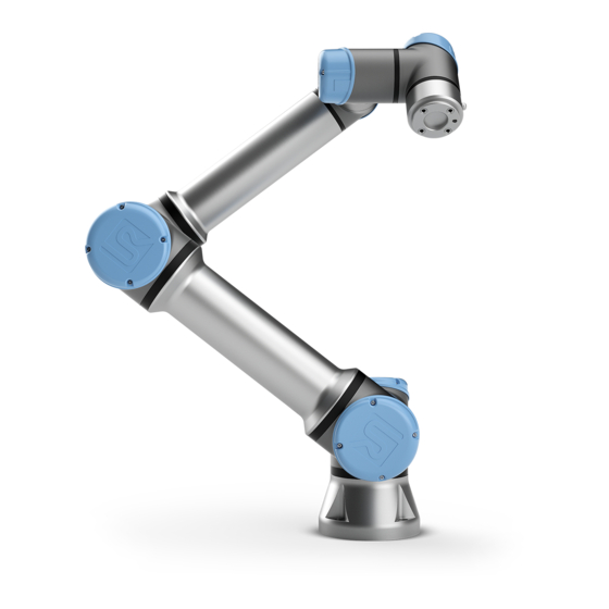
11 Quick Start 11.1 Robot Arm Basics The Universal Robot arm is composed of tubes and joints. You use the PolyScope to coordinate the motion of these joints, moving the robot and positioning its tool as desired - except for the area directly above and directly below the base. -
Page 92: Turning Control Box On/Off
11.2 Quick System Start-up 2. Mount the Robot arm on a sturdy and vibration-free surface. 3. Place the Control box on its Foot. 4. Connect the cable to the robot and the control box. 5. Plug in the main control box plug. DANGER: Tipping hazard. - Page 93 10. On the Initialize Robot screen, touch the Start button, for the robot to release its brake system. Note: Robot vibrates and makes clicking sounds indicating it is ready to be programmed NOTE: You can learn to program your robot on Universal Robots Academy at www.universal-robots.com/academy/ Version 5.0.2 II-9...
- Page 94 11.2 Quick System Start-up II-10 Version 5.0.2...
-
Page 95: Operational Mode Selection
** It is possible via the Installation to specify that the Speed Slider is enabled/visible in the run screen NOTE: • A Universal Robots robot is not equipped with a 3-Position En- abling Device. If the risk assessment requires the device, it must be attached before the robot is used. -
Page 96: Position Enabling Device
12.2 3-Position Enabling Device The three methods for configuring Operational Mode selection are described in the following subsections. Each method is exclusive, meaning that using one method, makes the other two methods inactive. Using Operational Mode Safety Input 1. In the Installation Tab, select Safety I/O. 2. -
Page 97: Manual High Speed
12.2 3-Position Enabling Device NOTE: The 3-Position Device, its behavior, its performance characteristics and operation must thoroughly comply with ISO 10218-1: article 5.8.3 for an enabling device. 12.2.1 Manual High Speed When the input is low, the robot is in Safeguard Stop. The Speed Slider is set to an initial value that corresponds to 250 mm/s and can be incrementally increased for higher speed. - Page 98 12.2 3-Position Enabling Device II-14 Version 5.0.2...
-
Page 99: Safety Configuration
13 Safety Configuration 13.1 Safety Settings Basics This section covers how to access the robot safety settings. It is made up of items that help you set up the robot Safety Configuration. DANGER: Before you configure your robot safety settings, your integrator must conduct a risk assessment to guarantee the safety of per- sonnel and equipment around the robot. -
Page 100: Setting A Safety Password
13.1 Safety Settings Basics You can find more safety system information in the Hardware Installation Manual. 13.1.2 Setting a Safety Password You must set a password to Unlock all safety settings that make up your Safety Configuration. Note: If no safety password is applied, you are prompted to set it up. 1. -
Page 101: Applying New Safety Configuration
13.2 Safety Menu Settings “Before working near the robot, make sure that the safety configuration is as expected. This can be verified e.g. by inspecting the safety checksum in the top right corner of PolyScope for any changes.” 13.1.4 Applying New Safety Configuration The robot is powered off while you make changes to the configuration. - Page 102 13.2 Safety Menu Settings 1. Factory Presets is where you can use the slider to select a predefined safety setting . The values in the table are updated to reflect the preset values ranging from Most Restricted to Least Restricted Note: Slider values are only suggestions and do not substitute a proper risk assessment.
-
Page 103: Safety Modes
13.2 Safety Menu Settings NOTE: You can switch back to Factory Presets for all robot limits to reset to their default settings. 13.2.2 Safety Modes Under normal conditions, i.e. when no protective stop is in effect, the safety system operates in a Safety Mode associated with a set of safety limits: Normal mode is the safety mode that is active by default Reduced mode is active when the robot Tool Center Point (TCP) is positioned beyond a Trigger... -
Page 104: Tolerances
13.2 Safety Menu Settings 13.2.3 Tolerances In the Safety Configuration the safety system limits are specified. The Safety System receives the values from the input fields and detects any violation if any these values are exceeded. The robot controller attempts to prevent any violations by making a protective stop or by reducing the speed. -
Page 105: Planes
13.2 Safety Menu Settings 13.2.5 Planes NOTE: Configuring planes is entirely based on features. We recommend you create and name all features before editing the safety config- uration, as the robot is powered off once the Safety Tab has been unlocked and moving the robot will be impossible. - Page 106 13.2 Safety Menu Settings 4. On the bottom right of the screen, in the Properties field, set up Name, Copy Feature and Restrictions. Note: In Copy Feature, only Undefined and Base are available. You can reset a configured safety plane by selecting Undefined If the copied feature is modified in the Features screen, a warning icon appears to the right of the Copy Feature text.
-
Page 107: Tool Position
13.2 Safety Menu Settings Yellow & Black Normal Plane (B) Blue & Green Trigger Plane (C) Black Arrow The side of the plane the tool and/or elbow is allowed to be on (For Normal Planes) Green Arrow The side of the plane the tool and/or elbow is allowed to be on (For Trigger Planes) Gray Arrow The side of the plane the tool and/or elbow is allowed to be on (For Disabled Planes) Freedriving Robot If the robot comes close to certain limits, while in Freedrive (see 18.6), you can experience a... -
Page 108: Tool Direction
13.2 Safety Menu Settings Position to change the position of the tool with respect to the tool flange of the robot. The position is considered for the safety functions for tool speed, tool force, stopping distance and safety planes. You can use an existing Tool Center Point as a base for defining new tool positions. A copy of the existing TCP, predefined in General menu, in TCP screen, can be accessed in Tool Position menu, in Copy TCP drop-down list. - Page 109 13.2 Safety Menu Settings NOTE: Configuration of the tool direction is based on features. We recom- mend you create desired feature(s) before editing the safety con- figuration, as once the Safety Tab has been unlocked, the robot arm powers off making it impossible to define new features. Limit Properties The Tool Direction limit has three configurable properties: 1.
- Page 110 13.2 Safety Menu Settings Alternatively, the Z axis of an existing TCP can be copied by selecting that TCP from the drop- down menu. 13.2.8 I/O The I/O are divided between inputs and outputs and are paired up so that each function provides a Category 3 and PLd I/O.
-
Page 111: Hardware
13.2 Safety Menu Settings WARNING: By default, the Safeguard Reset input function is configured for in- put pins 0 and 1. Disabling it altogether implies that the robot arm ceases to be Safeguard Stopped as soon as the Safeguard Stop input becomes high. - Page 112 13.2 Safety Menu Settings 1. In the Header tap Installation. 2. In the action menu on left tap Safety and select Hardware. 3. Input Safety password and Unlock the screen. 4. Deselect Teach Pendant to use robot without PolyScope interface. 5.
-
Page 113: Program
14 Run Tab The Run tab allows you to simply operate the robot arm and control box, using as few buttons and options as possible. You can combine simple operation with password protecting the pro- gramming part of PolyScope (see 22.3.2), to make the robot into a tool that can run exclusively pre-written programs. -
Page 114: Robot Age
14.4 Move Robot into Position The following variable types are available: bool A boolean variable whose value is either True or False. A whole number in the range from 2147483648 to 2147483647 (32 bit). float A floating point number (decimal) (32 bit). string A sequence of characters. - Page 115 14.4 Move Robot into Position Animation The animation shows the movement the robot arm is about to perform when you hold down the Auto tab. CAUTION: 1. Compare the animation with the position of the real robot arm and make sure that the robot arm can safely perform the movement without hitting any obstacles.
- Page 116 14.4 Move Robot into Position II-32 Version 5.0.2...
-
Page 117: Initialize Tab
15 Initialize Tab 15.1 Robot Arm State Indicator Located in the Header, the Initialize icon includes a status LED indicating Robot arm running state. • Red indicates theRobot arm is in a stopped state due to different possible reasons. • Yellow indicates the Robot arm is powered on, but it is not ready for normal operation. •... -
Page 118: Initializing The Robot Arm
15.4 Installation File 15.3 Initializing the Robot Arm DANGER: Always verify the actual payload and installation are correct before starting up the Robot arm. If these settings are incorrect, the Robot arm and Control Box will not function correctly and may become dangerous to people or equipment. - Page 119 15.4 Installation File These settings can be set using the various screens under the Installation tab, except for the I/O domains which are set in the I/O tab (see 19). It is possible to have more than one installation file for the robot. Created programs created use the active installation and load this installation automatically when used.
- Page 120 15.4 Installation File II-36 Version 5.0.2...
-
Page 121: Program Tab
16 Program Tab The program tab shows the current program being edited. 16.1 Program Tree The Program Tree displays the program as a list of commands called Program Nodes. The pro- gram name is displayed directly above this list of commands. To the right of the Program Tree, information relating to the selected command is displayed. -
Page 122: Program Execution Indication
16.1 Program Tree 16.1.1 Program Execution Indication The Program Tree contains visual cues informing about the command currently being executed by the robot controller. A small indicator icon is displayed to the left of the command icon, and the name of the executing command and any commands of which this command is a sub- command (typically identified by the command icons) are highlighted with blue. -
Page 123: Empty Node
16.2 Command Tab Move Up & Down buttons change the position of a node. button cuts a node and allows it to be used for other actions (e.g., paste it on other place on the Program Tree). Copy button allows copies a node and allows it to be used for other actions (e.g., paste it on other place on the Program Tree). - Page 124 16.2 Command Tab In the Command Tab field, there are additional check-box options descibred in the following subsections. Add Before Start Sequence Select this check-box to add a set of commands before running your program. Set Initial Variables Values Select this check-box to set variable values before the program (and any threads) start to run. The Command Tab field is replaced by an Initial Variable Value field and Init Variables appears at the top of your program tree.
-
Page 125: Graphics Tab
16.3 Graphics Tab 16.3 Graphics Tab Graphical representation of the current robot program. The path of the TCP is shown in 3D view, with motion segments in black, and blend segments (transitions between motion segments) shown in green. The green dots specify the positions of the TCP at each of the waypoints in the program. -
Page 126: Variables Tab
16.5 Basic program nodes 16.4 Variables Tab The Variables tab shows the live values of variables in the running program, and keeps a list of variables and values between program runs. It only appears when it has information to display. The variables are ordered alphabetically by their names. - Page 127 16.5 Basic program nodes Movement Types You can select one of three types of movements: MoveJ, MoveL and MoveP. Each movement type is explained below. • moveJ makes movements that are calculated in the robot arm joint space. Each joint is controlled to reach the desired end location at the same time.
- Page 128 16.5 Basic program nodes Shared parameters The shared parameters in the bottom right corner of the Move screen apply to the movement from the previous position of the robot arm to the first waypoint under the command, and from there to each of the following waypoints. The Move command settings do not apply to the path going from the last waypoint under that Move command.
- Page 129 16.5 Basic program nodes Cruise Deceleration Acceleration Time Figure 16.1: Speed profile for a motion. The curve is divided into three segments: acceleration, cruise and deceleration. The level of the cruise phase is given by the speed setting of the motion, while the steepness of the acceleration and deceleration phases is given by the acceleration parameter.
- Page 130 16.5 Basic program nodes Example Consider a pick and place application as an example (see figure 16.2), where the robot is currently at Waypoint 1 (WP_1), and it needs to pick up an object at Waypoint 3 (WP_3). To avoid collisions with the object and other obstacles (O), the robot must approach WP_3 in the direction coming from Waypoint 2 (WP_2).
- Page 131 16.5 Basic program nodes WP_1 WP_2 WP_3 Figure 16.3: Blend over WP_2 with radius r, initial blend position at p1 and final blend position at p2. O is an obstacle. WP_1 WP_2 WP_3 WP_4 Figure 16.4: Blend radius overlap not allowed (*). Conditional blend trajectories The blend trajectory is affected both by the waypoint where the blend radius is set and the following one in the program tree.
- Page 132 16.5 Basic program nodes WP_I MoveL WP_1 WP_I WP_1 (blend) WP_2 (blend) if (digital_input[1]) then WP_F_1 WP_2 else WP_F_2 WP_F_1 WP_F_2 Figure 16.5: WP_I is the initial waypoint and there are two potential final waypoints WP_F_1 and WP_F_2, depending on a conditional expression. The conditional if expression is evaluated when the robot arm enters the second blend (*).
- Page 133 16.5 Basic program nodes trajectory types (bullet 2) can be seen in figure 16.7. WP_2 WP_1 WP_3 Figure 16.7: Blending from a movement in joint space (MoveJ) to linear tool movement (MoveL). Pure joint space blends (bullet 1), however, may behave in a way that is less intuitive, since the robot will try to achieve the smoothest possible trajectory in Joint space taking velocities and time requirements into account.
- Page 134 16.5 Basic program nodes Relative Waypoint A waypoint with the position given relative to the robot arm’s previous position, such as “two centimeters to the left”. The relative position is defined as the difference between the two given positions (left to right). Note: repeated relative positions can move the robot arm out of its workspace.
-
Page 135: Wait
16.5 Basic program nodes var=p[0.5,0.0,0.0,3.14,0.0,0.0]. The first three are x,y,z and the last three are the orienta- tion given as a rotation vector given by the vector rx,ry,rz. The length of the axis is the angle to be rotated in radians, and the vector itself gives the axis about which to rotate. The position is always given in relation to a reference frame or coordinate system, defined by the selected feature. -
Page 136: Popup
16.5 Basic program nodes 16.5.3 Set Sets either digital or analog outputs to a given value. The command can also be used to set the payload of the robot arm. Adjusting the payload weight can be necessary to prevent the robot from triggering a protective stop, when the weight at the tool differs from the expected payload. -
Page 137: Halt
16.5 Basic program nodes The popup is a message that appears on the screen when the program reaches this command. The style of the message can be selected, and the text itself can be given using the on-screen keyboard. The robot waits for the user/operator to press the “OK” button under the popup before continuing the program. -
Page 138: Folder
16.6 Advanced program nodes 16.5.7 Folder A Folder is used to organize and label specific parts of a program, to clean up the program tree, and to make the program easier to read and navigate. Folders have no impact on the program and its execution. 16.6 Advanced program nodes 16.6.1 Loop Loops the underlying program commands. -
Page 139: Subprogram
16.6 Advanced program nodes When looping using an expression as end condition, PolyScope provides an option for continu- ously evaluating that expression, so that the “loop” can be interrupted anytime during its execu- tion, rather than just after each iteration. 16.6.2 SubProgram A Sub Program can hold program parts that are needed several places. -
Page 140: Assignment
16.6 Advanced program nodes 16.6.3 Assignment Assigns values to variables. An assignment puts the computed value of the right hand side into the variable on the left hand side. This can be useful in complex programs. 16.6.4 If An If...Else command construction changes the robot’s behavior based on sensor inputs or vari- able values. -
Page 141: Script
16.6 Advanced program nodes Note: You can select the Check expression continuously checkbox to allow the conditions of the If command and ElseIf statements to be evaluated while the contained lines are executed. If an expression within the If command is evaluated as False, the ElseIf or Else statements are followed. -
Page 142: Event
16.6 Advanced program nodes 16.6.6 Event An event can be used to monitor an input signal, and perform some action or set a variable when that input signal goes high. For example, in the event that an output signal goes high, the event program can wait for 200ms and then set it back to low again. -
Page 143: Switch
16.7 Wizards 16.6.8 Switch A Switch Case construction can make the robot change behavior based on sensor inputs or variable values. Use the Expression Editor to describe the base condition and define the cases under which the robot should proceed to the sub-commands of this Switch. If the condition is evaluated to match one of the cases, the lines inside the Case are executed. - Page 144 16.7 Wizards A pallet operation can perform a sequence of motions in a set of places given as a pattern (see 16.7.1.1). At each of the positions in the pattern, the sequence of motions will be run relative to the pattern position. Programming a Pallet Operation The steps to go through are as follows;...
-
Page 145: Seek
16.7 Wizards points, where the points define the edges of the pattern. For Line this is the two end points, for Square this is three of the four corner points, where as for Box this is four of the eight corner points. - Page 146 16.7 Wizards Stacking Destacking When programming a seek operation for working on a stack, one must define s the starting point, d the stack direction and i the thickness of the items in the stack. On top of this, one must define the condition for when the next stack position is reached, and a special program sequence that will be performed at each of the stack positions.
- Page 147 16.7 Wizards Destacking When destacking, the robot arm moves from the starting position in the given direction to search for the next item. The condition on the screen determines when the next item is reached. When the condition becomes satisfied, the robot remembers the position and performs the special sequence.
-
Page 148: Force
16.7 Wizards Note: A direction does not consider the orientations of the points. Next Stacking Position Expression The robot arm moves along the direction vector while continuously evaluating whether the next stack position has been reached. When the expression is evaluated to True the special sequence is executed. - Page 149 16.7 Wizards Feature selection The Feature menu is used to select the coordinate system (axes) the robot will use while it is operating in force mode. The features in the menu are those which have been defined in the installation (see 17.3). Force mode type The are four different types of force mode each determining the way in which the selected feature will be interpreted.
-
Page 150: Urcaps
16.8 URCaps Force value selection • Force or torque value can be set for compliant axes, and robot arm adjusts its position to achieve the selected force. • For non-compliant axes robot arm will follow the trajectory set by the program. For translational parameters, the force is specified in Newtons [N] and for rotational the torque is specified in Newton meters [Nm]. -
Page 151: The First Program
16.9 The First Program 16.9 The First Program A program is a list of commands telling the robot what to do. PolyScope allows people with only little programming experience to program the robot. For most tasks, programming is done entirely using the touch panel without typing in any cryptic commands. Tool motion is the part of a robot program that teaches the Robot Arm how to move. - Page 152 16.9 The First Program WARNING: 1. Do not drive the robot into itself or anything else as this may cause damage to the robot. 2. Keep your head and torso outside the reach (workspace) of the robot. Do not place fingers where they can be caught. 3.
-
Page 153: Installation Tab
17 Installation Tab 17.1 General The Installation Tab allows you to configure the settings which affect the overall performance of the robot and PolyScope. 17.1.1 TCP Configuration A Tool Center Point (TCP) is a point on the robot’s tool. The TCP is defined and named in the Installation Tab Setup for the Tool Center Point screen (shown above). - Page 154 17.1 General tap Set as default. A TCP offset is designated as active to determine all linear motions in Cartesian coordinate system space. The motion of the active TCP is visualized on the Graphics Tab (see 16.3). Before a program runs, the default TCP is set as the active TCP. Within a program, any of the specified TCPs can be set as active for a particular movement of the robot (see 16.5.1 and 16.5.3).
- Page 155 17.1 General Teaching TCP orientation 1. Tap Orientation. 2. Select a feature from the drop-down list. (See 17.3) for additional information on defining new features 3. Tap Select point and use Move tool arrows to a position where the tool’s orientation and the corresponding TCP coincide with the selected features’s coordinate system.
-
Page 156: Mounting
17.1 General NOTE: Follow the these guidelines for best Payload Estimation results: • Ensure the four TCP positions are as different as possible from each other • Perform the measurements within a short timespan WARNING: • Avoid pulling on the tool and/or attached payload before and during estimation •... -
Page 157: I/O Setup
17.1 General 2. Telling the controller about the direction of gravity. An advanced dynamics model gives the Robot arm smooth and precise motions, as well as allows the Robot arm to hold itself in Freedrive Mode. For this reason, it is important to mount the Robot arm correctly. -
Page 158: I/O Signal Type
17.1 General Note: When the Tool Communication Interface TCI is enabled (see 17.1.10), the tool analog input becomes unavailable. The Input and Output sections list types of I/O signals such as: • Digital standard general purpose, configurable and tool • Analog standard general purpose and tool •... -
Page 159: Conveyor Tracking
17.1 General when a program is running and high when it is stopped or paused. These values can be set while the program is running. General purpose output registers of type boolean and digital MODBUS output signals also support this. Finally, it is also possible to specify whether an output can be controlled on the I/O tab (by either programmers, or both operators and programmers) or if it is only robot programs that may alter the output value. -
Page 160: Variables
17.1 General 17.1.8 Variables Variables created on the Variables screen are called Installation Variables and are used like nor- mal program variables. Installation Variables are distinct because they keep their value even if a program stops and then starts again, and when the Robot arm and/or Control Box is powered down and powered up again. -
Page 161: Startup
17.1 General 17.1.9 Startup The Startup screen contains settings for automatically loading and starting a default program, and for auto-initializing the Robot arm during power up. WARNING: 1. When autoload, auto start and auto initialize are enabled, the robot runs the program as soon as the Control Box is pow- ered up as long as the input signal matches the selected signal level. -
Page 162: Tool
17.2 Safety screen or tapping the Stop button in the Dashboard disables the auto start feature until the Run button is pressed again. Auto Initialization The Robot arm is automatically initialized. On the specified external input signal edge transition, the Robot arm is completely initialized, regardless of the visible screen. Brake Release is the final initialization stage. -
Page 163: Features
17.3 Features 17.3 Features The Feature, is a representation of an object that is defined with a name for future reference and a six dimensional pose (position and orientation) relative to the robot base. Some subparts of a robot program consist of movements executed relative to specific objects other than the base of the Robot arm. -
Page 164: Using A Feature
17.3 Features applicable to the specific object. To accurately define the direction of a linear conveyor, define two points of a Line feature with as much physical separation as possible. The Point feature can also be used to define a linear conveyor, however, the user must point the TCP in the direction of the conveyor movement. -
Page 165: Addine A Line
17.3 Features 17.3.3 Addine a Line Push the Line button to add a line feature to the installation. The line feature defines lines that the robot needs to follow. (e.g., when using conveyor tracking). A line l is defined as an axis between two point features p1 and p2 as shown in figure 17.3. -
Page 166: Plane Feature
17.3 Features 17.3.4 Plane Feature Select the plane feature when you need a frame with high precision: e.g., when working with a vision system or doing movements relative to a table. Adding a plane 1. In Installation, select Features. 2. Under Features select Plane. Teaching a plane When you press the plane button to create a new plane, the on-screen guide assists you creating a plane. -
Page 167: Example: Manually Updating A Feature To Adjust A Program
17.3 Features NOTE: You can re-teach the plane in the opposite direction of the x-axis, if you want that plane to be normal in the opposite direction. Modify an existing plane by selecting Plane and pressing Modify Plane. You will then use the same guide as for teaching a new plane. -
Page 168: Example: Dynamically Updating A Feature Pose
17.4 Fieldbus table position as a feature P1 in the installation, the program with a MoveL command configured relative to the plane can be easily applied on additional robots by just updating the installation with the actual position of the table. The concept applies to a number of Features in an application to achieve a flexible program can solve the same task on many robots even though if other places in the work space varies between installations. -
Page 169: Modbus Client I/O Setup
17.4 Fieldbus Robot Program MoveJ if (digital_input[0]) then P1_var = P1 else P1_var = P2 MoveL # Feature: P1_var Figure 17.7: Switching from one plane feature to another 17.4.1 MODBUS client I/O Setup Here, the MODBUS client (master) signals can be set up. Connections to MODBUS servers (or slaves) on specified IP addresses can be created with input/output signals (registers or digital). - Page 170 17.4 Fieldbus Delete unit Push this button to delete the MODBUS unit and all signals on that unit. Set unit IP Here the IP address of the MODBUS unit is shown. Press the button to change it. Sequential mode Available only when Show Advanced Options (see 17.4.1) is selected. Selecting this checkbox forces the modbus client to wait for a response before sending the next request.
- Page 171 17.4 Fieldbus Set signal name Using the on-screen keyboard, the user can give the signal a name. This name is used when the signal is used in programs. Signal value Here, the current value of the signal is shown. For register signals, the value is expressed as an unsigned integer.
-
Page 172: Ethernet/Ip
17.4 Fieldbus Response time [ms ] Time between modbus request sent, and response received - this is up- dated only when communication is active. Modbus packet errors Number of received packets that contained errors (i.e. invalid lenght, missing data, TCP socket error). Timeouts Number of modbus requests that didn’t get response. -
Page 173: Move Tab
18 Move Tab On this screen, you can move (jog) the robot arm directly, either by translating/rotating the robot tool, or by moving robot joints individually. 18.1 Move Tool Hold down any of the Move Tool arrows to move the robot arm in a particular direction. •... -
Page 174: Tool Position
18.3 Tool Position When the robot TCP is no longer in proximity of the limit, the 3D representation disappears. If the TCP is in violation or very close to violating a boundary limit, the visualization of the limit turns red. Feature In the top left corner of the Robot field, under Feature, you can define how to control the robot arm relative to View, Base or Tool features. - Page 175 18.3 Tool Position “shadow” of the robot arm shows the target position of the robot arm controlled by the specified values on the right hand side of the screen. Push the magnifying glass icons to zoom in/out or drag a finger across to change the view. If the specified target position of the robot TCP is close to a safety or trigger plane, or the orien- tation of robot tool is near the tool orientation boundary limit (see 13.2.5), a 3D representation of the proximate boundary limit is shown.
-
Page 176: Joint Position
18.6 Freedrive subtract an amount to/from the current value. Pressing and holding down a button will directly increase/decrease the value. The longer the button is down, the larger the increase/decrease will be. 18.3.1.4 OK button If this screen was activated from the Move tab (see 18), clicking the OK button will return to the Move tab, where the robot arm will move to the specified target. - Page 177 18.6 Freedrive WARNING: 1. In the Setup tab, if the gravity setting (see 17.1.2) is wrong, or the robot arm carries a heavy load, the robot arm can start moving (falling) when you press the Freedrive tab. In that case, release Freedriveagain. 2.
- Page 178 18.6 Freedrive II-94 Version 5.0.2...
-
Page 179: Robot
19 I/O Tab 19.1 Robot On this screen you can always monitor and set the live I/O signals from/to the robot control box. The screen displays the current state of the I/O, including during program execution. If anything is changed during program execution, the program will stop. At program stop, all output signals will retain their states. -
Page 180: Modbus
19.2 MODBUS 19.2 MODBUS Here, the digital MODBUS client I/O signals as set up in the installation are shown. If the signal connection is lost, the corresponding entry on this screen is disabled. 19.2.1 Inputs View the state of digital MODBUS client inputs. 19.2.2 Outputs View and toggle the state of digital MODBUS client outputs. -
Page 181: Log Tab,
20 Log Tab 20.1 Readings The top half of the screen displays the ”health” of the Robot Arm and Control Box. 20.2 Joint Load The left side of the screen shows information related to the Control Box, while the right side of the screen displays robot joint information. - Page 182 20.4 Saving Error Reports • Fault • Internal PolyScope exceptions • Protective Stop • Unhandled exception in URCap • Violation The exported report contains: a user program, a history log, an installation and a list of running services. Error Report A detailed status report is available when a paper clip icon appears on the log line.
-
Page 183: File Manager
21 File manager The File Manager refers to three icons that allow you to create, load and configure Programs and Installations: New..., Open... and Save..The File Path displays your current loaded Program name and the type of Installation. File Path changes when you create or load a new Program or Installation. - Page 184 21.2 New... 3. In the Safety Configuration box, select Apply and restart to prompt robot reboot. 4. Select Set Installation to set installation for the current Program. 5. In File Path, verify that the desired installation name is displayed. 21.2 New... Allows you to create a new Program and/or Installation.
-
Page 185: Save
21.3 Save... 21.3 Save... Save... proposes three options. Depending on the program/installation you load-create, you can: Save All to save the current Program and Installation immediately, without the system prompting to save to a different location or different name. Note: If no changes are made to the Program or Installation, the Save All... - Page 186 21.3 Save... II-102 Version 5.0.2...
-
Page 187: Hamburger Menu
22 Hamburger menu 22.1 Help You can find definitions for all elements that make up PolyScope capabilities. 1. In the right corner of the Header, tap the Hamburger menu and select Help. 2. Tap one of the red question marks that appears, to define desired element. 3. -
Page 188: Password
22.3 Settings 22.3.2 Password Mode The operational mode password prevents unauthorized modification of robot setup, by creating two different user roles on PolyScope: Automatic and Maual. When you set operational mode password, programs or installations can only be created and loaded in manual mode. Any time you enter manual mode, PolyScope prompts for the password that was previously set on this screen. - Page 189 22.3 Settings 4. If you wish to proceed with the installation of that URCap, press Restart. After that step, the URCap is installed and ready to be used. 5. To eliminate an installed URCap, select it from Active URCaps, press the - button and press Restart so changes can take effect.
- Page 190 22.3 Settings II-106 Version 5.0.2...
-
Page 191: Glossary
Glossary Stop Category 0 Robot motion is stopped by immediate removal of power to the robot. It is an uncontrolled stop, where the robot can deviate from the programmed path as each joint brake as fast as possible. This protective stop is used if a safety-related limit is exceeded or in case of a fault in the safety-related parts of the control system. - Page 192 22.3 Settings II-108 Version 5.0.2...
-
Page 193: Index
Index About ........II-103 Factory Presets ......II-18 AfterEnd . - Page 194 mode: Automatic ......II-4 Reduced ........II-21 mode: Manual .
- Page 195 Trigger Reduced Mode ....II-21 TCI ........II-51 Teach Pendant .
Need help?
Do you have a question about the UR5e and is the answer not in the manual?
Questions and answers