Panasonic DP-8032 Service Manual
Digital imaging systems
Hide thumbs
Also See for DP-8032:
- Operating instructions manual (104 pages) ,
- Operating instructions manual (240 pages)
Table of Contents
Advertisement
This service information is designed for experienced repair technicians only and is not intended for use by the general public.
It does not contain warnings or cautions to advise non-technical individuals of potential dangers in attempting to service a product.
Products powered by electricity should be serviced or repaired only by experienced professional technicians. Any attempt to service
or repair the product or products dealt within this service information by anyone else could result in serious injury or death.
Digital Imaging Systems
WARNING
© Panasonic Communications Co., Ltd. 2008.
Unauthorized copying and distribution is a violation of law.
Order Number: MGCS080801C0
DP-8032 / 8025
[ Version 1.2 ]
H21
Advertisement
Table of Contents
Troubleshooting

Subscribe to Our Youtube Channel
Related Manuals for Panasonic DP-8032


Summary of Contents for Panasonic DP-8032
- Page 1 Products powered by electricity should be serviced or repaired only by experienced professional technicians. Any attempt to service or repair the product or products dealt within this service information by anyone else could result in serious injury or death. © Panasonic Communications Co., Ltd. 2008. Unauthorized copying and distribution is a violation of law.
-
Page 4: Important Notice
(This interrupts all the power to the machine) 4. Unplug the AC Power Cord. * The specifications are subject to change without notice. Panasonic Communications Co., Ltd. reserves the right to make improvements in the product design without reservation and without notice. - Page 5 < Beispiel > Hinweis:...
-
Page 6: For Your Safety
Precautions For Your Safety To prevent severe injury and loss of life, read this section carefully before servicing the Panasonic machine to ensure proper, and safe operation of your machine. Please ensure that the machine is installed near a wall outlet, and is easily accessible. -
Page 7: Operating Safeguards
Once a month, unplug the machine and check the power cord for the following. If you notice any unusual condition, contact your authorized Panasonic dealer The power cord is plugged firmly into the receptacle. The plug is not excessively heated, rusted, or bent. - Page 8 CAUTION Operating Safeguards Do not place a magnet near the safety switch of the machine. A magnet can activate the machine accidentally, resulting in injuries. Do not use a highly flammable spray, or solvent near the machine. It can cause fire. When copying a thick document, do not use excessive force to press it against the scanning glass.
- Page 12 memo...
-
Page 13: Table Of Contents
Table of Contents Specifications Table ......15 System Description ......225 1.1. Copy Function.........15 6.1. Printing Process ........225 1.2. Fax, Printer and Internet Fax 6.2. Precaution with Consumables....226 Functions ..........24 6.3. New Image Stabilizing Technology ..227 1.3. System Combination.......32 6.4. - Page 14 Table of Contents 8.17. Installing the Automatic Document Feeder (DA-AS201) and the Inverting Automatic Document Feeder (DA-AR251) ......... 304 8.18. Installing the Platen Cover (DA-UC200) ......... 310 8.19. Installing the Key Counter Harness Kit (DA-KH200) ......... 311 8.20. Installing the Dehumidifier Heater Kit (DZTQ000048R) ........
-
Page 15: Specifications Table
DP-8032/8025 1 Specifications Table 1.1. Copy Function Description Items Remarks DP-8032 DP-8025 Basic Specifications 1 Type Desktop 2 Platen Fixed 3 Original Position Platen Left / Rear ADF / i-ADF Left / Center 4 Recording Paper Path Center 5 Face Up / Face Down... - Page 16 DP-8032/8025 Description Items Remarks DP-8032 DP-8025 Capacity 550 sheets x 2 Auto Size Setting Low Level Warning Empty Only USA and Canada LTR : 20 lb (75 g/m Bypass Other Destinations Capacity 50 sheets A4 : 80 g/m Auto Size Setting...
- Page 17 DP-8032/8025 Description Items Remarks DP-8032 DP-8025 Stand for 3-Paper Tray Option Low Plain Stand Configuration Stand for 2-Paper Tray Option High Plain Stand Configuration For EU and Other 3 Platen Cover Option Destinations Free Stop From 30 to 70 degrees.
- Page 18 DP-8032/8025 Description Items Remarks DP-8032 DP-8025 Max. 3 way using Optional Multi Tray Function Exit Tray (Inner) and Exit Tray (Outer) or Finisher. Shift Tray Function No Manual Stapling. Not available with Rotation. Staple Function Not available with INV, INV-R, A5, A5-R or B5-R.
- Page 19 DP-8032/8025 Description Items Remarks DP-8032 DP-8025 Auto Paper Tray Selection Reservation while Power On Auto Start Initial Energy Saver Automatically enters the Sleep or Shutdown Mode after Standby Mode Yes (140Wh) 15 minutes from the Standby or Energy Saver Mode.
- Page 20 DP-8032/8025 Description Items Remarks DP-8032 DP-8025 4 in 1 6 in 1 For USA and Canada For EU and Other 8 in 1 Destinations Copy from four 1-Sided Booklet Mode pages to 1 Booklet Mode sheet. Duplex Copy 1→2 2→1 Available only when using the i-ADF.
- Page 21 DP-8032/8025 Description Items Remarks DP-8032 DP-8025 3 Control Panel Display Wide Touch Panel LCD GREEN : Scanning / Printing Status Lamp : Alarm / Warning Original Size Copy Size Keypad Clear Stop Start Energy Saver Multi Size Feed Sort / Finish...
- Page 22 DP-8032/8025 Description Items Remarks DP-8032 DP-8025 Add Paper (Under 50 sheets) Paper Jam Indication Paper Jam Location Service Alert Call User Error Machine Error History of Jam Errors 4 Main Unit Total Counter Yes (Standard) Mechanical Counter Max. Weight of Documents 11.02 lb (5 kg)
- Page 23 DP-8032/8025 Description Items Remarks DP-8032 DP-8025 Packing Configuration 28.58 x 32.91 x 42.91 in 1 Packing Dimension (726 x 836 x 1090 mm) 2 Packing Weight 218.26 lb (99 kg) 3 Accessories Process Unit Developer Toner Toner Waste Container Outer Tray...
-
Page 24: Fax, Printer And Internet Fax Functions
DP-8032/8025 1.2. Fax, Printer and Internet Fax Functions 1.2.1. Fax Function Description Items Remarks DP-8032 DP-8025 Main Specifications 1 Compatibility ITU-T Std & Non-Std 2 PSTN Line Port 1-Line Only 3 Leased Line Port 4 V.24 Line Port 5 Modem Speed 33.6 - 2.4kbps... - Page 25 DP-8032/8025 Description Items Remarks DP-8032 DP-8025 5 Effective Scanning Width (10.7 in) / A3 (292 mm) 6 A3 Size TX/RX Conforms to ITU-T A3 7 Reduction XMT A3 to B4 / A3 to A4 / B4 to A4 8 ADF Capacity...
- Page 26 DP-8032/8025 Description Items Remarks DP-8032 DP-8025 8 Direct Dialing Voice mode (Monitor Dialing) Up to 15 times at 0 to 15 min. 9 Automatic Redialing intervals Pressing the REDIAL/PAUSE 10 Manual Redialing button 11 Line Monitor Speaker 12 Chain Dialing (Hybrid Dial)
- Page 27 DP-8032/8025 Description Items Remarks DP-8032 DP-8025 7 90 Degree Rotation Reception 8 Duplex Printing Polling 1 Polling 2 Turnaround Polling 3 Multi-Station Polling Max. 270 stations 4 Deferred Polling Max. 50 timers 5 Deferred Multi-Station Max. 50 timers / 270 stations...
- Page 28 DP-8032/8025 Description Items Remarks DP-8032 DP-8025 5 Confidential XMT / Polling 6 Confidential Center 7 Mailbox XMT / Polling 8 Mailbox Center 9 File XMT Received File Transfer 10 Fax Forward (Only with Internet FAX Option) 11 Sub-Address XMT T. Routing...
- Page 29 DP-8032/8025 Description Items Remarks DP-8032 DP-8025 Requires Optional PCL6 9 PDL (PCL6) Emulation Kit. Requires Optional PS / PCL6 10 PDL (PS3) Emulation Kit Custom Size/Post Card Size 11 Duplex Printing is not available. 12 Collation Stack 13 Network Printing...
- Page 30 DP-8032/8025 Description Items Remarks DP-8032 DP-8025 TIFF can also be converted to 8 File Format Mult-page TIFF / PDF PDF with the PDMS Software Auto Pop-up on the PC Screen 9 Completion Notice (requires Network Status Monitor - installed with PDMS...
- Page 31 Confirmation 6 DHCP Client Lightweight Directory Access 7 LDAP Protocol Selectable, PDMS / TIFF 8 TIFF Viewer Viewer Certainty Email from RCV side to 1 Comm. Journal (w / Image) Panasonic Internet FAX's only 1 Email Address Ver. 1.2 2008...
-
Page 32: System Combination
2nd Paper Tray (CST2 PC Board) 3rd Paper Tray (CST3 PC Board) 4th Paper Tray (CST2 PC Board) Standard Configuration Option Note: Depict a DP-8032 with the USA/Canada standard configuration. The configuration may differ depending on the destinations. Ver.1.2 2008... -
Page 33: Options List
DP-8032/8025 1.4. Options List 1. Options Option Name Option Number Remarks Printer Controller Module for PCL6 DA-PC302 Multi Page Description Language DA-MC302 Controller Module for PS/PCL6 Document Distribution System DA-WR10 Fax Communication Board DA-FG300 G3 Fax Communication Additional Optional Sorting Image... -
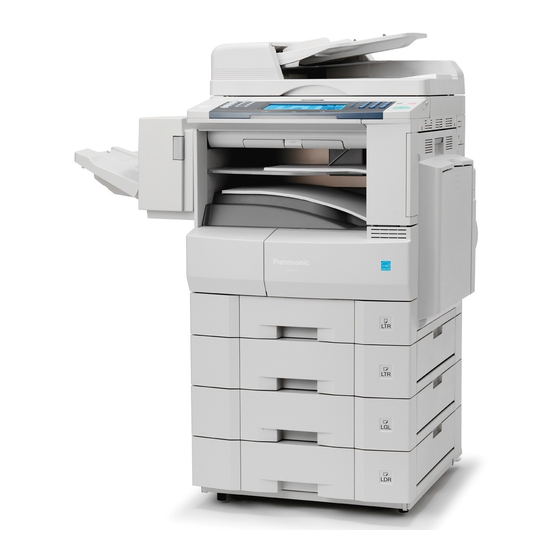
Page 34: External View
DP-8032/8025 1.5. External View 1. Standard Configuration (For USA Only) Product complies with DHHS Rules 21 CFR Subchapter J in effect at date of manufacture. Top View Manufacturer's Name and Address Factory ID 27.83 in (707 mm) 23.58 in (599 mm) - Page 35 DP-8032/8025 3. Space Requirements With Options Main Unit 3.94 in (100 mm) 14.2 in (379 mm) 23.58 in (599 mm) 3.94 in (100 mm) 51.65 in (1312 mm) 15.94 in (405 mm) 3.94 in (100 mm) 46.38 in (1178 mm) Main Unit + Outer Exit Tray 3.94 in (100 mm)
- Page 36 A0001 ~ Y9999 = 100,000 ~ 329,976 units (Letters “I” and “O” are skipped) Model Number and Destination Code (Main Unit) 3-Digit number or alphanumeric representation (Except Letters “I” and “O”) For Example: = DP-8032-PU = DP-8032-PB = DP-8025-PU DP-8025-PB Production Facility Production Year...
-
Page 37: Control Panel
DP-8032/8025 1.6. Control Panel DP-8032 1.7. Fans and Motors Transport Motor (1320) ADF Motor (1801) Scanning Motor (201) Main Motor (907) Fan (459) LVPS Fan (322) Toner Motor (958) LSU Fan (315) Lift DC Motor (1152) Ver. 1.2 2008... -
Page 38: Clutches And Switches
DP-8032/8025 1.8. Clutches and Switches ADF Roller Clutch (1788) Intermediate Clutch (969) Feed 2 Roller Clutch (1787) Micro Switch (461) Registration Roller Clutch (957) Sheet Bypass Feed Roller Clutch (957) Paper Feed Roller Clutch (1105) Intermediate Roller Clutch (957) ILS PCB (19124) -
Page 39: Disassembly Instructions
DP-8032/8025 2 Disassembly Instructions 2.1. General Disassembly Pertinent Disassembly Instruction sections are shown below. Ver. 1.2 2008... -
Page 40: Disassembly Instructions
DP-8032/8025 2.2. Disassembly Instructions 2.2.1. Inverting-Automatic Document Feeder (i-ADF) Unit (1) Open the ADF Cover (1831). (2) Remove 4 Silver Screws (B1). (3) Lift the ADF Input Tray (1604). (4) Slightly pull the right edge of the ADF Rear Cover upward. - Page 41 DP-8032/8025 (15) Remove the Snap Ring (S9). (16) Remove the Pin (744). (17) Remove the ADF Shaft (1724). (18) Remove the ADF Roller (1728). (19) Remove the Snap Ring (S9). (20) Remove the Pre-Feed Roller Shaft (1730). (21) Remove the Pre-Feed Roller (1731).
- Page 42 DP-8032/8025 (30) Disconnect all Connectors on the ADF PC Board. (31) Remove 2 Screws (19). (32) Remove the ADF PC Board (1907). (33) Remove 2 Screws (24). (34) Remove the ADF Motor (1801). (35) Remove 6 Screws (19). (36) Remove the Sensor Bracket (1663).
- Page 43 DP-8032/8025 < Cleaning ADF Roller, Pre-Feed Roller, Drive Roller and Feed 2 Roller> (1) Open the ADF Cover (1831). (2) Clean the ADF Roller (1728), Pre-Feed Roller (1731), Drive Roller (1872) and the Feed 2 Roller (1753) with a soft cloth, saturated with isopropyl alcohol.
- Page 44 DP-8032/8025 CAUTION Denotes hazards that could result in minor injury or damage to the machine. THIS PRODUCT CONTAINS A LITHIUM BATTERY. REPLACE ONLY WITH THE SAME OR EQUIVALENT TYPE. IMPROPER USE OR REPLACEMENT MAY CAUSE OVERHEATING, RUPTURE OR EXPLOSION RESULTING IN INJURY OR FIRE.
- Page 45 DP-8032/8025 (10) Disconnect 4 Harnesses on the PNL1 PC Board (CN223, CN225, CN229 and CN230). (11) Remove 4 Screws (F10). (12) Remove the PNL1 PC Board (1908). (13) Remove 7 Screws (F10). (14) Disconnect the Harness on the PNL2 PC Board (CN251).
- Page 46 DP-8032/8025 (19) Remove 2 Screws (P5). (20) Release 2 Latch Hooks and remove the Upper Control Panel Cover (122). (21) Remove 1 Screw (P5). (22) Remove the PNL4 PC Board (114). (23) Remove 4 Screws (P5). (24) Remove the PNL3 PC Board (113).
-
Page 47: Scanner Unit
DP-8032/8025 (28) Remove the Touch Panel (127). 2.2.3. Scanner Unit (1) Remove the Left and Right Platen Covers (514, 516) and the Control Panel Assembly. (Refer to 2.2.2.) (2) Remove 2 Screws (19). (3) Remove the Glass Assembly (557). (4) Remove the Glass S (559). - Page 48 DP-8032/8025 (6) Remove 4 Screws (19). (7) Remove the F/R Scanner Frame (240). (8) Remove 2 Screws (19). (9) Remove the 2 Lamp Plate Springs (232). (10) Disconnect the Harness on the LFB PC Board (CN181). (11) Remove the Scanning Lamp (204).
- Page 49 DP-8032/8025 (17) Remove 2 Screws (19). (18) Remove the Inverter PC Board (268). (19) Remove 2 Red Screws (D24). (20) Remove the FPC Cable Holder A (215) Assembly. (21) Holding by the center, slowly move the Lamp Base Assembly towards the left of the Scanner Base Frame.
- Page 50 DP-8032/8025 <Removing the Scanner Motor> (27) Remove 4 Silver Screws (S6). (28) Open the Rear Cover. (29) Remove 4 Silver Screws (S6). (30) Remove the Rear Right Cover (507) and the Right Rear Cover (518). (31) Remove the E-Ring (5Y).
- Page 51 DP-8032/8025 (39) Remove 2 Screws (36). (40) Remove the Scanning Motor (201). (41) Disconnect the Harness on the SC PC Board (CN106). (42) Release 2 Latch Clips and remove the Ferrite Core. (43) Remove 3 Red Screws (D24). (44) Remove the CCD Assembly (207).
- Page 52 DP-8032/8025 (45) Remove 1 Screw (6P). (46) Remove the CN Bracket (511) Assembly. (47) Remove 2 Screws (19). (48) Remove the SDR PC Board (1903). (49) Remove 6 Screws (19). (50) Remove the F/R Scanner Frame (240). (51) Remove 2 Red Screws (D24).
- Page 53 DP-8032/8025 (55) Remove the 3 Sliders (211). (56) Remove 2 Screws (18). (57) Remove the Rear Mirror Belt Lock (238). (58) Remove the Front Mirror Belt Lock (236). (59) Remove the Mirror 2 Bracket (233) Assembly. (60) Remove the 4 Mirror 2 Plate Springs (206).
- Page 54 DP-8032/8025 <Reinstalling the Lamp Base Assembly and the Mirror 2 Bracket Assembly> (1) Remove 2 Screws (19). (2) Remove the Right Scanner Frame (242). Note: When reinstalling the Right Scanner Frame, tighten the 2 Screws after reinstalling both sides of the F/R Scanner Frame.
-
Page 55: Process Unit
DP-8032/8025 (7) While holding each side of the Bracket against the notch, secure the Rear Lamp Belt Lock (228) and the Front Lamp Belt Lock (227) with 2 Red Screws (D24). (8) Clean the Mirror 1 (264), the Mirror 2 (265), and the Multi Beam Sensor. - Page 56 DP-8032/8025 (7) Disconnect the Harness. (8) Loosen the Process Unit Screw (743). (9) Slide the Process Unit out. Caution: To prevent damage to the Process Unit, ensure the Right Cover is still open before pulling the Process Unit out. Caution:...
- Page 57 DP-8032/8025 (15) Remove the Harness from clamp, disconnect the Connector. (16) Remove 2 Screws (51) and 1 Snap Ring (G6). (17) Remove the Hopper Unit. Note: When reinstalling the Hopper Unit, insert the hooks into the recessed holes on the Developer Unit as illustrated.
- Page 58 DP-8032/8025 (22) Shake the Developer Bottle thoroughly (approx. 30 seconds). (23) Pour the appropriate developer evenly into the developer unit. Make sure to empty the bottle. (24) Close the Developer Cover. Note: When reinstalling the Developer Cover, ensure that 2 Magnet Roller Sheets are outside as illustrated.
- Page 59 DP-8032/8025 (29) Remove the Cleaning Roller (706). (30) Remove 2 Bias Charge Roller Holder (728) Assemblies. Note: When reinstalling the Bias Charge Roller Holder Assembly on the rear side, install the Bias Charge Roller Holder (728) first and then the Bias Charge Roller Bushing (726) with the Bushing Coil Spring (727) as illustrated.
-
Page 60: Fuser Unit
DP-8032/8025 2.2.5. Fuser Unit CAUTION: To prevent from getting burned, do not install, remove, clean or make adjustments when the Fuser Unit is hot. (1) Open the Right Cover (1201). (2) Remove 1 Screw (6P). (3) Remove the Harness Cover (1525). - Page 61 DP-8032/8025 (10) Disconnect the 3 Harnesses on the Terminals of Fuser Unit. Note: When reinstalling, make sure that the 3 Harnesses are connected correctly as illustrated. (11) Disconnect 2 Harnesses. (12) Remove 4 Screws (4N). (13) Remove the Fuser Unit.
- Page 62 DP-8032/8025 (17) Clean the Feed Roller (1510) with a soft cloth, saturated with isopropyl alcohol. (18) Remove 3 Screws (4N). (19) Remove 1 Screw (6P). (20) Remove the Lower Fuser Cover (1003). <Removing the Web Cleaning Roller> (21) Remove 2 Screws (21) and 1 Screw (19).
- Page 63 DP-8032/8025 (24) Remove 1 Screw (21). (25) Remove the Rear Web Bracket (1071). (26) Remove the Cleaning Web Roller (1083) and Web Pressure Roller (1080). (27) Remove 2 Screws (36). (28) Remove the Thermostat (1038). (29) Remove 2 Screws (36).
- Page 64 DP-8032/8025 (36) Remove 1 Screw (21). (37) Remove the Rear Lamp Holder (1021). (38) Remove 2 Screws (16). (39) Remove 1 Screw (21). (40) Remove the Front Lamp Holder (1018). (41) Remove 2 Fuser Lamps (1043 and 1044). Note: Make sure to check the wattage of each Fuser Lamp when replacing.
- Page 65 DP-8032/8025 <Fuser Lamps Handling Precautions> Note: 1. When reinstalling, route the Harnesses along the hooks as illustrated. 2. Be sure to install the longer Harness to the Gear side and the shorter Harness to the other side. 3. Make sure that the 600W Fuser Lamp (White...
- Page 66 DP-8032/8025 (45) Remove the 2 C-Rings (1078). (46) Remove the E40 Heat Roller Gear (1014). (47) Remove the Plate Spacer (1023). (48) Remove the 2 Insulation Bushings (1006). (49) Remove the 2 Bearings (1046). Note: 1. The Plate Spacer is installed only to the non-Gear side.
-
Page 67: Drive Unit
DP-8032/8025 (57) Remove 5 Upper Fingers (1067). (58) Remove the Pressure Roller (1027). Caution: When disassembling, exercise care not to damage the Pressure Roller (1027). <Cleaning Pressure Roller> Clean the surface of the Pressure Roller with a soft cloth, saturated with isopropyl alcohol. - Page 68 DP-8032/8025 (5) Remove 2 Silver Screws (B1). (6) Remove the Lower Rear Cover (506). (7) Remove 1 Screw (24). (8) Remove 5 Fly Wheels (922). (9) Remove the Process Unit. (Refer to 2.2.4.) (10) Remove 3 Screws (21). (11) Remove the HVPS Unit.
- Page 69 DP-8032/8025 (19) Remove 4 Screws (6P). (20) Remove the RD Cover (411). (21) Remove 1 Screw (6P) and 2 Screws (19). (22) Remove the 1st Tray Drive Bracket (939). (23) Remove 3 Screws (19). (24) Remove the Motor Bracket (908).
-
Page 70: Right Cover
DP-8032/8025 2.2.7. Right Cover (1) Open the Right Cover (1201). (2) Remove 1 Screw (6P). (3) Remove the Harness Cover (1525). (4) Unlock the Angled Rear Arm (1218) and the Front Arm (1217). (5) Hook the Angled Rear Arm (1218) into the lower hook hole. - Page 71 DP-8032/8025 (11) Remove 1 Screw (19). (12) Remove the Registration Pinch Roller (1222). <Cleaning Registration Pinch Roller> Clean the surface of the Registration Pinch Roller with a soft cloth, saturated with isopropyl alcohol. (13) Remove the Roller Cleaner (1229). Note: When installing the Roller Cleaner, make sure that turn a felt of black side upwards as illustrated.
-
Page 72: Sheet Bypass
DP-8032/8025 (16) Remove the BTR Gear (1234). (17) Remove the Bias Transfer Roller (1221). <Cleaning Bias Transfer Roller> Clean the surface of the Bias Transfer Roller only with a soft dry cloth. Caution: When reinstalling the Right Cover, make sure the Harness is not nipped by the Cover. - Page 73 DP-8032/8025 (9) Remove 1 Screw (X6). (10) Remove the Reverse Roller Guide (1294). (11) Remove the Reverse Roller (1291) Assembly. (12) Remove the Bushing (1286). (13) Remove the Washer (1288). (14) Remove the E-Ring (J7). (15) Remove the Reverse Roller (1291).
- Page 74 DP-8032/8025 2.2.9. Paper Feed Module (1) Remove the Process Unit. (Refer to 2.2.4.) (2) Remove the Clutch (1105). (Refer to 2.2.6.) (3) Remove the Snap Ring (S9). (4) Remove the Registration Roller (1121). <Cleaning Registration Roller> Clean the surface of the Registration Roller with a soft cloth, saturated with isopropyl alcohol.
- Page 75 DP-8032/8025 (11) Remove the Reverse Clutch (1132) and Spring D (1178). (12) Remove the C25 Gear Roller (1145). <Cleaning C25 Gear Roller> Clean the surface of the C25 Gear Roller with a soft cloth, saturated with water. (13) Slide the 2nd Paper Tray out.
-
Page 76: Lsu Unit
DP-8032/8025 2.2.10. LSU Unit (1) Remove the Process Unit. (Refer to 2.2.4.) (2) Slide the 1st Paper Tray out. (3) Remove 1 Screw (19) and 2 Screws (6P). (4) Remove the Front Left Cover (534). (5) Remove the Blind Cover (530). -
Page 77: Paper Transport Unit
DP-8032/8025 2.2.11. Paper Transport Unit (1) Open the Right Cover (1201). (2) Remove the Fuser Unit. (Refer to 2.2.5.) (3) Remove 4 Silver Screws (S6). (4) Open the Rear Cover (302). (5) Remove 4 Silver Screws (S6). (6) Remove the Rear Right Cover (507), and the Right Rear Cover (518). - Page 78 DP-8032/8025 (10) Remove 1 Screw (6P). (11) Remove the Fan Assembly. (12) Remove the EXFC Harnesses 2 from the 2 Harness Clamps. (13) Disconnect the EXFC Harnesses from the EXFC Harnesses 2. (14) Remove 5 Screws. (15) Remove the Paper Transport Unit.
- Page 79 DP-8032/8025 (2) Push to open the Paper Transport Jam Cover (1302). (3) Clean 6 Pinch Rollers (1518) with a soft cloth saturated with water. 2.2.12. PC Board (1) Remove 7 Screws (6P). (2) Disconnect all the Harnesses on the SC PC Board.
- Page 80 DP-8032/8025 (7) Remove 2 Shoulder Silver Screws (L8: Upper) and 2 Silver Screws (S6: Lower). (8) Remove 2 Screws (6P). (9) Open the LVPS Cover (301). (10) Remove 6 Screws (6P). (11) Disconnect all the Harnesses on the ACD PC Board.
- Page 81 DP-8032/8025 (16) Remove 9 Screws (6P). (17) Remove all the Harnesses on the LVPS (18) Remove the LVPS (1910). Ver. 1.2 2008...
-
Page 82: Screw Identification Template
DP-8032/8025 2.3. Screw Identification Template Ref. No. Part No. Figure Remark XYN3+J8FJ Screw XYN3+J6FJ Screw XTB3+8JFJ Screw XTB3+8FFJ Screw XTB3+6FFJ Screw XYN3+F8FJ Screw XYN4+F8FJ Screw XYN3+F6FJ Screw XTB3+10FFJ Screw XTB3+6JFJ Screw XWG3FJ Washer DZPA000094 Screw 1033 DZPA000095 Shoulder Screw 1052... - Page 83 DP-8032/8025 Ref. No. Part No. Figure Remark XTB26+6JFJ Screw DZPB000007 Silver Screw XTB3+8JFI Black Screw DZPB000020 Screw XTW3+8SFJ Screw XTB3+8JFJ-R Red Screw XTB3+8JFJ-B Bule Screw XTB3+32JFJ Screw XTB3+24JFJ Screw XTW3+10SFJ Screw DZPA000063 Screw DZPK000021 Washer XSN4+W10FN Silver Screw XYC3+FG10FJ Screw...
- Page 84 DP-8032/8025 Ref. No. Part No. Figure Remark XUC4VM E-Ring XUC7VM E-Ring XUC2VM E-Ring DZPB000031 Shoulder Screw XTB3+4FFJ Screw DZPA000064 Thumb Screw XTB4+10FFJ Screw XTB3+6FFJ-RP Screw XTB3+12JFJ Screw XTN3+8GFN Screw FFPFA0152 Screw DZPA000086 Screw XTB3+12FFJ Screw DZJM000171 Snap Ring DZPA000087 Screw...
-
Page 85: Maintenance, Adjustments And Check Points
DP-8032/8025 3 Maintenance, Adjustments and Check Points 3.1. Preventive Maintenance Preventive maintenance is performed at specific intervals and consists of machine cleaning and parts replacement. It is essential to perform these service activities properly and at the specified intervals for customer satisfaction. - Page 86 DP-8032/8025 2. The Service Mode is used by service technicians to perform maintenance and/or repairs, as well as to maintaining security of the machine. Service technicians must not leave the machine in the Service Mode after servicing the unit. 3. Service technicians are required to keep the Flash Memory including the Firmware in a confidential and safe place.
-
Page 87: Required Tools
DP-8032/8025 3.2. Required Tools Tools Tools Soft Cloth Pliers Isopropyl Alcohol Cotton Swab Phillips Screwdriver (#2) Brush KS-660 - Conductive Grease Stubby Phillips Screwdriver (#2) (Available from Shin-Etsu Silicones of America, Inc. URL: http://www.shinetsusilicones.com) Molykote EM-50L Grease Slotted Screwdriver (3/32 in) (Available from Dow Corning, URL: http://www.dowcorning.com) -
Page 88: Preventive Maintenance Points
DP-8032/8025 3.3. Preventive Maintenance Points DETAIL B DETAIL A 12 14 15 12 14 15 26 27 28 30 31 Ver.1.2 2008... -
Page 89: Preventive Maintenance Check List
DP-8032/8025 3.4. Preventive Maintenance Check List Cleaning Replacement/Adjustment Ref. Ref. Mechanical Parts Cycle Cycle Counter Method Procedure (Sheet) (Sheet) i-ADF/ADF Unit ADF Roller 1728 120K Water Pre Feed Roller 1731 120K Water Refer to F7-02-03 Separation Roller 1740 120K Water 2.2.1. - Page 90 To verify the counter information, print the Total Counter List using the Service Mode: F7 - Electronic counter - 00 (List print). 3. Cleaning, Replacement and Adjustment Cycle (Sheet) are based on using Panasonic's recommended standard paper and supplies. These cycles may vary with the kind of paper used and/or ambient conditions.
-
Page 91: Resetting The P/M (Preventive Maintenance) Counter
DP-8032/8025 3.5. Resetting the P/M (Preventive Maintenance) Counter When the machine reaches the preset P/M Cycle, it will show “Call for P/M” or “Replace The Toner Waste Container” on the LCD Display. The PM Counter can be reset by following the procedures below. -
Page 92: Lubrication Point List
DP-8032/8025 3.6. Lubrication Point List This information is used for routine Preventive Maintenance (PM) calls to ensure the highest degree of reliability. Inspect the following areas and lubricate as required. The inspection interval is usually 120K copies or more, however the interval may be reduced due to environmental conditions. - Page 93 DP-8032/8025 Ref. Mechanical Parts Grease Lubrication Point Roller Shaft 1313 EM-50L Pinch Roller 1518 Paper Transportation Drive Roller 1314 EM-50L P6L8 Bushing 1322 Roller Shaft 1313 EM-50L HP-300 Pinch Roller 1518 Automatic Duplex Unit Bias Transfer Roller 1221 EM-50L (BTR)
- Page 94 DP-8032/8025 Ref. Mechanical Parts Grease Lubrication Point Roller Shaft 1313 EM-50L Pinch Roller 1518 Drive Roller 1409 EM-50L P6L5 Bushing 1150 Pinch Spring 1411 EM-50L Pinch Roller 1518 Ver.1.2 2008...
-
Page 95: Updating The Firmware
DP-8032/8025 3.7. Updating the Firmware The Quickest and Most Easiest Method of Updating the Firmware is to use the Network Firmware Update Tool using Ethernet LAN Port and a Crossover Cable. The Network Firmware Update Tool version must be 3.20 or higher. - Page 96 DP-8032/8025 (2) For PCL Option The PCL Control Program (2) must be written into the 4 MB onboard, which is assigned as ROM Code (B). The PCL Control Program (3) and PCL Font data (4) are written into the 8 MB in the SLOT 1.
- Page 97 4) Upgrading the Main Unit's Firmware Code Start the Network Firmware Update Tool and select the following Firmware Code Folders in the C:\Panasonic\Panasonic-FUP\Data folder, and then follow the display instructions to upgrade the Main Unit's Firmware Codes. Parent Firmware File Folder...
- Page 98 4) Upgrading the Main Unit's Firmware Code Start the Network Firmware Update Tool, and select the following Parent Firmware File Folder in the C:\Panasonic\Panasonic-FUP\Data folder. The Firmware Type window appears, and proper Firmware Files are selected automatically by selecting the Firmware Type. Then follow the display instructions to upgrade the Main Unit's Firmware Codes.
- Page 99 DP-8032/8025 Note: 1. While updating the firmware code, the display may become garbled, however, it will return to normal upon completion of the firmware update. 2. Please refer to the Firmware Update Tool OI for additional details. 3. The suffix "_xx" for the Folder Name or File Name may not exist depending on the destination location.
- Page 100 : DP-8032_8025_xx_xxxxxx.exe To : Firmware Data Folder : C:\ Panasonic \ Panasonic-FUP \ Data 3) Preparing the Main Unit for the Programming Master Firmware Card Important: DO NOT connect the USB Cable yet. 1. Turn the Power Switch on the left side and the Main Power Switch on the back of the machine to the OFF position.
- Page 101 DP-8032/8025 4. Press the “FUNCTION”, “ORIGINAL SIZE (LEDGER/A3)”, and the “3” keys simultaneously. 5. Input the password, and select the “OK” button to enter the Service Mode (default password is 00000000). 6. Perform the Service Mode F9-09 (Update Program Card).
-
Page 102: Firmware Version
DP-8032/8025 3.7.9. Firmware Version SFD-L80 A A Vxxxxx (AU) Destination Code (Fax) AU : USA/Canada AB : UK etc. Destination Code (Copier) PU : USA/Canada PB : UK etc. Division Soft (When it is divided into (a) and (b)) Firmware Version (Vxxxxx) Language Code A : A-English, C-French &... -
Page 103: Adjusting The Printer Registration, Lsu Image Side To Side
DP-8032/8025 3.8. Adjusting the Printer Registration, LSU Image Side to Side When installing the Paper Tray option, the following LSU Image Side to Side adjustment must be performed. The Printer registration is adjusted at the factory. If copy image is abnormal, specially in the Rotation Copy mode, adjust it by the following procedure. - Page 104 DP-8032/8025 3. Input the password, and select the “OK” button to enter the Service Mode (default password is 00000000). 4. Perform the Service Mode F1-06 (Print Test Pattern 4). 5. Check the gap of the print pattern from the paper edge. (Refer to the “3.8.2. <Figure>”) 6.
-
Page 105: Calibrating The Lcd
DP-8032/8025 5. Perform the Service Mode F2 (Single Copy Test). 6. Check the Image size of the Copy and the Original as Portrait. 7. Perform the Service Mode F6-93 (ADF 100% Image 1-Sided), to adjust the Side to Side to be the same. -
Page 106: Glossary Of Electrical Abbreviations
DP-8032/8025 3.10. Glossary of Electrical Abbreviations Signal Name Function +12V +12 VDC Power Supply +24V +24 VDC Power Supply +24VD1 +24 VDC Power Supply +24VD2 +24 VDC Power Supply +24VHL +24 VDC Power Supply +24VFB +24 VDC Power Supply +24VFL... - Page 107 DP-8032/8025 Signal Name Function GOPSW1 Developer Missing Detection HSYNC Horizontal Synchronous Signal HUMSN Temp Humidity Sensor Signal IICSCL IIC Transmission Clock IICSDA IIC Transmission Signal IOUTA Motor Control Signal IOUTB Motor Control Signal IPRXD Finisher IPC Reception IPTXD Finisher IPC Transmission...
- Page 108 DP-8032/8025 Signal Name Function LDUPL Photo Sensor DC Drive Voltage LDUPL2 Photo Sensor DC Drive Voltage LDUPL3 Photo Sensor DC Drive Voltage LDUPL4 Photo Sensor DC Drive Voltage LDWTD Photo Sensor DC Drive Voltage LEDA Select Sensor Signal LEDC Select Sensor Signal...
- Page 109 DP-8032/8025 Signal Name Function nCST4 4th Paper Tray Detection Signal nCSTOP 2nd Paper Feed Module Detection Signal nCSTOP4 4th Paper Feed Module Detection Signal nCTON Ring Detection Signal nDADFON ADF Option Detection Signal nDOOR Paper Transport Unit Open Detection Signal...
- Page 110 DP-8032/8025 Signal Name Function nMMRDY Main Motor Ready Signal nMRCLH3 3rd Paper Tray Intermediate Roller Clutch Drive Signal nMRCLH4 4th Paper Tray Intermediate Roller Clutch Drive Signal Output Enable (Image Data) nOP2WAY 2Way Unit Detection Signal nOP3ENB Option Feed FIFO Enable...
- Page 111 DP-8032/8025 Signal Name Function Motor Start/Stop pADF2 2nd Paper Tray Feed Roller Drive Signal pBLKCLP AFE Black Level Clamp Switch Signal pCMLD Line Switching Relay Drive Signal PFCLCNT Paper Feed Clutch Drive Signal pFLON Inverter Ground pLIFT2 2nd Paper Tray Lift Motor Signal...
- Page 112 DP-8032/8025 Signal Name Function THERMB1 Fuser Thermistor B1 THERMB2 Fuser Thermistor B2 Transfer Control Transfer Output Transfer Control Cleaning Output TxCLKOUT+ Image Data Transmission Clock + TxCLKOUT- Image Data Transmission Clock - TxOUT0+ Image Data Out 0 + TxOUT0- Image Data Out 0 -...
-
Page 113: Troubleshooting
DP-8032/8025 4 Troubleshooting 4.1. Initial Troubleshooting Flowchart START Plug in the Power Cord, and then turn the Power Switches ON. Does the unit power up normally? Does the LCD display function correctly? Troubleshoot Improper LCD Display Troubleshoot any 3-digit CODE displayed... -
Page 114: Improper Lcd Display
DP-8032/8025 4.2. Improper LCD Display START Check connectors: CN52 (SC PCB), and CN220 (PNL1 PCB). Does the display appear normal? Is LED/LCD displayed? Does CN52, pin 3 on the SC PCB measure +5 VDC? Replace the LCD Replace the Replace the SC PCB. -
Page 115: Printed Copy Quality Problems
DP-8032/8025 4.3. Printed Copy Quality Problems 4.3.1. Black Copy START Is the Test Pattern printout in Copier F1 Mode, or Fax Service Mode 3 normal? Check the Scanner mechanism. Is the OPC Drum/Developer Unit operational? Replace the OPC Drum/Developer Unit. - Page 116 DP-8032/8025 4.3.2. Blank Copy START Is the Test Pattern printout in Copier F1 Mode, or Fax Service Mode 3 normal? Check the Scanner mechanism. Is the OPC Drum/Developer Unit operational? Replace the OPC Drum/Developer Unit. Are there any foreign particles, or stains in the Charge Unit? 1.
-
Page 117: Vertical White Lines
DP-8032/8025 4.3.3. Vertical White Lines START Is the Test Pattern printout in Copier F1 Mode normal? Check the Scanner mechanism. Is the recording paper damp? Replace the recording paper. Is the Drum/Developer Unit operational? Replace the Drum/Developer Unit. Are there any foreign particles,... -
Page 118: Ghost Images
DP-8032/8025 4.3.4. Ghost Images A A A START Is the Test Pattern printout in Copier F1 Mode, or Fax Service Mode 3 normal? Check the Scanner mechanism. Is the recording paper damp? Replace the recording paper. Is the OPC Drum/Developer Unit operational? Replace the OPC Drum/Developer Unit. - Page 119 DP-8032/8025 4.3.5. Vertical Dark Lines START Is the Test Pattern printout in Copier F1 Mode, or Fax Service Mode 3 normal? Check the Scanner mechanism. Is the OPC Drum/Developer Unit operational? Replace the OPC Drum/Developer Unit. Is the LSU normal? Replace the LSU.
- Page 120 DP-8032/8025 4.3.6. Horizontal Dark Lines START Is the Test Pattern printout in Copier F1 Mode, or Fax Service Mode 3 normal? Check the Scanner mechanism. Is the OPC Drum/Developer Unit operational? Replace the OPC Drum/Developer Unit. Is the LSU normal? Replace the LSU.
- Page 121 DP-8032/8025 4.3.7. Dark Background START Is the Test Pattern printout in Copier F1 Mode, or Fax Service Mode 3 normal? Check the Scanner mechanism. Is the recording paper damp? Replace the recording paper. Is the OPC Drum/Developer Unit operational? Replace the OPC Drum/Developer Unit.
-
Page 122: Light Print
DP-8032/8025 4.3.8. Light Print START Is the Test Pattern printout in Copier F1 Mode, or Fax Service Mode 3 normal? Check the Scanner mechanism. Is the recording paper damp? Replace the paper. Is the OPC Drum/Developer Unit operational? Replace the OPC Drum/Developer Unit. -
Page 123: Horizontal White Lines
DP-8032/8025 4.3.9. Horizontal White Lines START Is the Test Pattern printout in Copier F1 Mode, or Fax Service Mode 3 normal? Check the Scanner mechanism. Is the recording paper damp? Replace the recording paper. Is the OPC Drum/Developer Unit operational? Replace the OPC Drum/Developer Unit. - Page 124 DP-8032/8025 4.3.10. Improper Fusing (Printed image does not bond to the paper) START Is the recording paper damp? Replace the recording paper. Is the Fuser Unit normal? Replace the Fuser Unit. (See Note) Note: Replace the entire Fuser Unit when the Thermostat and/or the Thermistor fail (open-circuit).
- Page 125 DP-8032/8025 4.3.11. Voids in Solid Areas START Is the recording paper damp? Replace the recording paper. Is the OPC Drum/Developer Unit operational? Replace the OPC Drum/Developer Unit. Are the Fuser, and Pressure Roller surfaces clean? Clean, or replace the rollers.
- Page 126 DP-8032/8025 4.3.13. Recording Paper Creases START Is the recording paper damp? Replace the recording paper. Are there any foreign particles, or stains in the paper path? Remove any obstructions and / or clean the paper path. Is the recording paper skewing?
- Page 127 DP-8032/8025 4.3.14. Poor Printed Copy Quality START Is the Test Pattern printout in Copier F1 Mode, or Fax 1. Replace the SPC PCB. Service Mode 3 normal? 2. Replace the LSU. 3. Replace the PS. 4. Replace the Developer Unit.
- Page 128 DP-8032/8025 4.3.15. Document Skewing START Is the Test Pattern printout Check the Scanner in Copier F1 Mode normal? or ADF/iADF mechanism. Is the LSU normal? Check or replace LSU. 4.3.15.1. LSU Skew Adjustment (1) Open the Front Cover and the Right Cover.
-
Page 129: Abnormal Printing
2. Adjust the Paper Length Guide. Is the recording paper size, and thickness within specification? Replace with correct paper. Is Panasonic Toner being used? Replace with the Panasonic Toner. Are all switches, and sensors operating properly? Adjust, clean, or replace. - Page 130 DP-8032/8025 4.3.17. Scanned Copy Quality Problems START Is the Scanning Lamp abnormal? Replace the Scanning Lamp. Are there any foreign particles, or paper pieces in the scanning area? Remove the foreign particles, or paper pieces from the scanning area. Is the scanning area dirty? 1.
- Page 131 DP-8032/8025 4.3.18. Print Skew Adjustment for Platen Glass Scanning Follow the procedures below to adjust for the skewing when scanning original(s) from the Platen Glass. (1) Make sure that the Scanner Unit is in the Standby Mode. (2) Remove 3 Screws and the Left Platen Cover.
-
Page 132: Document Feeder (Adf)
DP-8032/8025 4.4. Document Feeder (ADF) 4.4.1. No Document Feed START Set the Document Is the Document set properly. properly? Is the Document Set the Document on thickness, or size the Platen Glass. within specifications? Does the NP Sensor Does the LCD activate... -
Page 133: Document Jam
DP-8032/8025 4.4.2. Document Jam START Remove any obstacles Are there any obstacles in blocking the path. the document path? Check the ADF Motor Does the ADF Roller connector. rotate? Is the trouble resolved? Replace the ADF Motor, or the ADF PCB. -
Page 134: Document Skew
DP-8032/8025 4.4.3. Document Skew START Are there any obstacles Remove any obstacles in the document path? from the document path. Are the Pre-Feed, and ADF Replace the Pre-Feed, Rollers operational? and / or ADF Roller. Replace any worn out / Are the components of the defective component. - Page 135 DP-8032/8025 4.4.3.1. ADF / i-ADF Feed Skew Adjustment Pinch Roller (1838) (Feed Skew Adjustment "A") Pinch Roller (1838) (Reverse Registration, or Feed Skew Adjustment "B") 1. Front Page Skew Adjustment Using a lined original (about 20 lb (80 g/m ) weight pager), make a copy from the ADF / i-ADF to check for feeding alignment.
- Page 136 DP-8032/8025 2. Back Page Skew Adjustment (i-ADF Only) Using a lined original (about 20 lb (80 g/m ) weight pager), make a copy from the i-ADF to check for feeding alignment. Adjust the Feed Skew Adjustment "B" downwards and < Example of Printed Image >...
-
Page 137: Troubleshooting The Lan Interface
DP-8032/8025 4.5. Troubleshooting the LAN Interface 4.5.1. Checking Network Configuration START Print the current Internet Parameters List Ask the customer for the Pre-Installation Information form filled out by the Network Administrator. Verify this information with the Internet Parameters List that you just printed. - Page 138 DP-8032/8025 4.5.2. Testing the TCP/IP Network It is beyond the scope of this Service Manual to cover Networking in detail, there are many excellent manuals on this subject, but we hope the information in this section will aid with your troubleshooting efforts.
- Page 139 DP-8032/8025 settings of the unit: Default Gateway IP Address: DNS Server IP Address: Subnet Mask: (whether it is valid) For Windows 98 / Me / 2000 / NT / XP The following example shows the output after you type "ipconfig /all" at a command prompt: C:\>ipconfig /all...
- Page 140 DP-8032/8025 PINGing the Default Gateway (Default Router IP Address) C:\WINDOWS>ping 192.168.3.254 Pinging 192.168.3.254 with 32 bytes of data: Reply from 192.168.3.254: bytes=32 time=5ms TTL=253 Reply from 192.168.3.254: bytes=32 time=4ms TTL=253 Reply from 192.168.3.254: bytes=32 time=4ms TTL=253 Reply from 192.168.3.254: bytes=32 time=4ms TTL=253 PINGing the SMTP/POP Server C:\WINDOWS>ping sv2.labo.pcc.com...
- Page 141 DP-8032/8025 router hop along with the IP Address of each router crossed. If a FQDN (Fully Qualified Domain Name) is available, it will be displayed as well. This utility is useful for two diagnostic purposes: a. To detect whether a particular router is malfunctioning along a known path. For example, if you know that packets on a network always go through London to get from New York to Berlin, but the communication is failing.
- Page 142 DP-8032/8025 some are shown below: • MASK If this switch is present, the next parameter is interpreted as the netmask parameter. • Netmask If included, specifies a sub-net mask value to be associated with this route entry. If not specified, it defaults to 255.255.255.255.
- Page 143 250 Sender OK rcpt to:fax@labo.pcc.com 250 Receipient OK data 354 Email, end with "CRLF . CR LF" [Press the Enter Key] Panasonic Internet Fax test test [Press the Enter Key] [Press the Enter Key] [Press the Enter Key] 250 OK, Mail accept...
-
Page 144: Error Codes (For Copier)
DP-8032/8025 4.6. Error Codes (For Copier) The self-diagnostic functions detect troubles in the important components of the copier. When any trouble occurs, the copier stops. 4.6.1. User Error Codes (U Code) Note: Uxx and a message will appear on the Panel Display. - Page 145 DP-8032/8025 User Error Codes (U Code) Table Code Item Possible Cause(s) Add Toner 1. Toner Bottle incorrectly installed. 2. Low Toner. 3. Toner Sensor disconnected. 4. Toner Sensor defective. 5. SPC PCB connector disconnected. 6. SPC PCB defective. Replace Toner Waste Container 1.
- Page 146 DP-8032/8025 • J Code Log View Mode The 5 most recent J Codes can be displayed on the Panel Display by pressing "Function" and "3" keys in Standby mode. Note: If the machine is jammed, follow the procedure below. 1. Turn the Power Switch on the Left Side and the Main Power Switch on the Back of the machine to the OFF position.
- Page 147 DP-8032/8025 • Jam Sensor Location of Printer Automatic Duplex Unit Sensor 1 Paper Transport Automatic Duplex Unit Sensor 4 Unit Sensor 2 Paper Transport Dual-Path Unit Sensor 3 Exit Sensor Paper Transport Automatic Duplex Unit Sensor 2 Unit Sensor 3...
- Page 148 DP-8032/8025 • Jam Sensor Location of Finisher Finisher Exit Sensor Finisher Registration Sensor Stapler • Jam Sensor Location of i-ADF Original Length Sensor Original Detection Sensor Read Point Sensor Eject Sensor Duplex Eject Sensor • Jam Sensor Location of ADF...
- Page 149 DP-8032/8025 Jam Error Codes (J Code) Table Code Contents Section The Registration Sensor does not detect paper within a predetermined time after the C, D2 paper starts feeding from 2nd Feeder Unit. (2/3/4 Feeder Unit) The Registration Sensor did not detect paper within a predetermined time after the Paper Feed Roller started rotating on the 3rd Feeder Unit.
- Page 150 DP-8032/8025 Jam Error Codes (J Code) Table Code Contents Section The Finisher Registration Sensor does not go off within a predetermined time after the Sensor is activated. The Finisher Registration Sensor detects paper at the time of the initials. The Finisher Exit Sensor does not detect paper within a predetermined time after the Fuser Registration Sensor is activated.
- Page 151 DP-8032/8025 4.6.3. Mechanical Error Codes (E Code) E1: Optical Unit Error Code Function Possible Cause(s) E1- 01 Abnormal Platen Glass 1. Home Position Sensor connector disconnected. Scanning 2. Home Position Sensor defective. 3. Scanner Motor connector disconnected. 4. Scanner Motor defective.
- Page 152 DP-8032/8025 E2: Lift DC Motor Error Code Function Possible Cause(s) E2- 01 Lift Motor Rotation 1. Level Sensor connector disconnected. (1st Paper Tray) 2. Level Sensor defective. 3. Lift Mechanism defective. 4. Lift Motor connector disconnected. 5. Lift Motor defective.
- Page 153 DP-8032/8025 E3: Development System Error Code Function Possible Cause(s) E3- 01 Toner Bottle Motor Rotation 1. Toner Bottle Motor connector disconnected. 2. Toner Bottle Motor defective. 3. Toner Bottle Motor Drive Mechanism defective. 4. Toner Bottle installed incorrectly. 5. SPC PCB connector disconnected.
- Page 154 DP-8032/8025 E5: System Error Code Function Possible Cause(s) E5- 05 Vp (+24V, Scanner) 1. SDR PCB connector disconnected. 2. SDR PCB defective. 3. SPC PCB connector disconnected. 4. SPC PCB defective. 5. LVPS defective. E5- 11 Printer Engine 1. SPC PCB connector disconnected.
- Page 155 DP-8032/8025 E7: Optional Unit Error (DA-FS300) Code Function Possible Cause(s) E7- 27 Finisher Tray Shift Motor 1. Motor Connector disconnected. 2. Motor defective. 3. Paper Height Sensor Connector disconnected. 4. Paper Height Sensor defective. 5. Gear defective. E7- 59 Finisher Upper Limit 1.
-
Page 156: Information Codes Table (For Facsimile)
DP-8032/8025 4.7. Information Codes Table (For Facsimile) Fax Information Codes Code Mode Phase Description of Problem Possible Cause(s) C, D The length of the received document is over 2 m. Read Point Sensor does not Document not set properly. activate within 4 seconds after the Defective Read Point Sensor. - Page 157 DP-8032/8025 Fax Information Codes Code Mode Phase Description of Problem Possible Cause(s) XMT-Password mismatched. RCV- XMT, RCV password does not match. (Password Password mismatched. Selective Last 4 digits of TSI does not match with Comm.) RCV incomplete. the last 4 digits of Auto Dial telephone number.
- Page 158 DP-8032/8025 Fax Information Codes Code Mode Phase Description of Problem Possible Cause(s) Busy Tone is detected after Remote station disconnected the line. sending NSF Signal. Wrong number dialed. Content of NSF (or DIS) or NSC Incompatible content (or DTC) was invalid.
- Page 159 DP-8032/8025 Fax Information Codes Code Mode Phase Description of Problem Possible Cause(s) XMT ECM No response after transmitting 3rd Incompatible interface. CTC or DCN received. XMT ECM No response after transmitting 3rd Faulty line. EOR or received DCN. MJR PCB abnormal.
- Page 160 DP-8032/8025 Fax Information Codes Code Mode Phase Description of Problem Possible Cause(s) PSTN Power turned Off with applicable Power switched off. data in memory or during Power failure occurred. communication. PSTN Communication terminated by Operator pressing the "STOP" key. Unknown email address replied Mail Server received an incorrect email from the Mail Server.
- Page 161 DP-8032/8025 Fax Information Codes Code Mode Phase Description of Problem Possible Cause(s) Unable to program the Internet Verify that the Fax Parameter #158 is parameters or the autodialer via set to Valid. Email from a PC. Dialer full while Relayed...
-
Page 162: Diagnostic Codes (For Facsimile)
DATE TIME DIAGNOSTIC 00:00'42 123 456 789 01:55 C8649003C0000 1st digit 13th digit - PANASONIC MACHINE ****************************** - PANASONIC MACHINE- ***** -12345678901234567890- ******* 1st Digit: Manufacturer Code -: Not used/defined Fax Diagnostic Codes Definition Data Manufacturer Code Casio Canon Sanyo... - Page 163 DP-8032/8025 2nd Digit -: Not used/defined Fax Diagnostic Codes Definition Data ID (TSI, CSI, CIG) STOP Button Received Received Received Received Received Received Received Received Received Received Received Received Pressed Received Pressed Received Pressed Received Received Pressed Received Pressed Received...
- Page 164 DP-8032/8025 4th Digit -: Not used/defined Fax Diagnostic Codes Definition Data Scanning Rate Resolution 20 ms/line 5 ms/line 10 ms/line 40 ms/line 0 ms/line 20 ms/line Fine 5 ms/line Fine 10 ms/line Fine Fine 40 ms/line Fine Fine Fine 0 ms/line...
- Page 165 DP-8032/8025 6th Digit -: Not used/defined Fax Diagnostic Codes Definition Data Polling XMT/RCV Selective Comm. Password Comm. 7th Digit -: Not used/defined Fax Diagnostic Codes Definition Data Sub-Address Confidential Turnaround Relayed Comm. Comm. Comm. Polling Ver. 1.2 2008...
- Page 166 DP-8032/8025 8th Digit -: Not used/defined Fax Diagnostic Codes Definition Data Advanced Comm. Cover Sheet XMT Report XMT Check & Call Memory Transfer Report XMT Check & Call Memory Transfer 9th Digit -: Not used/defined Fax Diagnostic Codes Definition Data...
- Page 167 DP-8032/8025 10th Digit -: Not used/defined Fax Diagnostic Codes Definition Data Coding JBIG JBIG 11th Digit -: Not used/defined Fax Diagnostic Codes Definition Data Symbol Rate V.34 (V.34) 2400 sr 2800 sr 3000 sr 3200 sr 3429 sr Ver. 1.2...
- Page 168 DP-8032/8025 12th Digit -: Not used/defined Fax Diagnostic Codes Definition Data Modem Speed Modem Speed (V.34) 2400 bps 4800 bps 2400 bps 7200 bps 4800 bps 9600 bps 7200 bps TC 7200 bps 9600 bps TC 9600 bps 12000 bps...
-
Page 169: Troubleshooting (For Printer)
• Check if the specified paper is loaded in the Panasonic Device. the page are missing. • Increase the Page Margins in the application. The Panasonic Device requires minimum margins of . - Page 170 Error Message Appears on the Unit Error Message Cannot complete print job; • There may not be enough Sort Memory available in the Panasonic Image memory overflow Device to complete the print job. Either install an optional Sort Memory, or change the resolution to 300 dpi in the Printer Driver Properties dialog box.
-
Page 171: Service Modes
DP-8032/8025 5 Service Modes 5.1. Service Modes (For Copier) These Service Modes are provided to assist the technician in checking for abnormalities in the copier and a means of making adjustments to the Input/Output of major components. Caution: The factory default parameters are preset (country dependent) for optimum performance and in compliance with the local telecommunication regulations/standards, and do not need to be changed. - Page 172 DP-8032/8025 F5 / F6 Information List (Sample) **********-F5/F6 INFORMATION LIST-****** DATE MMM-dd-yyyy *** TIME12:01 *** P.01 F5-00 Country version USA/CAN F5-50 Auto contrast adjust. F5-01 Frequency desired 60Hz F5-51 Dept. Counter (COPY) F5-02 ..F5-52 Dept. Counter (FAX)
- Page 173 DP-8032/8025 Machine Setup Information List (Sample) **********- MAC HINE SE TUP INFO RMAT ION -****** DATE MMM-dd-yyyy *** TIME12:01 *** P.01 1.MACHINE INFORMATION MACHINE NAME : DP-XXXX MAC ADDRESS : 08002312137E 2.FIRMWARE VERSION : AAV0000xPU SC BOOT : M13 : AAV0000xPU...
- Page 174 DP-8032/8025 F7 Total Counter List (Sample) **********-F7 TOTAL COUNTER LIST-****** DATE MMM-dd-yyyy *** TIME12:01 *** P.01 F7-01 Key Operator ID Code 0000 F7-02 Maintenance Count Total Count PM Count Scanner PM Count ADF Count OPC Drum Count Process Unit Count...
- Page 175 DP-8032/8025 5.1.3. F4 Mode: Input/Output Status Test Set the machine to service mode and press “4” key on the Keypad. ↓ Press the “START” key. ↓ Enter the number to activate the test then press “START” key. ↓ Press “STOP” key to cancel the test.
- Page 176 DP-8032/8025 F4 Mode (Input Check) Message Remarks Display Function Condition (Ref.No.) 7 6 5 4 3 2 1 0 004 Fuser Unit Paper Exit Sensor Paper is detected. (1045) Fig.10 G4 Dual-Path Exit Guide Unit Unit is connected. Detection Sensor ADU Detection Sensor Unit is connected.
- Page 177 DP-8032/8025 F4 Mode (Input Check) Message Remarks Display Function Condition (Ref.No.) 7 6 5 4 3 2 1 0 008 Bottom Sensor Home position is (1045) Fig.12 D7 (Sheet Bypass) detected. Front / Right Cover Open See Remarks. Front / Right Cover is Sensor 2 closed.
- Page 178 DP-8032/8025 F4 Mode (Input Check) Message Remarks Display Function Condition (Ref.No.) 7 6 5 4 3 2 1 0 013 Paper Entrance Sensor Paper is detected. 1-Bin Finisher (FS300). No. 013-014 (2525) Fig.28 H1 Paper Exit Sensor Paper is detected.
- Page 179 DP-8032/8025 F4 Mode (Input Check) Message Remarks Display Function Condition (Ref.No.) 7 6 5 4 3 2 1 0 021 Home Position Sensor Home position is (270) detected. ADF/Platen Cover Open Sensor ADF/Platen Cover is (1903) open. ADF/Platen Cover Angle...
- Page 180 DP-8032/8025 F4 Mode (Output Check) Remark Item Function (Ref.No.) 041 Key Counter / Card When SPC PCB CN726-2 signal level changes to Counter 0V from +24V, count up the Key Counter. When SPC PCB CN726-6 signal level changes to 0V from +5V, count up the Card Counter.
- Page 181 DP-8032/8025 F4 Mode (Output Check) Remark Item Function (Ref.No.) 073- Not Used 075 Paper Feed Motor When CST3 PCB CN805-4 signal level changes (2402) (3rd Paper Tray) to 0V from +5V, activate the Motor. 076 Paper Feed Roller When CST3 PCB CN806-2 signal level changes...
- Page 182 DP-8032/8025 F4 Mode (Output Check) Remark Item Function (Ref.No.) Paper Feed Motor Feed Motor rotates. 1Bin Finisher (FS300) No. 110-116 (3014) Paper Alignment Motor Paper Alignment Motor drives the Alignment (2931) Plate. Paper Tray Lift Motor Paper Tray Lift Motor drives the Paper Tray up (2511) and down.
- Page 183 DP-8032/8025 5.1.4. F5 Mode: Function Parameters (For Copier) Set the machine to Service Mode and press “5” key on the Keypad. ↓ Press the “START” key. ↓ Select the desired code number on the Touch Panel display. ↓ If you wish to select another code number, scroll the menu with the arrow buttons.
- Page 184 DP-8032/8025 F5 Mode Item Function Default Setting Language Default English English French C.French German Swedish Italian Dutch Portugal Spanish Norway Danish Finnish Turkish English Polish Hungary Japanese Czech Russian Greek Chinese Taiwan Korean Batch Printing Mode 0 : Off 1 : On...
- Page 185 DP-8032/8025 F5 Mode Item Function Default Setting Paper Size Tray 4 Same as F5-14 18-19 Not Used 0 : No 1 : Auto Finisher 0 : No 1 : Auto System Console 0 : No 1 : Auto Paper Transport Unit...
- Page 186 DP-8032/8025 F5 Mode Item Function Default Setting Dept Code Reentry Again 0 : No 1 : Yes 46-47 Not Used TH Sensor (DEV) 0 : No 1 : Mid 2 : Large Not Used Auto Contrast Adjust 0 : No 1 : Yes Dept.
- Page 187 DP-8032/8025 F5 Mode Item Function Default Setting Cover Mode Default 0 : F, Blank 1 : F, Copy 2 : FB, Blank 3 : FB, Copy Reduce N in 1 Space 0 : No 1 : Yes PM Cycle 1 : 1.5 K 2 : 2.5 K...
- Page 188 DP-8032/8025 F5 Mode Item Function Default Setting Manual Skyshot Mode 0 : Off 1 : M1, On 2 : M2, On 3 : M1, M2, On Digital Skyshot Mode 0 : No 1 : Normal 2 : Quality Paper Tray Priority 0 : S >...
- Page 189 DP-8032/8025 5.1.5. F6 Mode: Adjust Parameters (For Copier) Set the machine to Service Mode and press “6” key on the Keypad. ↓ Press the “START” key. ↓ Select the desired code number on the Touch Panel display. ↓ If you wish to select another code number, scroll the menu with the arrow buttons.
- Page 190 DP-8032/8025 F6 Mode Setting Item Remarks Range Charge Roller Voltage Charge voltage compensation adjustment. -76 ~ +76 2.60 V Standard Laser Power Laser power compensation adjustment. -29 ~ +25 Std Bias DC Voltage Adjustment of bias standard voltage. -76 ~ 76 2.60 V...
- Page 191 DP-8032/8025 F6 Mode Setting Item Remarks Range Not Used T Mode Image Density Image density adjustment for Text mode. -99 ~ +99 (-) : Darker. (+) : Lighter. T/P Mode Image Density Image density adjustment for Text/ Photo mode. -99 ~ +99 (-) : Darker.
- Page 192 DP-8032/8025 F6 Mode Setting Item Remarks Range QUANTUM Photo Mode Read Value of QUANTUM Gamma Table for Photo Mode. +1 ~ +5 (Read Only) QUANTUM Halftone Read Value of QUANTUM Laser duty of Check pattern. +127 ~ +255 (Read Only) QUANTUM Black Read Value of QUANTUM Laser duty of Black pattern.
- Page 193 DP-8032/8025 5.1.6. F7 Mode: Electronic Counter Set the machine to Service Mode and press “7” key on the Keypad. ↓ Press the “START” key. ↓ Select the desired code number on the Touch Panel display. ↓ If you wish to select another code number, scroll the menu with the arrow buttons.
- Page 194 DP-8032/8025 F7 Mode Service Item Remarks Mode Electronic 03 Paper Feed 04 4th Paper Tray Count Total count of paper fed from the 4th Counters Count paper tray. 05 Not Used 06 2-sided Count Total count of 2-sided Print. 07 A4 / LETTER Count Total count of A4 / Letter Print.
- Page 195 DP-8032/8025 5.1.7. F8 Mode: Service Adjustment Set the machine to Service Mode and press “8” key on the Keypad. ↓ Press the “START” key. ↓ Select the desired code number on the Touch Panel display. ↓ If you wish to select another code number, scroll the menu with the arrow buttons.
- Page 196 DP-8032/8025 F8 Mode Item Remarks TDC Check Operation Adjustment of TDC sensor. 21-46 Not Used ADF Continuous Test Press START key to begin. Platen Continuous Test Press START key to begin. 49-54 Not Used Ver.1.2 2008...
- Page 197 DP-8032/8025 5.1.8. F9 Mode: Unit Maintenance Set the machine to Service Mode and press “9” key on the Keypad. ↓ Press the “START” key. ↓ Select the desired code number on the Touch Panel display. ↓ If you wish to select another code number, scroll the menu with the arrow buttons.
- Page 198 DP-8032/8025 F9 Mode Service Item Remarks Mode Unit 06 RAM 00 Parameter Initialize Resets the Fax and Function Maintenance Initialize parameters to default values. Note: Turn the Power Switch to the OFF and back to the ON position to enable the parameter settings.
-
Page 199: Service Modes (For Facsimile)
DP-8032/8025 5.2. Service Modes (For Facsimile) Caution: The factory default parameters are preset (country dependent) for optimum performance and in compliance with the local telecommunication regulations/standards, and do not need to be changed. Changing some of these parameters may cause the unit to be no longer compliant or become inoperable. - Page 200 DP-8032/8025 5.2.3. Fax Service Mode 1 (Function Parameter Setting) Use the following procedure to change the function parameters. Select the “01 Function Param. Setting” on the Touch Panel display. ↓ Select the desired code number on the Touch Panel display.
- Page 201 DP-8032/8025 Function Parameter Table Parameter Selections Function 005 Destination 000 : Austria Sets the Destination Code after installing the Fax Code 001 : U.K. Communication Board (DA-FG300). 002 : Canada Note: 003 : Denmark It is not necessary to set the parameter for the 004 : Taiwan following suffix (Destinations).
- Page 202 DP-8032/8025 Function Parameter Table Parameter Selections Function 012 DTMF Level 00 = 0 dBm Selects the DTMF output level, 0 to -15 dBm in 1 dBm steps. 15 = -15 dBm 013 G3 RX EQL 1 = 0dB Selects the cable equalizer for G3 reception mode, 2 = 4dB 0dB, 4dB, 8dB or 12dB.
- Page 203 DP-8032/8025 Function Parameter Table Parameter Selections Function 025 COMM. Start-Up 1 = First Selects the communication start-up condition (XMT 2 = Second and Polling). (Used when Echo Suppression is disabled.) 026 Non-Standard 1 = Off (Invalid) Selects own mode (Panafax mode).
- Page 204 DP-8032/8025 Function Parameter Table Parameter Selections Function 045 Ring Detect 1 = 1 ring Selects the ring detection count from 1 to 9 rings in Count 1 ring step intervals. 9 = 9 rings 046 On-Hook Time 0 = 0 sec.
- Page 205 DP-8032/8025 Function Parameter Table Parameter Selections Function 068 NYSE Fax 1 = Off Selects whether the machine will forward the Forward 2 = On incoming and outgoing faxes to a specified station. (USA and Note: Canada Only) Once this parameter is activated, Fax...
- Page 206 DP-8032/8025 Function Parameter Table Parameter Selections Function 082 JAM Length 1 = 1 m Selects the maximum length of the original that can 2 = 2 m be scanned. 083 Not Used 084 Line As No 1 = Ring (ring)
- Page 207 DP-8032/8025 Function Parameter Table Parameter Selections Function 115 Time Zone 1 = Scroll Selects the setting method for Time Zone. 2 = Direct Scroll : Allows using "Scroll Keys" to scroll through the Time Zone Table. Direct : Allows you to input the Time Zone directly,...
- Page 208 DP-8032/8025 5.2.4. Fax Service Mode 3 (Printout of Lists, Reports and Test Results) From this Service Mode you can print the Function Parameter List, Page Memory Test, Printer Report, All Document File, Protocol Trace and the Toner Order Form. 5.2.4.1.
- Page 209 DP-8032/8025 Function Parameter List (Sample) ************* -FUNCTION PARAMETER- ************* DATE MMM-dd-yyyy ***** TIME 12:07 ***P.01 000 Monitor/Tel Dial Monitor 050 Ring Detect Mode Normal 001 Alarm Status Timer 051 ---------- 002 Stop Comm. JRNL 052 Pulse Rate 10pps 003 Continuous Polling...
- Page 210 DP-8032/8025 Function Parameter List (Sample) ************* -FUNCTION PARAMETER- ************* DATE MMM-dd-yyyy ***** TIME 12:07 ***P.02 100 ---------- 150 ---------- 101 ---------- 151 ---------- 102 Original Registration 152 ---------- 103 Trail Edge Read Timing 153 ---------- 104 ---------- 154 ---------- 105 ----------...
- Page 211 DP-8032/8025 5.2.4.2. Page Memory Test A test pattern prints out for checking the page memory (IC120 and IC121 on the SC PCB) and printer mechanism using the following procedure. Select the “03 Print Param. List/Report” on the Touch Panel display.
- Page 212 DP-8032/8025 5.2.4.3. Printer Report All printer errors are logged on the Printer Report which can be printed by the following procedure. Select the “03 Print Param. List/Report” on the Touch Panel display. ↓ Select the “04 Printer Report” on the Touch Panel display.
-
Page 213: Protocol Trace
DP-8032/8025 5.2.4.4. All Document Files Print the document files from the Flash Memory. Select the “03 Print Param. List/Report” on the Touch Panel display. ↓ Select the “05 All Document Files” on the Touch Panel display. ↓ Touch the “OK” button 3 times. - Page 214 DP-8032/8025 5.2.5. Fax Service Mode 4 (Modem Test) 5.2.5.1. Binary Signal This Service Mode is used to check the binary signal output. Signals can be output to the line using the following procedure. Select the “04 MODEM Tests” on the Touch Panel display.
- Page 215 DP-8032/8025 5.2.5.3. DTMF Signal This Service Mode is used to check the DTMF (Dual Tone Multi Frequency) signal output. The DTMF signal can be generated using the following procedure. • DTMF Single Tone Select the “04 MODEM Tests” on the Touch Panel display.
- Page 216 DP-8032/8025 5.2.5.4. Binary Signal (V.34) This Service Mode is used to check the binary signal output. Signals can be output to the line using the following procedure. (V.34) Select the “04 MODEM Tests” on the Touch Panel display. ↓ Select the “05 V34 MODEM” on the Touch Panel display.
- Page 217 DP-8032/8025 5.2.6. Fax Service Mode 6 (RAM Initialization) Initializes RAM and restores the Function Parameters to their default values. Note: This operation should be performed when the unit is first installed. Select the “06 RAM initialize” on the Touch Panel display.
-
Page 218: Printer Reports
DP-8032/8025 5.2.7. FAX Service Mode 8 (Check & Call) 5.2.7.1. Overview This feature enables the Authorized Servicing Dealers to manage and improve the machine maintenance to their customers by alerting them of equipment problems. It also can be used as a Supply Sales Tool by alerting the Dealer that the unit is running Low on Toner. - Page 219 DP-8032/8025 Error Remarks Code Report Ex-xx Refer to the Mechanical Error Code (E Code) Table. (Sect. 4.6.3.) Out of Toner. Refer to the Jam Error Code (J Code) Table. (Sect. 4.6.2.) (J93 is not Logged.) Refer to the User Error Code (U Code) Table. (Sect. 4.6.1.) Low Toner.
- Page 220 DP-8032/8025 5.2.7.3. SERVICE ALERT REPORT FORMAT *************************************************** DATE MMM-dd-yyyy ***** TIME 03:47 ******** **************************** > SERVICE ALERT REPORT < **************************** LAST PRINT ERROR : MMM-dd-yyyy 20:07 E04-01 00-00000013 SERIAL NUMBER : 01234567890 CUSTOMER ID : ABC COMPANY FIRMWARE VERSION BAV12600PU...
- Page 221 DP-8032/8025 5.2.7.4. MAINTENANCE ALERT REPORT FORMAT *************************************************** DATE MMM-dd-yyyy ***** TIME 12:00 ******** **************************** > MAINTENANCE ALERT REPORT < **************************** LAST PRINT ERROR : MACHINE IS RUNNING OUT OF TONER (1) SERIAL NUMBER : 01234567890 (5) CUSTOMER ID : ABC COMPANY (2)
- Page 222 < ************************************* **** The toner supply in your machine is running low **** (1) To order a replacement Bottle from your Authorized Dealer Panasonic Corp. (2) by Phone: 1 201 111 5555 (3) by Fax: 1 201 111 4444 (4) Thank you for your order.
- Page 223 DP-8032/8025 5.2.7.6. CALL COUNTER REPORT *************************************************** DATE MMM-dd-yyyy ***** TIME 03:47 ******** ***************************************************************** > SCHEDULED REPORT - CALL COUNTER HAS REACHED PRE-SET VALUE < ***************************************************************** LAST PRINT ERROR : MMM-dd-yyyy 20:07 E04-01 00-00000013 SERIAL NUMBER : 01234567890 CUSTOMER ID : ABC COMPANY...
- Page 224 DP-8032/8025 5.2.8. Service Mode 9 (System Maintenance) 5.2.8.1. Overview This Service Mode is used to maintain the machine. Use the following procedure for System Maintenance. Select the “09 System Maintenance” on the Touch Panel display. ↓ Select the “01 Send RCV’D File”. The display changes to the Fax Mode.
-
Page 225: System Description
DP-8032/8025 6 System Description 6.1. Printing Process Exit Fusing Cleaning Discharge Lamp (LED) Separation (GND) Charger Drum (-DC) (+DC) Transfer Photo Electric Laser Exposure Conversion Developer Toner Magnetic Roller Paper Feed Primary Charge: Image Exposure: Developing: Illumination Charge Roller Latent Charge... -
Page 226: Precaution With Consumables
DP-8032/8025 6.2. Precaution with Consumables (1) Photoreceptor (OPC) Drum • Exercise caution not to scratch the surface of the OPC Drum (Green), and not to touch it with bare hands. • Be careful not to smear the surface with saliva, water, oil, etc. -
Page 227: New Image Stabilizing Technology
DP-8032/8025 6.3. New Image Stabilizing Technology To improve the copy quality, a new Toner Density Controller (QUANTUM II System) is developed. The most important aim was to stabilize the Toner Density under various office environments. Up to now, the control method was controlled by Laser Power and Grid Voltage. The new method is controlled by Laser Pulse Duty with the Black and Gray Patterns for the Text and Text/Photo modes, and the Check Pattern for Photo mode. - Page 228 Black Density: Grid Voltage (HVPS) Printed Data Output and Laser Power Control 4. QUANTUM Adjustment Compensation Values after DP-8032 / 8025 Adjustment F5-25 QUANTUM ON F6-80: QUANTUM Photo Mode Read F6-81: QUANTUM Halftone Read (Laser Duty of Checkered Pattern) F6-82: QUANTUM Black Read (Laser Duty of Black Pattern)
- Page 229 DP-8032/8025 5. Installing / Replacing Developer F8-09 Toner Density Adjustment (TDC) TDC Adjustment QUANTUM Control 7 min. within 30 sec. Automatically After F8-09 => F6-21: TDC Gain Voltage (0.1% / Step) F6-26: TDC Judgement Level 6. Installing / Replacing OPC Drum & Sensor Replacement...
-
Page 230: Mechanical Operation
DP-8032/8025 6.4. Mechanical Operation 6.4.1. Scanning Mechanism (Flatbed) 1. Scanning Mechanism The Scanning Mechanism consisting of Lens, CCD PCB Assy (207), Mirrors, Xenon Lamp (204), Lamp Base Bracket (224) and Mirror 2 Bracket (233), is used to scan originals. • The Mirror 1 (264) and Mirrors 2 (265) reflect image information, in the form of light, through the Lens. - Page 231 DP-8032/8025 When scanning originals When returning to Standby position Stepping Motor (201) Detection Sensor (270) Rear Mirror Clamp (235) Rear Lamp Belt Lock (226) Drive Shaft (256) Lamp Base Bracket (224) Mirror 2 Bracket (233) Ver. 1.2 2008...
-
Page 232: Automatic Document Feeder
DP-8032/8025 6.5. Automatic Document Feeder The ADF (Automatic Document Feeder) automatically feeds paper into the unit, one original at a time. Its main features are: 1. Place originals Face-Up 2. Correct Order Stacking (Collation Mode) 3. Paper Feed Mechanism with Pre-Feed Roller 4. -
Page 233: Inverting Automatic Document Feeder
DP-8032/8025 mark on the front of the original after the document is successfully transmitted or stored. It consists of the Stamp Head (1636) and Stamp Solenoid (1635). The Exit Roller (1751) feeds and ejects the original out of the ADF. If there are additional originals on the ADF, the next one is fed into the feeder. - Page 234 DP-8032/8025 side of the original. After the Back side is scanned, the original is transported through the Duplex 2 Guide, through the Inverting 1 Guide and is carried beyond the Inverting Feed Roller and lower Pinch Rollers (1838) this time, into the Sub Tray, again stopping 10 to 20 mm from exiting the rollers.
-
Page 235: Receive Mechanism
DP-8032/8025 6.6. Receive Mechanism 6.6.1. Paper Feed Modules 1. Paper Feed Module (1st/2nd/3rd/4th) < NP Sensor Operation > NP Actuator (1133) NP Sensor (1045) a. The NP Actuators (1133) attached to the Paper Feed Blocks No.1, 2, 3 and 4 determine if there is paper in the paper tray. - Page 236 DP-8032/8025 < Paper Feed Module Operation > Clutch (1105) Registration Actuator (1120) Registration Sensor (1045) Paper Feed Roller (1144) C25 Gear Roller (1145) C25 Gear Roller (1145) a. When the printing operation begins, the Main Motor (907) starts driving the Gears.
- Page 237 DP-8032/8025 < Paper Feed Module (Optional) Operation > Clutch (957) Intermediate Roller (3106) Registration Sensor(1045) Actuator 2 (3104) Paper Feed Roller (1144) C25 Gear Roller (1145) Drive Motor (2402) C25 Gear Roller (1145) a. When the printing operation begins, the Main Motor (907) and the Drive Motor (2402) start driving the Gears.
- Page 238 DP-8032/8025 < Paper Feed Module Lift up Mechanism > NP Sensor (1045) Paper Feed Roller (1144) C25 Gear Roller (1145) Lift Plate (2009) Bottom Plate (2008) a. When inserting the Paper Tray into the machine, the NP Sensor (1045) activates. At the same time, the Lift Plate (2009) is combined with the coupling which drives the Lift Plate of the machine.
- Page 239 DP-8032/8025 < Paper Feed Module Recording Paper Size Setting > Coupling (1171) Lift DC Motor (1152) NP Sensor (1045) a. The Recording Paper size in the Paper Feed Module is set on the Touch Panel. 2. Sheet Bypass < NP Sensor Operation >...
- Page 240 DP-8032/8025 c. The paper is transported to the Registration Roller (1121), activating the Registration Sensor (1045). d. After a specified period of time, the Clutch (1105) is turned ON and the Registration Roller (1121) and the Registration Pinch Roller start rotating. The paper is transported to the OPC Drum area.
-
Page 241: Fuser Operation
DP-8032/8025 6. F-θ Lens This amorphous plastic, molded lens is designed to provide parallel laser light across the surface of the drum, providing a constant scanning speed. 7. Cover Glass This prevents a particle of dust invading into the LSU. - Page 242 DP-8032/8025 This converted PFA tube Silicon Rubber Roller applies pressure to the Fuser Roller, assisting in bonding the toner to the paper. Cleaning Web Roller (1083) The Cleaning Web Roller (1083) is installed in the Fuser Unit, which keeps cleaning the surface of the Fuser Roller (1026).
-
Page 243: Installation
2. The weight of the machine (options not included) is as follows: DP-8032 / 8025: 181 lb (82 kg) with the i-ADF pre-installed Place the machine on a level, and sturdy surface that can withstand the weight of the machine. If tilted, the machine may tip-over, and cause injuries. - Page 244 DP-8032/8025 Space Requirements for Copier, and Options Main Unit 3.94 in (100 mm) 14.2 in (379 mm) 23.58 in (599 mm) 3.94 in (100 mm) 51.65 in (1312 mm) 15.94 in (405 mm) 3.94 in (100 mm) 46.38 in (1178 mm) Main Unit + Outer Exit Tray 3.46 in (88 mm)
-
Page 245: Unpacking
Process Unit Operating Instructions CD, Quick Guide for Printed materials only for Specified Copy & Network Scan (Printed materials) Destinations (See Note Panasonic Document Management Includes Operating Instructions System CD AC Power Cord Depends on the Destinations Tray Label Stamp Assembly... -
Page 246: Installation Procedure
DP-8032/8025 7.3. Installation Procedure Caution: 1. Refer to each individual Installation Instructions when installing Stands, or other Options. 2. The following machine illustrations/LCD/Firmware, depict a Sample Unit with the USA/Canadian standard configuration, in details may differ depending on the Destinations etc. - Page 247 DP-8032/8025 Note: To release the Handle, pushing the Release Latch toward the machine, pull out then lift up the Handle into the machine. (3) Open the Right Front Handle Cover, and swing the Handle downwards to lock it in place.
- Page 248 DP-8032/8025 Note: To release the Handle, pushing the Release Latch toward the machine, push down the Handle into the machine. (5) Lift, and place the machine on a suitable Stand / Paper Tray, aligning with front, and side covers. Deluxe Stand:(DA1D320 / DA1D310/DA1D230)
- Page 249 DP-8032/8025 (15) Open the 1st Paper Tray. (16) Store the Shipping Metal Bracket, and the Blue Screw into the space provided in the 1st Paper Tray. (17) Close the 1st Paper Tray. <Unlocking the Pressure Roller> (18) Open the Right Cover.
- Page 250 DP-8032/8025 (28) Carefully remove the packing tape and protective sheet from the OPC Drum Assembly. (29) Turn the OPC Drum Assembly in the direction of the arrow, and remove. Caution: Exercise caution not to scratch the surface of the OPC Drum (Green), and not to touch it with bare hands.
- Page 251 DP-8032/8025 Note: Before installing the Process Unit into the Machine, ensure that the Shutter's alignment guide is positioned as illustrated. Incorrect Alignment Guide Correct Incorrect (37) Open the Front Cover wide. (38) Remove 1 Screw. (39) Remove the Connector Cover (Clear Blue).
- Page 252 DP-8032/8025 Caution: Exercise caution not to scratch the surface of the OPC Drum (Green), and not to touch it with bare hands. (41) Fasten the Process Unit with 1 Screw. (42) Connect the Harness, and reinstall the Connector Cover and 1 Screw.
- Page 253 DP-8032/8025 7.4. Adjustment 7.4.1. Toner Density Control (TDC) Adjustment 1. Press the “FUNCTION”, “ORIGINAL SIZE (LEDGER/A3)”, and the “3” keys simultaneously. 2. Input the Password, and select the “OK” button to enter the Service Mode (default password is 00000000). 3. Press the “8” key, and press the “START” key to enter the F8 Service Mode (Service Adjustment).
- Page 254 DP-8032/8025 6. Select “15 Language Default”. 7. Select the desired Language, and select the “OK” button. 8. Select “ ” button, and select “20 Date Time Setting”. 9. Select the “CHANGE” button to input the new Date, and Time. (e.g. mm/dd/yyyy hh:mm) [24-hour format].
- Page 255 DP-8032/8025 7.4.5. Internet Fax Function Confirmation It is not necessary to set the parameter for the following suffix (Destinations). The Internet Fax Firmware is automatically loaded with the Host Firmware. PB : UK PG : Germany PM : Netherlands PK : China...
- Page 256 DP-8032/8025 4. Select “00 FAX Service Mode”. 5. Select “01 Function Param. Setting”. 6. Select the “ ” button, and select “005 Destination Code”. 7. Select the “CHANGE” button. 8. Input the new Destination Code, and select the “OK” button twice.
-
Page 257: Options And Supplies
: DP-8032_8025_xx_xxxxxx.exe To : Firmware Data Folder : C:\ Panasonic \ Panasonic-FUP \ Data 3) Preparing the Main Unit for the Firmware Upgrade Make sure the unit's F7-01:Application password is the same as the tool's password. Make sure the unit is in an idle state (e.g. not making copies, not printing, etc.). - Page 258 4) Upgrading the Main Unit's Firmware Code Start the Network Firmware Update Tool and select the following Firmware Code Folders in the C:\Panasonic\Panasonic-FUP\Data folder, and then follow the display instructions to upgrade the Main Unit's Firmware Codes. Parent Firmware File Folder...
- Page 259 4) Upgrading the Main Unit's Firmware Code Start the Network Firmware Update Tool, and select the following Parent Firmware File Folder in the C:\Panasonic\Panasonic-FUP\Data folder. The Firmware Type window appears, and proper Firmware Files are selected automatically by selecting the Firmware Type. Then follow the display instructions to upgrade the Main Unit's Firmware Codes.
-
Page 260: Installing The Printer Controller Module For Pcl6 (Da-Pc302)
DP-8032/8025 8.2. Installing the Printer Controller Module for PCL6 (DA-PC302) 8.2.1. Contents Visually check the condition and contents of the box for completeness, or for any shipping damage before starting the installation. Remove all tapes, and the packing materials used to secure the units during shipment. - Page 261 DP-8032/8025 Caution: If the LEDs on the SC and SPC PC Boards are lit (ON), the Power to the machine is still ON. Please read “8.2.2. Installation : CAUTION!” once again. (3) Install the Hardware Key into one of the two available connectors (CN67, CN68) on the SC PC Board.
-
Page 262: Installing The Printer Controller Module For Ps/Pcl6 (Da-Mc302)
DP-8032/8025 8.3. Installing the Printer Controller Module for PS/PCL6 (DA-MC302) 8.3.1. Contents Visually check the condition and contents of the box for completeness, or for any shipping damage before starting the installation. Remove all tapes, and the packing materials used to secure the units during shipment. - Page 263 DP-8032/8025 Caution: If the LEDs on the SC and SPC PC Boards are lit (ON), the Power to the machine is still ON. Please read “8.3.2. Installation : CAUTION!” once again. (3) Install the Hardware Key into one of the two available connectors (CN67, CN68) on the SC PC Board.
-
Page 264: Installing The Fax Communication Board (Da-Fg300)
8.4.2. Installation Caution: The DP-8032 series has been described as an example of the representative. Refer to each service manual for other models. CAUTION! Turn the Power Switch on the Left Side, and the Main Power Switch on the Back of the machine to the OFF position, and then unplug the AC Power Cord before beginning installation. - Page 265 DP-8032/8025 (1) Remove 4 Silver Screws. (2) Open the Rear Cover. Caution: If the LEDs on the SC and SPC PC Boards are lit (ON), the Power to the machine is still ON. Please read “8.4.2. Installation : CAUTION!” once again.
- Page 266 DP-8032/8025 (8) Connect one end of the MJR Harness and LIN Harness to the MJR PC Board Assembly (CN22 and CN25). (9) Remove the Lower Protective Tab on the Left Rear Cover for the LINE connection. If installing an External Telephone, remove the upper protective tab as well.
- Page 267 DP-8032/8025 (16) Remove 1 Screw. (17) Remove the Connector Cover (Clear Blue). (18) Disconnect the Harness. (19) Loosen 1 Screw. (20) Slide the Process Unit out. Caution: To prevent damage to the Process Unit, ensure the Right Cover is still open before pulling the Process Unit out.
- Page 268 DP-8032/8025 (24) Remove the Blind Label. (25) Install the Speaker as illustrated. (26) Secure the Speaker with 2 Screws. (27) Connect the Speaker Harness to the SW3C Harness. (28) Insert the Speaker Harness into the Harness Clamp. (29) Reinstall the Front Left Cover, the Process Unit and Toner Waste Container.
- Page 269 DP-8032/8025 (36) Execute Parameter Initialize by following the steps below. a) Press the “FUNCTION”, “ORIGINAL SIZE (LEDGER/A3)” and “3” keys simultaneously. b) Input the password, and select the “OK” button to enter the Service Mode (default password is 00000000). c) Press the “9” key, and press the “START” key to enter the F9 Service Mode (Unit Maintenance).
- Page 270 • Before changing the Fax Address Book setting, printout the Address Book information or copy the Data using the Address Book Editor in the Panasonic Document Management System software. After executing the setting change, re-enter the printed Address Book information or copy and paste the Data from the 200 to the 1,000 station Address Book file.
- Page 271 Using the Network Address Book Editor to Copy and Paste the Address Book Data 1. An appropriate Address Book Editor module is automatically selected depending on which style of Fax Address Book is activated on the DP-8032/8025. Retrieve the 200 Station, Fax Address Book data from the unit as follows: a) Click on START\Programs\Panasonic\Panasonic Document Management System and select Device Explorer.
- Page 272 DP-8032/8025 8.5. Installing the Hard Disk Drive Unit (DA-HD31) 8.5.1. Contents Visually check the condition and contents of the box for completeness, or for any shipping damage before starting the installation. Remove all tapes, and the packing materials used to secure the units during shipment.
- Page 273 DP-8032/8025 8.5.2. Installation CAUTION! Turn the Power Switch on the Left Side, and the Main Power Switch on the Back of the machine to the OFF position, and then unplug the AC Power Cord before beginning installation. Caution: Before installing the Hard Disk Drive Unit, make sure the optional Sorting Image Memory is installed in the memory socket on the SC PC Board (CN65) first.
- Page 274 DP-8032/8025 (8) Install 3 Harness Clamps (Small) to the Rear Cover. (9) Secure the HDD2 Harness with the 2 Harness Clamps. (10) Secure the DC12 Harness with the 4 Harness Clamps. (11) Route the DC12 Harness through the access hole in the side frame.
- Page 275 DP-8032/8025 (18) Install the HDD into the HDD Bracket. (19) Secure the HDD Bracket with 4 Screws (A) from bottom (6-32 x 3/8). (20) Secure the HDD Bracket with 6 Screws (B) from side (6-32 x 3/8). Caution: Exercise care to prevent the HDD from Shock, and Vibration damage.
- Page 276 • Before changing the Fax Address Book setting, printout the Address Book information or copy the Data using the Address Book Editor in the Panasonic Document Management System software. After executing the setting change, re-enter the printed Address Book information or copy and paste the Data from the 200 to the 1,000 station Address Book file.
- Page 277 3. Retrieve the 1,000 Fax Address Book (empty) data again from the unit using the same method as above. When the Address Book Editor appears this time, it will show “DP-8032 / 8025 (Fax1000)". Save the data file as above, except change to another name (i.e. 1,000 Station).
- Page 278 DP-8032/8025 8.6. Installing the Accounting Software (DA-WA10) 8.6.1. Contents Visually check the condition and contents of the box for completeness, or for any shipping damage before starting with the installation. Remove all Tapes, and the packing materials used to secure the Units during shipment.
-
Page 279: Installing The Expansion F-Rom Board (Da-Em600)
DP-8032/8025 8.7. Installing the Expansion F-ROM Board (DA-EM600) 8.7.1. Contents Visually check the condition and contents of the box for completeness, or for any shipping damage before starting with the installation. Remove all Tapes, and the packing materials used to secure the Units during shipment. - Page 280 DP-8032/8025 (3) Remove the Black Pin Protector from Slot 1 (CN62), if it was pre-installed. (4) Install 2 PC Board Supporters for the Slot 1 on the SC PC Board. (5) Install the Program Expansion Board into Slot 1 (CN62) on the SC PC Board, and secure with the Supporters.
- Page 281 DP-8032/8025 8.8. Installing the Sorting Image Memory 16 / 64 / 128 MB (DA-SM16B / 64B / 28B) 8.8.1. Contents Visually check the condition and contents of the box for completeness, or for any shipping damage before starting with the installation.
- Page 282 DP-8032/8025 (3) Insert the SDRM PC Board into the Socket on the SC PC Board as illustrated. Caution: Make sure to insert the SDRM PC Board at a 20 - 30° angle into the memory socket, and then lock it down.
- Page 283 DP-8032/8025 8.9. Installing the Expansion Flash Memory Card 4/8 MB (UE-410047/410048) 8.9.1. Contents Qty. Description Remarks 4 MB Image Memory 8 MB Note: 1. The part number may differ depending on the Destination. 2. Refer to the Parts List in the Parts Manual.
- Page 284 DP-8032/8025 8.10. Installing the 3rd Paper Tray (DA-DS305) / 4th Paper Tray (DA-DS306) and the Stand for 4-Paper Tray Configuration (DA-DA230-PA) 8.10.1. Contents <DA-DS305> 3rd Paper Tray Qty. Description Remarks 3rd Paper Tray Unit Bracket Size Label Screw Installation Instructions This document <DA-DS306>...
- Page 285 DP-8032/8025 8.10.2. Installing the 3rd and 4th Paper Trays CAUTION! Turn the Power Switch on the Left Side, and the Main Power Switch on the Back of the machine to the OFF position, and then unplug the AC Power Cord before beginning installation.
- Page 286 DP-8032/8025 (5) Join the Caster and the 4th Paper Tray Unit with the Joint C Plates (FR/RR), Joint F Plate (FL) and Joint G Plate (RL). (6) Secure the Joint C Plates, Joint F Plate and Joint G Plate with 4 Screws.
- Page 287 DP-8032/8025 (15) Place the machine on top of the 3rd Paper Tray Unit as illustrated. Caution: The machine weights approximately 181 lb (82 kg) with the i-ADF pre-installed. To prevent injuries, use the appropriate number of personnel and the proper equipment to lift or move the machine.
-
Page 288: Installing The Deluxe Stand (Da-Da310 / Da320) For Usa Only
DP-8032/8025 8.11. Installing the Deluxe Stand (DA-DA310 / DA320) for USA Only 8.11.1. Contents Qty. Description Remarks Deluxe Stand (DA-DA310 = High) 2-Paper Trays Configuration Deluxe Stand (DA-DA320 = Low) 3-Paper Trays Configuration Leveler Joint Bracket A (Right Front) Shorter piece... - Page 289 DP-8032/8025 (4) Place the machine on top of the Deluxe Stand as illustrated. Caution: The machine weights approximately 181 lb (82 kg) with the i-ADF pre-installed. To prevent injuries, use the appropriate number of personnel and the proper equipment to lift or move the machine.
- Page 290 DP-8032/8025 8.12. Installing the Stand (DA-DA310-PA / DA320-PA) 8.12.1. Contents Qty. Description Remarks Stand (DA-DA310-PA = High) 2-Paper Trays Configuration Stand (DA-DA320-PA = Low) 3-Paper Trays Configuration Joint Bracket A (Right Front) Shorter piece Joint Bracket B (Right Rear) Joint Bracket D (Left Front)
- Page 291 DP-8032/8025 (2) Remove 2 Silver Screws. (3) Open the Jam Access Cover. (4) Remove the Lower Rear Cover. (5) Open the Front Cover of the Stand. (6) Open the 2nd Paper Tray. (7) Connect the machine to the Stand with 4 Joint Brackets.
-
Page 292: Installing The Stand (Da-Da311-Pa / Da321-Pa)
DP-8032/8025 8.13. Installing the Stand (DA-DA311-PA / DA321-PA) 8.13.1. Contents Qty. Description Remarks Stand (DA-DA311-PA = High) 2-Paper Trays Configuration Stand (DA-DA321-PA = Low) 3-Paper Trays Configuration Joint Bracket A (Right Front) Shorter piece Joint Bracket B (Right Rear) Joint Bracket D (Left Front) - Page 293 DP-8032/8025 (2) Remove 2 Silver Screws. (3) Open the Jam Access Cover. (4) Remove the Lower Rear Cover. (5) Open the Front Cover of the Stand. (6) Open the 2nd Paper Tray. (7) Connect the machine to the Stand with 4 Joint Brackets.
- Page 294 DP-8032/8025 8.14. Installing the 1-Bin Finisher (DA-FS300) 8.14.1. Contents Qty. Description Remarks 1-Bin Finisher Finisher Tray Assembly Base Bracket Front Slide Guide Bracket Rear Slide Guide Bracket IPC PC Board For USA and Canada Optional LVPS For EU and Other Destinations...
- Page 295 DP-8032/8025 (1) Open the Right Cover. (2) Remove 2 Silver Screws. (3) Remove the Right Rear Cover. (4) Remove 2 Silver Screws. (5) Remove the Lower Rear Cover. Caution: The OPC Drum is sensitive to light. To prevent optical exposure problems, do not expose the OPC Drum to direct sunlight or bright light (even if it is a 1000-Lux fluorescent lamp).
- Page 296 DP-8032/8025 (13) Secure the Ground Harness with 1 Screw (XTW3+6LFC). (14) Reinstall the HP Cover. (15) Secure the HP Cover with 2 Screws. (16) Connect one Harness to Intermediate Connector. (17) Route the FNS Harness through the upper hole to the main PC Board area.
- Page 297 DP-8032/8025 (20) Pull the FNS Harness from the bottom hole and secure with the Harness Clamp. (21) Connect the Harness to CN724 on the SPC PC Board. (22) Install the Finisher IPC PC Board to CN725 on the SPC PC Board.
- Page 298 DP-8032/8025 (27) Release the pre-installed Harness from the Harness Clamp. (28) Install the Optional LVPS. (29) Secure the Optional LVPS with 4 Screws (XTW3+6LFC). (30) Connect the LVS2 Harness to CN64 on the Optional LVPS and to CN102 on ACD PC Board.
- Page 299 DP-8032/8025 (36) Place the Finisher on the Base Bracket. Note: Make sure that 2 Lock Levers Hook into the Guide Bracket properly. (37) Install 2 Slide Guide Brackets. (38) Secure 2 Slide Guide Brackets with 2 Silver Thumb Screws (PF4124P023).
- Page 300 Refer to the Parts Manual for Part Number(s), Packing, and Accessories in details. 8.15.2. Installation Caution: The DP-8032 series has been described as an example of the representative. Refer to each service manual for other models. CAUTION! Turn the Power Switch on the Left Side and the Main Power Switch on the Back of the machine to the OFF position, and then unplug the AC Power Cord before beginning installation.
- Page 301 DP-8032/8025 (1) Cut off the Paper Holder at the joint into two parts with a nipper as illustrated. Note: A. Cut the ends neatly. B. Dispose of the bottom part of the Paper Holder. (2) Install the Paper Holder to the Paper Holder Base which is already installed on the center of the Jam Cover.
- Page 302 Refer to the Parts Manual for Part Number(s), Packing, and Accessories in details. 8.16.2. Installation Caution: The DP-8032 series has been described as an example of the representative. Refer to each service manual for other models. CAUTION! Turn the Power Switch on the Left Side and the Main Power Switch on the Back of the machine to the OFF position, and then unplug the AC Power Cord before beginning installation.
- Page 303 DP-8032/8025 (1) Cut off the protective tabs on the Left Side Cover and the Left Rear Cover (Upper Tab Only). (2) Remove 2 Shoulder Silver Screws from the upper side of the Left Side Cover. (3) Install the Outer Cover Assembly, and secure the 4 Screws (M3 x 10).
-
Page 304: Installing The Automatic Document Feeder (Da-As201) And The Inverting Automatic Document Feeder (Da-Ar251)
DP-8032/8025 8.17. Installing the Automatic Document Feeder (DA-AS201) and the Inverting Automatic Document Feeder (DA-AR251) < For EU and Other Destinations > 8.17.1. Contents Visually check the condition and contents of the box for completeness, or for any shipping damage before starting with the installation. - Page 305 DP-8032/8025 8.17.2. Installation Caution: The DP-8032 series has been described as an example of the representative. Refer to each service manual for other models. CAUTION! Turn the Power Switch on the Left Side and the Main Power Switch on the Back of the machine to the OFF position, and then unplug the AC Power Cord before beginning installation.
- Page 306 DP-8032/8025 (9) Remove 1 Screw. (10) Remove the CN Bracket. CN Bracket (11) Bend the protective Tab on the CN Bracket more than 90° as illustrated. (12) Connect the Connector of the i-ADF / ADF. For EU and Other Destinations...
- Page 307 DP-8032/8025 (15) Using a lined original (about 20lb (80 g/m ) weight < Example of Printed Image > paper), make a copy from the i-ADF / ADF to check Copy Image Leading Edge for feeding alignment. Skewed to the right (16) Check the printed copy.
- Page 308 DP-8032/8025 (19) Install the 2 Hinge Stoppers. Hinge Hinge (20) Secure the 2 Hinge Stoppers with 4 Screws (Short). Stopper Stopper Screws Screws (Short) (Short) (21) Install the 2 Hinge Covers. Note: When installing the Hinge Covers, make sure that each Hinge Film is put inside of each Hinge Cover.
- Page 309 DP-8032/8025 〈Adjust the Scanning Position〉 (32) Perform Service Mode F6 (No.71, 72, 73, 90, 91, 92, 93 and 94) to adjust the ADF Scanning Position. Document Printed Adjustment Adjustment Remarks Image Amount No. 90 / 71 0.05mm 1-Side / 2-Side...
-
Page 310: Installing The Platen Cover (Da-Uc200)
DP-8032/8025 8.18. Installing the Platen Cover (DA-UC200) < For EU and Other Destinations > 8.18.1. Contents Qty. Description Remarks Platen Cover Scanning Pad Platen Hinge Screw Installation Instructions This document 8.18.2. Installation (1) Install the 2 Platen Hinges. (2) Secure the Platen Hinges with 2 Screws each. -
Page 311: Installing The Key Counter Harness Kit (Da-Kh200)
Refer to the Parts Manual for Part Number(s), Packing, and Accessories in details. 8.19.2. Installation Caution: The DP-8032 series has been described as an example of the representative. Refer to each service manual for other models. CAUTION! Turn the Power Switch on the Left Side and the Main Power Switch on the Back of the machine to the OFF position, and then unplug the AC Power Cord before beginning installation. - Page 312 DP-8032/8025 (3) Remove 4 Screws. (4) Remove the Right Rear Cover and the Rear Right Cover. (5) Cut the Protective Tab on the Right Rear Cover. (6) Connect the KEY Harness into the KC Harness. (7) Connect the KEY Harness to CN726 on the SPC PC Board.
- Page 313 DP-8032/8025 (12) Connect the Key Counter Socket Harness into the KC Harness. (13) Install the Key Counter Socket. (14) Secure the Key Counter Socket with 2 Screws (M3 x 35). Note: If you are not installing the Key Counter at this time, cover the opening with the Key Counter Cover and secure it with 2 Screws.
-
Page 314: Installing The Dehumidifier Heater Kit
DP-8032/8025 8.20. Installing the Dehumidifier Heater Kit (DZTQ000048R) 8.20.1. Contents DZTQ000048R Qty. Description Remarks PC Board, RLB Switch, Power Heater Assembled Sheet, Heater Heater Thermistor Bracket, Heater Bracket 2, Heater Bracket, Dehumidifier Bracket, EMI Harness, RLB Harness 3, PTC-AC Harness, HT1... - Page 315 DP-8032/8025 8.20.2. Installation CAUTION! Turn the Power Switch on the Left Side and the Main Power Switch on the Back of the machine to the OFF position, and then unplug the AC Power Cord before beginning installation. (1) Remove the Glass Assembly.
- Page 316 DP-8032/8025 (9) Install the EMI Bracket. (10) Secure the EMI Bracket with 2 Screws (XTB3+6J). (11) Connect the CCD Harness to the CCD PC Board. (12) Insert the CCD Harness into the Harness Clamp. (13) Secure the Harness Clamp with 1 Screw (XTB3+6J).
- Page 317 DP-8032/8025 (18) Remove 2 Silver Screws. (19) Remove the Rear Blind Cover. (20) Remove 2 Silver Screws. (21) Remove the Rear Left Cover. (22) Mount the Thermistor onto the Heater Bracket 2. (23) Route the Harness of the Thermistor to lower section of the frame through the access hole as illustrated.
- Page 318 DP-8032/8025 (30) Remove 2 Screws. (31) Remove the NFL PC Board. (32) Route the HT1 Harness to the lower section of the frame as illustrated. (33) Connect the RLB Harness to the NFL PC Board (CN134). (34) Reinstall the NFL PC Board.
- Page 319 DP-8032/8025 (37) Connect the PTC-AC Harness 3 to the HT3 Harness. (38) Insert the HT3 Harness and PTC-AC Harness 3 to 2 Harness Clamps. (39) Route the HT3 Harness to the lower section of the frame as illustrated. (40) Mount the Heater onto the Heater Bracket.
- Page 320 DP-8032/8025 (50) Route the PTC-AC Harness 3 to the lower section of the frame as illustrated. (51) Close the Rear Cover. (52) Remove the Lower Rear Cover. (Refer to 2.2.6. of the Service Manual) (53) Remove 2 Screws. (54) Remove the HP Cover.
- Page 321 DP-8032/8025 (61) Connect the HT4 Harness to the RLB PC Board (CN172). (62) Connect the HT3 Harness to the HT4 Harness. (63) Connect the HT1 Harness to the HT3 Harness. (64) Connect the PTC-AC Harness 3 to the HT1 Harness.
-
Page 322: Installing The Dehumidifier Heater Kit (Dztq000049R)
DP-8032/8025 8.21. Installing the Dehumidifier Heater Kit (DZTQ000049R) 8.21.1. Contents Qty. Description Remarks Heater Bracket, Heater Harness, HT-CST Harness, HT2 Harness, HT5 Harness, HT6 Sheet, Protection Screw Clamp, Harness Installation Instructions This document Note: 1. The part number may differ depending on the Destination. - Page 323 DP-8032/8025 <For 2-Paper Tray Configuration> (1) Open the Right Cover. (2) Remove 2 Silver Screws. (3) Remove the Right Rear Cover. (4) Remove 4 Silver Screws. (5) Remove 2 Lower Rear Covers. Caution: The OPC Drum is sensitive to light. To prevent optical...
- Page 324 DP-8032/8025 (13) Release the CST2 Harness from the Harness Clamp. (14) Separate the 2nd Paper Feed Module from the machine. Caution: The machine weights approximately 181 lb (82 kg) with the i-ADF pre-installed. To prevent injuries, use the appropriate number of personnel and the proper equipment to lift or move the machine.
- Page 325 DP-8032/8025 (21) Remove 3 Screws. (22) Remove the Protection Plate. (23) Route the HT5 Harness and secure to the Harness Clamp. (24) Reinstall the Protection Plate. (25) Pull the 2nd Paper Tray out. (26) Install the Protection Sheet. (27) Place the machine on top of the 2nd Paper Feed Module.
- Page 326 DP-8032/8025 (29) Remove 2 Screws. (30) Remove the HP Cover. (31) Connect the HT2 Harness to the RLB PC Board (CN174). (32) Reinstall the HP Cover. (33) Connect the HT5 Harness to the HT2 Harness. (34) Insert the HT5 Harness to the Harness Clamp.
- Page 327 DP-8032/8025 (6) Slide the 2nd and 3rd Paper Trays out. (7) Remove 8 Screws. (8) Remove 4 Brackets. (9) Disconnect the CST3 Harness from CST2 PC Board (CN772). (10) Release the CST3 Harness from the Harness Clamp. (11) Separate the 3rd Paper Feed Module from the machine.
- Page 328 DP-8032/8025 (13) Install the Heater Assembly. (14) Secure the Heater Assembly with 1 Screw. (15) Connect the Heater Assembly to the HT5 Harness. (16) Install the Harness Clamp. (17) Insert the HT5 Harness to the Harness Clamp. (18) Release the Harnesses from 2 Harness Clamps.
- Page 329 DP-8032/8025 (25) Place the machine on top of the 3rd Paper Feed Module. Caution: The machine weights approximately 181 lb (82 kg) with the i-ADF pre-installed. To prevent injuries, use the appropriate number of personnel and the proper equipment to lift or move the machine.
- Page 330 DP-8032/8025 <For 4-Paper Tray Configuration> (1) Open the Right Cover. (2) Remove 2 Silver Screws. (3) Remove the Right Rear Cover. (4) Remove 8 Silver Screws. (5) Remove the 4 Lower Rear Covers. Caution: The OPC Drum is sensitive to light. To prevent optical...
- Page 331 DP-8032/8025 (12) Mount the Heater onto the Heater Bracket. (13) Install the Heater Assembly. (14) Secure the Heater Assembly with 1 Screw. (15) Connect the Heater Assembly to the HT6 Harness. (16) Install the Harness Clamp. (17) Insert the HT6 Harness into the Harness Clamp.
- Page 332 DP-8032/8025 (22) Pull the 4th Paper Tray out. (23) Install the Protection Sheet. (24) Place the machine on top of the 4th Paper Feed Module. Caution: The machine weights approximately 181 lb (82 kg) with the i-ADF pre-installed. To prevent injuries, use the appropriate number of personnel and the proper equipment to lift or move the machine.
- Page 333 DP-8032/8025 (30) Connect the HT6 Harness to the HT2 Harness. (31) Install 2 Harness Clamps. (32) Insert the HT6 Harness into 3 Harness Clamps. (33) Connect the CST2 Harness to CST3 PC Board (CN808). (34) Reinstall all Covers. Ver. 1.2...
-
Page 334: Replacing The Opc Drum
DP-8032/8025 8.22. Replacing the OPC Drum (1) Open the Right Cover. (2) Open the Front Cover. (3) Remove the Toner Waste Container. (4) Remove 1 Screw. (5) Remove the Connector Cover (Clear Blue). (6) Disconnect the Harness. (7) Loosen 1 Screw. - Page 335 DP-8032/8025 (9) Remove 1 Screw. (10) Remove the Front Fixing Metal Bracket (longer plastic tab). (11) Remove 1 Screw. (12) Remove the Rear Fixing Metal Bracket (shorter plastic tab). (13) Turn the OPC Drum Assembly in the direction of the arrow and remove.
- Page 336 DP-8032/8025 (18) Insert 2 LTR (A4) size papers (brand new) under the Bias Charge Roller passing through the Discharge Light slit as illustrated. Note: The width of the paper should cover the entire width of the Bias Charge Roller. (19) Lift both sides of the papers and cover the Bias Charge Roller, then place the OPC Drum Shaft Holder on top of the papers to act as a weight.
-
Page 337: Replacing The Laser Unit (Lsu)
DP-8032/8025 8.23. Replacing the Laser Unit (LSU) (1) Open the Right Cover. (2) Open the Front Cover. (3) Remove the Toner Waste Container. (4) Remove 1 Screw. (5) Remove the Connector Cover (Clear Blue). (6) Disconnect the Harness. (7) Loosen 1 Screw. - Page 338 DP-8032/8025 (9) Slide the 1st Paper Tray out. (10) Remove 3 Screws. (11) Remove the Front Left Cover. (12) Remove the Blind Cover. (13) Remove 2 Screws. (14) Remove the S Inner Cover. (15) Disconnect 3 Harnesses. (16) Remove 3 Screws.
- Page 339 DP-8032/8025 8.23.1. Laser Power (PWM Circuit) Adjustment (1) Ensure that Ledger / A3 Size Paper is loaded in one of the Trays, and pull the other Trays out. (2) Press the “FUNCTION”, “ORIGINAL SIZE (LEDGER/A3)”, and the “3” keys simultaneously.
- Page 340 DP-8032/8025 Adjust the Lever Plate downwards and recheck the Document Skewing. Readjust as needed. < Example of Printed Image > Document Leading Edge One scale adjusts the skewed image by approximately 0.01 mm. Adjust the Lever Plate upwards and recheck the Document Skewing.
-
Page 341: Network Information
DP-8032/8025 9 Network Information 9.1. Programming or Retrieving Parameters via Email 9.1.1. General Description Command + Password parameters abbr Internet Fax Email Internet Internet Parameters Auto Dialler (Address Book Dialler) Transaction Journal Edit Back up Command + Password parameters abbr... - Page 342 DP-8032/8025 9.1.3. Using a PC to Input the Internet Parameters Remotely This feature provides a convenient, and an easy way to input the Internet Parameters right from your PC by sending a text email message to your machine. The following parameters can be input remotely via a PC. The other parameters must be entered from the machine in the User Parameters.
- Page 343 DP-8032/8025 [Ex: Internet Parameters] (1) To : Your machine’s email address. From : This field is normally not visible when creating new email message(s).It is your default email address (email application), for retrieving the Internet Parameters, and for error message notification.(Can be programmed with the configuration tool of your email program.)
- Page 344 6. Send the email message to your machine to update the Internet Parameters, and/or Auto Dialler (Address Book Dialler). Your Machine’s Internet Parameters Email Sample From: "Your Machine" <ifax2@panasonic.com> Subject: Your Machine’s SYSTEM PARAMETER List user1@panasonic.com [Delete this header before sending the email.] #--------------------------------------------- # Your Machine’s SYSTEM PARAMETER List...
- Page 345 DP-8032/8025 (2) @sender to @end : Defines the Sender information to be set in section (2) between @sender to @end block. Edit, Delete, or Register up to 24 User Names, and their Email Addresses for the Sender Selection feature. (See Operating Instructions for Facsimile and Internet Fax/Email Functions.)
- Page 346 Parameters.The information following the "#" sign is ignored by your machine, therefore, you can leave it as is, or delete it if you wish. Your Machine’s Address Book (Auto Dialler) Email Sample From: "Your Machine" <ifax2@panasonic.com> Subject: Your Machine's SYSTEM PARAMETER List user1@panasonic.com [Delete this header before sending the email.]...
- Page 347 DP-8032/8025 maximum) (b) Station-name: Name of the station being programmed (15 alpha- numeric characters maximum) (c) Key-name: Name of the key being programmed (15 alpha-numeric characters maximum) (d) Station-address: email address, or telephone number of the station being programmed (e) Routing-subaddress: sub-address to be used for routing (20-digit...
- Page 348 DP-8032/8025 @command delete @end This command can also be inserted before the @begin to @end block, to erase the entire Auto Dialler data first, then reprogram it with new data. This method will also prevent the "Overwrite Warning Message" that is sent back from your machine, when the current Auto Dialler station is overwritten.
-
Page 349: Schematic Diagram
DP-8032/8025 10 Schematic Diagram 10.1. General Circuit Diagram SCANNING LAMP CN181 nPRDY 24LELS nVRDY SPOW CN850 SCANNING nPACK FLNG MOTOR nATT pFLON nDUPACK DADATA BD_A DACLK nVREQ DALTH nSACK nPVSYNC nDUREQ nSENTIM CN651 CN656 CN655 CN657 CN56 CN58 CN55 nSREQ... -
Page 350: Finisher Circuit Diagram
DP-8032/8025 10.2. Finisher Circuit Diagram PGND SGND COVER +24V SENSOR PGND SGND IN SENSOR SGND CONT HOME POSITION SGND SGND ADJUSTMENT AHPS SENSOR SGND DISCHARGE SENSOR +24V STAPLE +24V PADDLE COVER SCSW FINISHER CONTROL PDSOL SWITCH SOLENOID SCSW BUNDLE DISCHARGE UNIT... -
Page 351: Finisher Option (Da-Fs300)
DP-8032/8025 11 Finisher Option (DA-FS300) 11.1. General Description 11.1.1. Features 1. Compact and light weight 2. Sorting and stapling by shift-sort Sheet Stacking, matching, offset stacking, and stapling are performed on a Halfway-processing Tray. 3. Stack Tray loading The Stack Tray is capable of holding approximately 500 small-sized sheets, or 250 large-sized sheets. -
Page 352: Electrical Components
DP-8032/8025 Note 1 : The number of sheets is computed based on 80 g/m2 paper. Note 2 : Alignment is not guaranteed if the stack consists of sheets of different sizes or Staple/Shift-Sort modes. Stapling Position: 6±3 mm / 0.24±0.12 in 6±3 mm / 0.24±0.12 in... - Page 353 DP-8032/8025 Name Notation Description Solenoid Paddle Solenoid Large Gear Solenoid Paper Detection Solenoid Stapler Unit Stapler Unit Micro Switch Staple Safety detection Stapler Cover detection Photo-interrupters Upper Cover Open detection Inlet Paper detection Aligning Home Position Plate detection Paper Exit detection...
-
Page 354: Maintenance And Inspection
DP-8032/8025 11.2. Maintenance and Inspection 11.2.1. Periodic Part Replacement The unit does not have components that require periodical replacement. 11.2.2. Consumables and Durables Some components may require replacement due to wear, deterioration or damage. Replace them as required. 11.2.2.1. Finisher Unit Part Name Part No. - Page 355 DP-8032/8025 (6) Remove 1 Screw (2521). (7) Remove the Rear Cover Assembly (2605). Note: When reinstalling the Cover, make sure 2 Latch Hooks are in the holes. <Removing Finisher Tray Cover Assembly> (8) Remove 2 Screws (2521). (9) Remove the Tray Assembly (2515).
- Page 356 DP-8032/8025 (13) Disconnect all the Harnesses on the CONT PC Board. (14) Remove 1 Screw (2633). (15) Remove the CONT PC Board (3028). <Removing Rollers> (16) Lift up the Guide Base (2801) Assembly. (17) Clean the Exit Roller (2937). (18) Disconnect the Harness.
- Page 357 DP-8032/8025 (22) Remove the Tension Spring (3024). (23) Remove 1 Snap Ring (3023). (24) Remove the Lock Lever Shaft (3020) Assembly as illustrated. (25) Loosen 1 Screw (2706). (26) Remove 2 Screws (2632). (27) Remove the Upper Guide Assembly as illustrated.
- Page 358 DP-8032/8025 (28) Remove 1 Snap Ring (2734). (29) Remove the Feed Roller Gear (2702). (30) Remove the Bushing (2919). (31) Remove the Feed Roller Assembly (2911). (32) Remove the Feed Arm Assembly (2913). (33) Remove 1 Screw (2521) and 1 Screw (2633).
- Page 359 DP-8032/8025 (35) Disconnect 3 Harnesses (2629). Note: When reinstalling, ensure that the Harnesses are connected correctly as illustrated. (36) Remove 1 Snap Ring (2734). (37) Remove the Exit Roller Gear (2701). (38) Remove the Bushing (2919). Ver. 1.2 2008...
- Page 360 DP-8032/8025 (39) Lift up the Guide Base (2801) Assembly. (40) Lift up the Paper Guide (2921). (41) Remove the Exit Roller Assembly (2936) as illustrated. <Removing the Staple Unit> (42) Remove 1 Screw (2943). (43) Remove the Staple Safety Switch (2941).
- Page 361 DP-8032/8025 (48) Remove 2 Screws (2736). (49) Loosen 1 Screw. (50) Remove the Staple Unit (2938). <Removing the Finisher Interface Cable> (51) Remove 2 Screws (2633). (52) Release the Harness from the Harness Clamps. (53) Disconnect 2 Harnesses and remove the Finisher Interface Cable.
- Page 362 DP-8032/8025 (59) Disconnect the Harness. (60) Release the Harness from the Clamp. (61) Remove 4 Screws (2632). (62) Remove 2 Screws (2521). (63) Remove the Slide Base Bracket (3003). (64) Remove 2 Screws (2521). (65) Remove the Set Motor (2931) Assembly.
- Page 363 DP-8032/8025 Note: When reinstalling, ensure that the Harnesses are connected correctly as illustrated. (68) Remove 2 Screws (2942). (69) Remove the Set Motor (2931). Ver. 1.2 2008...
-
Page 364: Operation And System Description
DP-8032/8025 11.3. Operation and System Description 11.3.1. Outline of Operation DA-DS330 and Host Machine exchange signals through serial communication and carry out the following 3 operation modes. • Normal Exit Discharge the paper into the Stack Tray. • Staple Exit Jog sheets of paper one at a time at the interstage stack, then staple when they reach the specified number, and discharge into the Stack Tray. - Page 365 DP-8032/8025 11.3.3. Electrical Parts (Motor and Solenoid Functions) 11.3.3.1. Feed Motor Control 1. Feed Motor, which moves Paper Feed, Paddle Drive, Stack Delivery Unit Elevation, is 1-2 phase exciting type, 2 phase stepping motor. Its control circuit is shown below.
- Page 366 DP-8032/8025 11.3.3.3. Elevation Motor Control 1. Elevation Motor, which moves Stack Tray up and down, is a +24V DC brush motor. The control circuit is shown below. 2. It is controlled by the combination of signals from P52 and P53 of IC2 in P.C.B. (PBA-CONT). Stack Tray is elevated when H is output from P52 and P53 respectively, and Stack Tray is descended when H and L are output from P52 and P53 respectively.
- Page 367 DP-8032/8025 11.3.3.6. Paddle Solenoid Control 1. Paddle Solenoid switches the drive of the feed motor to the Paddle, which is a Flapper typed Solenoid and is operated by +24V DC. The control circuit is shown below. 2. Solenoid is turned ON and drives the Paddle when the signal H is transmitted from PG0 of IC2 in P.C.B.
- Page 368 Panasonic ® Software Operating Instructions Network Firmware Update Tool for Service Technicians Version 3 DZSD001829-15...
- Page 369 Windows 2000, Windows XP, Windows Server 2003, Windows Vista are trademarks and trade names of Microsoft Corporation in the United States and/or other countries. Copyright © 1999 - 2007 Panasonic Communications Co., Ltd. All rights reserved. Unauthorized copying and distribution is a violation of law.
-
Page 370: General
Network Firmware Update Tool (LAN) 1. General The Network Firmware Update Tool allows a PC or laptop connected via LAN (TCP/IP) to a Panasonic Fax/MFP to quickly program the Firmware Code directly to the memory of the device. 1.1 Supported Operating Systems This application software operation has been confirmed under the following Operating Systems •... -
Page 371: Installing The Network Firmware Update Tool
When prompted to do so, allow the program to restart your PC. 2.2 Setting up the Network Firmware Update Tool Click the Start button on the Taskbar, point to (All) Programs► Panasonic► Panasonic (Network) Firmware Update, then select Network Firmware Update Configuration. -
Page 372: Uninstalling The Network Firmware Update Tool
Start Microsoft Windows. Log on to the computer/network from an account with Administrator privileges. Click the Start button on the Taskbar, point to (All) Programs► Panasonic► Panasonic Firmware Update, then select Uninstall Network Firmware Update Tool. Follow the instructions on your screen to uninstall (Remove) the program. -
Page 373: Preparing The Firmware Update
3.2 Preparing the Firmware Code Copy the firmware Code file(s) to the following folder. C:\Panasonic\Panasonic-FUP\Data Note: An Archive File (i.e. DP-2310_PU_030327.exe) extracts the Firmware Code Files automatically into the designated folder without needing to paste the file into the folder manually. In this case the file may be downloaded to the desktop or to any other easily accessible location on the hard disk drive. -
Page 374: Using The Network Firmware Update Tool
Windows Desktop, click the Start button on the Taskbar, point (All) Programs► Panasonic► Panasonic Firmware Update, then select Network Firmware Update Tool. Click [Next>]. Note: 1) Make sure the device password (Service Mode F7-01 = Key Operator ID Code or Operation Password) on the device and the password on this application are set correctly. - Page 375 Network Firmware Update Tool (LAN) Enter the device location on the network by using either Manual Input or Device Address List methods. Manual Input Tab Device Name: Type the name of the device you are updating (i.e. DP-3010) IP Address: Type the IP Address of the device you are updating (this information can generally be located through the Key Operator or Service Modes)
- Page 376 6.1 Select a Parent File Folder (Complete Set) If the archive file is already extracted into the local Panasonic-FUP\Data folder, you can select the Parent File Folder directly from here. It is packaged as a set when the update of multiple firmware code files is necessary.
- Page 377 Network Firmware Update Tool (LAN) 6.1c Select the Firmware Type based on the options installed in the machine, and click [OK]. 6.1d Firmware Code File selection is completed. Click [Next>]. Continue to Section 7. 6.2a Select Independent File Folders Select “Select Independent File Folders” and click [Browse...] for PNL.
- Page 378 Network Firmware Update Tool (LAN) 6.2b Select the Firmware Code File Folder for PNL (For Example: SFDL2PNLAAV100000_PU.BIN) and click [OK]. 6.2c Repeat steps for other Firmware Code File Folders if applicable, and click [OK]. 6.2d Firmware Code File selection is completed. Click [Next>].
- Page 379 Network Firmware Update Tool (LAN) The version check for the specified devices starts automatically. If 0 destinations fail the version check go to the next step. Click [Next>]. Note: If a timeout error occurs, please confirm that the device is not currently in Service Mode and also that the Device’s IP address pings successfully.
- Page 380 Network Firmware Update Tool (LAN) Data is then transferred to the Spooler, and the update is started. The Spooler screen appears automatically showing the progress of the data transfer. The spooler will take time to open depending on the number of addresses to update. When the transfers are completed, all jobs in the spooler disappear, and the communication log is displayed.
- Page 381 Network Firmware Update Tool (LAN) Confirm the message in the text box and click [OK] to close the tool. Page 14...
- Page 382 Panasonic ® Software Operating Instructions Local Firmware Update Tool for Service Technicians Version 3 DZSD000965-18...
- Page 383 Supported Operating Systems ......................... 3 Supported Panasonic Fax/MFP Models....................3 Installation Installing the Hardware Port on the Panasonic Fax/MFP Machine............4 Installing the Local Firmware Update Tool....................4 Installing USB Firmware Update Driver (For the USB Port Model Only) ..........5 Uninstalling the Local Firmware Update Tool ..................
-
Page 384: General
The Local Firmware Update Tool (Parallel/USB) enables a PC to program the Firmware Code directly to the memory of the Panasonic Fax/MFP machine. The installation and operation are very similar to the installation of a USB or Parallel printer interface. -
Page 385: Installation
Port/USB Port Assembly into the supporting Panasonic Fax/MFP models by following the appropriate option installation instructions for that model. Prepare the Parallel cable or USB cable for connecting the Panasonic Fax/MFP and your PC. Important: For the USB port models, do not connect the USB cable yet. -
Page 386: Installing Usb Firmware Update Driver (For The Usb Port Model Only)
[YES] or [Continue Anyway] button to continue the installation. 3. If you are asked for the inf file location, please specify the following folder. C:\Panasonic\Panasonic-FUP\UsbDrv1 4. If you are asked for the inf file selection, please chose the larger version of the file. -
Page 387: Uninstalling The Local Firmware Update Tool
Start Microsoft Windows. Log on to the computer/network from an account with Administrator privileges. Click the Start button on the Taskbar, point to (All) Programs ► Panasonic ► Firmware Update then select Uninstall Local Firmware Update Tool. Follow the instructions on your screen to uninstall (Remove) the program. -
Page 388: Preparing The Firmware Update
3.2 Preparing the Firmware Code Copy the firmware Code file(s) to the following folder: C:\Panasonic\Panasonic-FUP\Data Note: An Archive File (i.e. DP-2310_PU_030327.exe) extracts the Firmware Code Files automatically into the designated folder without needing to paste the file into the folder manually. In this case the file may be downloaded to the desktop or to any other easily accessible location on the hard disk drive. -
Page 389: Using The Local Firmware Update Tool
Note: For Windows 2000/XP Administrator privileges are required. From the Windows Desktop, double-click on the Local Firmware Update Tool shortcut icon to start the Panasonic Firmware Programming Wizard. Note: If a shortcut was not created to the Windows Desktop at the time of installation, click the Start button on the Taskbar, point to (All) Programs ►... - Page 390 Local Firmware Update Tool (Parallel/USB Port) Specify the Firmware Code File by the following methods. Select a Parent File Folder (Complete Set) --> Step 5.1 If the archive file is already extracted into the local \Data folder, you can select the Parent File Folder directly here.
- Page 391 Local Firmware Update Tool (Parallel /USB Port) 5.1c Select the Firmware Type and click [OK]. 5.1d Firmware Code File selection is completed. Click [Next >] Please proceed to Step 6. Page 10...
- Page 392 Local Firmware Update Tool (Parallel/USB Port) Select an Independent File Select "Select an Independent File" and click 5.2a [Browse...] button. 5.2b Select the Firmware Code File (For example SFDL2PNLAAV100000_PU.BIN) and click [Open]. 5.2c Firmware Code File selection is completed. Click [Next>]. Continue below.
- Page 393 Local Firmware Update Tool (Parallel /USB Port) The selected Firmware Code File(s) are indicated. Uncheck the box if you do not need to transfer a file. On the unit side: Set the unit to the Firmware Update Mode. Before proceeding ensure that a USB cable or a Parallel cable are connected from the unit to the PC.
- Page 394 Local Firmware Update Tool (Parallel/USB Port) Unit information of the Firmware Update Mode: For USB Connected Unit (DP-2310/3010 only): Every time the machine finishes receiving a firmware code file the unit deletes and rewrites the firmware code and will return to Service Mode again. Set the unit back to USB Firmware Update after the machine returns to Service Mode and continue the firmware update.
- Page 395 Local Firmware Update Tool (Parallel /USB Port) Confirm the message in the text box and click [OK] to close the tool. Page 14...
- Page 396 Precautions in replacing the Size Sensor and the SC PCB □ When replacing the Document Detect Sensor(269、275)and the SC PCB(1901), follow the procedures below to adjust the Document Detect Sensor. □ Before adjusting the Document Detect Sensor A. When the ADF/iADF Unit or the Platen Cover is installed 1.
- Page 397 Published in Japan...
Need help?
Do you have a question about the DP-8032 and is the answer not in the manual?
Questions and answers