OMRON E5ZN Series Manuals
Manuals and User Guides for OMRON E5ZN Series. We have 6 OMRON E5ZN Series manuals available for free PDF download: Operation Manual, Manual, Brochure, Instruction Manual
OMRON E5ZN Series Operation Manual (216 pages)
Brand: OMRON
|
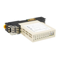
Category: Temperature Controller
|
Size: 3.02 MB
Table of Contents
Advertisement
Omron E5ZN Series Operation Manual (187 pages)
Brand: Omron
|
Category: Temperature Controller
|
Size: 1.27 MB
Table of Contents

OMRON E5ZN Series Manual (17 pages)
Modular Temperature Controller E5ZN Series
Brand: OMRON
|
Category: Temperature Controller
|
Size: 1.67 MB
Table of Contents
Advertisement

Omron E5ZN Series Manual (15 pages)
Brand: Omron
|
Category: Controller
|
Size: 1.36 MB
Table of Contents

OMRON E5ZN Series Brochure (4 pages)
E5ZN SERIES in-panel temperature control solutions
Brand: OMRON
|
Category: Temperature Controller
|
Size: 0.33 MB

Omron E5ZN Series Instruction Manual (2 pages)
Brand: Omron
|
Category: Temperature Controller
|
Size: 0.49 MB
Advertisement