Xerox Phaser 6115MFP Service Manual
Color laser multifunction product
Hide thumbs
Also See for Phaser 6115MFP:
- User manual (219 pages) ,
- Setup manual (75 pages) ,
- Quick use manual (17 pages)
Table of Contents
Advertisement
Quick Links
Advertisement
Table of Contents
Troubleshooting

Related Manuals for Xerox Phaser 6115MFP


Summary of Contents for Xerox Phaser 6115MFP
- Page 1 Service Manual 701P28980 Phaser 6115MFP ® Color Laser Multifunction Product...
- Page 3 Service Manual 701P28980 ® Phaser 6115MFP Color Laser Multifunction Product Warning The following servicing instructions are for use by qualified service personnel only. To avoid personal injury, do not perform any servicing other than that contained in the operating instructions, unless you are qualified to do so.
- Page 4 Copyright © 2008 Xerox Corporation. All Rights Reserved. Unpublished rights reserved under the copyright laws of the United States. Contents of this publication may not be reproduced in any form without permission of Xerox Corporation. Copyright protection claimed includes all forms of matters of copyrightable materials and information now allowed by statutory or judicial law or hereinafter granted, including without limitation, material generated from the software programs which are displayed on the screen such as styles, templates, icons, screen displays, looks, etc.
- Page 5 Caution: A personal injury hazard exists that may not be apparent. For example, a panel may cover the hazardous area. Danger: A personal injury hazard exists in the area where you see the sign. Phaser 6115MFP Multifunction Product Service Manual...
- Page 6 Symbols Marked on the Product Hot surface on or in the printer. Use caution to avoid personal injury. Do not touch the item. Use caution (or draws attention to a particular component). Refer to the manual(s) for information. Phaser 6115MFP Multifunction Product Service Manual...
- Page 7 Follow these guidelines to avoid injuring yourself or damaging the printer: Do not place any food or liquids on the printer. Turn off the printer and unplug all power cables before moving the printer. Phaser 6115MFP Multifunction Product Service Manual...
- Page 8 Total Satisfaction Guarantee. The Total Satisfaction Guarantee is available in the United States and Canada. Coverage may vary outside these areas; please contact your local representative for details. Phaser 6115MFP Multifunction Product Service Manual...
- Page 9 Handle IC’s and EPROM’s carefully to avoid bending pins. Pay attention to the direction of parts when mounting or inserting them on Printed Circuit Boards (PCB’s). Phaser 6115MFP Multifunction Product Service Manual...
- Page 10 CLASS 1 LASER PRODUCT The Phaser 6115MFP Multifunction Product is certified to comply with Laser Product Performance Standards set by the U.S. Department of Health and Human Services as a Class 1 Laser Product. This means that this product does not emit hazardous laser radiation;...
- Page 11 This printer uses heat to fuse the toner image to media. The Fusing Unit is VERY HOT. Turn the printer power off and wait at least 5 minutes for the Fusing Unit to cool before you attempt to service the unit or adjacent components. 5 min. Phaser 6115MFP Multifunction Product Service Manual...
- Page 12 Consult the dealer or an experienced radio/television technician for help. Any changes or modifications not expressly approved by Xerox could void the user's authority to operate the equipment. To ensure compliance with Part 15 of the FCC rules, use shielded interface cables.
- Page 13 European Union Xerox Corporation declares, under our sole responsibility, that the product to which this declaration relates is in conformity with the following standards and other normative documents: January 1, 1995: Low Voltage Directive 73/23/EEC as amended by 93/ 68/EEC.
- Page 14 Manual Organization The Phaser 6115MFP Multifunction Product Service Manual is the primary document used for repairing, maintaining, and troubleshooting the printer. Use this manual as your primary resource for understanding the operational characteristics of the printer and all available options. This manual describes specifications, theory, and the diagnosis and repair of problems occurring in the print engine and attached options.
-
Page 15: Table Of Contents
Phaser 6115MFP Front View (with Optional Sheet Feeder) ....... . . - Page 16 Misfeed at Duplex Option Paper Feed Section ..........4-14 Phaser 6115MFP Multifunction Product Service Manual...
- Page 17 Energy Save Mode..............6-9 Phaser 6115MFP Multifunction Product Service Manual...
- Page 18 Maintenance Mode Function Tree ............6-39 Phaser 6115MFP Multifunction Product Service Manual...
- Page 19 Imaging Unit ............... . 7-15 Phaser 6115MFP Multifunction Product Service Manual...
- Page 20 Exit Sensor (PL4.18.9) ............. . . 8-122 xviii Phaser 6115MFP Multifunction Product Service Manual...
- Page 21 PL 5.4 Feeder Wiring Harness ............9-62 Phaser 6115MFP Multifunction Product Service Manual...
- Page 22 PL 7.1 Xerox Supplies ........
-
Page 23: General Information
General Information In this chapter... Printer Introduction and Overview System Options System Specifications Chapter... -
Page 24: Printer Introduction And Overview
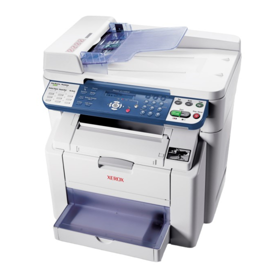
2400 x 600 dots-per-inch (dpi). The system features USB and 10/100baseT Ethernet ports. The Phaser 6115MFP provides a 200-sheet Tray 1 (MPT) from which specialty media, card stock, and envelopes are fed. Tray 1 (MPT) also supports manual feeding. -
Page 25: Phaser 6115 Mfp Rear View
General Information Phaser 6115 MFP Rear View Power Switch Duplex s6115-420 Phaser 6115MFP Multifunction Product Service Manual... -
Page 26: System Configurations
General Information System Configurations The Phaser 6115MFP Multifunction Product is available in two configurations. The main differences is the addition of the Duplex Unit to enable 2-sided printing. The following table lists both configurations. Configuration Features 6115N 6115D 5/20 5/20... -
Page 27: System Specifications
10%-80% RH @ 15° to 32° C/59° to 89° F to with water vapor no Humidity higher than 25.5 C/77.9° F 80% condition. Operating Range 0-2,500 meters (8,000 ft.) Altitude Transportation -20° C to +55° C/-4° to 131° F Range Temperature Transportation 30%-85% RH, non-condensing Range Humidity Phaser 6115MFP Multifunction Product Service Manual... -
Page 28: Product Specifications
USB device (High-speed mode 480 Mbps) interface Camera direct USB Host (Full-speed mode 12 Mbps) interface Network Ethernet 10/100 BaseT interface PSTN line (Fax Telephone line jack/External device jack RX/TX) OS compatibility Windows 98SE/Me/2000/XP/Server 2003 Phaser 6115MFP Multifunction Product Service Manual... - Page 29 / 16 to 24 lb.) Transparencies Thick stock (90 to 163 g/m / 25 to 40 lb.) Postcards Envelopes Letterhead Label stock (60-163 g/m /16-43 lb. bond) Glossy stock(163 g/m index max/110 lb. book max) Phaser 6115MFP Multifunction Product Service Manual...
- Page 30 Transparencies, thick stock, postcards, labels stock, and glossy stock, 50 sheets Envelopes, 10 sheets Machine Durability 200,000 prints or 5 years, whichever comes first Color to color Vertical: Average 0.12mm (0.005”) registration Horizontal: Average 0.12mm (0.005”) Phaser 6115MFP Multifunction Product Service Manual...
- Page 31 9 groups (50 destination stations for one group) Broadcast Available maximum 125 stations. (One-touch dial 9 stations, speed dial 100 stations, full dial 16 stations) Other Timer transmission, phone book, real time clock, auto supported redial, reduce/split, smoothing functions Phaser 6115MFP Multifunction Product Service Manual...
-
Page 32: Physical Dimensions And Clearances
72.6 cm (28.6 in.) 90.2 cm (35.5 in.) 10 cm 10 cm (3.9 in.) (3.9 in.) 10 cm (3.9 in.) 32 cm (12.6 in.) 80 cm (31.5 in.) 72.8 cm (28.7 in.) s6115-459 1-10 Phaser 6115MFP Multifunction Product Service Manual... -
Page 33: Adf Specifications
Power Requirements DC 5 V ± 5% Max. Power 12 W Consumption Dimensions 495 (W) × 581 (D) × 138 (H) mm (W) × 22 (H) × 5 (D) inch Weight 5.0 kg Phaser 6115MFP Multifunction Product Service Manual 1-11... -
Page 34: Control Panel Description
LED Indicators: LED State Printer State Green Ready to Print Flashing Yellow Warning (but can still print) Flashing Green In Power Saver mode or busy (receiving or processing data) Flashing Red Error; cannot print 1-12 Phaser 6115MFP Multifunction Product Service Manual... -
Page 35: Control Panel Display
Pressing the Display key will display the [TONER REMAINING] screen. Pressing the Cancel/C key will cause the Main screen to reappear. T O N E R R E M A I N I N G s6115-352 Phaser 6115MFP Multifunction Product Service Manual 1-13... -
Page 36: Main Engine Components
The following illustration provides a basic locator for the main system boards and power supplies. Engine Control Board Thermistor DC Power Supply 1 Control Panel Image Processor Board Fuser Connectors High Voltage Power Supply DC Power Supply 2 s6115-513 1-14 Phaser 6115MFP Multifunction Product Service Manual... -
Page 37: Motors And Fans Locator
The following illustration provides a basic locator for the main engine motors and fans. Scanner Cooling Fan Fusing Motor Main Motor Scanner Motor Ventilation Fan Developing Motor Rack Motor Power Supply Cooling Fan s6115-512 Phaser 6115MFP Multifunction Product Service Manual 1-15... -
Page 38: Sensors And Switches Locator
Fusing Paper Switch Loop Sensor Waste Toner Rack Near Full Positioning Detect Board Sensor Registration Temperature/ Sensor Humidity Sensor Tray 1 Paper Empty Sensor Transparency Sensor IDC Sensor 2nd Image Transfer Sensor s6115-510 1-16 Phaser 6115MFP Multifunction Product Service Manual... -
Page 39: Solenoids And Power Switch Locator
Solenoids and Power Switch Locator The following illustration provides a basic locator for the main system solenoids. Image Transfer Solenoid Cleaning Blade Solenoid Power Switch Tray 1 Paper Take-Up Solenoid Registration Roller Solenoid s6115-511 Phaser 6115MFP Multifunction Product Service Manual 1-17... -
Page 40: System Options
General Information System Options Phaser 6115MFP options include a 500-Sheet Feeder and a Duplex Unit. 500-Sheet Feeder (Tray 2) The 500-Sheet Feeder (Tray 2) increases the input capacity of the system. The feeder attaches below Tray 1 with four screws. Only one 500-Sheet Feeder is supported. - Page 41 Duplex Unit The Duplex Unit adds two-sided printing. The Duplex Unit attaches in back of the system using two twist locks. Electrical connection to the printer is made by an interface cable. s6115-391 Phaser 6115MFP Multifunction Product Service Manual 1-19...
-
Page 42: Consumables And Maintenance Parts
Maintenance Part Numbers Description Part number FUSING UNIT, 110V, PHASER 6120/6115mfp 126K23192 FUSING UNIT, 220V, PHASER 6120/6115MFP 126K23202 IMAGING UNIT, PHASER 6120/6115MFP 108R00691 TRANSFER ROLLER, PHASER 6120/6115MFP 059E05450 HARDWARE MAINTENANCE KIT, PHASER 6120/6115MFP 604K35500 1-20 Phaser 6115MFP Multifunction Product Service Manual... - Page 43 By front panel (Service) Pick roller none * For 4.5K/1.5K toner. Toner life calculations are based on 5% coverage. ** 45,000 images for continuous printing, shorter job length will shorten the imaging unit life. Phaser 6115MFP Multifunction Product Service Manual 1-21...
- Page 44 General Information 1-22 Phaser 6115MFP Multifunction Product Service Manual...
-
Page 45: Theory Of Operation
Theory of Operation In this chapter... Operational Overview of the Phaser 6115MFP Paper Path of the Printer Major Assemblies and Functions Sensors Chapter... -
Page 46: Operational Overview Of The Phaser 6115Mfp
(YMCK)], and places the toner image of each color onto print media producing full-color prints. Print Cycle The block diagram of the Phaser 6115MFP print cycle provides the sequence of events for the xerographic process and the paper flow into and out of the printer. - Page 47 The residual toner left on the surface of the Transfer Roller) is removed by an alternating DC charge that transfers the waste toner back to the Transfer Belt for collection by the Transfer Belt cleaning blade. 2nd Transfer Roller Transfer Belt s6115-095 Phaser 6115MFP Multifunction Product Service Manual...
-
Page 48: System Control
Scanner Unit Open/Close Sensor Laser unit DC Power Supply 1 Lower Feeder Unit Engine Control Board Duplex Unit Paper Pick-up/ Transport Control System Line Power Supply/ Image Process Fusing Image Bus Line High Voltage s6115-068 Phaser 6115MFP Multifunction Product Service Manual... -
Page 49: Paper Path Of The Printer
The print media is supplied from Tray 1 or the optional Tray 2, and is transported into the printer along the paper path as shown in the diagram. Output Tray Tray 1 (MPT) Tray 2 (Optional 500-Sheet Feeder) s6115-045 Automatic Document Feeder (ADF) Print Path ADF Tray s6115-047 Phaser 6115MFP Multifunction Product Service Manual... -
Page 50: Major Assemblies And Functions
The location of the system’s primary functional components is shown. s6115-044 Fusing Unit Toner Cartridges Duplex Unit Imaging Unit Transfer Roller Transfer Belt Tray 2 Feeder Scanner Tray 1 Feeder Auto Document Feeder (ADF) Laser Phaser 6115MFP Multifunction Product Service Manual... -
Page 51: Fusing Unit
The fusing speed is changed in two steps relative to the system speed, either at high speed (which is +2% of the system speed) or low speed (which is -2.5% of the system speed). Phaser 6115MFP Multifunction Product Service Manual... - Page 52 The sequence of these operations is repeated so that the fusing speed is changed automatically according to the loop length. This effectively compensates for the difference between the fusing speed and paper transport speed during image transfer. s6115-073 s6115-072 Phaser 6115MFP Multifunction Product Service Manual...
- Page 53 Print cycle (3), the set temperature is 189 C. If the Temperature/Humidity Sensor indicates a temperature of less than 60 C, the set temperature is increased to 184 C. Standby state (4), maintain the roller temperature at 180 C. Phaser 6115MFP Multifunction Product Service Manual...
- Page 54 After 20 minutes of inactivity, the standby state set temperature changes to 170 C if interior temperature is less than 20 C or 165 C if the interior temperature is 20 C or higher. 2-10 Phaser 6115MFP Multifunction Product Service Manual...
- Page 55 60 C or less letterhead More than 60 C Plain paper, 60 C or less letterhead 257 More than 60 C mm or less Thick stock, postcards, labels Transparencies _ Envelopes 194* Glossy stock Phaser 6115MFP Multifunction Product Service Manual 2-11...
- Page 56 Heater Lamp, thus forcibly turning it OFF. Engine Control Board Heater Lamp Thermistor Heating Roller Thermostat Hard Protection Circuit Fusing Pressure Roller Laser Safety Switch Fuser Wdt Watchdog Reset Circuit Triac Circuit Heater Remote ON/OFF Power Switch s6115-101 2-12 Phaser 6115MFP Multifunction Product Service Manual...
- Page 57 140 - 148 mm 5 ppm 5 ppm 3 ppm 3 ppm 149 - 182 mm 5 ppm 5 ppm 3 ppm 3 ppm 183 ~ 210 mm 5 ppm 5 ppm 5 ppm 3 ppm Phaser 6115MFP Multifunction Product Service Manual 2-13...
-
Page 58: Scanner
Original media size settings are made on the Control Panel. An error occurs following the print cycle if the correct media size is not selected on the Control Panel or loaded in the tray. 2-14 Phaser 6115MFP Multifunction Product Service Manual... -
Page 59: Laser Assembly
Scanner from opening. s6115-058 Laser Assembly The Laser Assembly in the Phaser 6115MFP printer has two laser diodes. The laser diode control circuitry adjusts the light intensity for each beam automatically. Image data is transmitted to the laser diodes in the Laser Assembly as digital signals. - Page 60 Photo Conductor Surface Beam A Beam A Beam B Beam B Photo Conductor Direction of Rotation of Photo Conductor G2 Lens Laser Diode G1 Lens Return Mirror Polygon Mirror s6115-076 2-16 Phaser 6115MFP Multifunction Product Service Manual...
- Page 61 The print start position in the FD direction is determined by the Image Write Start signal (TOD) that is output from the Image Processor Board and the length of the paper. The laser emission area is determined by the paper size. Phaser 6115MFP Multifunction Product Service Manual 2-17...
- Page 62 Theory of Operation The area of 4 mm on both the leading and trailing edges of the paper is, however, the void image area. /HSYNC /VIDEO /TOD /VIDEO s6115-041 2-18 Phaser 6115MFP Multifunction Product Service Manual...
-
Page 63: Imaging Unit
When the Main Motor is energized, it turns the drive gear, which in turn rotates the drum. Main Motor Photo Conductor s6115-071 The cleaning blade is pressed against the drum to remove excess toner. Waste toner is stored in the Imaging Unit. Phaser 6115MFP Multifunction Product Service Manual 2-19... - Page 64 An electrical charge is applied to the drum by an electrode mounted near the drum. This charge attracts toner from the Toner Cartridge developer roller. The image stabilization control process controls the grid voltage (Vg) applied to the electrode’s grid mesh. Grid Mesh s6115-049 2-20 Phaser 6115MFP Multifunction Product Service Manual...
-
Page 65: Toner Cartridge
To attract toner to the drum, a developing bias voltage (Vb) that includes both DC (-) and + AC components is applied to the developing roller during development. The AC component is applied only during Phaser 6115MFP Multifunction Product Service Manual 2-21... - Page 66 Seal Bias Contact Point Developing Bias Contact Point Regulator Blade Contact Points s6115-080 Developer Roller Drive The Developer Roller is driven by the Developing Motor and intermediate gears. Main Motor Photoconductor Developing Motor Developer Roller s6115-050 2-22 Phaser 6115MFP Multifunction Product Service Manual...
- Page 67 Theory of Operation When the Toner Cartridge Rack is stationery at the developing position, the Developer Roller drive gear meshes with intermediate gears allowing the Development Motor to engage the roller. Intermediate Gear s6115-051 Phaser 6115MFP Multifunction Product Service Manual 2-23...
-
Page 68: Toner Cartridge Rack
The cartridge replacement position refers to the position at which the Toner Cartridge Rack is stopped for replacement of the Toner Cartridge of a specific color of toner. 2-24 Phaser 6115MFP Multifunction Product Service Manual... - Page 69 Developing Position s6115-083 The cartridge replacement position is where the Toner Cartridge Rack is rotated 70 degrees from the developing position. For Developing of K 70° Cartridge Replacement Position K Developing Position s6115-084 Phaser 6115MFP Multifunction Product Service Manual 2-25...
- Page 70 Standby Rack is Rotated Y Development Rack is Rotated Position Step 5 Step 6 Step 7 Step 8 M Development Standby Rack is Rotated Rack is Rotated Position C Development K Development s6115-086 2-26 Phaser 6115MFP Multifunction Product Service Manual...
- Page 71 Position s6115-088 When a replacement request is made for a Toner Cartridge, the Toner Cartridge Rack is rotated 70 degrees from the depleted cartridges’ developing position through pulse control of the Rack Motor. Phaser 6115MFP Multifunction Product Service Manual 2-27...
-
Page 72: Transfer Belt
In addition to the Transfer Belt, a Transfer Roller (sometimes referred to as the 2nd Transfer Roller) transfers the composite image to the media for fusing. 2nd Transfer Roller Pressure Slider Pressure/Retraction Roller s6115-053 2-28 Phaser 6115MFP Multifunction Product Service Manual... - Page 73 Transfer Roller) are driven by the Main Motor. The Transfer Roller Clutch at one end of the (2nd) Transfer Roller engages the Main Motor drive. Main Motor Transfer Roller Clutch 2nd Transfer Roller Transfer Belt Drive Roller Transfer Belt Unit 1st Transfer Roller s6115-054 Phaser 6115MFP Multifunction Product Service Manual 2-29...
- Page 74 The Cleaning Blade is normally in contact with the Transfer Belt. Driven Roller Cleaning Blade Toner Collecting Screw s6115-089 Cleaning Blade retraction operations are driven by the Main Motor, Cleaning Blade Solenoid, pressure cam, lever, and Cleaning Blade Position Sensor. 2-30 Phaser 6115MFP Multifunction Product Service Manual...
- Page 75 Rotation of the drive gear is transmitted to the pressure cam. When the Cleaning Blade Solenoid is energized, the half-moon-shaped pressure cam rotates a half turn to push the lever forward to retract the Cleaning Blade. Phaser 6115MFP Multifunction Product Service Manual 2-31...
- Page 76 Two detection holes are punched in the Transfer Belt. The image write start position varies according to the media size. For A4 or smaller media, the image write start position, as determined by the sensor, is detection hole A. 2-32 Phaser 6115MFP Multifunction Product Service Manual...
-
Page 77: Transfer Roller
Transfer Solenoid is energized, drive from the Main Motor is transmitted to the Transfer Roller Clutch. Transfer Belt Main Motor 2nd Transfer Assy Pressure/Retraction Clutch 2nd Transfer Roller Pressure/Retraction Clutch 2nd Image Transfer Solenoid s6115-092 Phaser 6115MFP Multifunction Product Service Manual 2-33... - Page 78 Transfer Belt and the Transfer Roller Clutch rotates a half turn. This moves the Pressure Slider. When the Pressure Slider moves, the Transfer Assembly, which has been pushed up by the ribs on the Pressure Slider, lowers. 2-34 Phaser 6115MFP Multifunction Product Service Manual...
-
Page 79: Process Control
Parameter correction and control over the entire printing process is called “process control”. Two primary process control mechanisms are used by the system, Automatic Transfer Voltage Control (ATVC) and Automatic Image Density Control (AIDC). Phaser 6115MFP Multifunction Product Service Manual 2-35... - Page 80 LED and detects the reflected light returning from the Transfer Belt. The light emitted from the LED is controlled so that the reflected light density is constant. 2-36 Phaser 6115MFP Multifunction Product Service Manual...
- Page 81 IDC Sensor measures the density of the pattern and sends the measured result to the controller for gradation adjustment. AIDC Sensor 1st Transfer Roller 2nd Transfer Roller Developing Charging Developing Bias Grid Bias AIDC Control ATVC Temperature/ Humidity Sensor s6115-102 Phaser 6115MFP Multifunction Product Service Manual 2-37...
- Page 82 Leak Detection Control Amount Of Toner Sticking Reflectance AIDC Intensity Control Measurement Control Reflectance Laser Intensity Control Measurement Control Control Of The Maximum Amount Of Toner Sticking Laser Intensity Control G Correction Control s6115-103 2-38 Phaser 6115MFP Multifunction Product Service Manual...
-
Page 83: Temperature/Humidity Sensor
It is also used for image stabilization, transfer ATVC, and fusing temperature control. Note There is a Control Panel command which obtains environmental temperature and humidity levels. However, this command is for internal use only and not available from the service menus. s6115-064 Phaser 6115MFP Multifunction Product Service Manual 2-39... -
Page 84: System Thermal Regulation
The Power Supply Cooling Fan runs at full-speed for: A predetermined period of time after the Power Switch is turned On A specified period of time representing the end of Energy Saver mode 2-40 Phaser 6115MFP Multifunction Product Service Manual... - Page 85 The Scanner Supply Fan runs at half-speed: At the end of a print cycle (half-speed rotation after a predetermined period of time needed for full-speed rotation) During half-speed rotation under any condition other than above Phaser 6115MFP Multifunction Product Service Manual 2-41...
-
Page 86: Waste Toner Collection
The Waste Toner Full Sensor detects a near full condition within the Imaging Unit waste toner reservoir. Two agitating augers are used in the reservoir to provide the maximum waste toner storage capacity. A waste toner near full 2-42 Phaser 6115MFP Multifunction Product Service Manual... -
Page 87: Tray 1 Feeder
When the LED light is unblocked following Imaging Unit replacement, the waste toner full condition is reset. Tray 1 Feeder Tray 1 Pick Roller Tray 2 No Tray 2 Pick Solenoid Paper Sensor s6115-060 Phaser 6115MFP Multifunction Product Service Manual 2-43... - Page 88 Lift Cam is rotated, which raises the Lift Plate. This allows the media to be taken up and fed in by the Pick Roller. Main Motor Tray 1 Pick Clutch Pick Roller Tray 1 Pick Solenoid s6115-055 2-44 Phaser 6115MFP Multifunction Product Service Manual...
- Page 89 When there is media loaded in the tray, the actuator drops into the tray, unblocking the sensor. When media runs out, the actuator raises, blocking the sensor. Phaser 6115MFP Multifunction Product Service Manual 2-45...
- Page 90 When the Registration Sensor is activated, the signal from the Transparency Sensor is also read to determine the media type. If the Transparency Sensor signal is High, Transparency film is in the registration section. 2-46 Phaser 6115MFP Multifunction Product Service Manual...
- Page 91 Registration Sensor, the system displays an error message on the Control Panel. The sheet causing the size error continues through the print process and is output to the tray. Operations for subsequent sheets are specified from the controller. Phaser 6115MFP Multifunction Product Service Manual 2-47...
-
Page 92: Exit Tray
Media is transported from the Fuser to the Exit Tray using the Exit Roller. the The Exit Sensor monitors the Media output. Exit Sensor Exit Roller Actuator s6115-061 The Fusing Motor drives the Exit Roller. 2-48 Phaser 6115MFP Multifunction Product Service Manual... -
Page 93: Automatic Document Feeder (Adf)
Document Feeder. The stopper is lowered in the standby state and raised when the document is taken up and fed in. A Separation Pad limits the number of sheets picked to one. Phaser 6115MFP Multifunction Product Service Manual 2-49... - Page 94 The Pick Roller transports the original up to the Take-up Roller. s6115-110 ADF Transport Operation When the sheet obstructs the ADF Feed Sensor, the Transport Roller, driven by the ADF Motor, turns to move the original to the document scanning position. s6115-111 2-50 Phaser 6115MFP Multifunction Product Service Manual...
- Page 95 ADF Output Tray. s6115-112 ADF Interlock The ADF contains a magnet at its edge that activates a switch located in the Scanner to indicate the position of the ADF. Magnet Switch s6115-066 Phaser 6115MFP Multifunction Product Service Manual 2-51...
-
Page 96: Duplex Unit
The print engine’s Exit Roller, typically driven by the Fusing Motor during one- sided operations, feeds media into the Duplex Option. For duplex operation, a lever disengages the Fusing Motor from the Exit Roller, and engages the Duplex Reverse Motor. 2-52 Phaser 6115MFP Multifunction Product Service Manual... - Page 97 Paper Loop Sensor has been activated. This drives the Registration Roller. When the Registration Roller is driven, the paper is conveyed into the machine. Phaser 6115MFP Multifunction Product Service Manual 2-53...
- Page 98 8th page of the original on the fourth sheet of paper. The third sheet of paper waits at the Duplex take-up position until the fourth sheet of paper is subjected to a switchback sequence. The process repeats until the print job is complete. 2-54 Phaser 6115MFP Multifunction Product Service Manual...
-
Page 99: 500-Sheet Feeder Unit
It ensures that only one sheet of paper is fed in at time. The Pick Solenoid is controlled by the system through the Feeder Control Board mounted in the feeder. Coupling gear PF Drive Board Paper Empty Sensor Paper Pick-up Solenoid s6115-035 Phaser 6115MFP Multifunction Product Service Manual 2-55... - Page 100 When the tray is empty, the actuator drops into the slit in the Lift Plate blocking the sensor PF Drive Board Paper Empty Sensor At Paper Empty Condition Under Normal Conditions s6115-036 2-56 Phaser 6115MFP Multifunction Product Service Manual...
-
Page 101: Sensors
When the sensing area is vacant, nothing is between the arms of the sensor, light falls on the photo-receptor sending the signal High. If the light is interrupted, the photo-transistor goes Low. Phaser 6115MFP Multifunction Product Service Manual 2-57... -
Page 102: Microswitches
Thermistors have a known value of resistance whose value varies with temperature. Used primarily in the Fuser for temperature sensing. Sensor Layout Exit Tray Full Sensor Exit Sensor Fusing Paper Loop Sensor Registration Sensor s6115-350 2-58 Phaser 6115MFP Multifunction Product Service Manual... -
Page 103: Error Codes And Messages
Error Codes and Messages In this chapter... Overview of Error Messages Index of Error and Warning Messages Messages, Codes, and Procedures Jam Error Procedures Chapter... -
Page 104: Overview Of Error Messages
Fuser temperature low error CALL 1A Fuser temperature high error CALL 1B Fuser Thermistor error CALL 21 Transparency Detect Sensor error CALL 23 Waste Toner Full Detection Sensor error CALL 24 Fuser temperature resistance error Phaser 6115MFP Multifunction Product Service Manual... -
Page 105: Other Error/Warning Messages
Paper empty error in Printing LOAD PAPER(xYYY) PAPER SIZE ERROR Paper size error in printing RESET PAPER(xYYY) MEDIA TYPE ERROR Paper type error CHANGE xyyz->XYYZ MEMORY FULL Memory full in printing PRESS ANY KEY Phaser 6115MFP Multifunction Product Service Manual... - Page 106 COVER *CAUTION* DUPLEX COVER OPEN *CAUTION* CLOSE DUPLEX COVER *CAUTION* SCANNER UNIT OPEN *CAUTION* CLOSE SCANNER UNIT DOC FEED COVER OPEN CLOSE DOC FEED COVER PAPER EMPTY LOAD PAPER(xYYY) OUTPUT TRAY FULL REMOVE PAPER Phaser 6115MFP Multifunction Product Service Manual...
- Page 107 030524120 is an example for phone number (as in 030524120 Tokyo) *REDIAL ALL FAILED* 030524120 is an example for phone number (as in 030524120 Tokyo) *HANG UP THE PHONE* 030524120 is an example for phone number (as in 030524120 Tokyo) Phaser 6115MFP Multifunction Product Service Manual...
- Page 108 CWIS or MCC prevent changes from the front panel ADMINISTERED BY PC STD 100% LINE PROBLEM Fax line problem STD 100% CHECK LINE REGISTERED! GROUP An error occurs if Group dial was selected when inputting the destination for Hook function. Phaser 6115MFP Multifunction Product Service Manual...
-
Page 109: Messages, Codes, And Procedures
This section correlates the output of the printer’s diagnostic aids and provides the location of the troubleshooting procedure to correct reported errors. Phaser 6115MFP Multifunction Product Service Manual... -
Page 110: Error Message Summary
101H Scanner Motor Malfunction 101H 3-29 102H Faulty Scanner Exposure Lamp 102H 3-30 Power Supply Errors Machine is Not Energized 3-32 Control Panel Indicators Do Not Light 3-33 Fusing Heaters Do Not Operate 3-34 Phaser 6115MFP Multifunction Product Service Manual... -
Page 111: Using The Troubleshooting Procedures
FG (frame ground) in place of any SG pin or test point. Before measuring voltages make sure the printer is switched On, the Imaging Unit and the paper trays are in place, and the interlock switch is actuated, unless a troubleshooting procedure instructs otherwise. Phaser 6115MFP Multifunction Product Service Manual... - Page 112 Unless otherwise specified, the following voltage tolerances are used within this section: Stated Measured +3.3 VDC +3.135 to +3.465 VDC +5.0 VDC +4.75 to +5.25 VDC +24.0 VDC +21.6 to +26.4 VDC 0.0 VDC Less than +0.5 VDC 3-10 Phaser 6115MFP Multifunction Product Service Manual...
-
Page 113: Jam Error Procedures
Step 2. Are the connections properly seated? Power up the system. Complete Go to Step 3. Does the system operate correctly? Replace the board and power up the Complete system (page 8-57). Phaser 6115MFP Multifunction Product Service Manual 3-11... -
Page 114: Flash Rom Malfunction
Step 2. Is the connection properly seated? Power up the system. Go to Step 3. Does the system operate correctly? Replace the board and power up the Complete system (page 8-57). 3-12 Phaser 6115MFP Multifunction Product Service Manual... -
Page 115: Main Motor Malfunction
Step 3. Check the operation of the Main Motor. Replace the Go to Step 4. Is the motor faulty? motor (page 8-93). If the problem persists, go to Step 4. Phaser 6115MFP Multifunction Product Service Manual 3-13... -
Page 116: 0Bh Ventilation Fan Motor Malfunction
Step Action and Questions Check the Ventilation Fan Motor Go to Step 2. Reseat the connector CN2 for proper connection. connector. If Is the connector seated properly? the problem persists, go to Step 2. 3-14 Phaser 6115MFP Multifunction Product Service Manual... -
Page 117: 0Ch Power Supply Cooling Fan Malfunction
To avoid the potential of electric shock, ensure the power to the printer is off and the power cord is disconnected from the wall outlet prior to performing each step of the following troubleshooting procedure. Phaser 6115MFP Multifunction Product Service Manual 3-15... -
Page 118: Polygon Motor Malfunction
To avoid the potential of electric shock, ensure the power to the printer is off and the power cord is disconnected from the wall outlet prior to performing each step of the following troubleshooting procedure. 3-16 Phaser 6115MFP Multifunction Product Service Manual... -
Page 119: Laser Malfunction
To avoid the potential of electric shock, ensure the power to the printer is off and the power cord is disconnected from the wall outlet prior to performing each step of the following troubleshooting procedure. Phaser 6115MFP Multifunction Product Service Manual 3-17... -
Page 120: Second Image Transfer Pressure/Retraction Failure
To avoid the potential of electric shock, ensure the power to the printer is off and the power cord is disconnected from the wall outlet prior to performing each step of the following troubleshooting procedure. 3-18 Phaser 6115MFP Multifunction Product Service Manual... -
Page 121: Cleaning Blade Pressure/Retraction Failure
15H Cleaning Blade Pressure/Retraction Failure Faulty sensor, solenoid, or cleaning blade retraction. Applicable Status Code 15H: Cleaning Blade Pressure/Retraction Failure Initial Actions Remove power from the system and reboot. Print a test page. Phaser 6115MFP Multifunction Product Service Manual 3-19... - Page 122 Check the Cleaning Blade Solenoid. Is it Go to Step 5. Replace the operational? solenoid (page 8-105). If the problem persists, go to Step 5. Replace the Engine Control Board Complete. (page 8-57). 3-20 Phaser 6115MFP Multifunction Product Service Manual...
-
Page 123: Transfer Belt Rotation Failure
Replace the Engine Control Board Complete If the problem (page 8-57) and reboot. persists, go to Is the system operational? Step 3. Replace the Transfer Belt Unit Complete. (page 8-33). Phaser 6115MFP Multifunction Product Service Manual 3-21... -
Page 124: Rack Rotation Failure
Step 3. Check the Engine Control Board Go to Step 4. Reseat the connector P/J5. connector. If the Is the connector seated properly. problem persists, go to Step 4. 3-22 Phaser 6115MFP Multifunction Product Service Manual... -
Page 125: Heating Roller Warmup Failure
Abnormally High Heating Roller Temperature 1BH Faulty Thermistor Faulty thermistor in the Fusing Unit. Applicable Status Code 1BH: Faulty Thermistor Initial Actions Remove power from the system and reboot. Print a test page. Phaser 6115MFP Multifunction Product Service Manual 3-23... - Page 126 If the problem persists, go to Step 4. Replace the Engine Control Board Complete Go to Step 5. (page 8-57). Is the system operational? Replace the DC Power Supply 1 Complete (page 8-60). 3-24 Phaser 6115MFP Multifunction Product Service Manual...
-
Page 127: Faulty Transparency Sensor
Check the Transparency Sensor at P/J40 Go to Step 3. Replace the pin 6. Is the sensor on? sensor (page 8-117). If the problem persists, go to Step 3. Replace the Engine Control Board Complete. (page 8-57). Phaser 6115MFP Multifunction Product Service Manual 3-25... -
Page 128: Faulty Waste Toner Near Full Detection Board
Go to Step 4. the system operational? Replace the WTDTB/LED Board Complete Go to Step 5. (page 8-70). Is the system operational? Replace the Engine Control Board Complete. (page 8-57). Is the system operational? 3-26 Phaser 6115MFP Multifunction Product Service Manual... -
Page 129: 2Ah Faulty Nvram Data
Go to Step 2. Did this resolve the problem? Check the NVRAM on the Engine Control Replace the Replace the Board. Engine Control machine. Board Was the NVRAM chip properly installed? (page 8-57). Phaser 6115MFP Multifunction Product Service Manual 3-27... -
Page 130: Scanner Cooling Fan Motor Malfunction
Step 2. Check the Engine Control Board Go to Step 3. Reseat the connector MP/J1 for proper connection. connector. If the Is the connector seated properly? problem persists, go to Step 3. 3-28 Phaser 6115MFP Multifunction Product Service Manual... -
Page 131: Scanner Motor Malfunction
To avoid the potential of electric shock, ensure the power to the printer is off and the power cord is disconnected from the wall outlet prior to performing each step of the following troubleshooting procedure. Phaser 6115MFP Multifunction Product Service Manual 3-29... -
Page 132: Faulty Scanner Exposure Lamp
Replace the DC Power Supply 1 Complete (page 8-60). 102H Faulty Scanner Exposure Lamp Incorrect printer exposure. Applicable Status Code 102H: Faulty Scanner Exposure Lamp Initial Actions Remove power from the system and reboot. Print a test page. 3-30 Phaser 6115MFP Multifunction Product Service Manual... - Page 133 Complete Go to Step 5. Is the system operational? Replace the Engine Control Board Complete Go to Step 6 (page 8-57). Is the system operational? Replace the Image Processor Board Complete. (page 8-55). Phaser 6115MFP Multifunction Product Service Manual 3-31...
-
Page 134: Machine Is Not Energized
(page 8-60). If problem persists, go to Step 3. Is DC24V and DC5V being applied to PJ2 Complete Go to Step 4. on the Engine Control Board? Replace the Engine Control Board Complete (page 8-57). 3-32 Phaser 6115MFP Multifunction Product Service Manual... -
Page 135: Control Panel Indicators Do Not Light
Step 2. Are fuses (F1 and F2) on the DC Power Go to Step 3. Replace the DC Supply 1conducting? Power Supply 1 (page 8-60). If the problem persists, go to Step 3. Phaser 6115MFP Multifunction Product Service Manual 3-33... -
Page 136: Fusing Heaters Do Not Operate
CN3 on the DC Power Supply 1? wiring from PG1 to CN1. If NOTE The top and front cover should be in problem the closed position at this time. persists, go to Step 2. 3-34 Phaser 6115MFP Multifunction Product Service Manual... -
Page 137: Fax/Transmission Error Codes
The transmission error after “Phase-C” performs redial only one time. Transmission is cancelled when an error occurs again. (can change in Soft When an error occurs by ADF TX, transmission is canceled without redial. (Picure here, Perhaps - with explanation). Phaser 6115MFP Multifunction Product Service Manual 3-35... - Page 138 13TX and RX machines both have different “machine ID (FAX model ID)” code in RSD. 003F Remote side TSI not programmed in machine one touch or speed dial directory. 3-36 Phaser 6115MFP Multifunction Product Service Manual...
- Page 139 Did not detect control channel signal after received RCP frame within 6 seconds. 005F Did not detect silence after sending JM signal for polling TX function. 0060 There are no bulletin files to be polled in V.34. Phaser 6115MFP Multifunction Product Service Manual 3-37...
- Page 140 Remote side CSI number not defined in machine one touch or speed dial directory. 008F Modem not ready to receive V.34 data during 6 seconds after receiving CFR signal. 0090 Called side document not ready for our polling. 3-38 Phaser 6115MFP Multifunction Product Service Manual...
- Page 141 Modem not ready within 10 second after entering primary channel in V.34. 00BD Can not detect correct V.21 or JM signal after detected FSK frequency. 00BE Remote side no document to be polled after V8 handshaking. Phaser 6115MFP Multifunction Product Service Manual 3-39...
- Page 142 Did not receive any response in RR response procedure after sending PPS_NULL. 00E4 At phase-D, transmitting unit sends out PPS_MPS 3 times consecutively but no answer. 00E5 Received incorrect response after sending PPS_MPS. 3-40 Phaser 6115MFP Multifunction Product Service Manual...
- Page 143 Did not receive any response in RR response procedure after sending EOR_EOM. 00FC Did not receive any response after sending CTC. 00FD Can’t speed down to lower speed in ECM mode. 00FE Memory full for transmission. 00FF Redial all fail. Phaser 6115MFP Multifunction Product Service Manual 3-41...
- Page 144 Error Codes and Messages 3-42 Phaser 6115MFP Multifunction Product Service Manual...
-
Page 145: General Troubleshooting
General Troubleshooting In this chapter... Servicing Instructions Main Print Engine Troubleshooting Auto Document Feeder Troubleshooting Lower Feeder Unit Troubleshooting Duplexer Troubleshooting Chapter... -
Page 146: Servicing Instructions
2. Use the Disassembly Procedures to replace the part. Step 5 - Final Check Test the printer to be sure you have corrected the initial problem and verify there are no additional problems present. Phaser 6115MFP Multifunction Product Service Manual... -
Page 147: Main Print Engine Troubleshooting
Try loading paper from a fresh ream, fan the paper, and then insert into the tray or flip existing paper over. Clean the Feed Rollers with a clean, dry, lint-free wipe. Troubleshoot the Paper Pick Assembly. Phaser 6115MFP Multifunction Product Service Manual... -
Page 148: Misfeed At Paper Feed Section
(page 8-116). Check the Tray 1 Paper Pick-Up Solenoid Go to Step 4. Replace the operation at P/J18 (pin 18). Is the solenoid solenoid operational. (page 8-102). Replace the Engine Control Board Complete. (page 8-57). Phaser 6115MFP Multifunction Product Service Manual... -
Page 149: Misfeed At 2Nd Transfer Section
P/J14 (Pin 6). Is the sensor operational. sensor (page 8-114). Check the Registration Roller Solenoid at Go to Step 5. Replace the P/J11 (Pin 4). Is the solenoid solenoid operational? (page 8-104). Replace the Engine Control Board Complete (page 8-57). Phaser 6115MFP Multifunction Product Service Manual... -
Page 150: Misfeed At Fusing Section
Go to Step 4. Replace the the sensor operational? sensor (page 8-122). Check the Registration Roller Solenoid at Go to Step 5. Replace the P/J11 (pin 4). Is the solenoid solenoid operational? (page 8-104). Phaser 6115MFP Multifunction Product Service Manual... -
Page 151: Misfeed At Exit Section
If Are the connectors seated properly? the problem persists, go to Step 2. Check the Exit sensor at P/J6 (pin 3). Is Go to Step 3. Replace the the sensor operational? sensor (page 8-122). Phaser 6115MFP Multifunction Product Service Manual... -
Page 152: Undefined Misfeed
If the problem persists, go to Step 2. Check the Image Processing Board Go to Step 3. Reseat the connectors. connectors. If Are the connectors seated properly? the problem persists, go to Step 3. Phaser 6115MFP Multifunction Product Service Manual... -
Page 153: Auto Document Feeder Troubleshooting
Does the selected paper meet proper media specifications? and go to Step Clean the ADF Pick Roller (page 7-9). Go to Step 3. Complete. Does the problem persist? Replace the ADF Unit (page 8-11). Complete Phaser 6115MFP Multifunction Product Service Manual... -
Page 154: Misfeed At The Document Transport Section
Does the selected paper meet proper media specifications? and go to Step Clean the ADF Pick Roller (page 7-9). Go to Step 3. Complete. Does the problem persist? Replace the ADF Unit (page 8-11). Complete 4-10 Phaser 6115MFP Multifunction Product Service Manual... -
Page 155: Misfeed At The Document Exit Section
Does the selected paper meet proper media specifications? and go to Step Clean the ADF Pick Roller (page 7-9). Go to Step 3. Complete. Does the problem persist? Replace the ADF Unit (page 8-11). Complete Phaser 6115MFP Multifunction Product Service Manual 4-11... -
Page 156: Lower Feeder Unit Troubleshooting
(page 8-116). Check the Paper Pick-up Solenoid at Go to Step 4. Replace the connector solenoid P/J22 (Pin 4). Is the solenoid (page 8-131). operational? Replace the Engine Control Board Complete (page 8-57). 4-12 Phaser 6115MFP Multifunction Product Service Manual... -
Page 157: Duplexer Troubleshooting
J2 (Pin 5 - 8). Is the motor operational? motor (page 8-146). Replace the Duplex Option (page 8-134). Complete Go to Step 4. Does the problem persist? Replace the Engine Control Board Complete (page 8-57). Phaser 6115MFP Multifunction Product Service Manual 4-13... -
Page 158: Misfeed At Duplex Option Paper Feed Section
Go to Step 4. connector CN7B (Pin 5). Is the sensor operational? Replace the Duplex Option (page 8-134). Go to Step 4 Complete Does the problem persist? Replace the Engine Control Board Complete. (page 8-57). 4-14 Phaser 6115MFP Multifunction Product Service Manual... -
Page 159: Print-Quality Troubleshooting
Print-Quality Troubleshooting In this chapter... Print-Quality Problems Overview Print Quality Troubleshooting Summary Scanner System Image Processing System Fusing System Chapter... -
Page 160: Print-Quality Problems Overview
Inspect the visible surfaces of all rollers for obvious defects. If no defects are observed, replace the Imaging Unit, Developer Assembly, Transfer Roller, and Fusing Unit one at a time until the defect is eliminated. Phaser 6115MFP Multifunction Product Service Manual... -
Page 161: Defects Associated With Specific Printer Components
See “Imaging Unit” on page 7-15 for instructions on how to clean the Imaging Unit rollers. Transfer Roller Toner on the back side of the printed page (simplex mode) Light Prints Repeating Defects Fusing Unit Hot or Cold Offsetting Repeating Defects Phaser 6115MFP Multifunction Product Service Manual... - Page 162 OPC Drum Rollers 74 mm (2.91 in.) IDT Rollers 132 mm (5.20 in.) Transfer Roller Transfer Roller 64 mm (2.52 in.) Fusing Unit Heat Roller 83 mm (3.26 in.) Belt 94 mm (3.70 in.) Phaser 6115MFP Multifunction Product Service Manual...
-
Page 163: Print Quality Troubleshooting Summary
5-28 Blurred Image 5-30 Black or Blank Copy 5-31 Incorrect Color Image Registration 5-32 Fusing Unit Poor Fusing Performance or Offset 5-34 Brush Effect or Blurred Image 5-35 Back Marking 5-36 Uneven Pitch 5-37 Phaser 6115MFP Multifunction Product Service Manual... -
Page 164: Automatic Document Feeder (Adf) Print Quality Problems
Initial Actions Verify the media used is supported by this printer. Verify the media settings are correct at the Control Panel. Troubleshooting Reference Table Applicable Parts Example Print Scanner Unit, PL3.1.1 Blank Print Black Print Phaser 6115MFP Multifunction Product Service Manual... -
Page 165: Low Image Density Or Rough Image
Low Image Density or Rough Image The overall image density is too light. Initial Actions Verify the media used is supported by this printer. Verify the media settings are correct at the Control Panel. Phaser 6115MFP Multifunction Product Service Manual... - Page 166 Does the defect still occur? Reseat all connectors and Replace the Scanner Complete. cables between the Scanner Unit (page 8-25). Unit and the Image Processor Board, and then make another copy. Does the defect still occur? Phaser 6115MFP Multifunction Product Service Manual...
-
Page 167: Foggy Background
Does the defect occur on it is a problem within scanner system. the printed output? the print image system. Go to Go to Step 2. page 5-24 to continue troubleshooting the print image process. Phaser 6115MFP Multifunction Product Service Manual... -
Page 168: Black Streaks Or Bands
Verify the media used is supported by this printer. Verify the media settings are correct at the Control Panel. Troubleshooting Reference Table Applicable Parts Example Print Scanner Unit, PL3.1.1 Chrysanthemum x morifolium Vertical Stripes 5-10 Phaser 6115MFP Multifunction Product Service Manual... -
Page 169: Black Spots
Does the defect still occur? Black Spots The background image of all copies includes black spots. Initial Actions Verify the media used is supported by this printer. Verify the media settings are correct at the Control Panel. Phaser 6115MFP Multifunction Product Service Manual 5-11... - Page 170 Thoroughly clean both the document glass and CVT window. Does the defect still occur? 5-12 Phaser 6115MFP Multifunction Product Service Manual...
-
Page 171: White Streaks Or Bands
Verify the media used is supported by this printer. Verify the media settings are correct at the Control Panel. Troubleshooting Reference Table Applicable Parts Example Print Scanner Unit, PL3.1.1 Chrysanthemum x morifolium Chrysanthemum x morifolium Random Light Stripes Vertical Blank Lines Phaser 6115MFP Multifunction Product Service Manual 5-13... -
Page 172: Uneven Pitch
The print on the copy is on an uneven skew from the original. Initial Actions Verify the media used is supported by this printer. Verify the media settings are correct at the Control Panel. 5-14 Phaser 6115MFP Multifunction Product Service Manual... - Page 173 Open and Close the ADF and verify it closes completely. Does the defect still occur? Phaser 6115MFP Multifunction Product Service Manual 5-15...
-
Page 174: Image Processing System
Are there scratches on the Unit (page 8-13). photo conductor surface? Is the outside of the surface Carefully clean the Go to Step 3. dirty? surface. If the problem persists, go to Step 3. 5-16 Phaser 6115MFP Multifunction Product Service Manual... -
Page 175: White Or Colored Lines And Bands In Scan Direction
Horizontal lines or bands in the copy indicate problems in the scan direction. Initial Actions Verify the media used is supported by this printer. Verify the media settings are correct at the Control Panel. Phaser 6115MFP Multifunction Product Service Manual 5-17... - Page 176 If the scratched? transfer belt is scratched, replace the unit. Is the Transfer Roller Replace the roller Go to Step 7. scratched? (page 8-84). If the problem persists, go to Step 7. 5-18 Phaser 6115MFP Multifunction Product Service Manual...
-
Page 177: Uneven Density In The Feed Direction
Applicable Parts Example Print Imaging Unit, PL4.15.9 Transfer Belt Unit, PL4.15.5 High Voltage Unit, PL4.19.6 Laser Unit, PL4.14.1 Toner Cartridge (See consumables parts list) Chrysanthemum x morifolium Color Uneven or Wrong (Scan Direction) Phaser 6115MFP Multifunction Product Service Manual 5-19... -
Page 178: Uneven Density In The Scan Direction
The density of the print along the width of the copy is inconsistent. Initial Actions Verify the media used is supported by this printer. Verify the media settings are correct at the Control Panel. 5-20 Phaser 6115MFP Multifunction Product Service Manual... - Page 179 (page 8-33) and go to Step 5. Has the problem been Complete Replace the following eliminated? units, listed in order, until problem is eliminated: Toner Cartridge (page 7-11) High Voltage Unit (page 8-50) Phaser 6115MFP Multifunction Product Service Manual 5-21...
-
Page 180: Low Image Density
Is the Transfer Belt Unit Clean the unit with a Go to Step 5. dirty or scratched? soft cloth. If the belt is scratched, replace the Transfer Belt Unit (page 8-33). 5-22 Phaser 6115MFP Multifunction Product Service Manual... -
Page 181: Gradation Reproduction Failure
Verify the media settings are correct at the Control Panel. Troubleshooting Reference Table Applicable Parts Example Print Laser Unit, PL4.14.1 Imaging Unit, PL4.15.9 Transfer Belt Unit, PL4.15.5 High Voltage Unit, PL4.19.6 Toner Cartridge (See consumables parts list) s6115-242 s6115-241 Phaser 6115MFP Multifunction Product Service Manual 5-23... -
Page 182: Foggy Background
(page 8-50) Foggy Background Background image of copy is distorted or foggy. Initial Actions Verify the media used is supported by this printer. Verify the media settings are correct at the Control Panel. 5-24 Phaser 6115MFP Multifunction Product Service Manual... - Page 183 Has the problem been Complete Replace the following eliminated? units, listed in order, until problem is eliminated: Laser Unit (page 8-15) Toner Cartridge (page 7-11) Transfer belt Unit (page 8-33) Phaser 6115MFP Multifunction Product Service Manual 5-25...
-
Page 184: Poor Color Reproduction
Step 3. Has the problem been Complete Replace the following eliminated? units, listed in order, until problem is eliminated: Transfer Belt Unit (page 8-33) Engine Control Board (page 8-57) High Voltage Unit (page 8-50) 5-26 Phaser 6115MFP Multifunction Product Service Manual... -
Page 185: Void Areas And White Spots
Is the transfer belt dirty or If the surface is dirty, Go to Step 5. scratched? wipe the surface clean with a soft cloth. If the transfer belt is scratched, replace the unit (page 8-33). Phaser 6115MFP Multifunction Product Service Manual 5-27... -
Page 186: Colored Spots
Verify the media settings are correct at the Control Panel. Troubleshooting Reference Table Applicable Parts Example Print Imaging Unit, PL4.15.9 Toner Cartridge (see Consumables Parts List) Transfer Belt Unit, PL4.15.5 Fusing Unit, PL4.18.12 Chrysanthemum x morifolium White Portion is Colored 5-28 Phaser 6115MFP Multifunction Product Service Manual... - Page 187 Go to Step 8. Is the Fuser Roller dirty or Unit (page 8-36). If the scratched? problem persists, go to Step 8. Has the problem been Complete Replace the problem eliminated? toner cartridge (page 7-11). Phaser 6115MFP Multifunction Product Service Manual 5-29...
-
Page 188: Blurred Image
Step 3. Has the problem been Complete Replace the following eliminated? units, listed in order, until problem is eliminated: Toner Cartridge (page 7-11) Laser Unit (page 8-15) Imaging Unit (page 8-13) 5-30 Phaser 6115MFP Multifunction Product Service Manual... -
Page 189: Black Or Blank Copy
Imaging Unit Step 4. connected properly? Are connectors and cables Go to Step 5. Reseat the connectors. If securely connected to the the problem persists, go High Voltage Unit? to Step 5. Phaser 6115MFP Multifunction Product Service Manual 5-31... -
Page 190: Incorrect Color Image Registration
Verify the media settings are correct at the Control Panel. Troubleshooting Reference Table Applicable Parts Example Print Transfer Belt Unit, PL4.15.5 Imaging Unit, PL4.15.9 Transfer Roller, PL4.16.3 Laser Unit, PL4.14.1 Chrysanthemum x morifolium Color Registration 5-32 Phaser 6115MFP Multifunction Product Service Manual... - Page 191 (page 8-13). If the problem persists, go to Step 5 Has the problem been Complete Replace the following eliminated? units, listed in order, until problem is eliminated: Engine Control Board (page 8-57) Laser Unit (page 8-15) Phaser 6115MFP Multifunction Product Service Manual 5-33...
-
Page 192: Fusing System
Clean the original glass Close the levers. If the the green fuser separator and reprint the test problem persists, go to levers in the correct sheet. Then, go to Step Step 3. position? 5-34 Phaser 6115MFP Multifunction Product Service Manual... -
Page 193: Brush Effect Or Blurred Image
Replace with paper Go to Step 2. Is the paper damp or the that meets the incorrect media for the specifications for the printer? printer. If the problem persists, go to Step 2. Phaser 6115MFP Multifunction Product Service Manual 5-35... -
Page 194: Back Marking
Verify the media settings are correct at the Control Panel. Troubleshooting Reference Table Applicable Parts Example Print Transfer Belt Unit, PL4.15.5 Transfer Roller, PL4.16.3 Fusing Unit, PL4.18.12 High Voltage Unit, PL4.19.6 Toner on Back of Print 5-36 Phaser 6115MFP Multifunction Product Service Manual... -
Page 195: Uneven Pitch
Uneven Pitch The pitch along the scan direction is uneven or inconsistent. Initial Actions Verify the media used is supported by this printer. Verify the media settings are correct at the Control Panel. Phaser 6115MFP Multifunction Product Service Manual 5-37... - Page 196 Step 6. Has the problem been Complete Replace the following eliminated? units, listed in order, until problem is eliminated: Toner Cartridge (page 7-11) Transfer Belt Unit (page 8-33) 5-38 Phaser 6115MFP Multifunction Product Service Manual...
-
Page 197: Adjustments And Print Function Settings
Adjustments and Print Function Settings In this chapter... Adjust Function Procedures Service Mode Functions Maintenance Mode Functions Chapter... -
Page 198: Adjust Function Procedures
The Developing Unit has a strong magnetic field. Keep watches and measuring instruments away from it. Take care not to damage the PC Drum with a tool or similar device. Do not touch IC pins with bare hands. Phaser 6115MFP Multifunction Product Service Manual... -
Page 199: Service Mode Functions
Pressing the Menu/Select key at this level will execute the selected command. Note Pressing the Cancel key at any level will bring you up to the previous command level. Exiting: Press the Stop key to exit. Phaser 6115MFP Multifunction Product Service Manual... -
Page 200: Service Mode Function Tree
CCD Sub Regis ADF Sub Zoom ADF Main Regist ADF Sub Regist DMAX 1st Trans. Vol. 2nd Trans. Vol. VPP Offset ROHS Flicker Special 3 Counter Total Print Total Scan Printer Jam ADF Jam Trouble s6115-355 Phaser 6115MFP Multifunction Product Service Manual... - Page 201 Error Code List Protocol List 8 Fixed Zoom Change 9 Factory Test Signal Test Relay Test Sensor Test Dial Test Volume Test Panel Buzzer Test RAM Test 10 Clear Data SRAM Clear Memory Clear s6115-542 Phaser 6115MFP Multifunction Product Service Manual...
-
Page 202: System Default
V.17: 14400, 12000, 9600, 7200 V.29: 9600, 7200 V.27: 4800, 2400 Send Level Function: PSK/FSK signal output level. Setting: -17 to -10 dBm, -9 dBm (default), or -8 to -2 dBm Receive Level Function Reception sensitivity level. Phaser 6115MFP Multifunction Product Service Manual... -
Page 203: Dtmf Level
-17 to -12 dBm, -11 dBm (default), or -10 to -2 dBm ECM Mode Function: Select error correction mode. Setting: ON (default): When an error occurs during communication, re-send the frame where the error occurs. OFF: Any error is ignored during communication. Phaser 6115MFP Multifunction Product Service Manual... -
Page 204: Coding Scheme
Protocol Report Function: Print communication report. Choose one from among the following. Settings: OFF (default): Disable T.30 communication report. ON: Print T.30 communication report. ON ERROR: Print T.30 communication report when an error occurs. Phaser 6115MFP Multifunction Product Service Manual... -
Page 205: Gdi Time-Out
0 (5sec), 1 (10sec), 2 (20sec), 3 (30sec), 4 (40sec), 5 (50sec), 6 (default), or (60sec) Energy Save Mode Function: Set to either activate Energy Save mode when print job receiving, or specify panel operation for a given period. Setting: ON (default) Phaser 6115MFP Multifunction Product Service Manual... -
Page 206: Adjustment
Enter the [2. ADJUST] menu in the service mode. Select [PRN MAIN REGIST] of [2. ADJUST] and press the Menu Select key twice. 6-10 Phaser 6115MFP Multifunction Product Service Manual... -
Page 207: Prn Sub Regist
Adjust the width of C in the printed test pattern 1 so that the following specification is met. Specification: 20 ± 2.5 mm Adjustment Range: -6.00 (-6.00 mm, ~ 0 (0 mm default), ~ +6.00 (+6.00 mm) Step: 0.33 mm Phaser 6115MFP Multifunction Product Service Manual 6-11... -
Page 208: Ccd Main Zoom
After the [PRN MAIN REGIST] and [PRN SUB REGIST] adjustments have been performed Adjustment: Adjust the width of D in the copy of the test pattern 1 so that the following specification is met. 6-12 Phaser 6115MFP Multifunction Product Service Manual... - Page 209 Instructions If the width of D in the test pattern is longer than the specified width..Decrease the setting. If the width of D in the test pattern is shorter than the specified width..Increase the setting. Phaser 6115MFP Multifunction Product Service Manual 6-13...
-
Page 210: Ccd Sub Zoom
Select [CCD SUB ZOOM] of [2. ADJUST] and press the Menu Select key. Place the test pattern 1 on the Original Glass and make a test copy. Note The test pattern 1 should be positioned vertically. 6-14 Phaser 6115MFP Multifunction Product Service Manual... -
Page 211: Ccd Main Regist
Adjust the amount that widths A and B in the copy of the test pattern 1 so that the following specification is met. 0 ± 2.0 mm Adjustment Range: -5.0 (-5.0 mm), ~ 0.0 (0.0 mm default), ~ +5.0 (+5.0 mm) Step: 0.5 mm Phaser 6115MFP Multifunction Product Service Manual 6-15... -
Page 212: Ccd Sub Regist
If the width of B is less than the width of A..Decrease the setting. CCD Sub Regist Function: To adjust for variations in the accuracy of Scanner parts and their mounting accuracy by varying the scanning start position in the sub-scanning direction. 6-16 Phaser 6115MFP Multifunction Product Service Manual... - Page 213 Check that the width of C in the copy of the test pattern are shifted. If the width of C is out of specification, adjust it according to the following procedure: Press the Menu Select key. Phaser 6115MFP Multifunction Product Service Manual 6-17...
-
Page 214: Adf Sub Zoom
Calculation: (1 - Width of E in the document ÷ Width of E in the copy) × 100 If the width of E is out of specification, adjust it according to the following procedure. 6-18 Phaser 6115MFP Multifunction Product Service Manual... -
Page 215: Adf Main Regist
Enter the [2. ADJUST] menu in the service mode. Select [ADF MAIN REGIST] of [2. ADJUST] and press the Menu Select key. 4. Place the test pattern 1 into the Automatic Document Feeder and make a test copy. Phaser 6115MFP Multifunction Product Service Manual 6-19... -
Page 216: Adf Sub Regist
Adjustment Range section of the Auto Document Feeder Unit. DMAX (Manufacturing Only) Function: To adjust the density of each color. 1st Transfer Voltage (Manufacturing Only) Function: To adjust the voltage applied to the Transfer Roller for each color. 6-20 Phaser 6115MFP Multifunction Product Service Manual... -
Page 217: 2Nd Transfer Voltage (Manufacturing Only)
To adjust the developing when an image problem (uneven density) occurs in an environment of low atmospheric pressure in places such as at high altitudes. Adjustment range: STEP0 (0V default), STEP1 (-100V, STEP2 (-200V), STEP3 (-300V) Phaser 6115MFP Multifunction Product Service Manual 6-21... -
Page 218: Rohs
Eliminates flickers of a room fluorescent light when it occurs due to power source use environment or similar reason. Use: Use when the fluorescent light flickers due to power source use environment or similar reason. Setting: OFF (default) 6-22 Phaser 6115MFP Multifunction Product Service Manual... -
Page 219: Counter Functions
Displays the number of monochrome printed pages produced. Use: When checking the number of monochrome printed pages produced Color Print Function: Displays the number of color printed pages produced. Use: When checking the number of color printed pages produced. Phaser 6115MFP Multifunction Product Service Manual 6-23... -
Page 220: Total Scan
Displays the number of misfeeds that have occurred in the Auto Document Feeder Unit. Use: When checking for the number of misfeeds that have occurred in the Auto Document Feeder Unit. Trouble Function: 6-24 Phaser 6115MFP Multifunction Product Service Manual... -
Page 221: Configuration
Displays the version of the NIC firmware. When to Use: When checking for the Firmware version. Main Ram Size Displays the size of the main memory. When to Use: When checking for the memory size. Phaser 6115MFP Multifunction Product Service Manual 6-25... -
Page 222: Bb Cpld Version
Select the paper tray. Press the Start key to begin testing paper feeding. Press the Stop key to stop testing paper feeding. Note Do not use this procedure when warming up the printer. 6-26 Phaser 6115MFP Multifunction Product Service Manual... -
Page 223: Print Test Pattern
Pattern 2 Function: To print the test pattern for halftones and gradations. Use: When checking density and pitch irregularities, or when checking reproducibility of gradations. Procedure: Select the paper tray. Select the [PATTERN2]. Phaser 6115MFP Multifunction Product Service Manual 6-27... -
Page 224: Adf Feed Test
This command is currently inoperable. Refer to the User’s Guide for using this command in the customer mode. Function: To check for dirt in the scanning section of the Automatic Document Feeder. Use: If spots appear in the copies 6-28 Phaser 6115MFP Multifunction Product Service Manual... -
Page 225: Park Scan Head
Enter the user service mode. Select [Park Scan Head] and press the Menu Select key. The Scanner Unit moves to the home position when the start key is pressed. Turn OFF the machine's main switch. Phaser 6115MFP Multifunction Product Service Manual 6-29... -
Page 226: Fax Reg Copy Test
Stores a FAX image in memory and provides a printed copy. Use: To test the creation of a FAX image. Procedure: Press the Menu key to begin the FAX Reg copy test. Command delivers a printed copy to the output tray. 6-30 Phaser 6115MFP Multifunction Product Service Manual... -
Page 227: Scan Test
RX IN MEMORY MAIN RAM SIZE ROM ID Retrieving the Service Data List: Enter the [SERVICE MODE]. Select [REPORT] and press the Menu Select key. Select [SERVICE DATA LIST] and press the Menu Select key. Phaser 6115MFP Multifunction Product Service Manual 6-31... - Page 228 Maker: NSF frame maker code Tell.: Remote side or TX side telephone number for that transaction Retrieving the Error Log History List: Enter the [SERVICE MODE]. Select [REPORT] and press the Menu Select key. 6-32 Phaser 6115MFP Multifunction Product Service Manual...
-
Page 229: Error Code List
MODE: Communication speed and ECM mode RESULT: Communication result TX: T.30 command sent by local Fax RX: T.30 command received from remote Fax DATA: T.30 frame that include address & control & Data Phaser 6115MFP Multifunction Product Service Manual 6-33... -
Page 230: Fixed Zoom Change
EXPANSION2 141% 141% to 199% Inch Values Setting name Initial fixed zoom ratio Setting range REDUCTION2 51% to 64% REDUCTION1 65% to 99% EXPANSION1 129% 101% to 153% EXPANSION2 154% 154% to 199% 6-34 Phaser 6115MFP Multifunction Product Service Manual... -
Page 231: Factory Test
Checks the operation of the display and all indicators and buttons. When the panel buzzer test is finished, press the panel reset key twice. RAM Test Tests reading and writing of RAM memory. Phaser 6115MFP Multifunction Product Service Manual 6-35... -
Page 232: Clear Data Functions
Some setting values are not included any of these reports or lists. Be sure to make a note of them separately. After [SRAM CLEAR] has been executed, make necessary entries of data again based on the setting values recorded. 6-36 Phaser 6115MFP Multifunction Product Service Manual... -
Page 233: Memory Clear
Some setting values are not included any of these reports or lists. Be sure to make a note of them separately. After [MEMORY CLEAR] has been executed, make necessary entries of data again based on the setting values recorded. Phaser 6115MFP Multifunction Product Service Manual 6-37... -
Page 234: Maintenance Mode Functions
Pressing the Menu/Select key at this level will execute the selected command. Note Pressing the Cancel key at any level will bring you up to the previous command level. Exiting: Press the Stop key to exit. 6-38 Phaser 6115MFP Multifunction Product Service Manual... -
Page 235: Maintenance Mode Function Tree
Transmit start speed setting. Settings: Choose the mode from among the following. V.3 (default): 33600 (default), 31200, 28800, 26400, 24000, 21600, 19200, 16800 V.17: 14400, 12000, 9600, 7200, V.29: 9600, 7200, V.27: 4800, 2400 Phaser 6115MFP Multifunction Product Service Manual 6-39... -
Page 236: Receive Speed
-49 to -44 dBm, -43 dBm, or -42 to -36 dBm. The default setting is -43 dBm. DTMF Level Function: Sets the Dual tone output level. Setting: -17 to -10 dBm, -9 dBm, or -8 to -2 dBm. The default setting is “-9 dBm”. 6-40 Phaser 6115MFP Multifunction Product Service Manual... -
Page 237: Cng Level
OFF: Any error is ignored during communication. Coding Scheme Function: Selects compression method in the TX/ RX modes. Settings: MMR: A compression method. MR: A compression method. MH: The simplest compression method. Phaser 6115MFP Multifunction Product Service Manual 6-41... -
Page 238: Toner Empty Report
OFF (default): Disable T.30 communication report. ON: Print T.30 communication report. ON (ERROR): Print T.30 communication report when an error occurs. 2 SVC Part Life Transfer Belt Function: Displays the remaining life of the transfer belt. 6-42 Phaser 6115MFP Multifunction Product Service Manual... -
Page 239: Fusing Unit
Displays the remaining life of the Fusing Unit. Use: Checks the remaining life of the maintenance service parts. Transfer Roller Function: Displays the remaining life of the Transfer Roller. Use: Checks the remaining life of the maintenance service parts. Phaser 6115MFP Multifunction Product Service Manual 6-43... -
Page 240: Reset Count
Use after the Fusing Unit is replaced. Procedure: Enter the Maintenance Mode and call [3. RESET COUNT] to the screen. Select [FUSER UNIT] and press the Menu Select key. Press the Menu Select key. 6-44 Phaser 6115MFP Multifunction Product Service Manual... -
Page 241: Transfer Roller
Enter the Maintenance Mode. Select [Park Scan Head] and press the Menu/Select key. The scanner unit moves to the home position when the start key is pressed. Turn OFF the machine's main switch. Phaser 6115MFP Multifunction Product Service Manual 6-45... -
Page 242: Additional Scanner Adjustment Procedures
Adjusts for variations in machining and installation accuracy of different Scanner parts. The adjustment varies the scanning zoom ratio in the main scanning direction. When to Use: When the original glass is replaced. When the scanner unit is with a new one. 6-46 Phaser 6115MFP Multifunction Product Service Manual... - Page 243 If dimension A on the copy falls outside the specified range: Increase the setting value if dimension A falls short of the specified range. Decrease the setting value if dimension A exceeds the specified range. Phaser 6115MFP Multifunction Product Service Manual 6-47...
-
Page 244: Scanner Fd Registration
Press the Menu/Select key, adjust using the +/- key, and then press the Menu/Select key to validate the setting. Repeat steps 5 to 7 until the measurement of dimension A falls within the specified range. 6-48 Phaser 6115MFP Multifunction Product Service Manual... -
Page 245: Scanner Function Setting Procedure
Use this procedure to lock in all scanner functions Open the Scanner unit. Then, inserting a pin or similar object into the hole at portion, lower the lock lever Lock Lever Pinhole s6115-360 Phaser 6115MFP Multifunction Product Service Manual 6-49... -
Page 246: Additional Adf Adjustment Procedures
Select [ADF FD MAGNIFY] of [1 ADJUST] and press the Menu/Select key. Load the test chart in the ADF and press the Start key. Measure the length of line A on the copy to check that it falls within the specified range. 6-50 Phaser 6115MFP Multifunction Product Service Manual... -
Page 247: Adf Cd Registration
Width A: 20 mm s6115-362 Enter the SERVICE MODE. Select [ADF CD REGIST] of [1 ADJUST] and press the Menu/Select key. Load the test chart in the ADF and press the Start key. Phaser 6115MFP Multifunction Product Service Manual 6-51... -
Page 248: Adf Fd Registration
When to Use: When a new Auto Document Feeder Unit is mounted. Specification: 20mm +/- 1.0mm Adjustment Range: The default setting is 0.00. Adjustment Range: -5.00 (-5.00 mm) ~ “0.00 (0.00 mm)” ~ +5.00 (+5.00 6-52 Phaser 6115MFP Multifunction Product Service Manual... -
Page 249: Leading Edge Skew Adjustment
Decrease the setting value if dimension B exceeds the specified range. Leading Edge Skew Adjustment Adjusts problems associated with leading skew images. When to Use: when image skew occurs. Specification: 10mm +/- 2.0mm Phaser 6115MFP Multifunction Product Service Manual 6-53... - Page 250 20 mm s6115-364 Align each copy sample as shown and check the deviation. If the deviation is outside the specified range, perform the adjustment within the specification range of 0 ± 1.0 mm. s6115-365 6-54 Phaser 6115MFP Multifunction Product Service Manual...
- Page 251 Loosen the one screw (wide top, 10mm) in the back to the right. s6115-366 If the deviation is as shown to the left, move the graduations of the duplexing document feeder to the front. Phaser 6115MFP Multifunction Product Service Manual 6-55...
- Page 252 Adjustments and Print Function Settings Tighten the screw that has been loosened in step 5. s6115-367 If the deviation is as shown to the left, move the graduations of the duplexing document feeder to the back. 6-56 Phaser 6115MFP Multifunction Product Service Manual...
- Page 253 Adjustments and Print Function Settings Tighten the screw that has been loosened in step 5. s6115-368 Phaser 6115MFP Multifunction Product Service Manual 6-57...
- Page 254 Adjustments and Print Function Settings 6-58 Phaser 6115MFP Multifunction Product Service Manual...
-
Page 255: Cleaning And Maintenance
Cleaning and Maintenance In this chapter... Service Maintenance Procedures Consumables/Routine Maintenance Items Cleaning Procedures Maintenance Replacement Procedures Chapter... -
Page 256: Service Maintenance Procedures
1,500 Standard- section (C, Y, M, K) capacity 4,500 High-capacity Imaging Unit Monochrome 45,000 (continuous printing) Monochrome 20,000 (3-4 pages per job) Full Color 11,250 (continuous printing) Full Color 10,000 (3-4 pages per job) Phaser 6115MFP Multifunction Product Service Manual... - Page 257 * Standard-Capacity Toner Cartridges (C,M,Y), High-Capacity Toner Cartridges (C,M,Y,K). ** In the Quality menu you can specify whether to continue or stop printing when there is a toner empty condition. Phaser 6115MFP Multifunction Product Service Manual...
-
Page 258: Cleaning Procedures
Vacuum loose toner from the printer interior using a Type II toner vacuum only. Remove and clean the paper trays. Clean all rubber rollers with a lint-free cloth slightly dampened with cold water. This section describes regular maintenance procedures. Phaser 6115MFP Multifunction Product Service Manual... -
Page 259: Paper Feed Roller
Do not leave the Imaging Unit removed for more than 15 minutes, and do not place the removed Imaging Unit in a location where it will be exposed to direct light (such as sunlight). Phaser 6115MFP Multifunction Product Service Manual... -
Page 260: Laser Window
Laser Window Pull the lever to release the Scanner Unit. Note The Scanner Unit cannot be opened with the Auto Document Feeder unit in the raised position. Open the Top Cover (page 8-13). Phaser 6115MFP Multifunction Product Service Manual... - Page 261 Remove the Imaging Unit (page 8-13). s6115-257 Position the removed Imaging Unit as shown below. Note Be sure to keep the Imaging Unit horizontal and place it where it will not become dirty. s6115-254 Phaser 6115MFP Multifunction Product Service Manual...
- Page 262 Cleaning and Maintenance Using a soft cloth dampened with alcohol, clean the Laser window. s6115-369 Phaser 6115MFP Multifunction Product Service Manual...
-
Page 263: 500-Sheet Feeder Paper Pick-Up Roller
Wipe the Paper Pick-up Roller clean of dirt using a soft cloth dampened with alcohol. s6115-370 ADF Pick Up Roller Open the Top Cover. Wipe the Pick-up Roller clean of dirt using a soft cloth dampened with alcohol. s6115-359 Phaser 6115MFP Multifunction Product Service Manual... -
Page 264: Adf Registration Roller
Wipe the Registration Rollers clean of dirt using a soft cloth dampened with alcohol. Rollers s6115-371 Duplexer Transport Roller Open the duplex door. Using a soft cloth dampened with alcohol, wipe the transport roller clean of dirt. s6115-372 7-10 Phaser 6115MFP Multifunction Product Service Manual... -
Page 265: Maintenance Replacement Procedures
Open the top cover (page 8-4). Open the front cover and make sure that the specific Toner Cartridge to be replaced is in the front. s6115-258 Phaser 6115MFP Multifunction Product Service Manual 7-11... - Page 266 Note When you use the remaining instructions to reinstall a new Toner Cartridge, do not let the cartridge stand on end or keep it in that position. Prepare a new Toner Cartridge. s6115-260 7-12 Phaser 6115MFP Multifunction Product Service Manual...
- Page 267 Cleaning and Maintenance Shake the cartridge a few times to distribute the toner. s6115-261 Remove the protective cover. s6115-262 Phaser 6115MFP Multifunction Product Service Manual 7-13...
- Page 268 Aligning the shaft on both sides of the Toner Cartridge with the rails in the machine, install the cartridge. Laser Unit Shutter Lever s6115-314 Press down on the Toner Cartridge until it snaps into place. Close the Front Cover. Close the Top Cover. 7-14 Phaser 6115MFP Multifunction Product Service Manual...
-
Page 269: Imaging Unit
Replacement Note Remember to re-install the fuse so the life counter will work. Phaser 6115MFP Multifunction Product Service Manual 7-15... - Page 270 Cleaning and Maintenance 7-16 Phaser 6115MFP Multifunction Product Service Manual...
-
Page 271: Service Parts Disassembly
Service Parts Disassembly In this chapter... Overview Of Disassembly Procedures Print Engine Disassembly Procedures Duplex Disassembly Procedures 500-Sheet Feeder Options Disassembly Procedures Chapter... -
Page 272: Overview Of Disassembly Procedures
Do not use excessive force to remove or install either a screw or a printer part. Warning Unplug the AC power cord from the wall outlet before removing any printer part. Phaser 6115MFP Multifunction Product Service Manual... -
Page 273: Fastener Types
Bold arrows in an illustration show direction of movement when removing or replacing a component. The notation “(self-tapping, plastic 10 mm)” or “(metal, 6 mm)” refer to the type of screw being removed. Note Provides information specific to the replacement of parts or assemblies. Phaser 6115MFP Multifunction Product Service Manual... -
Page 274: Cover Disassembly Procedures
Service Parts Disassembly Cover Disassembly Procedures Top Cover (PL4.1.3) Pull the lever of the Scanner Unit Cover to open. Caution Keep the platen lid closed or the lever will not operate. Handle s6115-263 Phaser 6115MFP Multifunction Product Service Manual... - Page 275 Pull the lever of the top cover and lift to open. Caution When working on the printer with the cover open, be careful not to touch the Transfer Belt. Top Cover Transfer Belt Unit s6115-043 Phaser 6115MFP Multifunction Product Service Manual...
-
Page 276: Rear Cover (Pl2.1.1)
Disconnect the ADF hookup cable. s6115-284 Remove 3 screws (metal, 10mm). Remove the cover. You may need to press in the top left and top right side of the cover to remove. Phaser 6115MFP Multifunction Product Service Manual... -
Page 277: Left Cover (Pl2.1.13)
Partially close the Top Cover to expose the tab. Caution Use care not to break the tab during removal and reinstallation of the Left Cover. Release the tab to remove the Left Cover. s6115-134 Phaser 6115MFP Multifunction Product Service Manual... -
Page 278: Right Cover (Pl2.1.10)
Open the Top Cover (page 8-4). Remove the Rear Cover (page 8-6). Remove 3 screws (metal, 10mm). Pull the cover slightly from the top-right side to release the tab. Remove the Right Cover. s6115-135 Phaser 6115MFP Multifunction Product Service Manual... -
Page 279: Tray 1 And Cover (Pl4.21.1)
Remove the Tray 1 cover lid (and any paper left in the tray). s6115-530 Push in on each side of the plastic tray to release and remove the Paper Holder. s6115-531 Gently pry one side of the Tray 1 cover hinge to remove the cover. s6115-286 Phaser 6115MFP Multifunction Product Service Manual... -
Page 280: Front Cover (Pl2.1.12)
When tightening the screws, make sure that there is no clearance between the machine frame and Front Cover. If there is any clearance, press the cover against the frame while tightening the screws. 8-10 Phaser 6115MFP Multifunction Product Service Manual... -
Page 281: Unit Disassembly Procedures
Caution NEVER disconnect and reconnect the ADF hookup cable with the power switch turned ON, as a damaged Image Processing Board could result. s6115-381 Make sure the Auto Document Feeder Unit is closed. Phaser 6115MFP Multifunction Product Service Manual 8-11... - Page 282 4. Perform a ADF FD MAGNIFY (page 6-50). 5. Perform a ADF CD REGIST (page 6-51). 6. Perform a ADF FD REGIST (page 6-51). 7. Perform a leading edge skew adjustment (page 6-53). 8-12 Phaser 6115MFP Multifunction Product Service Manual...
-
Page 283: Imaging Unit (Pl4.15.9)
Imaging Unit (PL4.15.9) Pull the lever to release the Scanner Unit. Open the Top Cover (page 8-4). Note The Scanner Unit cannot be opened with the Auto Document Feeder unit in the raised position. s6115-257 Phaser 6115MFP Multifunction Product Service Manual 8-13... - Page 284 Do not expose the Imaging Unit to light for more than 15 minutes, and do not place the unit in a location where it will be exposed to direct light (such as sunlight). 8-14 Phaser 6115MFP Multifunction Product Service Manual...
-
Page 285: Laser Unit (Pl4.14.1)
Remove the Left Cover (page 8-7). Remove the Right Cover (page 8-8). Remove the Front Cover (page 8-10). Remove the Scanner Unit (page 8-25). Remove two screws (metal, 10mm) and the fixing base foot. s6115-434 Phaser 6115MFP Multifunction Product Service Manual 8-15... - Page 286 Remove 2 screws (one metal, 10mm, and one metal, 12mm) from the top right cover. 12mm 10mm s6115-450 Lift and remove the top right cover. Note You may need to raise the Top Cover to allow for clearance when removing the top right cover. 8-16 Phaser 6115MFP Multifunction Product Service Manual...
- Page 287 Remove 9 screws (metal, 8mm) from the right frame. s6115-451 Disconnect the speaker wire, remove it from the retaining clamp, and remove the right frame. Remove the screw (metal, 10mm) from the metal bracket. s6115-452 Phaser 6115MFP Multifunction Product Service Manual 8-17...
- Page 288 Remove 1 screw (self-tapping, 10mm) to remove the harness cover. Wiring Clamp s6115-453 Disconnect the connector (P/J19) and the flat cable (P/J20) from the Engine Control Board. P/J20 Engine Control Board P/J19 s6115-308 8-18 Phaser 6115MFP Multifunction Product Service Manual...
- Page 289 Remove the clamps and cable ties to free the cables. Grab the handle of the Imaging Unit and remove. Note Be sure to keep the Imaging Unit horizontal and place it where it will not become dirty. Phaser 6115MFP Multifunction Product Service Manual 8-19...
- Page 290 Caution When rotating the rack, use care not to touch the Developing Rollers. Rack Release Lever Toner Cartridge Rack Toner Cartridge s6115-310 Hold onto the handle, pull it and remove the Toner Cartridge. 8-20 Phaser 6115MFP Multifunction Product Service Manual...
- Page 291 Do not leave the Imaging Unit or the cartridges removed for more than 15 minutes. Also, do not place the Imaging Unit or the Toner Cartridges in a location where it will be exposed to direct light (such as sunlight). s6115-311 Phaser 6115MFP Multifunction Product Service Manual 8-21...
- Page 292 Pull the 3 unplugged harnesses through the chassis. Press the Rack Release Lever and turn the toner rack so that the screw securing the Laser Unit to the chassis can be accessed through the hole in the metal cross plate. 8-22 Phaser 6115MFP Multifunction Product Service Manual...
- Page 293 Service Parts Disassembly Remove 3 screws (metal, 10mm) and the Laser Unit. Caution When you lift the Laser Unit free from the chassis, take care when pulling any connected cables through the routing holes. s6115-313 Phaser 6115MFP Multifunction Product Service Manual 8-23...
- Page 294 Reconnect the blue connector before you reinstall the cover. To reinstall the ribbon cable, loosen the lower tab on the plastic air duct to provide access to the route. Laser Unit Shutter Lever s6115-314 8-24 Phaser 6115MFP Multifunction Product Service Manual...
-
Page 295: Scanner Unit (Pl3.1.1)
Remove the ADF Unit (page 8-11). Remove 11 screws (metal, 8mm), disconnect the connector P/J21, and remove the Image Processing Board metal protective cover. Note Lift up on the metal hooks to remove. P/J21 s6115-426 Phaser 6115MFP Multifunction Product Service Manual 8-25... - Page 296 Service Parts Disassembly Remove 3 screws (metal, 8mm) to remove the LAN (and FAX Modem) board and protective film. Protective Film s6115-440 8-26 Phaser 6115MFP Multifunction Product Service Manual...
- Page 297 Service Parts Disassembly Remove 4 screws (metal, 8mm) to remove the NCU (Network Card) Board. s6115-445 Remove 3 screws (metal, 8mm) and two standoffs to remove the board holding bracket. s6115-427 Phaser 6115MFP Multifunction Product Service Manual 8-27...
- Page 298 Remove 1 screw (metal, 10mm) to remove the cable holding bracket. s6115-524 Disconnect connector CN10 and 2 flat cables from the Image Processor Board. CN10 P/J7 P/J6 s6115-447 Open 4 cable clamps to allow access to the wiring harnesses. 8-28 Phaser 6115MFP Multifunction Product Service Manual...
- Page 299 Service Parts Disassembly Disconnect 2 connectors (MP/J1 and MP/J4) from the Image Processing Board and pull the wiring harness out of the clamps. MP/J1 MP/J4 s6115-448 Open the Scanner Unit. Phaser 6115MFP Multifunction Product Service Manual 8-29...
- Page 300 Note Be sure to note the alignment notch of the latch when reinstalling. Note To unhook the tab, insert your finger into the hole below the hinge and push the cover outward. 8-30 Phaser 6115MFP Multifunction Product Service Manual...
- Page 301 Service Parts Disassembly Tabs s6115-467 Remove the left hinge C-clip and right hinge C-clip of the Scanner Unit. s6115-468 Phaser 6115MFP Multifunction Product Service Manual 8-31...
- Page 302 2. Perform an CCD SUB ZOOM (page 6-14) 3. Perform a CCD MAIN REGIST (page 6-15). 4. Perform a CCD SUB REGIST (page 6-16). 5. Scanner CD Registration (page 6-46). 6. Scanner FD Registration (page 6-48). 8-32 Phaser 6115MFP Multifunction Product Service Manual...
-
Page 303: Transfer Belt Unit (Pl4.15.5)
Pull the lever to release the Scanner Unit. Note Note that the Scanner unit cannot be swung up with the Auto Document Feeder Unit in its raised position. Handle s6115-263 Open the Top Cover (page 8-4). Phaser 6115MFP Multifunction Product Service Manual 8-33... - Page 304 Service Parts Disassembly Disconnect the connector. s6115-266 Remove the two shoulder screws (silver metal, 12mm). 8-34 Phaser 6115MFP Multifunction Product Service Manual...
- Page 305 Shoulder Screw s6115-267 To reinstall, reverse the order of removal. Note After the transfer belt unit has been replaced with a new one, reset the maintenance counter of the Transfer Belt Unit (page 6-44). Phaser 6115MFP Multifunction Product Service Manual 8-35...
-
Page 306: Fusing Unit (Pl4.18.12)
Remove 1 screw (metal, 8mm) and remove the Top Left Cover. Note You may need to raise or lower the Top Cover as necessary to allow for clearance. s6115-270 Disconnect two connectors (P/J6 and P/J7) from the Engine Control Board. s6115-271 8-36 Phaser 6115MFP Multifunction Product Service Manual... - Page 307 DC power supply 2 and protective cover. Note Depress the plastic release on CN11 to release the connector. Replacement Note When replacing, be sure to place the 2 cover tabs in the hook slots. Phaser 6115MFP Multifunction Product Service Manual 8-37...
- Page 308 Service Parts Disassembly Remove 1 screw (self-tapping, 10mm) to remove the Scanner Unit left cover. Tabs 8-38 Phaser 6115MFP Multifunction Product Service Manual...
- Page 309 Service Parts Disassembly Remove the left hinge C-clip and right hinge C-clip of the Scanner Unit to free the hinged arm. s6115-468 Note Be careful not to lose the C-clip. Phaser 6115MFP Multifunction Product Service Manual 8-39...
- Page 310 Remove 3 screws (metal, 8mm) shown in the inset below and 4 screws (6 mm) from the chassis to free and remove the left frame. s6115-276 Replacement Note Carefully place the hook on the tab when replacing the frame. 8-40 Phaser 6115MFP Multifunction Product Service Manual...
- Page 311 Unplug 2 Fuser connectors from the top. Note You can also gain access to the connectors through the metal frame. Fuser Connectors Black White s6115-133 Phaser 6115MFP Multifunction Product Service Manual 8-41...
- Page 312 Service Parts Disassembly Swing open the Fusing Unit gear cover. s6115-280 Remove 1 screw (self-tapping, 10mm) and remove the holder. s6115-281 8-42 Phaser 6115MFP Multifunction Product Service Manual...
- Page 313 Reinstall the Fuser Unit in the reverse order of the previous steps. When reinstalling the left cover after reinstalling the Fusing Unit, make sure that the harness of the Fusing Unit is located below the rib of the left cover. Phaser 6115MFP Multifunction Product Service Manual 8-43...
- Page 314 Replacement Note Be sure to route all wires and wiring harnesses in their original position and that all positioning tabs are secure. Caution Be sure not to over-tighten self tapping (plastic) screws. 8-44 Phaser 6115MFP Multifunction Product Service Manual...
-
Page 315: Paper Take-Up Unit (Pl4.20.1)
Remove the Rack Drive Assembly. See the removal procedure steps 4 to 6 when disassembling the “Developing Motor (PL4.13.8)” on page 98. Remove the Ventilation Fan Motor (page 8-96). Remove 1 screw (metal, 8mm) and unlock two tabs. Phaser 6115MFP Multifunction Product Service Manual 8-45... - Page 316 Disconnect the cooling fan wires from the Engine Control Board and unsnap the fan from the two hooks of the shroud. Hook s6115-529 unhook 2 tabs of the shroud to pull the fan free from the chassis. 8-46 Phaser 6115MFP Multifunction Product Service Manual...
- Page 317 2 screws (self-tapping, 10 mm) from the left side. Right Side Left Side s6115-316 Remove 1 screw (metal, 10mm) and the metal plate from the right side, rear of the printer. Phaser 6115MFP Multifunction Product Service Manual 8-47...
- Page 318 Remove the black plastic guide by pushing the locking tab on the right side, and then allow the guide to fall. s6115-528 Replacement Note Notice the orientation of the black plastic guide and reinstall it in the same orientation 8-48 Phaser 6115MFP Multifunction Product Service Manual...
- Page 319 Pull the tray forward until it rests underneath the cams on the take-up assembly. Using the lower alignment pin, as a reference, reinstall the unit into the printer. Reinstall the springs. Phaser 6115MFP Multifunction Product Service Manual 8-49...
-
Page 320: High Voltage Unit (Pl4.19.6)
Make sure the power switch is off and the cord is unplugged prior to starting this (or any other) disassembly procedure. Remove the Left Cover (page 8-7). Remove the DC Power Supply 2 (page 8-68). Remove 1 screw (metal, 8mm) and the bracket. s6115-439 8-50 Phaser 6115MFP Multifunction Product Service Manual... - Page 321 Service Parts Disassembly Remove 4 screws (metal, 8mm). s6115-303 Phaser 6115MFP Multifunction Product Service Manual 8-51...
- Page 322 Service Parts Disassembly Disconnect two connectors and remove the High Voltage Unit. s6115-304 Replacement Note Make sure that the High Voltage Unit fits underneath the tab as shown in the following illustration. s6115-141 8-52 Phaser 6115MFP Multifunction Product Service Manual...
-
Page 323: Disassembly/Assembly Procedures (Main Engine)
Open the Top Cover. Disconnect the connector from the Transfer Belt. Remove 3 screw caps and screws (metal, 8mm) from the Control Panel Cover. s6115-488 Disconnect the 2-wire ADF set switch connector (P/J701). P/J701 P/J702 s6115-489 Phaser 6115MFP Multifunction Product Service Manual 8-53... - Page 324 Service Parts Disassembly Loosen the plastic ribbon cable holder, and then disconnect the ribbon cable connector (P/J702). s6115-526 Remove the ground wire cable. Replace the Control Panel and Assembly. 8-54 Phaser 6115MFP Multifunction Product Service Manual...
-
Page 325: Image Processor Board (Pl4.19.1)
Remove 11 screws (metal, 8mm) and disconnect the connectors. Remove the cover of the Image Processor Board. P/J21 s6115-426 Remove the LAN (and FAX Modem) Board (page 8-72). Remove the Network Communication (NCU) Board (page 8-74). Phaser 6115MFP Multifunction Product Service Manual 8-55... - Page 326 Remove 2 screws (metal, 8mm) and two standoff screws to the Rear Panel. s6115-427 Release the 4 plastic cable restraints and disconnect all connectors. s6115-428 Remove 2 screws (metal, 8mm) and remove the bracket on the top portion of the Engine Control Board. 8-56 Phaser 6115MFP Multifunction Product Service Manual...
-
Page 327: Engine Control Board (Pl4.19.15)
Remove the Image Processing Board (page 8-55). Remove 11 screws (metal, 8mm) and disconnect the connectors. Remove the metal protective covering of the Image Processor Board. Remove 1 screw (metal, 8mm) and the connector protective bracket. Phaser 6115MFP Multifunction Product Service Manual 8-57... - Page 328 Disconnect all connections and flat cables from the Engine Control Board. Engine Control Board s6115-431 Remove 4 screws (metal, 8mm) and disconnect the connector from the image processing board. Remove the Engine Control Board. s6115-430 8-58 Phaser 6115MFP Multifunction Product Service Manual...
- Page 329 When removing the NVRAM from the old Engine Control Board and mounting it on the new Engine Control Board, be sure to align the NVRAM chip properly to the mounting socket. Notch Notch s6115-433 Phaser 6115MFP Multifunction Product Service Manual 8-59...
-
Page 330: Dc Power Supply 1 (Pl4.19.3)
Remove the Scanner Unit (page 8-25). Remove the NCU Board (page 8-74). Remove the Image Processor Board (page 8-55). Remove the Engine Control Board (page 8-57). Remove 2 screws (metal, 10mm) and the remaining printer foot. s6115-434 8-60 Phaser 6115MFP Multifunction Product Service Manual... - Page 331 DC power supply 2 and protective cover. Note Depress the plastic release on CN11 to release the connector. Replacement Note When replacing, be sure to place the two cover tabs in the hook slots. Phaser 6115MFP Multifunction Product Service Manual 8-61...
- Page 332 Disconnect 4 connectors and remove the Power Switch. Caution At reinstallation, make sure each connector is in its proper position. Color of connector Color of harness White Black Black White White White 8-62 Phaser 6115MFP Multifunction Product Service Manual...
- Page 333 Switch and remove the wire from 2 wiring clamps. Black White AC Connectors s6115-137 Remove the harness protective plate. s6115-302 Disconnect all AC power harnesses to free the left side brace. Note Remove the green grounding wire from the AC Unit. Phaser 6115MFP Multifunction Product Service Manual 8-63...
- Page 334 Remove 9 screws (metal, 8mm) and one 6mm screw (and washer), and free the left frame from the chassis. s6115-276 Replacement Note Carefully place the hook on the tab when replacing the frame. 8-64 Phaser 6115MFP Multifunction Product Service Manual...
- Page 335 Disconnect the speaker wire and remove it from the retaining clamp, then remove the right frame, leaving only the cross-member of the right frame. Caution Be careful in the following step when freeing the assembly from the wiring harnesses. Phaser 6115MFP Multifunction Product Service Manual 8-65...
- Page 336 Service Parts Disassembly Remove 9 screws (metal, 8mm) and pull the DC power supply assembly toward you. s6115-435 8-66 Phaser 6115MFP Multifunction Product Service Manual...
- Page 337 Disconnect 5 connectors from the DC Power Supply 1 board. P/J4 P/J6 P/J3 P/J5 P/J1 s6115-436 Phaser 6115MFP Multifunction Product Service Manual 8-67...
-
Page 338: Dc Power Supply 2 (Pl4.5.4)
Remove 3 screws (metal, 8mm), release two tabs, then remove the DC Power Supply 1. s6115-437 DC Power Supply 2 (PL4.5.4) Remove the Left Cover (page 8-7). Remove 1 screw (metal, 8mm). Remove 2 saddle harnesses and disconnect connectors CN2 and CN11 (see illustration). 8-68 Phaser 6115MFP Multifunction Product Service Manual... - Page 339 Service Parts Disassembly Remove the power supply cover plate. Hooks CN11 s6115-272 Remove 4 screws (metal, 8mm) and the DC Power Supply 2. s6115-438 Phaser 6115MFP Multifunction Product Service Manual 8-69...
-
Page 340: Waste Toner Near Full Detection Board/Led (Pl4.6.6)
Caution Use caution when unlocking the tab. ’ Shield Clamp s6115-305 Note When reinstalling the shield, make sure that no part of the wiring harness is wedged in the mechanism. s6115-306 8-70 Phaser 6115MFP Multifunction Product Service Manual... - Page 341 Service Parts Disassembly Unlock 3 tabs and disconnect the connector (P/J1) of the Waste Toner Near Full Detection Board/LED to remove. P/J1 s6115-307 Phaser 6115MFP Multifunction Product Service Manual 8-71...
-
Page 342: Lan (And Fax Modem) Board (Pl4.19.11)
Remove 11 screws (metal, 10mm) and disconnect the connector. Remove the protective covering of the Image Processing Board. Caution To avoid damage to the cover, use caution when unlocking the tabs. P/J21 s6115-426 8-72 Phaser 6115MFP Multifunction Product Service Manual... - Page 343 Remove 3 screws (metal, 8mm) from the LAN (and FAX Modem) board and disconnect the board from the connector. Replacement Note When reinstalling the board, be sure to reinstall the protective cover. Protective Film s6115-440 Phaser 6115MFP Multifunction Product Service Manual 8-73...
-
Page 344: Ncu (Network Card) Board (Pl4.19.14)
Remove the Left Cover (page 8-7). Remove 11 screws (metal, 10mm) and disconnect the connector. Remove the protective covering from the board. Caution When reinstalling the board, be sure to reinstall the protective covering. P/J21 s6115-426 8-74 Phaser 6115MFP Multifunction Product Service Manual... - Page 345 To provide access to the NCU board, first remove 3 screws (metal, 8mm) from the LAN (and FAX Modem) board and disconnect it from the connector. Note When reinstalling the board, be sure to reinstall the protective cover. Protective Film s6115-440 Phaser 6115MFP Multifunction Product Service Manual 8-75...
- Page 346 Service Parts Disassembly Remove the NCU board. s6115-445 8-76 Phaser 6115MFP Multifunction Product Service Manual...
-
Page 347: Ac Inlet Harness (Pl4.19.7)
Note that the Scanner Unit cannot be swung up with the Auto Document Feeder Unit in its raised position. s6115-257 Remove the Auto Document Feeder Unit (page 8-11). Remove the Scanner Unit (page 8-25). Phaser 6115MFP Multifunction Product Service Manual 8-77... - Page 348 Remove 1 screw (metal, 10mm) from the protective cover. Remove two clamps and disconnect two connectors (CN1 and CN11). Then, remove the DC power supply 2 protective cover from the hooks. Hooks CN11 s6115-272 8-78 Phaser 6115MFP Multifunction Product Service Manual...
- Page 349 Replacement Note At reinstallation, make sure of the correct position of each connector.. Connector Color Wire Color Connector Color Wire Color s6115-273 Color of connector Color of harness White Black Black White White White Phaser 6115MFP Multifunction Product Service Manual 8-79...
- Page 350 Remove 3 clamps and release the harness. s6115-274 Remove 3 screws (metal, 8mm) and the NCU board. Then, remove the protective film. Replacement Note Make sure to reinstall the protective film when reinstalling the board. Protective Film s6115-440 8-80 Phaser 6115MFP Multifunction Product Service Manual...
- Page 351 Service Parts Disassembly Disconnect 2 connectors (MPJ2, MPJ3) from the Image Processing Board. MP/J3 MP/J3 s6115-441 Phaser 6115MFP Multifunction Product Service Manual 8-81...
- Page 352 Service Parts Disassembly Remove 9 screws (metal, 10mm) and the left frame. s6115-276 Remove 1 screw (metal, 10mm) and remove the bracket. Remove 1 screw (metal, 12mm) and the ground. 8-82 Phaser 6115MFP Multifunction Product Service Manual...
- Page 353 Remove the clamp. Then, holding down the tabs, remove the AC Inlet Harness. Clamp s6115-443 Caution Never unplug the faston terminals from the Inlet. If the terminals are unplugged, do not use the AC Inlet Harness. Be sure to use a new harness. s6115-444 Phaser 6115MFP Multifunction Product Service Manual 8-83...
-
Page 354: Paper Feed Roller (Pl4.20.17)
Do not leave the Imaging Unit removed for more than 15 minutes, and do not place the removed Imaging Unit in a location where it will be exposed to direct light (such as sunlight). s6115-254 8-84 Phaser 6115MFP Multifunction Product Service Manual... - Page 355 Service Parts Disassembly Remove the Paper Feed Roller s6115-256 Phaser 6115MFP Multifunction Product Service Manual 8-85...
-
Page 356: Transfer Roller (Pl4.16.3)
Use care not to lose the two springs of the assembly. They can easily come off. Transfer Roller s6115-268 Remove the conductive material, gear (PL4.16.7), two springs (PL4.16.5), two holders (PL4.16.6), and two collars (PL4.16.2). 8-86 Phaser 6115MFP Multifunction Product Service Manual... - Page 357 Reassembly Procedures Align the spring with the post on the plastic housing. Make sure that the drive gear on the Transfer Roller is aligned with the coupling on the right side of the printer. Phaser 6115MFP Multifunction Product Service Manual 8-87...
- Page 358 Service Parts Disassembly Make sure that the spring action of the roller is working correctly. Replacement Note Ensure that the High-Voltage Bias Spring is making contact with the Transfer Roller Bias Contact Plate. s6115-184 8-88 Phaser 6115MFP Multifunction Product Service Manual...
-
Page 359: Tray 1 Separation Pad (Pl4.20.7)
When replacing the Separation Pad, reattach the spring to the new pad. Line the spring up with the locator tab, and then snap the pad into the slots. Push on the pad to confirm that the spring is moving correctly. s6115-143 Phaser 6115MFP Multifunction Product Service Manual 8-89... -
Page 360: Print Engine Motors And Fans Disassembly Preparation
Print Engine Motors and Fans Disassembly Preparation Use the following procedure to prepare for the disassembly of the: Top Right Cover Right Frame Main Motor Power Supply Cooling Fan Ventilation Fan Fusing Motor Remove the Scanner Unit (page 8-25). 8-90 Phaser 6115MFP Multifunction Product Service Manual... - Page 361 Service Parts Disassembly Remove 1 screw (metal, 10mm) and the Top Right Cover. 12mm 10mm s6115-450 Phaser 6115MFP Multifunction Product Service Manual 8-91...
- Page 362 Service Parts Disassembly Remove 9 screws (metal, 10mm) and the Right Frame. s6115-451 8-92 Phaser 6115MFP Multifunction Product Service Manual...
-
Page 363: Main Motor (Pl4.12.1)
Main Motor (PL4.12.1) Use the procedures for removing the right cover (page 8-8). Remove the Right Frame (page 8-90). Remove four screws (metal, 10mm), disconnect the connector, and remove the Main Motor. P/J34 s6115-318 Phaser 6115MFP Multifunction Product Service Manual 8-93... -
Page 364: Power Supply Cooling Fan Motor (Pl4.8.1)
Remove the Right Frame (page 8-90). Disconnect the connector (PJ4A) from the Engine Control Board. Engine Control Board P/J4A s6115-319 Remove 1 screw (metal, 8mm), bracket, and guide. s6115-452 Remove the wiring clamp. 8-94 Phaser 6115MFP Multifunction Product Service Manual... - Page 365 Service Parts Disassembly Remove 1 screw (metal, 8mm) and the harness cover. Wiring Clamp s6115-453 Unlock tabs and remove the Power Supply Cooling Fan Motor. Tabs s6115-320 Phaser 6115MFP Multifunction Product Service Manual 8-95...
-
Page 366: Ventilation Fan Motor (Pl4.8.2)
Remove the Right Frame (page 8-90). Remove 2 screws (metal, 8mm) and the Fan Cover Bracket. s6115-455 Remove the harness from the wiring clamp and disconnect the connector (CN2) of the Ventilation Fan Motor. 8-96 Phaser 6115MFP Multifunction Product Service Manual... - Page 367 Service Parts Disassembly Unlock the two hooks and remove the Ventilation Fan Motor from the 2 tabs. Note Notice the position of the fan for reassembly. Hooks Tabs Tabs s6115-322 Phaser 6115MFP Multifunction Product Service Manual 8-97...
-
Page 368: Fusing Motor (Pl4.11.1)
Be sure to use the original screws and that the gear is in place when reinstalling the motor. Developing Motor (PL4.13.8) Open the Top Cover (page 8-4). Remove the Right Cover (page 8-8). Remove the Front Cover (page 8-10). 8-98 Phaser 6115MFP Multifunction Product Service Manual... - Page 369 If the screw is not in the original position, make sure that the distance between the switch lever and switch case (with the switch in the actuated position) falls within the specified range. Specifications: 0.1 to 1.0 mm s6115-325 Phaser 6115MFP Multifunction Product Service Manual 8-99...
- Page 370 Note If difficult, depress the gear assembly first before pulling out. s6115-326 Remove 2 screws (metal, 10mm), disconnect the connector, and remove the Developing Motor. P/J31 s6115-327 8-100 Phaser 6115MFP Multifunction Product Service Manual...
-
Page 371: Rack Motor (Pl4.13.9)
Remove the Right Frame, which is Step 9 of the Laser Unit Removal procedures on page 8-15. Remove the Developing Motor (page 8-98). Remove 2 screws (metal, 10mm), disconnect the connector (P/J30), and remove the Rack Motor. P/J30 s6115-328 Phaser 6115MFP Multifunction Product Service Manual 8-101... -
Page 372: Print Engine Solenoids And Sensors
Then, remove the shield. Shield Clamp s6115-305 Caution When reinstalling the shield, make sure that no part of the harness is wedged in the mechanism. Remove 1 screw (metal, 8mm) and disconnect connector (CN2). 8-102 Phaser 6115MFP Multifunction Product Service Manual... - Page 373 When reinstalling the solenoid, place the back end of the solenoid into the chassis first. Then, apply a small amount of pressure on the actuator arm, sliding it in between the teeth of the gear assembly. s6115-330 Phaser 6115MFP Multifunction Product Service Manual 8-103...
-
Page 374: Registration Roller Solenoid (Pl4.12.3)
Reinstall the solenoid so that the clearance between the gear of the registration roller clutch and flapper falls within the specified range (1.0 ± 0.2 mm). 8-104 Phaser 6115MFP Multifunction Product Service Manual... -
Page 375: Cleaning Blade Solenoid (Pl4.11.2)
Remove the Right Frame (page 8-90). Remove 1 screw (metal, 8mm), disconnect the connector, and remove the Cleaning Blade Solenoid. Replacement Note When reinstalling, make sure the actuator is behind the gear. s6115-333 Phaser 6115MFP Multifunction Product Service Manual 8-105... -
Page 376: Image Transfer Solenoid (4.10.14)
Disconnect the connector (CN5) from the solenoid. Move the mylar sheet out of the way, and then remove 1 screw (metal, 8mm) and the Image Transfer Solenoid. Caution Be careful not the damage the mylar. s6115-335 8-106 Phaser 6115MFP Multifunction Product Service Manual... -
Page 377: Exit Tray Full Sensor (Pl4.1.7)
Pull the lever to release the Scanner Unit. Note Note that the Scanner Unit cannot be swung up with the Auto Document Feeder Unit in its raised position. Handle s6115-263 Open the Top Cover (page 8-4). Phaser 6115MFP Multifunction Product Service Manual 8-107... - Page 378 Service Parts Disassembly Disconnect the connector (CN1). s6115-266 Remove 2 shoulder screws (PL4.15.4). 8-108 Phaser 6115MFP Multifunction Product Service Manual...
- Page 379 Lift and slide the Transfer Belt Unit out of the metal slots to remove. Note When replacing the Transfer Belt Unit, use care not to touch the surface of the belt. A scratchy or dirty belt could result in image problems. Shoulder Screw Shoulder Screw s6115-267 Phaser 6115MFP Multifunction Product Service Manual 8-109...
- Page 380 Service Parts Disassembly Remove the plastic roller cover. s6115-490 Remove the plastic roller. s6115-491 8-110 Phaser 6115MFP Multifunction Product Service Manual...
- Page 381 Service Parts Disassembly Remove 6 plastic screws from the plastic sensor cover, exposing the sensor and actuator. s6115-492 Squeeze the tabs to remove the sensor. s6115-493 Phaser 6115MFP Multifunction Product Service Manual 8-111...
-
Page 382: Rack Positioning Sensor (Pl4.3.12)
Service Parts Disassembly Rack Positioning Sensor (PL4.3.12) Remove the ADF Unit (page 8-11). Remove the Scanner unit (page 8-25). Remove 1 screw (metal, 10mm) and the Top Right Cover. 12mm 10mm s6115-450 8-112 Phaser 6115MFP Multifunction Product Service Manual... - Page 383 Remove 9 screws (metal, 10mm) and the Right Frame. s6115-451 Using a flathead screwdriver, push in the plastic hook of the sensor holder. s6115-494 Pinch the plastic sides of the sensor to free and remove from the holder. Phaser 6115MFP Multifunction Product Service Manual 8-113...
-
Page 384: Fusing Paper Loop Sensor (Pl4.17.2)
Disconnect the 3-wire connector (P/J42). Remove a single screw (metal, 8mm), release the plastic hook on the left side of the actuator to remove. Note This step will also expose the actuator underneath the sensor. s6115-495 8-114 Phaser 6115MFP Multifunction Product Service Manual... - Page 385 Service Parts Disassembly Release the flexible plastic actuator from one side to remove. s6115-496 Phaser 6115MFP Multifunction Product Service Manual 8-115...
-
Page 386: Registration Sensor (Pl4.17.2)
Remove the Scanner Unit (page 8-25). Remove the Transfer Belt Unit (page 8-33). Disconnect the 3-wire connector (P/J39). P/J39 s6115-505 Remove 1 screw (metal, 8mm) to remove the sensor. Pinch the plastic release hook to remove the actuator. 8-116 Phaser 6115MFP Multifunction Product Service Manual... -
Page 387: Transparency Sensor (Pl4.17.16)
Remove the Scanner Unit (page 8-25). Remove the Transfer Belt Unit (page 8-33). Remove 1 screw (metal, 8mm) to remove the sensor. P/J40 s6115-506 Pinch the plastic release hook to remove the sensor and actuator. Phaser 6115MFP Multifunction Product Service Manual 8-117... -
Page 388: Temperature/Humidity Sensor (Pl4.20.37)
Rotate the printer on its back and remove the C-clip. s6115-336 Remove the clip on the left side of the tray. From the right side of the tray, lift the tray free from the “boss.” 8-118 Phaser 6115MFP Multifunction Product Service Manual... - Page 389 Push in the tab that secures the housing to the frame. Release the tab of the sensor holder. Disconnect the 4-wire connector (P/J43), then release the plastic hooks to remove the sensor. P/J43 s6115-338 Phaser 6115MFP Multifunction Product Service Manual 8-119...
-
Page 390: Tray 1 No Paper Sensor (Pl4.20.39)
Rotate the printer on its back and remove the C-clip. s6115-336 Remove the clip on the left side of the tray. Remove the springs from between the feed unit and the paper tray. 8-120 Phaser 6115MFP Multifunction Product Service Manual... - Page 391 Tray 1 No Paper Empty Sensor. With the tray removed, pinch the plastic hooks to release the sensor. To remove the actuator, first rotate the actuator to align with the key, then remove. Phaser 6115MFP Multifunction Product Service Manual 8-121...
-
Page 392: Exit Sensor (Pl4.18.9)
Remove the C-ring to remove the plastic cover. s6115-515 Unlace the wiring. This will allow you to pull the side holder free from the Fusing Unit. Remove 2 screws (metal, 8mm) and carefully remove the side holder. 8-122 Phaser 6115MFP Multifunction Product Service Manual... - Page 393 Service Parts Disassembly Release the plastic tabs to remove the sensor. P/J33 s6115-516 Remove the stop tab. s6115-517 Phaser 6115MFP Multifunction Product Service Manual 8-123...
- Page 394 Service Parts Disassembly To gain access to the actuator, remove the metal cover. s6115-518 Rotate the flexible plastic actuator to the keyed slot and remove. s6115-519 8-124 Phaser 6115MFP Multifunction Product Service Manual...
-
Page 395: Disassembly/Assembly Procedures (500-Sheet Feeder Tray)
Whenever removing or reinstalling the feeder, be sure to first unplug the power cord of the printer from the power outlet. Lift the printer main body and then remove the 500-Sheet Feeder Unit from the printer. s6115-393 Phaser 6115MFP Multifunction Product Service Manual 8-125... -
Page 396: Tray Removal (Pl5.3.1)
Service Parts Disassembly Tray Removal (PL5.3.1) Remove the 500-Sheet Feeder Unit from the main unit (page 8-125). Slide out the tray. s6115-392 Rear Cover (PL5.1.1) Slide out the tray (page 8-126). 8-126 Phaser 6115MFP Multifunction Product Service Manual... -
Page 397: Pick Roller And Holder (Pl5.2.10)
Remove 4 screws (plastic, 10mm), and remove the rear cover. s6115-394 Pick Roller and Holder (PL5.2.10) Remove the Rear Cover (page 8-126). Using a screwdriver, release two tabs to free the plastic cover. Phaser 6115MFP Multifunction Product Service Manual 8-127... - Page 398 Service Parts Disassembly Push down on plastic clips to release the cover. s6115-395 Remove the actuator. To do this, flex the plastic free from the tabs, lift and remove the actuator. s6615-398 8-128 Phaser 6115MFP Multifunction Product Service Manual...
- Page 399 Service Parts Disassembly Remove 1 screw (plastic, 10mm) and the metal plate. s6115-399 Remove 5 screws (plastic, 10mm), disconnect the connector, remove the metal plate holder and Pick Roller. s6115-400 Phaser 6115MFP Multifunction Product Service Manual 8-129...
-
Page 400: Paper Feed Drive Board (Pl5.2.9)
Remove the Pick Roller and Holder (page 8-127). Disconnect 2 connectors from the Paper Feed Drive Board. Remove 1 screw (metal, 8mm) and the protective cover. s6115-401 Remove two screws (metal, 8mm) and the Printer Feed Drive Board. s6115-402 8-130 Phaser 6115MFP Multifunction Product Service Manual... -
Page 401: Paper Pick-Up Solenoid (Pl5.2.16)
Service Parts Disassembly Paper Pick-Up Solenoid (PL5.2.16) Remove the Pick Roller and Holder (page 8-127). Disconnect the connector. Remove 1 screw (metal, 10mm) and the protective cover. s6115-404 Phaser 6115MFP Multifunction Product Service Manual 8-131... - Page 402 Service Parts Disassembly Remove 1 screw (metal, 8mm) and the Paper Pick-Up Solenoid. s6115-403 8-132 Phaser 6115MFP Multifunction Product Service Manual...
-
Page 403: Paper Size Switch (Pl5.2.12)
Service Parts Disassembly Paper Size Switch (PL5.2.12) Remove the Paper Pick Roller and Holder (page 8-127). Unlock two tabs, disconnect the connector and remove the Paper Size Switch. s6115-405 Phaser 6115MFP Multifunction Product Service Manual 8-133... -
Page 404: Disassembly/Assembly Procedures (Duplexer)
Service Parts Disassembly Disassembly/Assembly Procedures (Duplexer) Duplex Unit Replacement (PL6.1.27) Open the Duplex Cover. Turn the two locking levers (PL6.1.2) to unlock the Duplex Unit. s6115-389 Remove the Duplex Unit. s6115-390 8-134 Phaser 6115MFP Multifunction Product Service Manual... - Page 405 Service Parts Disassembly To reinstall a new Duplex Unit, open the Duplex Cover and turn the two locking levers to unlock. s6115-391 Phaser 6115MFP Multifunction Product Service Manual 8-135...
- Page 406 Service Parts Disassembly Mount the Duplex Unit onto the printer main body. s6115-456 8-136 Phaser 6115MFP Multifunction Product Service Manual...
- Page 407 Note After the Duplex Unit has been locked into position, check that the two locking levers are in the correct locked position. Phaser 6115MFP Multifunction Product Service Manual 8-137...
-
Page 408: Duplex Right Cover (6.1.13)
Service Parts Disassembly Close the Duplex Cover. s6115-458 Duplex Right Cover (6.1.13) Remove 1 screw (plastic, 10mm). Unlock three tabs and remove the Duplex Right Cover. s6115-406 8-138 Phaser 6115MFP Multifunction Product Service Manual... -
Page 409: Duplex Drive Board Removal (Pl6.1.19)
Service Parts Disassembly Duplex Drive Board Removal (PL6.1.19) Remove the right cover (page 8-138). Remove the screw (metal, 8mm) and the Duplex Drive Board cover. s6115-522 Phaser 6115MFP Multifunction Product Service Manual 8-139... - Page 410 Service Parts Disassembly Disconnect all connectors from the board. P/J2 P/J1 P/J3 P/J4 P/J5 s6115-523 Remove 3 screws (metal, 8mm) and the Duplex Drive Board Cooling Fan Motor (PL6.2.3) Remove the right cover (page 8-138). 8-140 Phaser 6115MFP Multifunction Product Service Manual...
- Page 411 Service Parts Disassembly Open the Duplex door and disconnect the connector. s6115-407 Remove 1 screw (plastic, 10mm). s6115-408 Unhook the 2 dowel pins and remove the Duplex Door. Phaser 6115MFP Multifunction Product Service Manual 8-141...
- Page 412 Replacement Note Be sure to place the tab into the slot first before replacing the screw. s6115-409 Remove 2 screws (plastic, 10mm), unlock two tabs and remove the Duplex Door upper cover. s6115-410 8-142 Phaser 6115MFP Multifunction Product Service Manual...
- Page 413 Service Parts Disassembly Unlock 4 tabs and remove the Cooling Fan Motor assembly. s6115-411 Remove the Cooling Fan Motor cover. s6115-412 Phaser 6115MFP Multifunction Product Service Manual 8-143...
- Page 414 Service Parts Disassembly Release 3 tabs and remove the Cooling Fan Motor. s6115-413 8-144 Phaser 6115MFP Multifunction Product Service Manual...
-
Page 415: Transport Motor (Pl6.1.6)
Service Parts Disassembly Transport Motor (PL6.1.6) Remove the Duplex Right Cover (page 8-138). Remove 2 screws (metal, 10mm) and disconnect the connector. Release the harness from the holder and remove the Transport Motor. s6115-414 Phaser 6115MFP Multifunction Product Service Manual 8-145... -
Page 416: Reverse Motor (Pl6.1.6)
Service Parts Disassembly Reverse Motor (PL6.1.6) Remove the Duplex Right Cover (page 8-138). Remove 2 screws (metal, 10mm), disconnect the connector, and remove the Reverse Motor. s6115-415 8-146 Phaser 6115MFP Multifunction Product Service Manual... -
Page 417: Registration Solenoid (Pl6.3.15)
Service Parts Disassembly Registration Solenoid (PL6.3.15) Remove the Duplex Right Cover (page 8-138). Disconnect the connector. Remove 1 screw (metal, 10mm) and the protective cover. s6115-416 Remove the Registration Solenoid. Phaser 6115MFP Multifunction Product Service Manual 8-147... -
Page 418: Tray Set Actuator (Pl6.1.17)
Tray Set Actuator (PL6.1.17) Remove the cover door (page 8-138). Pressing the holding tab, remove the Tray Set Actuator. Replacement Note Be sure to hook the spring around the plastic nodule. Cover Holding Tab s6115-417 8-148 Phaser 6115MFP Multifunction Product Service Manual... -
Page 419: Parts Lists
Parts Lists In this chapter... Using the Parts List Automatic Document Feeder Parts Scanner Parts Print Engine Parts 500-Sheet Feeder Parts Duplex Module parts FAX Parts Chapter... -
Page 420: Serial Number Format
Parts Lists Serial Number Format Changes to Xerox products are made to accommodate improved components as they become available. It is important when ordering parts to include the following information: Component's part number Product type or model number Serial Number of the printer The serial number is found on a label located on the frame of the printer, inside the Tray 2 opening. -
Page 421: Using The Parts List
Jack 1 is attached to one end of the wire harness and connector J2 is attached to the other end that is plugged into P2. Abbreviations Abbreviation Meaning C-ring E-ring K-clip Screw Phaser 6115MFP Multifunction Product Service Manual... -
Page 422: Parts List Index
Feeder Housing PL 5.2 Feeder PL 5.3 Feeder Tray PL 5.4 Tray Wiring Harnesses PL 6.1 Duplex Assembly PL 6.2 Cover and Fan PL 6.3 Transport PL 6.4 Wiring Harnesses PL 7.1 Xerox Supplies Phaser 6115MFP Multifunction Product Service Manual... -
Page 423: Automatic Document Feeder Parts
Parts Lists Automatic Document Feeder Parts Parts List 1.1 ADF s6115-001 Phaser 6115MFP Multifunction Product Service Manual... - Page 424 Parts Lists Parts List 1.1 Automatic Document Feeder - Service Parts List Part Number Name/Description 059K59130 ADF Assembly Phaser 6115MFP Multifunction Product Service Manual...
-
Page 425: Covers
Parts Lists Covers PL 2.1 External Parts Phaser 6115MFP Multifunction Product Service Manual... - Page 426 Rear Cover Assembly 017E11820 Stay (Support foot) Supporter 017E11810 Rubber Foot Bracket 893E86110 Instructions Shoulder Screw Regulating Plate 848K12230 Right Cover Assembly 848E17460 Front Lower Cover 848E17470 Front Cover 848K12240 Left Cover Assembly Screw Holder Phaser 6115MFP Multifunction Product Service Manual...
-
Page 427: Scanner Parts
Parts Lists Scanner Parts PL 3.1 Scanner Platen and Drive s6115-006 Phaser 6115MFP Multifunction Product Service Manual... - Page 428 Part Number Name/Description 062K22690 Scanner Assembly 848K12210 Control Panel Assembly (Overlays not included) 650K27650 Overlay Kit (French) 650K27660 Overlay Kit (Portuguese) 650K27670 Overlay Kit (Spanish) Scanner Right Cover Scanner left Cover 017E11810 Rubber Foot 9-10 Phaser 6115MFP Multifunction Product Service Manual...
-
Page 429: Print Engine Parts
Parts Lists Print Engine Parts PL 4.1 Top Cover s6115-007 Phaser 6115MFP Multifunction Product Service Manual 9-11... - Page 430 Exit Tray Full Sensor 120E30930 Actuator Lever 050E23610 Tray 050E23620 Tray Cover Label Earth Ground Holder Lever Sound Shield Pressure Spring Bracket Holder Lever Tension Spring Reinforce Plate Contact Shield Plate Earth Ground 05OE23630 Tray 9-12 Phaser 6115MFP Multifunction Product Service Manual...
-
Page 431: 4.3 Main Frame
Parts Lists PL 4.3 Main Frame s6115-009 Phaser 6115MFP Multifunction Product Service Manual 9-13... - Page 432 Parts List 4.3 Main Frame - Service Parts List Part Number Name/Description Seal Member Earth Ground Seal Seal Seal Label, consumables reorder Duct Lever Tension Spring 019E74390 Holder 130E11800 Rack Positioning Sensor 017E11810 Rubber Foot Duct Assy Guide Seal Spacer 9-14 Phaser 6115MFP Multifunction Product Service Manual...
-
Page 433: 4.4 Side Plates
Parts Lists PL 4.4 Side Plates s6115-010 Phaser 6115MFP Multifunction Product Service Manual 9-15... - Page 434 Parts Lists Parts List 4.4 Side Plates - Service Parts List Part Number Name/Description Guide Guide Protection Protection Screw 9-16 Phaser 6115MFP Multifunction Product Service Manual...
-
Page 435: 4.5 Left Side Frame
Parts Lists PL 4.5 Left Side Frame DC Power Supply 2 Power Switch s6115-011 Phaser 6115MFP Multifunction Product Service Manual 9-17... - Page 436 Pressure Spring Left Cover Pawl 105E23940 DC Power Supply 2 (100V) 105E23950 DC Power Supply 2 (200V) Protection 110E19910 Power Switch Friction Sheet Holder Pressure Spring Tension Spring Lever Pressure Spring Holder Rail 9-18 Phaser 6115MFP Multifunction Product Service Manual...
-
Page 437: 4.6 Left Frame
Parts Lists PL 4.6 Left Frame Waste Toner Board/LED s6115-012 Phaser 6115MFP Multifunction Product Service Manual 9-19... - Page 438 Parts List 4.6 Left Frame - Service Parts List Part Number Name/Description Tension Spring Earth Ground Contact Contact Torsion Spring 960K25450 Waste Toner Near Full Board/LED Pawl Torsion Spring Lever Contact Contact Contact 9-20 Phaser 6115MFP Multifunction Product Service Manual...
-
Page 439: 4.7 Left Side Frame
Parts Lists PL 4.7 Left Side Frame Loudspeaker s6115-013 Phaser 6115MFP Multifunction Product Service Manual 9-21... - Page 440 Parts Lists Parts List 4.7 Left Side Frame - Service Parts List Part Number Name/Description Right Cover Pressure Spring Lever Tension Spring Pressure Spring Holder Friction Sheet Pressure Spring Holder Rail Loudspeaker Pawl Bushing 9-22 Phaser 6115MFP Multifunction Product Service Manual...
-
Page 441: 4.8 Right Frame (1 Of 2)
Parts Lists PL 4.8 Right Frame (1 of 2) Power Supply Cooling Fan Ventilation Fan Interlock Switch s6115-014 Phaser 6115MFP Multifunction Product Service Manual 9-23... - Page 442 Parts List 4.8 Right Frame (1 of 2)- Service Parts List Part Number Name/Description 127E15240 Power Supply Cooling Fan Motor 127E16150 Ventilation Fan Motor Lever Pressure Spring Pawl 053E07470 Filter 110K15620 Safety Switch Seal 9-24 Phaser 6115MFP Multifunction Product Service Manual...
-
Page 443: 4.9 Right Frame (2 Of 2)
Parts Lists PL 4.9 Right Frame (2 of 2) s6115-015 Phaser 6115MFP Multifunction Product Service Manual 9-25... - Page 444 Parts List 4.9 Right Frame (2 of 2) - Service Parts List Part Number Name/Description Gear 22/64t Lever Tension Spring Pawl Torsion Spring Torsion Spring Lever Tension Spring Lever Seal Torsion Spring Holder Friction Sheet Seal 9-26 Phaser 6115MFP Multifunction Product Service Manual...
-
Page 445: 4.10 Drive (1/4)
Parts Lists PL 4.10 Drive (1/4) Image Transfer Solenoid s6115-016 Phaser 6115MFP Multifunction Product Service Manual 9-27... - Page 446 Part Number Name/Description Gear 16t Gear 19t Shaft Drum Torsion Spring Gear 108t Gear 31t Gear 25/42t Gear 60t Gear 15/90t Gear 19t Torsion Spring Lever 121E20250 Image Transfer Solenoid Gear 20t Ratchet 9-28 Phaser 6115MFP Multifunction Product Service Manual...
-
Page 447: 4.11 Drive (2/4)
Parts Lists PL 4.11 Drive (2/4) Fusing Motor Cleaning Blade Solenoid s6115-017 Phaser 6115MFP Multifunction Product Service Manual 9-29... - Page 448 Parts List 4.11 Drive (2/4) - Service Parts List Part Number Name/Description 127E16160 Fusing Motor 121E20250 Cleaning Blade Solenoid 008K02240 Cam Assembly Gear 14/32T Gear 27/40T Gear 14/55T 023E31210 Timing Belt 134L Screw 9-30 Phaser 6115MFP Multifunction Product Service Manual...
-
Page 449: 4.12 Drive (3/4)
Parts Lists PL 4.12 Drive (3/4) Main Motor Registration Roller Solenoid s6115-018 Phaser 6115MFP Multifunction Product Service Manual 9-31... - Page 450 Parts List 4.12 Drive (3/4) - Service Parts List Part Number Name/Description 127E15270 Main Motor Guide 121E26000 Registration Roller Solenoid Gear 20/117t Drum Ratchet Torsion Spring Gear 24t Gear 24t Shaft Gear 52t Gear 14/33t Gear 20/117t Gear 91t 9-32 Phaser 6115MFP Multifunction Product Service Manual...
-
Page 451: 4.13 Drive (4/4)
Parts Lists PL 4.13 Drive (4/4) Developing Motor Rack Motor s6115-019 Phaser 6115MFP Multifunction Product Service Manual 9-33... - Page 452 Parts List 4.13 Drive (4/4) - Service Parts List Part Number Name/Description 807E17730 Rack Gear 24t Tension Spring Ball Bearing Lever Gear 35t Gear 20/35T Gear 35t 127E16170 Developing Motor 127E15290 Rack Motor Gear 19/48t 9-34 Phaser 6115MFP Multifunction Product Service Manual...
-
Page 453: 4.14 Laser Imaging
Parts Lists PL 4.14 Laser Imaging Push Button Switch Laser s6115-020 Phaser 6115MFP Multifunction Product Service Manual 9-35... - Page 454 Parts List 4.14 Laser Imaging - Service Parts List Part Number Name/Description 122K02590 Printer Head Assy (Laser) Pressure Spring Holder 110E19941 Push button (CRUM) Switch (w/spring and holder) Lever Cover 011E20120 Lever Tension Spring Lever 9-36 Phaser 6115MFP Multifunction Product Service Manual...
-
Page 455: 4.15 Transfer
Parts Lists PL 4.15 Transfer s6115-021 Phaser 6115MFP Multifunction Product Service Manual 9-37... - Page 456 Parts Lists Parts List 4.15 Transfer - Service Parts List Part Number Name/Description Spacer Lever Tension Spring 826E27450 Shoulder Screw 023E30891 Transfer Belt Unit Holder Lever Holder 108R00691 Imaging Unit 9-38 Phaser 6115MFP Multifunction Product Service Manual...
-
Page 457: 4.16 Transfer Roller
Parts Lists PL 4.16 Transfer Roller s6115-022 Phaser 6115MFP Multifunction Product Service Manual 9-39... - Page 458 Transfer Roller Neutralizing Member 809E71890 Pressure Spring 019E74400 Holder 807E17740 Gear 16t 809E71900 Pressure Spring Spacer Guide Cushion Roll 019E74410 Transfer Roller Holder 101E23500 Conductive Member Contact 809E71910 Pressure Spring Contact Resistor Resistor Contact 9-40 Phaser 6115MFP Multifunction Product Service Manual...
-
Page 459: 4.17 Vertical Transport
Parts Lists PL 4.17 Vertical Transport Fusing Paper Loop Sensor 2nd Image Transfer Sensor Transparency Sensor Registration Sensor s6115-023 Phaser 6115MFP Multifunction Product Service Manual 9-41... - Page 460 Name/Description Holder 130E11800 Registration and Fusing Loop Sensors Contact Contact Contact Holder Slider Earth Ground Torsion Spring Roller Gear 28t Guide Guide Duct 120E29270 Actuator 130E11820 Transparency Sensor 120E29280 Actuator Tension Spring Seal 9-42 Phaser 6115MFP Multifunction Product Service Manual...
-
Page 461: 4.18 Fusing Unit
Parts Lists PL 4.18 Fusing Unit Thermistor Exit Sensor s6115-024 Phaser 6115MFP Multifunction Product Service Manual 9-43... - Page 462 Parts List 4.18 Fusing Unit - Service Parts List Part Number Name/Description Roll Thermistor Collar Bushing Seal Transfer Roller Bracket Bushing 130E11800 Exit Sensor 120E29290 Actuator 126K23192 Fusing Unit 110v 126K23202 Fusing Unit 220v 9-44 Phaser 6115MFP Multifunction Product Service Manual...
-
Page 463: 4.19 Electrical
Parts Lists PL 4.19 Electrical Engine Control Board LAN/Fax Board Image Processor Board DC Power Supply 1 NCU Board Switch High Voltage Power Supply s6115-025 Phaser 6115MFP Multifunction Product Service Manual 9-45... - Page 464 Rack Terminal Assy Shield 105E18520 High Voltage Power Supply 962K63450 Inlet Assembly 110E19920 Switch Bracket Screw 960K41470 LAN (and FAX Modem) Board 055E61390 Protection Sheet Bracket 960K41480 NCU Board Network Board 960K41490 Engine Control Board 9-46 Phaser 6115MFP Multifunction Product Service Manual...
-
Page 465: 4.20 Media Feeder Assembly (1/2)
Parts Lists PL 4.20 Media Feeder Assembly (1/2) Pick Solenoid s6115-027 Phaser 6115MFP Multifunction Product Service Manual 9-47... -
Page 466: 4.20 Media Input (2/2)
Parts Lists PL 4.20 Media Input (2/2) Tray 1 Temperature/ No Paper Humidity Sensor Sensor s6115-026 9-48 Phaser 6115MFP Multifunction Product Service Manual... - Page 467 Gear 35t Washer Gear 21/25t Gear 14/20t Gear 14t Tension Spring Gear 17/26t Gear 20t Pressure Spring Bracket 120E29300 Actuator Bracket 130E11840 Temperature/Humidity Sensor Holder 130E11800 Tray 1 No Paper Sensor 809E71920 Pressure Spring Phaser 6115MFP Multifunction Product Service Manual 9-49...
-
Page 468: 4.21 Tray 1
Parts Lists PL 4.21 Tray 1 s6115-028 9-50 Phaser 6115MFP Multifunction Product Service Manual... - Page 469 Parts List 4.21 Tray 1 - Service Parts List Part Number Name/Description 053K04740 Regulating Plate Assembly Friction Sheet Lifting Plate Regulating Plate Regulating Plate Lever 109E74420 Holder 050E23640 Tray Cover Gear 14t Rack 019E74430 Holder 802E99630 Cover 050E23650 Tray 802E99640 Cover Phaser 6115MFP Multifunction Product Service Manual 9-51...
-
Page 470: 4.22 Wiring Harnesses
PJ17A (PRCB) PJ34 (M1) PJ8A (PRCB) CN5 (SD4) PJ18A (PRCB) PJ1HV (HV) CN6 (SD2) PJ2D CN6p PJ11A (PRCB) PJ46 (SW5) PJ23A (PRCB) PJ39 (PS1) PJ12A (PRCB) PJ5PU (DCPU1) PJ40 (PS2) PJ1CNT (CNT) s6115-029 9-52 Phaser 6115MFP Multifunction Product Service Manual... - Page 471 Parts Lists Parts List 4.22 Wiring Harnesses - Service Parts List Part Number Name/Description 604K48230 Wire Harness Kit Phaser 6115MFP Multifunction Product Service Manual 9-53...
-
Page 472: 4.24 Accessory Parts
PL 4.24 Accessory Parts SW1-2 (SW1) SW1-4 (SW1) CN7 (FM1) PJ1PU (DCPU1) PJ22A (PRCB) PJ1PU2 (DCPU2) PJ2PU2 (DCPU2) PJ5A PJ9A (PRCB) (PRCB) (TRANSFER UNIT) PJ53 (PS11) PJ17A (PRCB) PJ15A (PRCB) PJ6 (PS10) s6115-031 9-54 Phaser 6115MFP Multifunction Product Service Manual... - Page 473 Parts List 4.24 Wiring Harnesses (3/3) - Service Parts List Part Number Name/Description 117E29500 Power Cord (Europe) 117E29520 Power Cord (USA/Canada) 802E99630 Cover 050E23650 Tray 848E17480 Cover Wire Harness Assy Label Label Label Face Sheet Kit (USA/Canada) Phaser 6115MFP Multifunction Product Service Manual 9-55...
-
Page 474: 500-Sheet Feeder
Parts Lists 500-Sheet Feeder PL 5.1 Feeder Housing s6115-212 9-56 Phaser 6115MFP Multifunction Product Service Manual... - Page 475 Rear Cover Bracket Assy 017E11450 Rubber Foot Bracket Frame Right Cover Actuator Pressure Spring Roll Shaft Base Frame Reinforce Plate Left Cover Holder Plate Spring Washer 059K59620 Feeder (letter size) 059K59630 Feeder (A4 Size) Phaser 6115MFP Multifunction Product Service Manual 9-57...
-
Page 476: 5.2 Feeder
Parts Lists PL 5.2 Feeder Feeder Control Board Tray 1 Paper Size Switch Registration Roller Solenoid s6115-213 9-58 Phaser 6115MFP Multifunction Product Service Manual... - Page 477 Cover 960K25600 (500-Sheet Feeder Control Board) 059E05470 Pick Roller Shaft 110E19930 Switch (Tray Detect) Bracket Shaft Bushing 121E20310 Paper Pick-Up Solenoid Gear 38t Tension Spring Cover Gear 20/26t Gear 22t 807E17790 Gear 17t Phaser 6115MFP Multifunction Product Service Manual 9-59...
-
Page 478: 5.3 Tray
Parts Lists PL 5.3 Tray s6115-214 9-60 Phaser 6115MFP Multifunction Product Service Manual... - Page 479 Cassette Assy (AA) 050E23390 Cassette Assy (Letter) Cover Collar Torsion Spring Pressure Spring Cushion Regulating Plate Separator Washer Cushion Regulating Plate Spacer Label Cassette Regulating Plate Separator Lifting Plate Friction Plate Lock Lever Phaser 6115MFP Multifunction Product Service Manual 9-61...
-
Page 480: 5.4 Feeder Wiring Harness
Parts Lists PL 5.4 Feeder Wiring Harness CN22S (SW1) CN24B (PFDB) CN3A (PFDB) CN4S (SD1) 9-62 Phaser 6115MFP Multifunction Product Service Manual... - Page 481 Parts Lists Parts List 5.4 Wiring Harnesses - Service Parts List Part Number Name/Description Wire Harness Assy Wire Harness Assy Phaser 6115MFP Multifunction Product Service Manual 9-63...
-
Page 482: Duplex Module
Parts Lists Duplex Module PL 6.1 Duplex Assembly Duplex Motor 1 Duplex Motor 2 Duplex Exit Sensor Duplex Jam Sensor Duplex Control Board Duplex Entrance Sensor s6115-149 9-64 Phaser 6115MFP Multifunction Product Service Manual... - Page 483 Bracket Assy Bracket Right Cover Shoulder Screw Plate Spring Torsion Spring 120E29310 Tray Set Actuator Shield 960K25590 Duplex Drive Board Regulating Plate Cover Lower Cover Cover Frame Shoulder Screw Stopper 084K36390 Duplex Unit Phaser 6115MFP Multifunction Product Service Manual 9-65...
-
Page 484: Pl 6.2 Duplex Cover And Fan
Parts Lists Pl 6.2 Duplex Cover and Fan Duplex Fan s6115-150 9-66 Phaser 6115MFP Multifunction Product Service Manual... - Page 485 Parts Lists Parts List 6.2 Cover and Fan - Service Parts List Part Number Name/Description Cover Holder 127E15240 Fan Motor Seal Cover Seal Cover Phaser 6115MFP Multifunction Product Service Manual 9-67...
-
Page 486: 6.3 Duplex Transport
Parts Lists PL 6.3 Duplex Transport Duplex Transport Solenoid 11.2 s6115-151 9-68 Phaser 6115MFP Multifunction Product Service Manual... - Page 487 Gear 28t Gear 13/53t Gear 33/50t Gear 23/29t Drum Ratchet Wheel Torsion Spring Gear 26t Shield 121E20270 Duplex Registration Solenoid Tension Spring Bushing Bushing Plate Spring Spring Roller Roller Edge Cover 8.5h Wiring Saddle Phaser 6115MFP Multifunction Product Service Manual 9-69...
-
Page 488: 6.4 Duplex Wiring Harnesses
Parts Lists PL 6.4 Duplex Wiring Harnesses PJ2A PJ1A (ADDB) (ADDB) CN12 (Main) (M1) CN13 (M2) PJ5A PJ4A PJ51 PJ52 (ADDB) (ADDB) (PS2) (PS3) PJ13A (ADDB) CN11 PJ50 (SD1) PJ14 (PS1) (FM1) s6115-152 9-70 Phaser 6115MFP Multifunction Product Service Manual... - Page 489 Parts Lists Parts List 6.4 Wiring Harnesses - Service Parts List Part Number Name/Description Wire Harness Assy Wire Harness Assy Wire Harness Assy Wire Harness Assy Wire Harness Assy Phaser 6115MFP Multifunction Product Service Manual 9-71...
-
Page 490: 7.1 Xerox Supplies
Parts Lists PL 7.1 Xerox Supplies Parts List 7.1 Xerox Toner and Maintenance Kit Supplies - Service Parts List Part Number Name/Description 113R00689 CYAN STANDARD CAPACITY PRINT CARTRIDGE, PHASER 6120/6115mfp 113R00691 MAGENTA STANDARD CAPACITY PRINT CARTRIDGE, PHASER 6120/6115MFP 113R00690 YELLOW STANDARD CAPACITY PRINT CARTRIDGE,... -
Page 491: Wiring Diagrams
Wiring Diagrams In this chapter... Plug Jack Designator Diagrams Plug/Jack Locator Diagrams Chapter... -
Page 492: Plug/Jack Locator Diagrams
Locate the P/J connector designator in the first column of the table. With this information, go to the map listed in the second column. Use the coordinates to quickly locate the connection indicated on the map with its P/J designation number. 10-2 Phaser 6115MFP Multifunction Product Service Manual... -
Page 493: Print Engine Board Plug/Jack Designators
Connects the Image Processor Board to the Scanner Board. P/J7 J-135 Connects the Image Processor Board to the Control Panel Board. P/J8 H-134 Connects the Image Processor Board to the Scanner Motor through Connector CN10. Phaser 6115MFP Multifunction Product Service Manual 10-3... - Page 494 Connects the High Voltage Power Supply to the Tray 1 Paper Pick-up Solenoid. P/J2 B-137 Connects the LAN (and FAX) Board to the Image Processor Board. B-138 Connects the NCU Board to the Image Processor Board. 10-4 Phaser 6115MFP Multifunction Product Service Manual...
-
Page 495: Map 1 - Engine Control Board Plug/Jack Locator
Wiring Diagrams Map 1 - Engine Control Board Plug/Jack Locator P/J6 P/J5 P/J7 P/J9 P/J8 P/J10 P/J1 P/J3 P/J2 P/J16 P/J15 P/J19 P/J20 P/J23 P/J21 P/J4 P/J18 P/J13 P/J17 P/J22 P/J14 P/J12 P/J11 s6115-482 Phaser 6115MFP Multifunction Product Service Manual 10-5... -
Page 496: Map 2 - Image Processor Board Plug/Jack Locator
Wiring Diagrams Map 2 - Image Processor Board Plug/Jack Locator P/J8 P/J7 P/J6 MP/J4 MP/J3 P/J4 MP/J1 P/J10 P/J1 MP/J2 P/J2 P/J3 s6115-481 10-6 Phaser 6115MFP Multifunction Product Service Manual... -
Page 497: Map 3 - Dc Power Supply 1 Board Plug/Jack Locator
Wiring Diagrams Map 3 - DC Power Supply 1 Board Plug/Jack Locator s6115-483 Phaser 6115MFP Multifunction Product Service Manual 10-7... -
Page 498: Map 4 - Dc Power Supply 2 Board Plug/Jack Locator
Wiring Diagrams Map 4 - DC Power Supply 2 Board Plug/Jack Locator CN11 s6115-484 10-8 Phaser 6115MFP Multifunction Product Service Manual... -
Page 499: Map 5 - High Voltage Power Supply Board Plug/Jack Locator
Wiring Diagrams Map 5 - High Voltage Power Supply Board Plug/Jack Locator s6115-485 Phaser 6115MFP Multifunction Product Service Manual 10-9... -
Page 500: Map 6 - Lan (And Fax) Board Plug/Jack Locator
Wiring Diagrams Map 6 - LAN (and FAX) Board Plug/Jack Locator P/J807 s6115-486 10-10 Phaser 6115MFP Multifunction Product Service Manual... -
Page 501: Map 7 - Ncu Board Plug/Jack Locator
Wiring Diagrams Map 7 - NCU Board Plug/Jack Locator P/J2 s6115-509 Phaser 6115MFP Multifunction Product Service Manual 10-11... -
Page 502: Print Engine Wiring Diagrams
P/J6 Document Feeder Control Board Door Set Switch P/J05 P/J04 P/J10 Paper Leading Edge P/J03 Detection Sensor Original P/J02 Detection Sensor Paper Feed Sensor P/J06 Main Motor P/J01 Paper Feed Clutch P/J07 s6115-487 10-12 Phaser 6115MFP Multifunction Product Service Manual... -
Page 503: Engine Control Board To Solenoid And Sensor Wiring
WTDTB/LED +5VDC WTDTB/LED_ON Waste Toner Near Full WTDTB/LED_LED_ON Detect Board/LED +5VDC P/J14 P/J41 +5VDC 2nd Image Transfer Sensor PS5_ON P/J42 +5VDC Fusing Paper Loop Sensor PS8_ON +24VDC P/J17 Imaging Unit +24VDC +24VDC s6115-469 Phaser 6115MFP Multifunction Product Service Manual 10-13... -
Page 504: Engine Control Board To Power Supply And Laser Unit Wiring
D.B._AC_MONITOR*2 D.B.(AC)_CLK*2 Pick-Up Solenoid D.B.(AC)_PWM*2 +24VDC D.B.(DC)_PWM*2 SD1_REM GRID_MONITOR GRID_ANA P.C._MONITOR*3 P.C._PWM*3 +5VDC +24VDC SD1_REM 2ND_I.T._P.C.*1*3 P/J19 P/J1B Laser Unit LD_POWER S/HB2 S/H2 S/HB1 S/H1 +5VDC LD_EN +5VDC +5VDC P/J20 +24VDC LOCK s6115-470 10-14 Phaser 6115MFP Multifunction Product Service Manual... -
Page 505: Engine Control Board To Motor Wiring
Humidity Sensor TEM/HUMS ON +5VDC P/J16 P/J44 +5VDC Tray 1 Paper Empty Sensor PS9_ON P/J10 FM2_REM Ventilation Fan Motor FM2_LOCK +24VDC SD3_REM Cleaning +24VDC Blade Solenoid Fusing M4_A Motor M4_B M4_*A M4_*B s6115-471 Phaser 6115MFP Multifunction Product Service Manual 10-15... -
Page 506: Engine Control Board To Main Motor And Positioning Sensor Wiring
Motor M1_REM +5VDC +24VDC +5VDC P/J9 P/J35 IDC_CONTROL IDC Sensor +5VDC IDC_VO2 IDC_VO1 P/J37 +5VDC Belt Positioning PS4_ON Sensor P/J38 +5VDC Cleaning Blade Sensor PS6_ON P/J45 +5VDC Exit Tray PS11_ON Full Sensor s6115-472 10-16 Phaser 6115MFP Multifunction Product Service Manual... -
Page 507: Engine Control Board To Miscellaneous Motor And Sensor Wiring
P/J30 Board Rack M2_*B Motor M2_B M2_*A M2_A P/J31 Developing M3_*B Motor M3_B M3_*A M3_A +5VDC P/J32 +5VDC Rack Positioning PS3_ON Sensor +5VDC P/J6 P/J33 +5VDC Exit Sensor PS7_ON P/J7 Thermistor TH_ON s6115-473 Phaser 6115MFP Multifunction Product Service Manual 10-17... -
Page 508: Engine Control Board To Dc Power Wiring
+24VDC Fusing Unit P/J2 +24VDC +24VDC +5VDC Safety Switch +3.3VDC +24VDC (SW2_IN) +5VDC +3.3VDC +24VDC (SW2_OUT) Power Switch Image Processor Board +5VDC P/J2 +5VDC +5VDC +3.3VDC +3.3VDC DC Power CN11 Supply 2 s6115-474 10-18 Phaser 6115MFP Multifunction Product Service Manual... -
Page 509: Engine Control Board To Duplex Unit And Feeder Wiring
Optional REVERSE_MOTOR_CLK Duplex Unit +5VDC +5VDC TRANSPORT_SENSOR_ON +24VDC +24VDC CN7B DOOR_SENSOR_ON REGISTRATION_SOLENOID_REM PAPER_LOOP_SENSOR_ON TRANSPORT_MOTOR_EN TRANSPORT_MOTOR_CLK REVERSE_MOTOR_EN REVERSE_MOTOR_F/R +24VDC P/J22 Optional +24VDC 500-Sheet +5VDC PAPER_PICK-UP_SOLENOID_REM Feeder Unit +5VDC PAPER_EMPTY_SENSOR_ON SET3 SET2 SET1 SECOND_UNIT_SET s6115-475 Phaser 6115MFP Multifunction Product Service Manual 10-19... -
Page 510: Engine Control Board To Image Processor Board Wiring
Wiring Diagrams Engine Control Board to Image Processor Board Wiring Engine Control Board Image Processor VDATA1 Board VDATA2 EPRDY ETBSY SRCLK CTBSY TEST EDATA1 EDATA2 DATAEN PRRDY HSYNC CPRDY RESET s6115-476 10-20 Phaser 6115MFP Multifunction Product Service Manual... -
Page 511: Image Processor Board To Laser And Scanner Wiring
MP/J2 MP/J1 FM3_ON Scanner Cooling FM3_LOCK Fan Motor +5VDC MP/J4 P/J1 +5VDC Scanner Unit Open/Close PS10_ON Sensor P/J8 CN10 Scanner M5_B- Motor M5_B+ M5_A- M5_A+ P/J3 Laser Unit VIDEO1 VIDEO1/ VIDEO2 VIDEO2/ s6115-477 Phaser 6115MFP Multifunction Product Service Manual 10-21... -
Page 512: Image Processor Board To Scanner And Control Panel Wiring
Wiring Diagrams Image Processor Board to Scanner and Control Panel Wiring IP Board P/J7 P/J702 Cover Control Panel Set Switch P/J1 SW4_ON P/J6 Scanner Unit s6115-478 10-22 Phaser 6115MFP Multifunction Product Service Manual... -
Page 513: Document Feeder Control Board To Optional Feeder Tray Wiring
P/J04 P/J10 Image +24VDC Processor +5VDC +24VDC Board +5VDC ADF_MODE M1_CONTROL AMP0 AMP1 AMP2 AMP3 P/J05 SW1_ON Door Set Switch +5VDC P/J06 PS2_ON +5VDC Paper Feed Sensor P/J07 Paper Feed Clutch CL1_ON s6115-479 Phaser 6115MFP Multifunction Product Service Manual 10-23... -
Page 514: Image Processor Board To Lan And Ncu Board Wiring
Image Processor Board +3.3VDC P/J2 LAN/Fax RESET Board +3.3VDC +3.3VDC HO_DM HO_DP P/J4 P/J807 NCU Board CI2/ DCSEL DCLIM CI1/ TXRX1 ANIN VREF HDTD HOOK1/ HOOK2/ CMLRL +3.3VDC +3.3VDC P/J1 SP_ON Speaker s6115-480 10-24 Phaser 6115MFP Multifunction Product Service Manual... -
Page 515: Service Wiring Views
Service Wiring Views Front View: Covers Removed Control Panel Automatic Document Feeder (ADF) Scanner Unit Output Tray Top Cover Safety Interlock Switch Cyan Toner Cartridge Magenta Toner Cartridge Developer Roller Tray 1/MPT s6115-532 Phaser 6115MFP Multifunction Product Service Manual 10-25... -
Page 516: Rear View: Covers Removed
Wiring Diagrams Rear View: Covers Removed Engine Control Board Image Processing Board Cover Duplex Connector s6115-534 10-26 Phaser 6115MFP Multifunction Product Service Manual... -
Page 517: Rear View: Image Processor Board Cover Removed
Wiring Diagrams Rear View: Image Processor Board Cover Removed Image Processing Board NCU Board Engine Control Board LAN/Fax Board s6115-535 Phaser 6115MFP Multifunction Product Service Manual 10-27... -
Page 518: Right Rear View: Covers Removed
Wiring Diagrams Right Rear View: Covers Removed ADF Cable s6115-533 10-28 Phaser 6115MFP Multifunction Product Service Manual... -
Page 519: Left Side View: Covers Removed
Wiring Diagrams Left Side View: Covers Removed Fax Line In DC Power Supply 2 Scanner Cable Left Frame Fax Line Out Ethernet Port Power Switch Scanner Serial Port s6115-536 Phaser 6115MFP Multifunction Product Service Manual 10-29... -
Page 520: Left Side View: Scanner Removed
Wiring Diagrams Left Side View: Scanner Removed Transfer Belt Unit DC Power Supply 2 Wiring s6115-537 10-30 Phaser 6115MFP Multifunction Product Service Manual... -
Page 521: Left Side View: Left Frame Removed
Wiring Diagrams Left Side View: Left Frame Removed High Voltage Power Supply Fuser Connectors Power Switch Wiring DC Power Supply 2 Wiring s6115-538 Phaser 6115MFP Multifunction Product Service Manual 10-31... -
Page 522: Right Side View: Covers Removed
Wiring Diagrams Right Side View: Covers Removed Right Frame Speaker s6115-539 10-32 Phaser 6115MFP Multifunction Product Service Manual... -
Page 523: Right Side View: Scanner Removed
Wiring Diagrams Right Side View: Scanner Removed Rack Release Lever s6115-540 Phaser 6115MFP Multifunction Product Service Manual 10-33... -
Page 524: Right Side View: Right Frame Removed
Wiring Diagrams Right Side View: Right Frame Removed Fusing Motor Main Motor Ventilation Fan Safety Interlock Switch Developing Motor Rack Motor Power Supply Cooling Fan s6115-541 10-34 Phaser 6115MFP Multifunction Product Service Manual... - Page 525 8-138 part number 9-30 Transport Roller cleaning 7-10 3-20 troubleshooting Tray Set Actuator disassembly 8-148 cleaning procedures troubleshooting 4-13 4-14 color print operation 2-26 Duplexer Registration Solenoid, part number 9-69 connector Phaser 6115MFP Multifunction Product Service Manual Index – 1...
- Page 526 High Voltage Unit maintenance functions 6-38 6-39 disassembly 8-50 overview part number 9-46 print function 6-24 plug/jack locator 10-9 protocol list 6-33 print quality problems 5-19 5-20 specifications 5-26 troubleshooting warnings Index – 2 Phaser 6115MFP Multifunction Product Service Manual...
- Page 527 3-17 disassembly 8-84 Leading Edge Detect Sensor 2-51 part number 9-49 leak detection 2-36 Paper Loop Sensor 2-53 paper path print media color definitions 1-12 Paper Pick-Up Solenoid part number 9-59 Phaser 6115MFP Multifunction Product Service Manual Index – 3...
- Page 528 Rack Positioning Sensor service mode function tree disassembly 8-112 service wiring views 10-25 error code 3-22 Shoulder Screw 2-27 9-38 operation part number part number 9-14 space requirements 1-10 troubleshooting 3-22 standard memory Index – 4 Phaser 6115MFP Multifunction Product Service Manual...
- Page 529 Waste Toner Transfer Unit 2-42 part number 9-40 Wire Harness Kit Transparency Sensor 2-46 part number 9-53 disassembly 8-117 wiring diagrams 10-1 error code 3-25 wiring views 10-25 part number 9-42 troubleshooting 3-25 Phaser 6115MFP Multifunction Product Service Manual Index – 5...
- Page 532 701P28980...