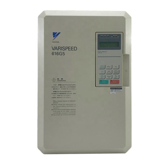
YASKAWA VARISPEED-616G5 Instruction Manual
200v class 0.4 to 75kw (1.2 to 110kva) 400v class 0.4 to 300kw (1.4 to 460kva)
Hide thumbs
Also See for VARISPEED-616G5:
- Instructions manual (12 pages) ,
- Instructions manual (11 pages) ,
- Instructions manual (9 pages)
Table of Contents
Advertisement
Quick Links
Advertisement
Table of Contents
Troubleshooting

Related Manuals for YASKAWA VARISPEED-616G5


Summary of Contents for YASKAWA VARISPEED-616G5
- Page 2 Preface Preface The VARISPEED-616G5 Series of general-purpose Inverters provides V/f control and vector con- trol as standard features along with user-friendly operation. This manual is designed to ensure correct and suitable application of VARISPEED-616G5-series Inverters. Read this manual before attempting to install, operate, maintain, or inspect an Inverter and keep it in a safe, convenient location for future reference.
- Page 3 The warning symbols for ISO and JIS standards are different, as shown below. The ISO symbol is used in this manual. Both of these symbols appear on warning labels on Yaskawa products. Please abide by these warning labels regard- less of which symbol is used.
- Page 4 Visual Aids Visual Aids The following aids are used to indicate certain types of information for easier reference. EXAMPLE " Indicates application examples. Indicates supplemental information. INFO IMPORTANT Indicates important information that should be memorized.
- Page 5 D When ordering a new copy of the manual due to damage or loss, contact your Yaskawa rep- resentatives or the nearest Yaskawa sales office and provide the manual number shown on the front cover.
- Page 6 How to Change the Digital Operator Display from Japanese to English Safety Precautions Confirmations upon Delivery CAUTION Page D Never install an Inverter that is damaged or missing components. 2 - 2 Doing so can result in injury. J Installation CAUTION Page D Always hold the case when carrying the Inverter.
- Page 7 CAUTION Page D Do not connect AC power to output terminals U, V, and W. 3 - 2 The interior parts of the Inverter will be damaged if voltage is applied to the output terminals. D Do not connect phase-advancing capacitors or LC/RC noise filters to the output cir- 3 - 2 cuits.
- Page 8 How to Change the Digital Operator Display from Japanese to English CAUTION D Don’t check signals while the Inverter is running. 5 - 2 Otherwise, the equipment may be damaged. D Be careful when changing Inverter settings. The Inverter is factory set to suitable set- 5 - 2 tings.
- Page 9 Warning Label Contents and Position There is a warning label on the Inverter in the position shown in the following illustration. Always heed the warn- ings given on this label. Warning label position Illustration shows the CIMR-G5A23P7 Warning Label Contents viii...
- Page 10 How to Change the Digital Operator Display from Japanese to English How to Change the Digital Operator Display from Japanese to English If the Digital Operator displays messages in Japanese, change to the English mode using the follow- ing steps. (This manual provides descriptions for the English mode.)
- Page 11 Version code SPEC : 20P41F MODEL : CIMR−G5A20P4 INPUT : AC 3PH 200-220 V 50Hz 200-230 V 60Hz OUTPUT : AC 3PH 0-230 V 1.2kVA 3.2 A LOT NO : MASS : 3.0kg SER NO : JAPAN YASKAWA ELECTRIC CORPORATION...
- Page 12 CONTENTS 11 Introduction 12 Handling Inverters 13 Wiring 14 Setting User Constants 15 Trial Operation 16 Basic Operation 17 Advanced Operation 18 User Constants 19 Troubleshooting 10 Maintenance and Inspection 11 Specifications 12 Appendix...
- Page 13 Table of Contents Table of Contents Introduction ........1 - 1 1.1 Outline and Functions .
- Page 14 Setting User Constants ......4 - 1 4.1 Using the Digital Operator .
- Page 15 Table of Contents Advanced Operation ....... . 7 - 1 7.1 Open-loop Vector Control .
- Page 16 9.2 Troubleshooting ..........9 - 9 9.2.1 If Constant Constants Cannot Be Set .
- Page 17 Introduction This chapter provides an overview of the VS-616G5 Inverter and describes its functions and components. 1.1 Outline and Functions ....1 - 2 1.1.1 VS-616G5 Inverter Models .
- Page 18 Introduction 1.1.1 VS-616G5 Inverter Models 1.1 Outline and Functions The VS-616G5 Inverters provides full-current vector control based on advanced control logic. An autotuning function is included for easy vector control. The Digital Operator provides a liquid crystal display that is 2 lines by 16 characters in size. User constant set- tings and monitor items are easily read in interactive operations in either Japanese or English.
- Page 19 1.1 Outline and Functions Inverter Specifications VS-616G5 (Specify all required standards when ordering.) Maximum Maximum Voltage Voltage Applicable Applicable Enclosed Wall-mounted Open Chassis Type Class Class Motor Out- Motor Out- Output Ca- Type Model Number (IEC IP 00) put [kW] put [kW] pacity [kVA] (IEC IP 20, NEMA 1)
- Page 20 Introduction 1.1.2 Outline of Control Methods 1.1.2 Outline of Control Methods The VS-616G5 uses four control methods. Open-loop vector control (factory setting) Flux vector control V/f control without PG V/f control with PG feedback PG stands for pulse generator (encoder). Vector control is a method for removing interference with magnetic flux and torque, and controlling torque according to references.
- Page 21 1.1 Outline and Functions Current input within a range from 4 to 20 mA Input from Option Card Any of the above frequency references can be used by setting a constant. A maximum of nine frequency references can be registered with the Inverter. With remote multi-step speed reference inputs, the Inverter can operate in multi-step speed operation with a maximum of nine speed steps.
- Page 22 Introduction 1.1.3 Functions User Constant Structure and Three Access Levels The VS-616G5 has a number of user constants for setting various functions. These user constants are clas- sified into a hierarchy to make them easier to use. The levels are as follows from top to bottom: Modes, Groups, Functions, and Constants. The access levels for the user constants are shown in Table 1.3.
- Page 23 1.2 Nomenclature 1.2 Nomenclature This section provides the names of VS-616G5 components, and the components and functions of the Digital Operator. 1.2.1 VS-616G5 Components The appearance of Inverter and the names of its components are shown in Figure 1.2. Protective cover (top) Mounting hole Front cover Digital Operator...
- Page 24 Introduction 1.2.2 Digital Operator Components 1.2.2 Digital Operator Components This section describes the component names and functions of the Digital Operator. The component names and functions are shown in Figure 1.4 and key functions are described in Table 1.4. DRIVE FWD REV REMOTE Operation Mode Indicators DRIVE: Lit when in operation mode.
- Page 25 1.2 Nomenclature Table 1.4 Key Functions Name Function Switches between (LOCAL) operation via the Digital Operator and control circuit terminal (REMOTE) operation. LOCAL LOCAL/REMOTE Key REMOTE This key can be enabled or disabled by setting a user constant (o2-01). MENU Key Displays menus.
- Page 26 Handling Inverters This chapter describes the checks required upon receiving a VS-616G5 In- verter and describes installation methods. 2.1 Confirmations upon Delivery ... . 2 - 2 2.1.1 Nameplate Information .
- Page 27 Use a screwdriver or other tools to check for tightness. loose? If you find any irregularities in the above items, contact the agency from which you purchased the Inverter or your Yaskawa representative immediately. 2.1.1 Nameplate Information Example Nameplate Standard domestic (Japan) Inverter: 3-phase, 200 VAC, 0.4 kW, IEC IP20 and NEMA 1 standards...
- Page 28 2.1 Confirmations upon Delivery Inverter Specifications 2 0P4 1 F Voltage Class Version (Enter the specifications AC input, 3-phase, 200 V form number when special spec- ifications are required.) AC input, 3-phase, 400 V DC input, 3-phase, 200 V DC input, 3-phase, 400 V Max.
- Page 29 Handling Inverters 2.2 Exterior and Mounting Dimensions 200 V/400 V Class Inverters of 15 kW and Lower The following diagram shows a 200 V class, 1.5 kW Inverter. Remove the top and bottom covers when mounting 200 V/400 V class Inverters of 15 kW or lower in a control panel.
- Page 30 Note An attachment is required to mount the cooling fins (fin section) on the outside of the control panel for 200 V/400 V class Inverters of 15 kW or less. Please contact your Yaskawa representative for details. Dimensional drawings for models with externally mounted cooling fins and other special requirements are also available from your Yaskawa representative.
- Page 31 Handling Inverters 2.3.1 Installation Site 2.3 Checking and Controlling the Installation Site CAUTION D Always hold the case when carrying the Inverter. If the Inverter is held by the front cover, the main body of the Inverter may fall, possibly resulting in injury. D Attach the Inverter to a metal or other noncombustible material.
- Page 32 2.4 Installation Orientation and Space 2.4 Installation Orientation and Space Install the Inverter on a vertical surface so as not to reduce the cooling effect. When installing the Inverter, al- ways provide the following installation space to allow normal heat dissipation. 50 mm min.
- Page 33 Handling Inverters 2.5.1 Inverters of 15 kW or Less 2.5 Removing/Attaching the Digital Operator and Front Cover Remove the front cover to wire the terminals. For models of 15 kW or less (both 200 V and 400 V class), do not remove or mount the front cover without first removing the Digital Operator;...
- Page 34 2.5 Removing/Attaching the Digital Operator and Front Cover Mounting the Digital Operator Hook the Digital Operator at A (two locations) on the front cover in the direction of arrow 1 as shown in the following illustration. Press the Digital Operator in the direction of arrow 2 until it snaps in place at B (two locations). Digital Operator Front cover...
- Page 35 Wiring This chapter describes wiring terminals, main circuit terminal connections, main circuit terminal wiring specifications, control circuit terminals, and control circuit wiring specifications. 3.1 Connections to Peripheral Devices ..3 - 3 3.2 Connection Diagram .
- Page 36 Wiring WARNING D Always turn OFF the input power supply before wiring terminals. Otherwise, an electric shock or fire can occur. D Wiring must be performed by an authorized person qualified in electrical work. Otherwise, an electric shock or fire can occur. D Be sure to ground the ground terminal.
- Page 37 3.1 Connections to Peripheral Devices 3.1 Connections to Peripheral Devices Examples of connections between the VS-616G5 and typical peripheral devices are shown in Figure 3.1. Use this illustration to gain an understanding of the overall equipment configuration. Power supply Molded-case circuit breaker or ground fault interrupter Magnetic con-...
- Page 38 Wiring 3.2 Connection Diagram The connection diagram of the VS-616G5 is shown in Figure 3.2. When using the Digital Operator, the motor can be operated by wiring only the main circuits. DC reactor to improve input Braking Resistor Unit (Optional) power factor (optional) Short-circuit bar ¨...
- Page 39 3.3 Terminal Block Configuration IMPORTANT 1. Control circuit terminals 1 to 33 are not arranged in order of terminal numbers; they are arranged as shown below. Be sure to wire them correctly. 12(G) 2. Do not use control circuit terminals 13 and 14 at the same time. (The two signals will be added inside the Inverter if they are input at the same time.) 3.
- Page 40 Wiring 3.4.1 Applicable Wire Sizes and Closed-loop Connectors 3.4 Wiring Main Circuit Terminals 3.4.1 Applicable Wire Sizes and Closed-loop Connectors Select the appropriate wires and crimp terminals from Table 3.1 to Table 3.3. Refer to instruction manual TOE-C726-2j for wire sizes for Braking Resistor Units and Braking Units. Table 3.1 200 V Class Wire Sizes Wire Thickness...
- Page 41 3.4 Wiring Main Circuit Terminals Termi- Wire Thickness VS-616G5 Model Circuit Terminal Symbol Wire Type (see note) CIMR- Screws R, S, T, © , ¨ 1 , ¨ 2, B1, B2, U, V, W G5A40P4 G5A40P4 2 to 5 5 2 to 5.5 R, S, T, ©...
- Page 42 Wiring 3.4.1 Applicable Wire Sizes and Closed-loop Connectors Table 3.3 Closed-loop Connector Sizes (JIS C 2805) (For 200 V/400 V Classes) Wire Thickness mm Terminal Screws Size M3.5 1.25 to 3.5 1.25 to 4 M3.5 1.25 to 3.5 0 75 0.75 1.25 to 4 M3.5...
- Page 43 3.4 Wiring Main Circuit Terminals 3.4.2 Main Circuit Terminal Functions Main circuit terminal functions are summarized according to terminal symbols in Table 3.4 and Table 3.5. Wire the terminals correctly for the desired purposes. Table 3.4 200 V Class Main Circuit Terminal Functions Purpose Terminal Symbol Model: CIMR-G5A...
- Page 44 Wiring 3.4.3 Main Circuit Configurations 3.4.3 Main Circuit Configurations The main circuit configurations are shown in Figure 3.4 and Figure 3.5. 200 V Class CIMR-G5A20P4 to 21P5 (0.4 to 1.5 kW) CIMR-G5A22P2 to 27P5 (2.2 to 7.5 kW) ¨1 ¨1 ¨2 ¨2 (DCL...
- Page 45 3.4 Wiring Main Circuit Terminals 400 V Class CIMR-G5A40P4 to 41P5 (0.4 to 1.5 kW) CIMR-G5A42P2 to 43P7 (2.2 to 3.7 kW) ¨1 ¨1 ¨2 ¨2 (DCL (DCL U(T1) U(T1) R(L1) R(L1) option) option) S(L2) V(T2) V(T2) S(L2) T(L3) W(T3) T(L3) W(T3) ©...
- Page 46 Wiring 3.4.4 Standard Connection Diagrams 3.4.4 Standard Connection Diagrams CIMR-G5A20P4 to 27P5, 40P4 to 4015 CIMR-G5A2011, 2015 Braking Resistor Unit (optional) DC reactor DC reactor Braking Resistor Braking Unit (optional) (optional) Unit (optional) (optional) © ¨1 ¨2 B1 ¨1 ¨2 ¨3 ©...
- Page 47 3.4 Wiring Main Circuit Terminals 3.4.5 Wiring the Main Circuits This section describes wiring connections for the main circuit inputs and outputs. Wiring Main Circuit Inputs Installing a Molded-case Circuit Breaker Always connect the power input terminals (R, S, and T) and power supply via a molded-case circuit break- er (MCCB) suitable for the Inverter.
- Page 48 Wiring 3.4.5 Wiring the Main Circuits Installing an AC Reactor If the Inverter is connected to a large-capacity power transformer (600 kW or more) or the phase advancing capacitor is switched, an excessive peak current may flow through the input power circuit, causing the con- verter unit to break down.
- Page 49 3.4 Wiring Main Circuit Terminals Wiring on the Output Side of Main Circuit Connecting the Inverter and Motor Connect output terminals U, V, and W to motor lead wires U, V, and W, respectively. Check that the motor rotates forward with the forward run command. Switch over any two of the output terminals to each other and reconnect if the motor rotates in reverse with the forward run command.
- Page 50 Wiring 3.4.5 Wiring the Main Circuits Countermeasures Against Radio Interference Radio noise is generated from the Inverter as well as from the input and output lines. To reduce radio noise, install noise filters on both input and output sides, and also install the Inverter in a totally enclosed steel box.
- Page 51 3.4 Wiring Main Circuit Terminals Connecting the Braking Resistor (ERF) Connect the braking resistor as shown in Figure 3.14. L8-01 (Overheat protection of braking 1 (Enables overheat protection) resistor) 0 (Disables stall prevention function) L3-04 (Stall prevention during decelera- tion) tion) 3 (Enables stall prevention function with braking (Select either one of them.)
- Page 52 Wiring 3.4.5 Wiring the Main Circuits 200 V Class Inverters with 11 kW or higher Output and 400 V Class Inverters with 18.5 or higher Output LKEB Braking Re- CDBR Braking sistor Unit Unit ¨3 ¨ ¨ Thermal protector VS-616G5 trip contact ©...
- Page 53 3.4 Wiring Main Circuit Terminals Connecting Braking Units in Parallel When connecting two or more Braking Units in parallel, use the wiring and connectors shown in Figure 3.16. There are connectors for selecting whether each Braking Unit is to be a Master or Slave. Select “Mas- ter”...
- Page 54 Wiring 3.5.1 Wire Sizes and Closed-loop Connectors 3.5 Wiring Control Circuit Terminals A control signal line must not be longer than 50 m and must be separated from power lines. The frequency reference must be input to the Inverter through twisted-pair wires. 3.5.1 Wire Sizes and Closed-loop Connectors Terminal numbers and wire sizes are shown in Table 3.7.
- Page 55 3.5 Wiring Control Circuit Terminals 3.5.2 Control Circuit Terminal Functions The functions of the control circuit terminals are shown in Table 3.9. Use the appropriate terminals for the correct purposes. Table 3.9 Control Circuit Terminals Type Signal Name Function Signal Level Forward run/stop command Forward run when CLOSED;...
- Page 56 Wiring 3.5.3 Control Circuit Terminal Connections (All Models) 12(G) Fig 3.19 Control Circuit Terminal Arrangement 3.5.3 Control Circuit Terminal Connections (All Models) Connections to VS-616G5 control circuit terminals are shown in Figure 3.20. Forward run/stop Fault output (NO) Reverse run/stop Fault output (NC) Multi-function contact input 1 Fault output common...
- Page 57 3.6 Wiring Check 3.5.4 Control Circuit Wiring Precautions Separate control circuit wiring (terminals 1 to 33) from main circuit wiring (terminals R, S, T, B1, B2, U, V, W, ©, ¨1, ¨2, and ¨3) and other high-power lines. Separate wiring for control circuit terminals 9, 10, 18, 19, and 20 (contact outputs) from wiring for terminals 1 to 8, 21, 22, 23, 25, 26, 27, 33 and 11 to 17.
- Page 58 Wiring 3.7.1 Installing a PG Speed Control Card 3.7 Installing and Wiring PG Speed Control Cards PG Speed Control Cards are used for executing speed control using a pulse generator (PG). There are four types of PG speed control, as shown below. Select the type that fits the application and control method. PG-A2 A-phase (single) pulse input for open collector output or complementary outputs, for V/f control PG-B2...
- Page 59 3.7 Installing and Wiring PG Speed Control Cards 3.7.2 PG Speed Control Card Terminal Blocks The terminal specifications for each PG Speed Control Card are given in the following tables. PG-A2 (For V/f with PG Feedback Mode Only) Table 3.10 PG-A2 Terminal Specifications Terminal Contents...
- Page 60 Wiring 3.7.2 PG Speed Control Card Terminal Blocks PG-X2 (For Flux Vector Control Mode Only) Table 3.13 PG-X2 Terminal Specifications Terminal Contents Specifications 12 VDC (±5%), 200 mA max. (see note) 0 VDC (GND for power supply) Power supply for pulse generator pp y 5 VDC (±5%), 200 mA max.
- Page 61 3.7 Installing and Wiring PG Speed Control Cards 3.7.3 Wiring a PG Speed Control Card Wiring examples are provided in the following illustrations for the PG Speed Control Cards. PG-A2 (For V/f with PG Feedback Mode Only) 12 V Voltage Input VS-616G5 Three-phase, 200 VAC (400 VAC)
- Page 62 Wiring 3.7.3 Wiring a PG Speed Control Card I/O Circuit Configuration +12 V PG power supply +12 V Pulse input +12 V Short for +12 V open-col- lector input +12 V Pulse monitor output Pulse input 3.9 k Fig 3.25 I/O Circuit Configuration of the PG-A2 3 - 28...
- Page 63 3.7 Installing and Wiring PG Speed Control Cards PG-B2 (For Flux Vector Control Mode Only) VS-616G5 Three-phase 200 VAC (400 VAC) PG-B2 Power supply +12 V Power supply 0 V A-phase pulse output (+) A-phase pulse output (−) B-phase pulse output (+) B-phase pulse output (−) A-phase pulse monitor output B-phase pulse monitor output...
- Page 64 Wiring 3.7.3 Wiring a PG Speed Control Card PG-D2 (For V/f with PG Feedback Mode Only) VS-616G5 Three-phase 200 VAC (400 VAC) PG-D2 Power supply +12 V Power supply 0 V Power supply +5 V Pulse input + (A/B phase) Pulse input −...
- Page 65 3.7 Installing and Wiring PG Speed Control Cards 3.7.4 Wiring PG Speed Control Card Terminal Blocks Use no more than 100 meters of wiring for PG (encoder) signal lines, and keep them separate from power lines. Use shielded, twisted-pair wires for pulse inputs and pulse output monitor wires, and connect the shield to the shield connection terminal.
- Page 66 Wiring 3.7.4 Wiring PG Speed Control Card Terminal Blocks Closed-loop Connector Sizes and Tightening Torque The closed-loop connectors and tightening torques for various wire sizes are shown in Table 3.16. Table 3.16 Closed-loop Connectors and Tightening Torques Terminal Wire Thickness [mm Crimp Terminal Size Tightening Torque (N G m) Screws...
- Page 67 3.7 Installing and Wiring PG Speed Control Cards 3.7.5 Selecting the Number of PG (Encoder) Pulses PG-A2/PG-B2 The maximum response frequency is 32,767 Hz. Use a PG that outputs a maximum frequency of approximately 20 kHz for the rotational speed of the motor. r∕min Motor speed at maximum frequency output ( p∕rev...
- Page 68 Setting User Constants This chapter describes setting user constants using the Digital Operator. 4.1 Using the Digital Operator ....4 - 2 4.2 Modes ....... 4 - 4 4.2.1 Inverter Modes .
- Page 69 Setting User Constants 4.1 Using the Digital Operator This section describes the component names and functions of the Digital Operator. The component names and functions are shown in Figure 4.1 and Key functions are described in Table 4.1. DRIVE FWD REV REMOTE Operation Mode Indicators DRIVE: Lit when in operation mode.
- Page 70 4.1 Using the Digital Operator Table Key Functions Name Function Switches between operation (LOCAL) via the Digital Operator and control circuit terminal (REMOTE) operation. LOCAL LOCAL/REMOTE Key REMOTE This Key can be enabled or disabled by setting a user constant (o2-01).
- Page 71 Setting User Constants 4.2.1 Inverter Modes 4.2 Modes This section describes the VS-616G5’s monitor modes, switching between modes, and accessing/setting user constants. 4.2.1 Inverter Modes The VS-616G5 Inverter’s user constants and monitoring functions have been organized in groups called modes that make it easier to read and set user constants. The VS-616G5 is equipped with 5 modes, as shown in the Table 4.2.
- Page 72 4.2 Modes 4.2.2 Switching Modes Once the Inverter has been put into operation mode by pressing the Menu Key, the Increment and Decre- ment Keys can be pressed to switch to other modes. Press the DATA/ENTER Key to read/set the user constants in each mode.
- Page 73 Setting User Constants 4.2.3 User Constant Access Levels 4.2.3 User Constant Access Levels The VS-616G5 has three access levels which divide the various user constants based on their applications, as shown below. The access level restricts which user constants can be set or displayed. Quick-start Allows reading/setting of user constants required for simple operation.
- Page 74 4.2 Modes Setting User Constants in Each Access Level The displayed access level will change when programming mode is selected. The display will not change for access levels in operation mode, initialize mode, autotuning mode, and modified constants mode. This section provides the procedure to change the acceleration time to 20.0 s in each access level. The ac- celeration time (C1-01) is a user constant in programming mode.
- Page 75 Setting User Constants 4.2.3 User Constant Access Levels EXAMPLE Setting a User Constant in the Quick-start Access Level " The user constant level will be displayed when the DATA/ENTER Key is pressed at the programming mode display. Use the following display to set the acceleration time to 20.0 s. Step Key Sequence Digital Operator Display...
- Page 76 4.2 Modes EXAMPLE Setting a User Constant in the Basic Access Level " The function level will be displayed when the DATA/ENTER Key is pressed at the programming mode display. Use the following display to set the acceleration time to 20.0 s. Step Key Sequence Digital Operator Display...
- Page 77 Setting User Constants 4.2.3 User Constant Access Levels EXAMPLE Setting a User Constant in the Advanced Access Level " The group level will be displayed when the DATA/ENTER Key is pressed at the programming mode dis- play. Use the following procedure to set a constant. Step Key Sequence Digital Operator Display...
- Page 78 4.2 Modes 4.2.4 Operation Mode Operation mode is the mode in which the Inverter can be operated. Many user constants can’t be changed when the Inverter is operating. Refer to User Constant List for de- tails. The following monitor displays are possible in operation mode: The frequency reference, output frequen- cy, output current, and output voltage, as well as fault information and the fault history.
- Page 79 Setting User Constants 4.2.4 Operation Mode Conditions for Monitoring Table 4.3 shows the items that can be monitored in operation mode. The “Valid access levels” column in the table indicates whether an item can be monitored in a particular access level and control method. The codes in this column have the following meanings. Items that can be monitored in all access levels.
- Page 80 4.2 Modes Name Valid Access Levels Con- Con- Output Signal Levels for Output Signal Levels for Func- Func- Min. Min. Open stant stant Function Function Multi-function Analog Out- Multi-function Analog Out- Flux Digital Operator tion tion Unit Unit V/f w/ -loop Vec- puts...
- Page 81 Setting User Constants 4.2.4 Operation Mode Name Valid Access Levels Con- Con- Output Signal Levels for Output Signal Levels for Func- Func- Min. Min. Open stant stant Function Function Multi-function Analog Out- Multi-function Analog Out- Flux Digital Operator tion tion Unit Unit V/f w/...
- Page 82 4.2 Modes Table 4.3 Constants Monitored in Operation Mode (Continued) Name Valid Access Levels Const Const Output Signal Levels for Output Signal Levels for Func- Min. Open Function Multi-function Analog Out- Flux Digital Operator tion Units V/f w/ -loop Vec- puts Display Vec-...
- Page 83 Setting User Constants 4.2.4 Operation Mode Name Valid Access Levels Const Const Output Signal Levels for Output Signal Levels for Func- Min. Open Function Multi-function Analog Out- Flux Digital Operator tion Units V/f w/ -loop Vec- puts Display Vec- Most recent fault U3 01 U3-01 Information on the last fault...
- Page 84 4.2 Modes Indicates the control methods and access levels under which the constant can be accessed and set. Accessible/settable under all access levels (Quick-start, Basic, and Advanced). Valid Access Valid Access Accessible/settable under Advanced or Basic access levels. Levels Accessible/settable under Advanced access level. Not accessible/settable in the specified control method.
- Page 85 Setting User Constants 4.2.5 Initialize Mode EXAMPLE Changing Monitor Display to Output Current at Startup in Basic Access Level " Use the following procedure to change user constant o1-02 so that the output current is displayed at startup. (The procedure continues from the end of the previous example.) Step Key Sequence Digital Operator Display...
- Page 86 4.2 Modes Selecting the Display Language: A1-00 Use constant A1-00 to select the language displayed by the Inverter. A value of 0 sets English and a value of 1 sets Japanese. This user constant is not returned to the factory setting when constants are initialized. It must be manu- ally reset to the factory setting.
- Page 87 Setting User Constants 4.2.5 Initialize Mode Access Level Settings Setting Function This setting allows the operation mode and initialize mode to be changed or displayed. Operation Only Use this setting to prevent user constant settings from being changed. This setting allows only the user-selected constants (up to 32) to be changed or displayed.
- Page 88 4.2 Modes Table Control Method Characteristics Characteristic V/f Control without PG V/f Control with PG Open Loop Vector Control Flux Vector Control Basic Control Voltage/frequency control Voltage/frequency control Current vector control Current vector control with Method (open loop) with speed compensation without PG Speed Detector Not required...
- Page 89 Setting User Constants 4.2.5 Initialize Mode When setting a 3-wire sequence, the operation can be started and stopped with an automatically reset- ting pushbutton switch. Stop switch (NC) Run switch (NO) Run command (Operates when the run switch is closed.) Stop command (Stops when the stop switch is open.) Forward/Reverse run command...
- Page 90 4.2 Modes Passwords: A1-04, A1-05 Use constants A1-04 and A1-05 to write-protect the initialize-mode user constants. User constants A1-01 through A1-03 and A2-01 through A2-32 can be displayed but not changed if the contents of A1-04 and A1-05 are not the same. To write-protect the initialize-mode user constants, set the password in A1-05 after inputting the de- sired values in A1-01 through A1-03 and A2-01 through A2-32.
- Page 91 Setting User Constants 4.2.5 Initialize Mode Programming Only the user constants specified in A2-01 through A2-32 can be displayed or set. Autotuning The user constants cannot be displayed. Modified constants The user constants cannot be displayed. EXAMPLE Setting C1-08 (Deceleration Time 4) in A2-01 to Define it as a User Constant "...
- Page 92 4.2 Modes Step Key Sequence Digital Operator Display Remarks After a few seconds, the Operator dis- Access Level play is as shown on the left. User Program G5: Main Menu : Initialize The access level has been set to the user program access level. Figure 4.10 shows the structure of the user constants.
- Page 93 Setting User Constants 4.2.6 Programming Mode Table Programming Mode Constant Groups Control Meth- Group Function Display Comments Settings such as the reference input Operating modes Sequence f f f f method DC braking DC Braking DC braking function settings f f f f Speed searching Speed Search Speed search function settings...
- Page 94 4.2 Modes Control Meth- Group Function Display Comments PG speed control card PG Option Setup User constant settings for a PG Card × f × settings Analog Reference Card User constant settings for an Analog AI-14 Setup f f f f Reference Card User constant settings for a Digital Ref- Digital Reference Card DI DI-08, 16 Setup...
- Page 95 Setting User Constants 4.2.6 Programming Mode Figure 4.11 shows the difference in the display structure for the various access levels. Advanced Level Basic Level Quick-start Level DATA DATA [Mode] [Group] [Function] [Constant] ENTER ENTER Operation mode b1 Sequence b1-01 Reference selection b Application MENU b1-02 Operation method selection...
- Page 96 E1-04 through E2-09 automatically. When the motor cannot be disconnected from the load, motor constants can be set by calculation. Contact your Yaskawa representatives for details. The autotuning mode won’t be displayed if V/f control has been selected. Refer to Setting the Control Method: A1-02 under 4.2.5 Initialize Mode.
- Page 97 Setting User Constants 4.2.7 Autotuning Mode Step Key Sequence Digital Operator Display Remarks Number of Poles Press the keys as in steps 4, 5, 6 of DATA DATA ENTER ENTER RESET rated voltage setting. Select Motor 1/2 Press the keys as in steps 4, 5, 6 of DATA DATA ENTER...
- Page 98 4.2 Modes 4.2.8 Modified Constants Mode The modified constants mode is used to change or display user constants that have been changed from their factory-preset values. When any user constants have been changed in programming mode (b1-01 through o2-08), press the DATA/ENTER Key in modified constants mode to display these user constants.
- Page 99 Trial Operation This chapter describes the preparations and Digital Operator procedures for trial operation of the VS-616G5 and provides an example of trial operation. 5.1 Procedure ......5 - 3 5.2 Trial Operation Procedures .
- Page 100 Trial Operation 5.2.5 Autotuning WARNING D Check to be sure that the front cover is attached before turning ON the power supply. Do not remove the front cover during operation. An electric shock may occur. D Do not come close to the machine when the fault reset function is used. If the alarmed is cleared, the machine may start moving suddenly.
- Page 101 S Check the Inverter capacity setting (kVA) in o2-04 before replacing the controller PCB with a spare. * 2 When the motor cannot be disconnected from the load, motor constants can be set by calculation. Contact your Yaskawa representatives for details. 5 - 3...
- Page 102 Trial Operation 5.2.5 Autotuning 5.2 Trial Operation Procedures 5.2.1 Power ON Checkpoints before Turning ON the Power Supply Check that the power supply is of the correct voltage. 200 V class: 3-phase 200 to 230 VDC, 50/60 Hz 400 V class: 3-phase 380 to 460 VDC, 50/60 Hz Make sure that the motor output terminals (U, V, W) and the motor are connected correctly.
- Page 103 5.2 Trial Operation Procedures 5.2.4 Setting Input Voltage Set the input voltage of the Inverter (E1-01) according to the power supply voltage. Input Voltage: E1-01 Set the input voltage. Change Valid Access Levels User User during during Setting Setting Unit Factory Factory Constant Name...
- Page 104 Trial Operation 5.2.5 Autotuning 4. Replace the front cover. 23CN 24CN 25CN 26CN 22CN FU2 21CN 380V 400/415V 440V 460V Jumper Fig 5.1 Setting the Power Supply Voltage (Illustration Above is for 400 V Class Inverter between 18.5 kW and 45 kW) Motor Selection (Motor Overheating Protection): E1-02 Set the type of motor being used with the motor selection constant (E1-02).
- Page 105 5.2 Trial Operation Procedures Step Key Sequence Digital Operator Display Remarks Indicates the completion of autotun- Tune Successful ing. Returns to the operation mode dis- G5: Main Menu : MENU play. Operation *1 When the values displayed and the motor constants differ, set each value seperately. *2 There are differences between simple and advanced settings.
- Page 106 Trial Operation 5.2.5 Autotuning Display Message Fault Description Countermeasure S Increase the acceleration time (C1-01). S Increase the torque limits (L7-01, -02) if The motor did not accelerate with- Accelerate Acceleration fault these have been decreased. in a set time. S Disconnect the motor from the machine if it has been connected.
- Page 107 5.2 Trial Operation Procedures 2. Check the motor nameplate and set the following three items. Change Valid Access Levels User User during during Setting Setting Unit Factory Factory Name Constant Open V/f with Flux Opera- Range Setting Loop Number Control Vector tion Vector...
- Page 108 Trial Operation 5.2.5 Autotuning Step Key Sequence Digital Operator Display Remarks The set values are overwritten. DATA ENTER Entry Accepted Returns to the frequency reference Frequency Ref display. 010. 00 HZ Operation Using the Digital Operator Press the RUN Key. The motor will start to rotate. (forward rotation) Press the FWD/REV Key.
- Page 109 Basic Operation This chapter explains the basic settings required to operate and stop the VS-616G5. The user constants described here will be sufficient for simple Inverter. Even when your application requires special functions, such as torque con- trol or PID control, make these basic settings first and then go to the explana- tions of those special functions in chapter 7 Advanced Operation.
- Page 110 Basic Operation 6.1.1 Setting the Access Level and Control Method: A1-01, A1-02 6.1 Common Settings This section describes the constants that are used with all of the control methods. 6.1.1 Setting the Access Level and Control Method: A1-01, A1-02 Constant Access Level: A1-01 Select the constant access level.
- Page 111 6.1 Common Settings Control Method: A1-02 Select one of the four control methods. This constant is not initialized by the initialize operation. Change Valid Access Levels User User during during Setting Setting Unit Factory Factory Constant Name Open V/f with Flux Opera- Range...
- Page 112 Basic Operation 6.1.2 Frequency Reference Settings: b1-01, H3-01, H3-08, H3-09 6.1.2 Frequency Reference Settings: b1-01, H3-01, H3-08, H3-09 These settings are required when inputting analog voltage or current signals from the control circuit termi- nals. Frequency Reference Selection: b1-01 Constant b1-01 is used to select the reference source. Change Valid Access Levels User...
- Page 113 6.1 Common Settings Change Valid Access Levels User User during during Setting Setting Unit Factory Factory Constant Name Open V/f with Flux Opera- Range Setting Loop Number Control Vector tion Vector Signal level selec- H3-08 0 to 2 − × tion (terminal 14) Settings Setting...
- Page 114 Basic Operation 6.1.2 Frequency Reference Settings: b1-01, H3-01, H3-08, H3-09 Function and Signal Level for Multi-function Analog Input (Terminal 16): H3-04, H3-05 This function is useful when switching between two analog inputs. The input is from terminal 16. When using the multi-function input (terminal 16) as the frequency reference terminal, first set the multi-function analog input function to “Auxiliary Reference”...
- Page 115 6.1 Common Settings Frequency reference Max. output frequency × Gain Max. output frequency × Bias Use the current values shown in parentheses when current input 10 V has been selected. (4 mA) (20 mA) Fig 6.2 Gain and Bias Chart Analog Input Filter Time Constant: H3-12 A primary delay digital filter can be set for all three analog inputs (frequency reference (voltage), fre- quency reference (current), and multi-function analog input)
- Page 116 Basic Operation 6.1.3 Frequency Reference from Digital Operator: b1-01, o1-03, d1-01 to d1-09 Setting Function r/min units 2 to 39 r/min = 120 × frequency reference (Hz)/o1-03 (o1-03 becomes the motor pole) Set the binary point position using the value of the fifth digit of o1-03. The display when the fifth digit = 0 will be VVVV The display when the fifth digit = 1 will be VVV.V The display when the fifth digit = 2 will be VV.VV...
- Page 117 6.1 Common Settings 6.1.4 Run Source and Sequence Input Responsiveness: b1-02, b1-06, b1-07 Run Source: b1-02 Change Valid Access Levels User User during during Setting Setting Unit Factory Factory Constant Name Open V/f with Flux Opera- Range Setting Loop Number Control Vector tion...
- Page 118 Basic Operation 6.1.5 Acceleration/Deceleration Times: C1-01 through C1-08, C1-09, C1-10, C1-11 6.1.5 Acceleration/Deceleration Times: C1-01 through C1-08, C1-09, C1-10, C1-11 This section describes setting the acceleration times, deceleration times, and emergency stop time. Acceleration/Deceleration Time Unit: C1-10 Change Valid Access Levels User User during...
- Page 119 6.1 Common Settings Change Valid Access Levels User User during during Setting Setting Unit Factory Factory Constant Name Open V/f with Flux Opera- Range Setting Loop Number Control Vector tion Vector 0.0 to C1-09 Emergency stop time 10.0 6000.0 The setting range for the emergency stop deceleration time depends upon the setting in C1-10 (accel- eration/deceleration time unit).
- Page 120 Basic Operation 6.1.7 Selecting the Stopping Method: b1-03 6.1.7 Selecting the Stopping Method: b1-03 Set the stopping method used when a stop command is input. Change Valid Access Levels User User during during Setting Setting Unit Factory Factory Name Constant Open V/f with Flux...
- Page 121 6.1 Common Settings IMPORTANT Lengthen the minimum baseblock time (L2-03) when an overcurrent (OC) occurs during stopping. When the power to an induction motor is turned OFF, the counter-electromotive force generated by the residual magnet- ic field in the motor can cause an overcurrent to be detected when DC injection braking is applied. Coast to Stop with Timer (b1-03 = 3) •...
- Page 122 Basic Operation 6.1.8 Multi-function Input Settings: H1-01 through H1-06 3-wire Sequence (Forward/Reverse Run Commands): “0” When a value of “0” is set for any one of the multi-function inputs (H1-01 through H1-06), 3-wire se- quence control is used and the multi-function input terminal for which “0” was set becomes the for- ward/reverse run command terminal.
- Page 123 6.1 Common Settings The following table shows which frequency is selected by each possible combination of multi-step speed and JOG reference settings. Terminal 5 Terminal 6 Terminal 7 Terminal 8 Selected frequency Multi-step speed Multi-step speed Multi-step speed JOG reference reference 1 reference 2 reference 3...
- Page 124 Basic Operation 6.1.8 Multi-function Input Settings: H1-01 through H1-06 Three-step Speed Operation Example The following example shows three-step speed operation with frequencies set at Inverter constants. Sequence d1-03 d1-02 d1-01 Output frequency CLOSED OPEN Forward/reverse run command, terminal 1 or 2 CLOSED OPEN Multi-step speed reference...
- Page 125 6.1 Common Settings Acceleration/Deceleration Time Selectors 1 and 2: “7” and “1A” Four acceleration times and four deceleration times can be set. The multi-function inputs can be set as acceleration/deceleration time selectors 1 and 2 to switch between these acceleration and decelera- tion times.
- Page 126 Doing so may result in personal injury or equipment damage. When the motor cannot be disconnected from the load, motor constants can be set by calculation. Contact your Yaskawa representatives for details. Precautions before Autotuning The Inverter’s autotuning function automatically determines the motor constants while a servo sys- tem’s autotuning function determines the size of a load, so these autotuning functions are fundamental-...
- Page 127 6.2 Open-loop Vector Control Rated Frequency* • Set the rated frequency (Hz) shown on the motor nameplate. Rated Speed • Set the rated speed (r/min) shown on the motor nameplate. Number of Poles • Set the number of poles. Motor Selection •...
- Page 128 Basic Operation 6.2.2 Autotuning Faults Table 6.2 Troubleshooting Autotuning Faults for Open-loop Vector Control Fault Display Probable Cause Remedy There was a fault in the rela- Change the settings to conform to the follow- Data Invalid There was a fault in the data tionship between the rated ing equation: set during autotuning.
- Page 129 6.3 V/f Control 6.3 V/f Control With V/f control, the user must set the Inverter input voltage, motor selection, rated current, and V/f pattern. 6.3.1 Setting the Motor Constants: E1-01, E1-02, E2-01 Inverter Input Voltage: E1-01 Set the Inverter input voltage (E1-01) to match the power supply voltage. Change Valid Access Levels User...
- Page 130 6.3.2 V/f Pattern Selection: E1-03 6.3.2 V/f Pattern Selection: E1-03 Change Valid Access Levels User User during during Setting Setting Unit Factory Factory Constant Name Open V/f with Flux Opera- Range Setting Loop Number Control Vector tion Vector E1-03 V/f pattern selection 0 to F −...
- Page 131 6.3 V/f Control V/f Patterns: 0.4 to 1.5 kW Fixed Torque Characteristics (Settings 0 to 3) Setting 0 50 Hz Setting 1 60 Hz Setting 2 60 Hz Setting 3 72 Hz 0 1.5 3 0 1.5 3 60 (Hz) 0 1.5 3 60 (Hz) 0 1.3 2.5...
- Page 132 6.3.2 V/f Pattern Selection: E1-03 V/f Patterns: 2.2 to 45 kW Fixed Torque Characteristics (Settings 0 to 3) Setting 0 50 Hz Setting 1 60 Hz Setting 2 60 Hz Setting 3 72 Hz 0 1.5 3 0 1.5 3 60 (Hz) 0 1.5 3 60 (Hz)
- Page 133 6.3 V/f Control V/f Patterns: 55 to 300 kW Fixed Torque Characteristics (Settings 0 to 3) Setting 0 50 Hz Setting 1 60 Hz Setting 2 60 Hz Setting 3 72 Hz 0 1.5 3 0 1.5 3 60 (Hz) 0 1.5 3 60 (Hz) 0 1.3 2.5...
- Page 134 6.3.2 V/f Pattern Selection: E1-03 Setting a User-defined V/f Pattern: E1-03 =“F” Constants E1-04 through E1-10 can be set by the user when E1-03 has been set to “F.” These constants are read-only when E1-03 isn’t set to “F.” When making the V/f characteristics a straight line, set the same value in E1-07 (middle output fre- quency) and E1-09 (minimum output frequency).
- Page 135 6.3 V/f Control Output voltage (V) VMAX (E1-05) VBASE (E1-13) (E1-08) VMIN (E1-10) Frequency (Hz) FMIN FMAX (E1-09) (E1-07) (E1-06) (E1-04) Fig 6.11 User-defined V/f Pattern 6 - 27...
- Page 136 PG Rotation Direction: F1-05 This constant is used to coordinate the PG’s rotation direction with the motor’s rotation direction. The setting for the standard applicable Yaskawa PG (made by SUMTAK) is an advanced phase A for forward rotation. Generally, phase A leads when the PG rotates in the clockwise direction (looking from the input axis).
- Page 137 [Setting: 0] [Setting: 1] Phase A Phase A Phase B Phase B Forward rotation in a typical motor (applicable Yaskawa PG: made by Thermtac): The motor output shaft rotates in the counterclockwise direction with a forward inverter reference. Forward Forward rotation...
- Page 138 Basic Operation 6.4.1 PG Speed Control Card Settings Settings Setting Function Deceleration to stop using deceleration time 1 (C1-02). Coast to stop Emergency stop using the emergency-stop time (C1-09). Continue operation (To protect the motor and machinery, this is not normally set.) Overspeed Settings: F1-03, F1-8, F1-09 Overspeed refers to an excessive motor speed.
- Page 139 6.4 Flux Vector Control Setting Function Emergency stop using the emergency−stop time (C1−09)*2 Continue Operation (Displays ”DEV” and continues control )*2 * 1. Speed agreement conditions: The frequency reference and output frequency were entered in the speed agree detection width set in L4−02. * 2.
- Page 140 Basic Operation 6.4.2 Setting the Zero-speed Operation Constants Initial Excitation Settings: b2-01, b2-03, b2-04 Set the zero speed level, DC injection braking time at startup, and the DC injection braking time when stopping. Change Valid Access Levels User User during during Setting Setting...
- Page 141 The motor shaft will rotate when autotuning is performed. Confirm safety before starting autotuning. When the motor cannot be disconnected from the load, motor constants can be set by calculation. Con- tact your Yaskawa representatives for details. Inverter Input Voltage Setting: E1-01 Set the Inverter input voltage to match the power supply voltage.
- Page 142 Basic Operation 6.4.3 Autotuning PG Pulses/Rev: • Set the number of A-phase or B-phase pulses per revolution. 2. The following message will appear when the constants have been set: Tuning Ready? The “Press RUN Key” message will blink. Press RUN key 3.
- Page 143 6.4 Flux Vector Control Performing Autotuning Autotuning will start if the Run Key is pressed when the “Tuning Ready?” message is being displayed. The motor will operate during autotuning, so be sure that it is safe for the motor to operate before press- ing the Run Key.
- Page 144 Basic Operation 6.4.4 Speed Control (ASR) Structure Fault Display Probable Cause Remedy S The cable to the PG is bro- Pulses aren’t being input PG Circuit Fault ken/disconnected. from the PG even though a Check the wiring and correct any problems. rotation output is being sent PGO: PG break detected) S The PG’s power supply is...
- Page 145 6.4 Flux Vector Control Figure 6.15 shows how the proportional gain and integral time approach the ASR proportional gain 2 and ASR integral time 2 linearly. P, I P= C5-01 I = C5-02 P= C5-03 I = C5-04 (Low speed) Motor speed (Hz) C5-07 If C5-07 is set to 0.0, ASR proportional gain 1 and ASR integral...
- Page 146 Basic Operation 6.4.5 Speed Control (ASR) Gain 6.4.5 Speed Control (ASR) Gain Gain Adjustment Procedure Use the following procedure to adjust the gain with the mechanical system and actual load connected. At zero-speed, increase C5-01 (ASR P Gain 1) until there is no oscillation. At zero-speed, decrease C5-02 (ASR I Time 1) until there is no oscillation.
- Page 147 6.4 Flux Vector Control Adjusting ASR Proportional Gain 1 (C5-01) This gain setting adjusts the responsiveness of the speed control (ASR). The responsiveness is increased when this setting is increased. Usually this setting is higher for larger loads. Oscillation will occur if this setting is increased too much. The following diagram shows the type of changes that can occur in the response when the ASR propor- tional gain is changed.
- Page 148 Basic Operation 6.5.1 Motor Constants: E1-01, E1-02, E2-01, E2-04 6.5 V/f Control with PG With V/f control with a PG, the user must set the motor constants, V/f pattern, and PG Control Card settings, and then adjust the speed control gain. 6.5.1 Motor Constants: E1-01, E1-02, E2-01, E2-04 Inverter Input Voltage Setting: E1-01 Set the Inverter’s input voltage to match the power supply voltage.
- Page 149 6.5 V/f Control with PG 6.5.2 V/f Pattern Selection: E1-03 The V/f pattern can be set to any of the following: One of 15 preset patterns (settings 0 through E) • A custom user-set pattern (setting F) • The factory setting for E1-03 is “F” (user-defined V/f pattern), but the default contents of this setting are the same as setting “1.”...
- Page 150 Basic Operation 6.5.3 PG Speed Control Card Settings 6.5.3 PG Speed Control Card Settings Available PG Speed Control Cards There are 4 models of PG Speed Control Cards, but only 2 models can be used with vector control. PG-A2: Phase-A/Phase-B pulse inputs, complementary output •...
- Page 151 6.5 V/f Control with PG Change Valid Access Levels User User during during Setting Setting Unit Factory Factory Constant Name Open V/f with Flux Opera- Range Setting Loop Number Control Vector tion Vector Operation selection F1-02 0 to 3 − ×...
- Page 152 Basic Operation 6.5.4 Speed Control (ASR) Structure Settings Setting Function Deceleration to stop using deceleration time 1 (C1-02). Coast to stop Emergency stop using the emergency-stop time (C1-09). Continue operation (Display “DEV” and continue control.) Deceleration t to stop using deceler action time 1 ( c1−02)*2 Coast to stop *2 Emergency stop using the emergency−stop time (c1−09)*2 Continue Operation (Displays ”DEV”...
- Page 153 6.5 V/f Control with PG Figure 6.22 shows how the proportional gain and integral time are calculated from constants C5-01 through C5-04. P= C5-01 P, I I = C5-02 P= C5-03 I = C5-04 (Min. output frequency) Motor speed (Hz) E1-04 (Max.
- Page 154 Basic Operation 6.5.5 Adjusting Speed Control (ASR) Gain The multi-function analog outputs have the following functions with these constant settings. Multi-function analog output 1 (terminal 21): Outputs Inverter’s output frequency(0 to ±10 V). • Multi-function analog output 2 (terminal 23): Outputs the actual motor speed (0 to ±10 V). •...
- Page 155 Advanced Operation This chapter describes the user constants used for specific control methods in VS-616G5 application. 7.1 Open-loop Vector Control ....7 - 2 7.1.1 Torque Limit Function .
- Page 156 Advanced Operation 7.1 Open-loop Vector Control The functions that can be used with open-loop vector control are listed in Table 7.1. Details on functions that are specific to open-loop vector control (i.e. those marked with a L) are provided in the following table. Table 7.1 Open-loop Vector Control Functions Control Meth-...
- Page 157 7.1 Open-loop Vector Control Control Meth- Group Group Function Function Comments Comments Motor Protection Functions Sets thermal functions that protect the motor. Power Loss Ridethru Selects the power-loss processing method. Stall Prevention Accel/Decel stall prevention settings and selection Reference Detection Frequency detection settings and selection L Protection L Protection...
- Page 158 Advanced Operation 7.1.1 Torque Limit Function 7.1.1 Torque Limit Function With open-loop vector control, torque limits can be applied at an arbitrary value because the torque output by the motor is calculated internally. The torque limit function is useful when the load cannot sustain a torque above a certain level or to maintain the regenerative torque above a certain level.
- Page 159 7.1 Open-loop Vector Control Settings Setting Name Forward Torque Limit Reverse Torque Limit Regenerative Torque Limit Forward/Reverse Torque Limit The above table shows only those settings related to the torque limit function. Set the analog input terminal’s signal level, gain, and bias to match the actual input signal. The factory settings for the input terminal’s signal level are as follows: Terminal 16: 0 to 10 V (A 10 V input limits the torque to 100% of the motor’s rated torque.)
- Page 160 Advanced Operation 7.1.3 Setting/Adjusting Motor Constants 7.1.3 Setting/Adjusting Motor Constants Adjusting the V/f Pattern: E1-04 through E1-10, E1-13 Normally it isn’t necessary to adjust the V/f pattern with open-loop vector control. Adjust the V/f pattern when you want to change the maximum output frequency setting or decrease the Inverter’s output voltage or when stalls are occurring during no-load operation.
- Page 161 7.1 Open-loop Vector Control Adjusting Output Voltage: VC (E1-08), VMIN (E1-10) Adjust the output voltage when you want to output more torque at low speed, such as in an elevator, or when torque isn’t really necessary and you want to reduce the output voltage to save energy. Adjustment range: 200 V class Inverters: Initial value 0 to 2 V...
- Page 162 Advanced Operation 7.1.4 Operation Selection when Output Voltage Saturated The default setting depends upon the Inverter capacity. (The table shows the default settings for 200 V class, 0.4 kW Inverters.) Set the motor terminal resistance (U−V, V−W, and W−U) in constant E2-05. Normally this value isn’t shown on the motor nameplate, so it might be necessary to contact the motor manufacturer for the ter- minal resistance at the insulation class temperature.
- Page 163 7.1 Open-loop Vector Control If the limited output voltage operation is disabled and output voltage becomes saturated, slip com- pensation is automatically disabled to prevent instability. The output current does not change when the slip compensation is disabled, however precise speed control is no longer possible.
- Page 164 Advanced Operation 7.1.5 Starting Torque Compensation Function (for SPEC:F) Set the constant for starting torque compensation (C4-05) to a large value if a shock is generated during startup. Alternatively, use DC injection braking (b2-03) at startup or the DC braking command for multifunc- tion contact input (setting: 60), and start motor magnetic flux before startup.
- Page 165 7.2 V/f Control without PG 7.2 V/f Control without PG The functions that can be used with vector control without PG are listed in Table 7.2. Details on functions that are specific to vector control without PG (i.e. those marked with a ) are provided in the following table.
- Page 166 Advanced Operation Control Meth- Group Group Function Function Comments Comments Motor Overload Sets electrical/thermal functions that protect the motor. Power Loss Ridethru Selects the power-loss processing method. Stall Prevention Accel/Decel/Run stall prevention settings and selection Ref Detection Frequency detection settings L Protection L Protection Fault Restart...
- Page 167 7.2 V/f Control without PG 7.2.1 Energy-saving Control Function The energy-saving control function is enabled when the energy-saving command (setting 63) has been set in a multi-function input (H1-01 through H1-06). Inputting the energy-saving command while there is a light load causes the Inverter’s output voltage to be reduced and saves energy. Turn OFF the energy-saving command when a normal load is added.
- Page 168 Advanced Operation 7.2.3 Setting Motor Constants Settings Setting Function Disables the hunting-prevention function. Enables the hunting-prevention function. Hunting Prevention Gain: C7-02 Change Valid Access Levels User User during during Setting Setting Unit Factory Factory Constant Name Open V/f with Flux Opera- Range Setting...
- Page 169 7.2 V/f Control without PG Motor Iron−core Loss with Torque Compensation:E2-10 (for SPEC: F) Change Valid Access Levels User User during during Setting Setting Unit Factory Factory Name Constant Open V/f with Flux Opera- Range Setting Loop Number Control Vector tion Vector Motor iron−core loss...
- Page 170 Advanced Operation 7.3 Flux Vector Control The functions that can be used with flux vector control are listed in Table 7.3. Details on functions that are spe- cific to flux vector control (i.e. those marked with a L) are provided in the following table. Table 7.3 Flux Vector Control Functions Control Meth-...
- Page 171 7.3 Flux Vector Control Control Meth- Group Group Function Function Comments Comments Motor Overload Sets electrical/thermal functions that protect the motor. Power Loss Ridethru Selects the power-loss processing method. Stall Prevention Accel/Decel stall prevention settings and selection Reference Detection Frequency detection settings and selection L Protection L Protection Fault Restart...
- Page 172 Advanced Operation 7.3.1 Droop Control Function 7.3.1 Droop Control Function Droop control is a function that allows the user to set the amount of motor slip. When a single load is oper- ated with two motors (such as in a crane conveyor), a high-resistance motor is normally used, as shown in Figure 7.6.
- Page 173 7.3 Flux Vector Control b7-01 Droop amount (Slip equivalent) Torque 100% Speed Reference speed Fig 7.7 Droop Control Gain 7.3.2 Zero-servo Function The zero-servo function is enabled when one of the multi-function inputs (H1-01 to H1-06) is set to 72 (zero servo command).
- Page 174 Advanced Operation 7.3.2 Zero-servo Function For example, when a 600 p/r encoder is being used, the number of pulses would be 2,400 p/r after multi- plying by four. The Zero Servo End signal will go OFF when the zero servo command is turned OFF. Do not lock the servo for extended periods of time at 100% when using the zero servo function.
- Page 175 7.3 Flux Vector Control 7.3.3 Torque Control Torque Control Function Settings: d5-01 With flux vector control, the motor’s output torque can be controlled by a torque reference from an analog input. Change Valid Access Levels User User during during Setting Setting Unit Factory Factory...
- Page 176 Advanced Operation 7.3.3 Torque Control Signal Level Settings Setting Function 0 to +10 V input (When H3-08 is being set, be sure to disconnect jumper wire J1.) 0 to ±10 V input (When H3-08 is being set, be sure to disconnect jumper wire J1.) 4 to 20 mA input (H3-08 only) Set the proper signal level for the torque reference that you want to input.
- Page 177 7.3 Flux Vector Control Settings Setting Function The speed limit is set from one of the analog frequency reference terminals (13 or 14). The speed limit is set to the value in constant d5-04. Speed Limit Selection Settings: d5-03, H3-01, d5-04 Limit with Analog Input (d5-03 = 1) The speed limit value is set by the input voltage (H3-01) to frequency reference (voltage) terminal •...
- Page 178 Advanced Operation 7.3.3 Torque Control Speed Limit Bias Setting: d5-05 Change Valid Access Levels User User during during Setting Setting Unit Factory Factory Name Constant Open V/f with Flux Opera- Range Setting Loop Number Control Vector tion Vector d5-05 Speed limit bias 0 to 120 ×...
- Page 179 7.3 Flux Vector Control The relationships between the torque reference, speed limits, and motor speed are shown in the following diagram. − Winding Operation Rewinding Operation Line direction Line direction Configuration Motor Normal Rotation Forward Reverse Forward Reverse Direction Torque Refer- ence Polarity ¨...
- Page 180 Advanced Operation 7.3.3 Torque Control Change Valid Access Levels User User during during Setting Setting Unit Factory Factory Constant Name Open V/f with Flux Opera- Range Setting Loop Number Control Vector tion Vector Signal level selec- H3-04 0, 1 − ×...
- Page 181 7.3 Flux Vector Control Reference value Max. frequency × Gain Rated torque × Gain Max. output frequency × Bias Rated torque × Bias Input voltage (Input current) 10 V (4 mA) (20 mA) Use the current values shown in pa- rentheses when current input has been selected.
- Page 182 Advanced Operation 7.3.4 Speed/Torque Control Switching Function Setting the Speed/Torque Control Switching Timer: d5-06 Change Valid Access Levels User User during during Setting Setting Unit Factory Factory Name Constant Open V/f with Flux Opera- Range Setting Loop Number Control Vector tion Vector Speed/torque control...
- Page 183 7.3 Flux Vector Control Settings User Terminal No. Factory Setting Setting Function Constant No. H1-06 Speed/torque control change b1-01 Frequency source (terminals 13, 14) d5-03 Speed limit (terminals 13, 14) H3-05 Torque reference/torque limit CLOSED CLOSED OPEN OPEN Speed/torque change sig- nal (terminal 8 input) Stop Run command...
- Page 184 Advanced Operation 7.3.5 Torque Limit Function 7.3.5 Torque Limit Function With flux vector control, the torque limit can be applied at an arbitrary value because the torque output by the motor is calculated internally. The torque limit function is useful when the load cannot sustain a torque above a certain level or regenera- tive torque above a certain level.
- Page 185 7.3 Flux Vector Control Settings Setting Name Forward Torque Limit Reverse Torque Limit Regenerative Torque Limit Torque reference (The input limits torque in both the forward and reverse directions during speed control.) Forward/Reverse Torque Limit (Limits torque in both the forward and reverse directions.) The above table shows only those settings related to the torque limit function.
- Page 186 Advanced Operation 7.3.6 Setting/Adjusting Motor Constants Output voltage (V) VMAX (E1-05) V BASE (E1-13) Frequency (Hz) FMIN FMAX (E1-09) (E1-06) (E1-04) Fig 7.17 V/f Pattern Adjustment Units for V/f Pattern Settings: o1-04 The units used for V/f pattern frequency settings can be changed when flux vector control has been se- lected.
- Page 187 7.3 Flux Vector Control Motor No-load Current: E2-03 Change Valid Access Levels User User during during Setting Setting Unit Factory Factory Name Constant Open V/f with Flux Opera- Range Setting Loop Number Control Vector tion Vector Motor no-load cur- 0.00 to E2-03 1.20 ×...
- Page 188 Advanced Operation 7.3.7 Operation Selection when Output Voltage Saturated Motor Iron-core Saturation Coefficients 1, 2: E2-07, E2-08 Change Valid Access Levels User User during during Setting Setting Unit Factory Factory Name Constant Open V/f with Flux Opera- Range Setting Loop Number Control Vector...
- Page 189 7.3 Flux Vector Control Settings Setting Function Disables limited output voltage operation. Enables limited output voltage operation. If the limited output voltage operation is disabled and output voltage becomes saturated, the output current does not change. However, torque control precision is no longer possible. Enable limited output voltage operation if precise torque control is required.
- Page 190 Advanced Operation 7.4 V/f Control with PG The functions that can be used with V/f control with PG are listed in Table 7.4. Details on functions that are specific to V/f control with PG feedback (i.e. those marked with a L) are provided in the following table. Table V/f Control with PG Control Meth-...
- Page 191 7.4 V/f Control with PG Control Meth- Group Group Function Function Comments Comments Motor Overload Sets electrical/thermal functions that protect the motor. Power Loss Ridethru Selects the power-loss processing method. Stall Prevention Accel/Decel stall prevention settings and selection Reference Detection Frequency detection settings and selection L Protection L Protection...
- Page 192 Advanced Operation 7.4.1 Energy-saving Control Function 7.4.1 Energy-saving Control Function The energy-saving control function is enabled when the energy-saving command (setting 63) has been set in a multi-function input (H1-01 through H1-06). Inputting the energy-saving command while there is a light load causes the Inverter’s output voltage to be reduced and saves energy.
- Page 193 7.4 V/f Control with PG Settings Setting Function Disables the hunting-prevention function. Enables the hunting-prevention function. Hunting Prevention Gain: C7-02 Change Valid Access Levels User User during during Setting Setting Unit Factory Factory Constant Name Open V/f with Flux Opera- Range Setting Loop...
- Page 194 Advanced Operation 7.4.3 Setting Motor Constants Motor Iron-Core Loss with Torque Compensation: E2-10 (for SPEC: F) Change Valid Access Levels User User during during Setting Setting Unit Factory Factory Name Constant Open V/f with Flux Opera- Range Setting Loop Number Control Vector tion...
- Page 195 7.5 Common Functions 7.5 Common Functions The functions that can be used for all control methods are listed in Table 7.5. Details on functions marked with a L are provided in the following table. Table 7.5 Functions Used with All Control Methods Control Meth- Group Function...
- Page 196 Advanced Operation Control Meth- Group Group Function Function Comments Comments Motor Overload L Sets electrical/thermal functions that protect the motor. Power Loss Ridethru L Selects the power-loss processing method. Stall Prevention L Accel/Decel stall prevention settings and selection Reference Detection L Frequency detection settings and selection L Protection L Protection...
- Page 197 7.5 Common Functions 7.5.1 Application Constants: b DC Injection Braking: b2-01 to b2-04 The DC injection braking function decelerates by applying a DC current to the motor. This happens in the following two cases DC Injection Braking Time at Start: •...
- Page 198 Advanced Operation 7.5.1 Application Constants: b Magnetic Flux Compensation: b2-08 (for SPEC: F) When the DC injection braking time at start (initial excitation) function is used to start the motor magnetic flux before operating machinery requiring high starting torque, particularly with large-capacity motors, the startup of the magnetic flux may take some time due to the effect of the electrical time constants of the motor.
- Page 199 7.5 Common Functions Settings Setting Contents Speed search disabled: Motor starts from minimum output frequency. Speed search enabled: Speed search is performed from maximum output frequency and motor is started. (In control methods with PG, i.e., V/f with PG feed- back and flux vector, motor starts from the motor speed.) Care must be taken as the motor accelerates rapidly under a light load in open-loop vector control mode.
- Page 200 Advanced Operation 7.5.1 Application Constants: b Change Valid Access Levels User User during during Setting Setting Unit Factory Factory Constant Name Open V/f with Flux Opera- Range Setting Loop Number Control Vector tion Vector Timer function ON- b4-01 0.0 to 300.0 ×...
- Page 201 7.5 Common Functions Deviation Time PID control Control input I control D control P control Time Fig 7.23 PID Control Operations D P Control: A control input proportional to the deviation is output. The deviation cannot be zeroed by P control alone. D I Control: A control input which is an integral of the deviation is output.
- Page 202 Advanced Operation 7.5.1 Application Constants: b Inverter’s PID Control Function Figure 7.24 is a block diagram of the Inverter’s internal PID control. Fig 7.24 Block Diagram for PID Control in Inverter 7 - 48...
- Page 203 7.5 Common Functions PID Control Settings PID Control Mode Selection: b5-01 Change Valid Access Levels User User Setting Setting Unit Factory Factory during during Constant Name Open V/f with Flux Range Setting Opera- Loop Number Control Vector tion Vector PID control mode b5-01 0 to 2 −...
- Page 204 Advanced Operation 7.5.1 Application Constants: b Integral (I) Limit: b5-04 Change Valid Access Levels User User during during Setting Setting Unit Factory Factory Constant Name Open V/f with Flux Opera- Range Setting Loop Number Control Vector tion Vector b5-04 Integral (I) limit 0.0 to 100.0 100.0 This constant prevents the calculated value of the integral control in the PID control from exceed-...
- Page 205 7.5 Common Functions PID Output Gain: b5-10 (for SPEC: F) Change Valid Access Levels User User during during Setting Setting Unit Factory Factory Name Constant Open V/f with Flux Opera- Range Setting Loop Number Control Vector tion Vector b5-10 PID output gain 0.0 to 25.0 ×...
- Page 206 Advanced Operation 7.5.2 Tuning Constants: C Response Before adjustment After adjustment Time Reducing Short-cycle Oscillation If the oscillation cycle is short and oscillation occurs with a cycle approximately the same as the deriva- tive time (D) setting, it means that the derivative operation is strong. The oscillation will be reduced as the derivative time (D) is shortened.
- Page 207 7.5 Common Functions Change Valid Access Levels User User during during Setting Setting Unit Factory Factory Constant Name Open V/f with Flux Opera- Range Setting Loop Number Control Vector tion Vector S-curve characteris- C2-01 tic time at accelera- 0.00 to 2.50 0.20 ×...
- Page 208 Advanced Operation 7.5.2 Tuning Constants: C Motor Slip Compensation Gain Adjustment Procedure 1. Correctly set the motor rated slip (constant E2-02) and the motor no-load current (constant E2-03). The motor rated slip can be calculated by means of the following equation, using the numbers that •...
- Page 209 7.5 Common Functions Settings Setting Contents Slip compensation disabled during regeneration Slip compensation enabled during regeneration Constant C3-04 enables or disables slip compensation during regeneration. The amount of regeneration is momentarily increased when this function is used, so some control op- tion (e.g., Braking resistor, Braking Resistor Unit, Braking Unit) may be required.
- Page 210 Advanced Operation 7.5.2 Tuning Constants: C Carrier Frequency: C6-01 to C6-03 The carrier frequency characteristics differ according to the control method. V/f control and V/f with PG feedback control: Carrier frequency variable setting possible. • Open-loop vector control and flux vector control: Constant frequency (The carrier frequency up- •...
- Page 211 7.5 Common Functions 7.5.3 Reference Constants: d Frequency Reference Function: d2-01, d2-02 The frequency reference function sets the output frequency upper and lower limits. When the frequency reference is zero and a run command is input, the motor operates at the frequency reference lower limit (d2-02).
- Page 212 Advanced Operation 7.5.3 Reference Constants: d Internal frequency reference d3-04 Dotted lines show operation during acceleration/deceleration. Set frequency reference d3-03 d3-02 d3-01 Fig 7.31 Setting Prohibited Frequencies Hold Reference Memory Selection: d4-01 Constant d4-01 is enabled by making either of the following settings for the multi-function inputs (H1-01 to H1-06).
- Page 213 7.5 Common Functions 7.5.4 Option Constants: F Installing Option Cards A maximum of three Option Cards can be installed in the Inverter. The installation location of each is deter- mined by the type of Card. Be sure to install the Cards in their correct locations. Table 7.7 Option Card Specifications Type of card...
- Page 214 Advanced Operation 7.5.4 Option Constants: F Analog Reference Card: F2-01 When using a AI-14B/A1-14U Analog Reference Card, set constant b1-01 (reference selection) to “3” (option). When using a AI-14B, set the function for channels 1 to 3 with constant F2-01. (There are no constants to set for AI-14U.) Change Valid Access Levels...
- Page 215 7.5 Common Functions Analog Monitor Card: F4-01 to F4-04 When using an AO-08 or AO-12 Analog Monitor Card, set the monitor items and gain with the follow- ing constants. Change Valid Access Levels User User during during Setting Setting Unit Factory Factory Name Constant...
- Page 216 Advanced Operation 7.5.4 Option Constants: F DO-08 Digital Output Card Settings: F6-01 Set the output mode in the following constants when using a DO-08 Digital Output Card. Change Valid Access Levels User User during during Setting Setting Unit Factory Factory Constant Name Open...
- Page 217 7.5 Common Functions Pulse Monitor Card: F7-01 When using a PO-36F Pulse Monitor Card, set the output pulse in constant F7-01. Change Valid Access Levels User User during during Setting Setting Unit Factory Factory Constant Name Open V/f with Flux Range Setting Opera-...
- Page 218 7.5.5 External Terminal Functions: H 7.5.5 External Terminal Functions: H This section describes the settings for the external terminal functions. Multi-function Input Settings: H1 The settings and functions for the multi-function inputs are listed in Table 7.8. Table 7.8 Multi-function Input Functions Control Method Setting Function...
- Page 219 Control Method Setting Setting Function Function Open value value Flux loop vector Vector External speed search command 1: Maximum output frequency (ON: speed search) × × External speed search command 2: Set frequency (ON: speed search) × × Energy-saving command (ON: Energy-saving control set for b8-01, b8-02) ×...
- Page 220 7.5.5 External Terminal Functions: H Option Card/Inverter Selection (Setting: 2) The Inverter frequency reference is enabled. The Option Card frequency reference is enabled. With this setting, the multi-function input enables the frequency reference input from the Inverter itself or the one from Option Card. The frequency reference input can be switched only when the Inverter is stopped.
- Page 221 OFF ON Run/stop command Acceleration/deceleration ramp hold Frequency reference d4-01=1 Output frequency d4-01=0 Hold Hold Fig 7.35 Acceleration/Deceleration Ramp Hold When d4-01 is set to 1, the held output frequency will be retained. To operate at this frequency even after the Inverter is stopped, input the run command with the acceleration/deceleration ramp hold input When d4-01 is set to 0, the output frequency will be held at zero if the run command is input with the acceleration/deceleration ramp hold input ON.
- Page 222 7.5.5 External Terminal Functions: H Up and Down Commands (Settings: 10 and 11) Operation Acceleration Deceleration Hold Hold Up command Down command With these settings, the multi-function inputs can be used to control the Inverter’s output frequency. When using this function, be sure to set both the up command (setting 10) and the down command (setting 11) for 2 multi-function inputs.
- Page 223 Output frequency Upper limit Accelerates to d4-01=1 lower limit Same frequency d4-01=0 Lower limit Forward/Stop Up command Reference frequency reset Down command Speed Agree signal Power supply The Speed Agree signal remains ON while the run command is ON and the motor is not accelerating or decelerating.
- Page 224 7.5.5 External Terminal Functions: H The current motor selection can be monitored at a multi-function output terminal by setting “1C” • (motor selection monitor) for a constant from H2-01 to 03 (multi-function outputs). Set the Basic (3) or Advanced (4) access level in the initialize setting A1-01 (access level). •...
- Page 225 The trim control increase function adds the level in d4-02 to the analog frequency reference. The trim control decrease function subtracts the level in d4-02 to the analog frequency reference. These functions are effective when the frequency reference is input from an analog input. These func- tions must both be set at the same time or an OPE03 fault will occur.
- Page 226 7.5.5 External Terminal Functions: H Input level Detection method Operation selection Decel- Emer- Continue Setting Setting NO con- NC con- During Coast to eration to gency Always operation tact tact operation stop (Fault) stop stop (Alarm) (Fault) (Fault) For the input level, select whether you want a fault to be detected when the input signal is ON (normally open input) or OFF (normally closed input).
- Page 227 DATA DATA ENTER ENTER Input level NO Contact Set constant NC Contact DATA DATA ENTER ENTER Detection Always Set constant method During operation DATA DATA ENTER ENTER Operation Deceleration to Set constant selection Stop Coast to Stop Emergency Stop Continue operation Fig 7.40 Procedure to Change Constant Settings...
- Page 228 7.5.5 External Terminal Functions: H DC Injection Braking Command (Setting: 60) Normal operation Applies DC injection braking if the Inverter is stopped. (Applies initial excitation when flux vector control is being used.) DC injection braking is used to prevent the motor from rotating due to inertia or external forces when the Inverter is stopped.
- Page 229 With this setting, the multi-function input can be used to switch between speed and torque control. Re- fer to 7.3.4 Speed/Torque Control Switching Function for more details. Zero-servo Command (Setting: 72) Normal operation Zero-servo when the frequency (speed) reference falls below the zero-speed level in b2-01. With this setting, the multi-function input controls the zero-servo function (b9-01 and b9-02).
- Page 230 7.5.5 External Terminal Functions: H Multi-function Output Settings: H2 The settings and functions for the multi-function outputs are listed in Table 7.10. Table 7.10 Multi-function Output Functions Control Methods Setting Open Flux Function value loop vec- Vec- During run (ON: run command is ON or voltage is being output) Zero-speed Frequency agree 1: (Detection width L4-02) Desired frequency agree 1 (ON: Output frequency = ±...
- Page 231 Constant Settings Change Valid Access Levels User User during during Setting Setting Unit Factory Factory Name Constant Open V/f with Flux Opera- Range Setting Loop Number Control Vector tion Vector Multi-function input H2-01 0 to 37 − × (terminal 9-10) Multi-function input H2-02 0 to 37...
- Page 232 7.5.5 External Terminal Functions: H During Run (Setting: 0) The run command is OFF and there is not output voltage. The run command is ON or a voltage is being output. During Run 2 (Setting: 37) The Inverter is not outputting a frequency. (Baseblock, DC injection braking, initial excitation, or stopped) The Inverter is outputting a frequency.
- Page 233 Speed reference limit (Setting: 31) Other than ON condition Enables the speed reference limit in the following conditions (During flux vector control mode): 1. Frequency reference ≥ Frequency reference upper limit (d2-01) Frequency reference ≤ Frequency reference lower limit (d2-02) Frequency reference ≥...
- Page 234 7.5.5 External Terminal Functions: H The analog input signal level, gain, and bias are set with the following constants. H3-04 (0 to +10 V or 0 to ±10 V) Terminal 16 signal level selector Terminal 16 input gain H3-06 Terminal 16 input bias H3-07 Terminal 14 signal level selector H3-08 (0 to +10 V, 0 to ±10 V, or 4 to 20 mA)
- Page 235 Analog Input Characteristics Analog input characteristics for a gain of 100.0% and a bias of 0.0% are shown for setting examples in Table 7.12. To set over 100% for a 10 V input (e.g., 300%/10 V), set the gain to 300% in H3-06 for terminal 16 and H3-10 for terminal 14.
- Page 236 7.5.5 External Terminal Functions: H Multi-function Analog Output Settings: H4-01 to H4-07 Function Selection Constants: H4-01, H4-04 Change Valid Access Levels User User during during Setting Setting Unit Factory Factory Constant Name Open V/f with Flux Range Setting Opera- Loop Number Control Vector...
- Page 237 MEMOBUS Communications Settings: H5-01 to H5-05 Station Node Address: H5-01 Set the Inverter node address. Change Valid Access Levels User User during during Setting Setting Unit Factory Factory Constant Name Open V/f with Flux Opera- Range Setting Loop Number Control Vector tion Vector...
- Page 238 7.5.6 Protective Functions: L Communications Error Detection: H5-05 Set whether or not to detect a communications timeout as a communications error. Change Valid Access Levels User User Setting Setting Unit Factory Factory during during Constant Name Open V/f with Flux Range Setting Opera-...
- Page 239 Electronic Thermal Time Characteristics In this example, L1-02 is set to 1 minute, the motor is operating at 60 Hz, and general-purpose motor characteristics (EI-02=0) are used. Operating time (minutes) Cold start Hot start Motor current (%) (E2-01 is 100%.) Fig 7.46 Motor Protection Operating Time Momentary Power Loss Settings: L2-01 to L2-05...
- Page 240 7.5.6 Protective Functions: L Minimum Baseblock Time: L2-03 Change Valid Access Levels User User during during Setting Setting Unit Factory Factory Name Constant Open V/f with Flux Opera- Range Setting Loop Number Control Vector tion Vector L2-03 Min. baseblock time 0.1 to 5.0 ×...
- Page 241 L2-06 ¸ 0 The motor is decelerated to the KEB frequency level using the momentary power loss ridethru time (L2-02) and then is accelerated to the original frequency reference using acceleration time 1 (C1-01). The KEB frequency level is calculated from the KEB frequency rate using the following equation. KEB frequency level = Output frequency before power loss [1 −...
- Page 242 7.5.6 Protective Functions: L Stall Prevention Level During Acceleration: L3-02 Change Valid Access Levels User User during during Setting Setting Unit Factory Factory Name Constant Open V/f with Flux Opera- Range Setting Loop Number Control Vector tion Vector Stall prevention lev- L3-02 0 to 200 ×...
- Page 243 Stall Prevention Selection During Decel: L3-04 Change Valid Access Levels User User during during Setting Setting Unit Factory Factory Name Constant Open V/f with Flux Opera- Range Setting Loop Number Control Vector tion Vector Stall prevention L3-04 selection during de- 0 to 3 −...
- Page 244 7.5.6 Protective Functions: L Stall Prevention Level During Running: L3-06 Change Valid Access Levels User User during during Setting Setting Unit Factory Factory Name Constant Open V/f with Flux Opera- Range Setting Loop Number Control Vector tion Vector Stall prevention lev- L3-06 30 to 200 ×...
- Page 245 Constant Related output settings Constant function Set the speed that you want to detect in Fref/Set Agree 2 Speed Agree Level +/− Frequency Detection 3 Set positive values for forward, negative (Signed value) Frequency Detection 4 values for reverse. Fref/Fout Agree 2 Speed Agree Width Fref/Set Agree 2 +/−...
- Page 246 7.5.6 Protective Functions: L Timing Chart for Frequency Detection Operation L4-01: Speed Agree Level L4-03: Speed Agree Level +/− Related constant L4-02: Speed Agree Width L4-04: Speed Agree Width Fref/Fout Agree 1 Fref/Fout Agree 2 Frequency Frequency L4-02 L4-04 reference reference Output frequency Output frequency...
- Page 247 Fault Restart Settings: L5-01, L5-02 Number of Auto Restart Attempts: L5-01 Change Valid Access Levels User User during during Setting Setting Unit Factory Factory Constant Name Open V/f with Flux Range Setting Opera- Loop Number Control Vector tion Vector Number of auto re- L5-01 0 to 10 ×...
- Page 248 7.5.6 Protective Functions: L Overtorque Detection Settings: L6-01 to L6-06 Change Valid Access Levels User User during during Setting Setting Unit Factory Factory Name Constant Open V/f with Flux Opera- Range Setting Loop Number Control Vector tion Vector Torque detection L6-01 0 to 4 −...
- Page 249 Hardware Protection Settings: L8-01 to L8-03, L8-05, L8-07 Protection Selection for Internal DB Resistor: L8-01 Change Valid Access Levels User User during during Setting Setting Unit Factory Factory Constant Name Open V/f with Flux Range Setting Opera- Loop Number Control Vector tion Vector...
- Page 250 7.5.6 Protective Functions: L Output Open-phase Protection Selection: L8-07 This function detects an Inverter output open-phase. Change Valid Access Levels User User Setting Setting Unit Factory Factory during during Constant Name Open V/f with Flux Range Setting Opera- Loop Number Control Vector tion...
- Page 251 7.5.7 Operator Constants: o Operator Display Selection: o1-01 to o1-05 Constant Number Display Selection: o1-01 Change Valid Access Levels User User during during Setting Setting Unit Factory Factory Constant Name Open V/f with Flux Opera- Range Setting Loop Number Control Vector tion Vector...
- Page 252 7.5.7 Operator Constants: o Frequency Units of Constant Setting: o1-04 This constant can be used to change the setting unit for Flux vector control constants to r/min. Change Valid Access Levels User User Setting Setting Unit Factory Factory during during Constant Name Open...
- Page 253 User Constant Initial Value: o2-03 Change Valid Access Levels User User during during Setting Setting Unit Factory Factory Name Constant Open V/f with Flux Opera- Range Setting Loop Number Control Vector tion Vector User constant initial o2-03 0, 1, 2 −...
- Page 254 7.5.7 Operator Constants: o Settings Setting Function Disable Operator detection. (Continue operation when the Digital Operator is disconnected.) Enable Operator detection. (Detect an OPR fault when the Digital Operator is disconnected, stop the Inverter output, and operate the fault contact.) Cumulative Operation Time Settings: o2-07, o2-08 Change Valid Access Levels...
- Page 255 User Constants This chapter lists all user constants that can be used in the Programming and Initialize modes. 8.1 Initialize Mode Constants ....8 - 3 8.2 Programming Mode Constants .
- Page 256 User Constants User Constant Descriptions Name Control Methods Change Change Constant Setting Factory during Description Page Open Opera- Flux Number Range Setting Display with Loop tion Vector Vector Language selection Used to select the language dis- for digital operator played on the Digital Operator display 0: English 1: Japanese...
- Page 257 8.1 Initialize Mode Constants 8.1 Initialize Mode Constants Name Control Methods Change Change Constant Setting Factory during Description Page Open Opera- Flux Number Range Setting Display with Loop tion Vector Vector Used to select the language dis- Language selection played on the Digital Operator for digital operator 0: English display...
- Page 258 User Constants Name Control Methods Change Change Constant Constant Setting Setting Factory Factory during during Description Description Page Page Open Opera- Opera- Number Number Range Range Setting Setting Flux Display with Loop tion tion Vector Vector Used to set the constant numbers that can be set/read.
- Page 259 8.2 Programming Mode Constants 8.2 Programming Mode Constants 8.2.1 Application Constants: b Operation Mode Selections: b1 Name Control Methods Change Change Constant Setting Factory during Description Page Open Opera- Flux Number Range Setting Display with Loop tion Vector Vector Used to set the input method for the frequency reference.
- Page 260 User Constants 8.2.1 Application Constants: b Name Control Methods Change Change Constant Constant Setting Setting Factory Factory during during Description Description Page Page Open Opera- Opera- Number Number Range Range Setting Setting Flux Display with Loop tion tion Vector Vector Used to set the responsiveness of the control inputs (forward/re- Read sequence input...
- Page 261 8.2 Programming Mode Constants Name Control Methods Change Change Constant Constant Setting Setting Factory Factory during during Description Description Page Page Open Opera- Opera- Number Number Range Range Setting Setting Flux Display with Loop tion tion Vector Vector Magnetic flux com- Used to set the magnetic flux pensation volume b2-08...
- Page 262 User Constants 8.2.1 Application Constants: b PID Control: b5 Name Control Methods Change Change Constant Setting Factory during Description Page Open Opera- Flux Number Range Setting Display with Loop tion Vector Vector 0: Disabled 1: Enabled (Deviation is D-con- PID control mode trolled.) selection 2: Enabled (Feedback value is D-...
- Page 263 8.2 Programming Mode Constants Name Control Methods Change Change Constant Constant Setting Setting Factory Factory during during Description Description Page Page Open Opera- Opera- Number Number Range Range Setting Setting Flux Display with Loop tion tion Vector Vector Sets the PID feedback loss detec- PID feedback com- tion level in % units, with the mand loss detection...
- Page 264 User Constants 8.2.1 Application Constants: b Energy Saving: b8 Name Control Methods Change Change Constant Setting Factory during Description Page Open Opera- Flux Number Range Setting Display with Loop tion Vector Vector Sets the Inverter output voltage when the energy-saving command Energy-saving gain is input.
- Page 265 8.2 Programming Mode Constants 8.2.2 Autotuning Constants: C Acceleration/Deceleration: C1 Name Control Methods Change Change Constant Setting Factory during Description Page Open Opera- Number Range Setting Flux Display with Loop tion Vector Vector Sets the acceleration time to ac- Acceleration time 1 6 - 10 6 10 celerate from 0 to the maximum...
- Page 266 User Constants 8.2.2 Autotuning Constants: C S-curve Acceleration/Deceleration: C2 Name Control Methods Con- Change Change stant Setting Factory during Description Page Open Opera- Flux Num- Range Setting Display with Loop tion Vector Vector S-curve charac- teristic time at ac- 0.0 to C2-01 0.20 7 - 52...
- Page 267 8.2 Programming Mode Constants Name Control Methods Change Change Constant Constant Setting Setting Factory Factory during during Description Description Page Page Open Opera- Opera- Number Number Range Range Setting Setting Flux Display with Loop tion tion Vector Vector Used to set the flux calculation method.
- Page 268 User Constants Name Control Methods Change Change Constant Constant Setting Setting Factory Factory during during Description Description Page Page Open Opera- Opera- Number Number Range Range Setting Setting Flux Display with Loop tion tion Vector Vector Sets the start torque constant in Start torque constant ms units.
- Page 269 8.2 Programming Mode Constants Carrier Frequency: C6 Name Control Methods Con- Change Change stant Setting Factory during Description Page Open Opera- Flux Num- Range Setting Display with Loop tion Vector Vector Set the carrier frequency upper limit and Carrier Frequen- lower limit in kHz units.
- Page 270 User Constants 8.2.2 Autotuning Constants: C Factory Tuning: C8 Name Control Methods Change Change Constant Setting Factory during Description Page Open Opera- Flux Number Range Setting Display with Loop tion Vector Vector Sets the internal speed feedback detection control section as a ra- tio.
- Page 271 8.2 Programming Mode Constants 8.2.3 Reference Constants: d Preset Reference: d1 Name Control Methods Change Change Constant Setting Factory during Description Page Open Opera- Number Range Setting Flux Display with Loop tion Vector Vector Sets the frequency reference in the Frequency reference units used in o1-03 (frequency d1-01...
- Page 272 User Constants 8.2.3 Reference Constants: d Name Control Methods Change Change Constant Constant Setting Setting Factory Factory during during Description Description Page Page Open Opera- Opera- Number Number Range Range Setting Setting Flux Display with Loop tion tion Vector Vector Frequency reference Sets the output frequency lower 0.0 to...
- Page 273 8.2 Programming Mode Constants Torque Control: d5 Name Control Methods Change Change Constant Setting Factory during Description Page Open Opera- Flux Number Range Setting Display with Loop tion Vector Vector 0: Speed control (C5-01 to C5-07) Torque control selec- 1: Torque control tion :This function is only available 7 - 21...
- Page 274 User Constants 8.2.4 Motor Constant Constants: E 8.2.4 Motor Constant Constants: E V/f Pattern: E1 Name Control Methods Con- Change Change Setting Factory during stant Description Page Open Opera- Num- Range Setting Flux Display with Loop tion Vector Vector Sets the Inverter input voltage in units of 1 6 - 18 Input voltage 155 to...
- Page 275 8.2 Programming Mode Constants Motor Setup: E2 Name Control Methods Change Change Constant Setting Factory during Description Page Open Opera- Flux Number Range Setting Display with Loop tion Vector Vector Sets the motor rated current in 1 A units. Motor rated current :These set values will become 0.32 to the reference values for motor...
- Page 276 User Constants 8.2.4 Motor Constant Constants: E * 3. The setting range is 0.00 A to the motor’s rated current − 0.1 A. Motor 2 Control Method: E3 Name Control Methods Change Change Constant Setting Factory during Description Page Open Opera- Flux Number...
- Page 277 8.2 Programming Mode Constants Motor 2 Setup: E5 Name Control Methods Change Change Constant Setting Factory during Description Page Open Opera- Flux Number Range Setting Display with Loop tion Vector Vector Sets the motor rated current in 1 A units. Motor 2 rated current :These set values will become 0.32 to...
- Page 278 User Constants 8.2.5 Options Constants: F 8.2.5 Options Constants: F PG Option Setup: F1 Name Control Methods Con- Change Change stant Setting Factory during Description Page Open Opera- Flux Num- Range Setting Display with Loop tion Vector Vector Sets the number of PG (pulse generator or PG constant encoder) pulses.
- Page 279 8.2 Programming Mode Constants Name Control Methods Con- Con- Change Change stant stant Setting Setting Factory Factory during during Description Description Page Page Open Opera- Opera- Num- Num- Range Range Setting Setting Flux Display with Loop tion tion Vector Vector Sets integral control during acceleration/de- Integral value celeration to either enabled or disabled.
- Page 280 User Constants 8.2.5 Options Constants: F Other Options Setup: F2 through F9 F2: Analog Reference Card F6: DO-08 Digital Output Card F3: Digital Reference Card F7: Pulse Monitor Card F4: Analog Monitor Card F8: SI-F/G F5: DO-02 Digital Output Card F9: DOS/SI-B Name Control Methods...
- Page 281 8.2 Programming Mode Constants Name Control Methods Change Change Constant Constant Setting Setting Factory Factory during during Description Description Page Page Open Opera- Opera- Number Number Range Range Setting Setting Flux Display with Loop tion tion Vector Vector Effective when a Digital Output Channel 1 output Card is used.
- Page 282 User Constants 8.2.6 Terminal Constants: H 8.2.6 Terminal Constants: H Multi-function Inputs: H1 Control Methods Change Change Constant Setting Factory during Name Display Page Open Opera- Number Range Setting Flux with Loop tion Vector Vector Multi-function input 1 H1-01 Terminal 3 Sel 0 to 77 7 - 65 ×...
- Page 283 8.2 Programming Mode Constants Control Methods Setting Setting Function Function Page Page Open Flux Value Value loop vector Vector Accel/Decel time 2 6 - 17 Constants write enable (ON: All constants can be written-in. OFF: All constants other than 7 - 70 frequency monitor are write protected.) Trim control increase (ON: d4-02 frequencies are added to analog frequency references.) 7 - 70...
- Page 284 User Constants 8.2.6 Terminal Constants: H Multi-function Outputs: H2 Control Methods Change Change Constant Setting Factory during Name Display Page Open Opera- Flux Number Range Setting with Loop Vector tion Vector Multi-function input H2-01 Terminal 9 Sel 0 to 37 7 - 77 ×...
- Page 285 8.2 Programming Mode Constants Analog Inputs: H3 Name Control Methods Change Change Constant Setting Factory during Description Page Open Opera- Flux Number Range Setting Display with Loop tion Vector Vector Signal level selection 0: 0 to + 10V [11-bit + polarity (terminal 13) (positive/negative) input] (positive/negative) input]...
- Page 286 User Constants 8.2.6 Terminal Constants: H H3-05 and H3-09 Settings Control Methods Setting Function Contents Page Open Flux Value with Loop Vector Vector H3-05: Auxiliary frequency reference − Maximum output frequency Maximum output frequency H3-09: “0” cannot be set Frequency reference (voltage) Frequency gain −...
- Page 287 8.2 Programming Mode Constants Analog Outputs: H4 Name Control Methods Change Change Constant Setting Factory during Description Page Open Opera- Flux Number Range Setting Display with Loop tion Vector Vector Sets the number of the monitor Monitor selection (ter- item to be output (U1- ) from minal 21) terminal 21.
- Page 288 User Constants 8.2.6 Terminal Constants: H Name Control Methods Change Change Constant Constant Setting Setting Factory Factory during during Description Description Page Page Open Opera- Opera- Number Number Range Range Setting Setting Flux Display with Loop tion tion Vector Vector Set the parity for 6CN MEMO- Communication parity BUS communications.
- Page 289 8.2 Programming Mode Constants 8.2.7 Protection Constants: L Motor Overload: L1 Name Control Methods Change Change Constant Setting Factory during Description Page Open Opera- Number Range Setting Flux Display with Loop tion Vector Vector Sets whether the motor overload function is enabled or disabled at electric thermal overload relay.
- Page 290 User Constants 8.2.7 Protection Constants: L Name Control Methods Change Change Constant Constant Setting Setting Factory Factory during during Description Description Page Page Open Opera- Opera- Number Number Range Range Setting Setting Flux Display with Loop tion tion Vector Vector Sets the time required to return to normal voltage at the completion Voltage recovery time...
- Page 291 8.2 Programming Mode Constants Stall Prevention: L3 Name Control Methods Change Change Constant Setting Factory during Description Page Open Opera- Flux Number Range Setting Display with Loop tion Vector Vector 0: Disabled (Acceleration as set. With a heavy load, the motor may stall.) Stall prevention selection during accel...
- Page 292 User Constants 8.2.7 Protection Constants: L Name Control Methods Change Change Constant Constant Setting Setting Factory Factory during during Description Description Page Page Open Opera- Opera- Number Number Range Range Setting Setting Flux Display with Loop tion tion Vector Vector Effective when L3-05 is 1 or 2.
- Page 293 8.2 Programming Mode Constants Reference Detection: L4 Name Control Methods Change Change Constant Setting Factory during Description Page Open Opera- Flux Number Range Setting Display with Loop tion Vector Vector Effective when “Desired frequen- Speed agree detec- cy (ref/setting) agree 1,” “Fre- tion level quency detection 1,”...
- Page 294 User Constants 8.2.7 Protection Constants: L Torque Detection: L6 Name Control Methods Change Change Constant Setting Factory during Description Page Open Opera- Flux Number Range Setting Display with Loop tion Vector Vector 0: Overtorque detection disabled. 1: Detection during speed agree only/Operation continues after Torque detection detection (Minor fault)
- Page 295 8.2 Programming Mode Constants Hardware Protection: L8 Name Control Methods Change Change Constant Setting Factory during Description Page Open Opera- Flux Number Range Setting Display with Loop tion Vector Vector Protect selection for 0: Disabled (no overheating internal DB resistor protection) L8-01 0, 1...
- Page 296 User Constants 8.2.7 Protection Constants: L Name Control Methods Change Change Constant Setting Factory during Description Page Open Opera- Flux Number Range Setting Display with Loop tion Vector Vector 0: OL2 characteristics at low speeds disabled. 1: OL2 characteristics at low OL2 characteristics speeds enabled.
- Page 297 8.2 Programming Mode Constants 8.2.8 Operator Constants: o Monitor Select: o1 Name Control Methods Con- Change Change Setting Factory during stant Description Page Open Opera- Range Setting Flux Num- Display with Loop tion Vector Vector Set the number of the monitor item to be Monitor selec- displayed in the earliest 4 monitor items.
- Page 298 User Constants 8.2.8 Operator Constants: o Multi-function Selections: o2 Name Control Methods Change Change Constant Setting Factory during Description Page Open Opera- Flux Number Range Setting Display with Loop tion Vector Vector Sets the Digital Operator Local/ LOCAL/REMOTE key Remote Key enable/disable 0: Disabled o2-01...
- Page 299 8.2 Programming Mode Constants 8.2.9 Factory Settings that Change with the Control Method (A1-02) Name Factory Setting Con- Open stant Setting V/f Con- V/f with Flux Vec- Unit Loop Num- Range Display trol Vector A1-02=0 A1-02=1 A1-02=3 A1-02=2 Speed search selection at start b3 01 b3-01 0, 1...
- Page 300 User Constants 8.2.9 Factory Settings that Change with the Control Method (A1-02) 0.4 to 1.5 kW Inverters Con- Unit Factory Setting stant Num- E1-03 − E1-04 50.0 60.0 60.0 72.0 50.0 50.0 60.0 60.0 50.0 50.0 60.0 60.0 90.0 120.0 180.0 60.0 E1-05*...
- Page 301 8.2 Programming Mode Constants 8.2.10 Factory Settings that Change with the Inverter Capacity (o2-04) 200 V Class Inverters Con- Name Unit Factory Setting stant Number − Inverter Capacity 0.75 o2-04 kVA selection C6-01 Carrier frequency upper limit 15.0 15.0 15.0 15.0 15.0 15.0...
- Page 302 User Constants 8.2.10 Factory Settings that Change with the Inverter Capacity (o2-04) Con- stant Name Unit Factory Setting Number − Inverter Capacity 18.5 o2-04 kVA selection L2-03 Min. baseblock time L2-04 Voltage recovery time 8 - 48...
- Page 303 8.2 Programming Mode Constants 400 V Class Inverters Con- stant Name Unit Factory Setting Number 18.5 − Inverter Capacity 0.75 o2-04 kVA selection C6-01 Carrier frequency upper limit∗1 10.0 15.0 15.0 15.0 15.0 15.0 15.0 12.5 12.5 10.0 Carrier frequency upper limit −...
- Page 304 * 1. When increasing the carrier frequency upper limit value beyond the factory setting for Inverters larger than 7.5 kW, the Inverter rated current must be reduced. Contact your Yaskawa representative for further details. * 2. For v/f control with PG or v/f control without PG with Inverters of 185 to 300 kW, the carrier frequency lower limit (C6-02) becomes 1.0 and the carrier frequency gain (C6-36) becomes 36.
- Page 305 Troubleshooting This chapter describes the fault displays and countermeasure for the VS-616G5 and motor problems and countermeasures. 9.1 Protective and Diagnostic Functions ..9 - 2 9.1.1 Fault Detection ......9 - 2 9.1.2 Minor Fault Detection .
- Page 306 Troubleshooting 9.1.1 Fault Detection 9.1 Protective and Diagnostic Functions 9.1.1 Fault Detection When the Inverter detects a fault, the fault code is displayed on the Digital Operator, the fault contact output operates, and the Inverter output is shut OFF causing the motor to coast to a stop. (The stopping method can be selected for some faults, and the selected stopping method will be used with these faults.) When a fault has occurred, refer to the following table to identify and correct the cause of the fault.
- Page 307 9.1 Protective and Diagnostic Functions Fault Display Meaning Probable Causes Corrective Actions Inrush Prevention Circuit Fault S Try turning the power supply off and on. A fault occurred in the inrush preven- MC Answerback tion circuit. S Replace the Inverter if the fault con- tinues to occur.
- Page 308 Troubleshooting 9.1.1 Fault Detection Fault Display Meaning Probable Causes Corrective Actions Overtorque 2 S Make sure that the current setting in L6-05 and time setting in L6-06 are There has been a current greater than appropriate. the setting in L6-05 for longer than Overtorque det 2 the setting in L6-06.
- Page 309 9.1 Protective and Diagnostic Functions Fault Display Meaning Probable Causes Corrective Actions EEPROM error Try turning the power supply off and CPF03 on again. EEPROM Error EEPROM Error The control circuit is damaged. Replace the Inverter. CPU internal A/D converter error Try turning the power supply off and CPF04 on again.
- Page 310 Heatsink Over tmp L8-02. Replace the cooling fan. (Contact The Inverter cooling fan has stopped. your Yaskawa representative.) Inverter Overheating Pre-alarm OH2 (blinking) Clear the multi-function input’s over- An OH2 alarm signal (Inverter over- −−−...
- Page 311 9.1 Protective and Diagnostic Functions Minor fault display Meaning Probable causes Corrective Actions Excessive Speed Deviation The load is too large. Reduce the load. The speed deviation has been greater The acceleration time and decelera- Lengthen the acceleration time and than the setting in F1-10 for longer tion time are too short.
- Page 312 Operation Error Displays and Incorrect Settings Display Meaning Incorrect settings OPE01 Incorrect Inverter capacity The Inverter capacity setting doesn’t match the Unit. (Contact your Yaskawa repre- setting sentative.) kVA Selection OPE02 Constant setting range error The constant setting is outside of the valid setting range.
- Page 313 9.2 Troubleshooting 9.2 Troubleshooting Due to constant setting errors, faulty wiring, and so on, the Inverter and motor may not operate as expected when the system is started up. If that should occur, use this section as a reference and apply the appropriate measures. If the contents of the fault are displayed, refer to 9.1 Protective and Diagnostic Functions.
- Page 314 Troubleshooting 9.2.2 If the Motor Does Not Operate 5. A digital setting was made for frequency reference 2 for multi-step speed operation, but “1F” was not set for a multi-function analog input (H3-05). The auxiliary frequency reference is treated as frequency reference 2 when the multi-step speed refer- ences are used and “0”...
- Page 315 9.2 Troubleshooting 9.2.3 If the Direction of the Motor Rotation is Reversed The motor output wiring is faulty. When the Inverter T1(U), T2(V), and T3(W) are properly connected to the motor T1(U), T2(V), and T3(W), the motor operates in a forward direction when a forward run command is executed.
- Page 316 Troubleshooting 9.2.8 If Motor Deceleration is Slow will decrease. Set C3-06 to 1, or, alternatively use a motor with a low rated voltage (i.e., a special motor for use with vector control), or change to flux vector control. 9.2.8 If Motor Deceleration is Slow The deceleration time is long even when braking resistor is connected.
- Page 317 9.2 Troubleshooting 9.2.10 If There is Noise When the Inverter is Started or From an AM Radio If noise is generated by Inverter switching, implement the following countermeasures: Lower the Inverter’s carrier frequency (constant C6-01). This will help to some extent by reducing •...
- Page 318 Troubleshooting 9.2.13 If the Motor Rotates Even When Inverter Output is Stopped Autotuning has not been performed with vector control. Vector control will not perform if autotuning has not been performed. Perform autotuning separately for the motor, or set the motor constants through calculations. Alternatively, change the control mode selection (A1-02) to V/f control.
- Page 319 Maintenance and Inspection This chapter describes basic maintenance and inspection for the VS-616G5. 10.1 Maintenance and Inspection ... 10 - 3 10.1.1 Daily Inspection ......10 - 3 10.1.2 Periodic Inspection .
- Page 320 Maintenance and Inspection WARNING D Do not touch the Inverter terminals. Some of the terminals carry high voltages and are extremely dangerous. Doing so can result in electric shock. D Always have the protective cover in place when power is being supplied to the Inverter. When attaching the cover, always turn OFF power to the Inverter through the MCCB.
- Page 321 10.1 Maintenance and Inspection 10.1 Maintenance and Inspection The maintenance period of the Inverter is as follows: Maintenance Period: Within 18 months of shipping from the factory or within 12 months of being delivered to the final user, whichever comes first. 10.1.1 Daily Inspection Check the following items with the system in operation.
- Page 322 Specifications This chapter describes the basic specifications of the VS-616G5 and specifi- cations for options and peripheral devices. 11.1 Standard Inverter Specifications ..11 - 2 11.2 Specifications of Options and Peripheral Devices .
- Page 323 Specifications 11.1 Standard Inverter Specifications Table 11.1 200 V Class Inverters Model number 20P4 20P7 21P5 22P2 23P7 25P5 27P5 2011 2015 2018 2022 2030 2037 2045 2055 2075 CIMR-G5A Max. applicable motor 0.75 18.5 output (kW) Rated output capac- ity (kVA) Rated output current 17.5...
- Page 324 (1G) max.; 20 to 50 Hz, 2 m/s (0.2G) max * 1. The maximum applicable motor output is given for a standard 4-pole Yaskawa motor. When selecting the actual motor and Inverter, be sure that the Inverter’s rated current is applicable for the motor’s rated current.
- Page 325 {0.2G} max Vibration * 1. The maximum applicable motor output is given for a standard 4-pole Yaskawa motor. When selecting the actual motor and Inverter, be sure that the Inverter’s rated current is applicable for the motor’s rated current. * 2. Tuning is sometimes required.
- Page 326 11.2 Specifications of Options and Peripheral Devices 11.2 Specifications of Options and Peripheral Devices The following options and peripheral devices can be used for the VS-616G5. Select them according to the ap- plication. Table 11.3 Options and Peripheral Devices Purpose Name Model (Code) Descriptions...
- Page 327 Specifications Model No. Code No. Frequency Meter Specifications JVOP-95S1 73041-0905X-01 TRM-45 3 V 1 mA 60/120 Hz JVOP-95S2 73041-0905X-02 TRM-45 3 V 1 mA 90/180 Hz JVOP-96S1 73041-0906X-01 DCF-6A 3 V 1 mA 75 Hz JVOP-96S2 73041-0906X-02 DCF-6A 3 V 1 mA 150 Hz JVOP-96S3 73041-0906X-03 DCF-6A 3 V 1 mA 220 Hz...
- Page 328 11.2 Specifications of Options and Peripheral Devices 11.4 Optional Cards (Continued) Table Type Name Code No. Descriptions Manual No. Used for V/f control. Speed feedback is performed using the PG attached to the motor to compensate for speed fluctuations caused by slipping.
- Page 329 Appendix This chapter provides precautions for the Inverter, motor, and peripheral devices and also provides lists of constants. 12.1 Inverter Application Precautions ..12 - 2 12.1.1 Selection ....... . . 12 - 2 12.1.2 Installation .
- Page 330 Always provide mechanical stop and protection mechanisms on equipment requiring an emer- gency stop. Options Terminals B1, B2, ©, ¨1, ¨2, ¨3 are for connecting only the options specifically provided by Yaskawa. Never connect any other devices to these terminals. 12.1.2...
- Page 331 12.1 Inverter Application Precautions 12.1.3 Settings Upper Limits The Digital Operator can be used to set high-speed operation up to a maximum of 400 Hz. Incorrect settings can be dangerous. Use the maximum frequency setting functions to set upper limits. (The maximum output frequency is factory-set to 60 Hz.) DC Injection Braking The motor can overheat if the DC injection braking voltage or braking time is set to a large value.
- Page 332 Frequency (Hz) If the input voltage is high (440 V or higher) or the wiring distance is long, the motor insulation voltage must be considered. Contact your Yaskawa representative for details. High-speed Operation When using the motor at a high speed (60 Hz or more), problems may arise in dynamic balance and bearing durability.
- Page 333 12.2 Motor Application Precautions 12.2.2 Using the Inverter for Special Motors Pole-changing Motor The rated input current of pole-changing motors differs from that of standard motors. Select, therefore, an appropriate Inverter according to the maximum input current of the motor to be used. Before changing the number of poles, always make sure that the motor has stopped.
- Page 334 Select the MCCBaccording to the Inverter’spower supplypower factor (which changes with the supplyvolt- age, output frequency, and load) . Contact your Yaskawa representative for selection standards. Operating characteristics of completely magnetic MCCBs change with high-frequency currents. Select a model with a large capacity.
- Page 335 12.3 Peripheral Device Application Precautions Wire Sizes and Distances Motor torque will be reduced by voltage drop along the cable if the distance between the Inverter and the motor is too long. This is particularly noticeable for low-frequency outputs. Use wires of sufficient size. Always use the optional extension cables when operating the Digital Operator separated from the Inverter.
- Page 336 Appendix 12.4.1 Using a Braking Resistor Unit 12.4 Wiring Examples 12.4.1 Using a Braking Resistor Unit CIMR-G5A20P4 to -G5A27P5 (200 V class Inverters of 0.4 to 7.5 kW) CIMR-G5A40P4 to -G5A4015 (400 V class Inverters of 0.4 to 15 kW) Braking Resistor overheating contacts (Thermal overload relay trip contacts) DC Reactor to...
- Page 337 12.4 Wiring Examples CIMR-G5A2018, -G5A2022 (200 V class Inverters of 18.5 kW, 22 kW) Braking Resistor Unit: (Optional) ¨ ¨ A sequence is required to turn OFF the power supply for the Braking Unit © thermal overload relay trip con- (Optional) tacts of the Braking Resistor Unit.
- Page 338 Appendix 12.4.2 Using a Braking Unit and Braking Resistor Unit CIMR-G5A4018 to -G5A4045 (400 V class Inverters of 18.5 to 45 kW) Braking Resistor Unit : (Optional) ¨ ¨ A sequence is required to turn © OFF the power supply for the Braking Unit thermal overload relay trip con- (Optional)
- Page 339 12.4 Wiring Examples 12.4.3 Using Braking Units in Parallel A sequence is required to turn OFF the power supply for the Thermal protector Thermal protector thermal overload relay trip con- tacts of the Braking Resistor Unit. Braking Braking Resis- Resis- tor Unit tor Unit ©...
- Page 340 Appendix 12.4.4 Using a Braking Unit and Three Braking Resistor Units in Parallel 12.4.4 Using a Braking Unit and Three Braking Resistor Units in Parallel Thermal protector Thermal protector Thermal protector A sequence is required to turn Braking Braking Braking OFF the power supply for the ther- Resis- Resis-...
- Page 341 12.4 Wiring Examples 12.4.5 Using a JVOP-95-j, -96-j VS Operator CIMR-G5A27P5 (200 V class Inverters of 7.5 kW) Short-circuit bar (Standard) MCCB ¨1 ¨2 © Motor R (L1) U (T1) VS-616G5 3-phase power S (L2) V (T2) W (T3) T (L3) JVOP-95-j j VS Operator FWD RUN...
- Page 342 Appendix 12.4.6 Using an Open-collector Transistor for Operation Signals 12.4.6 Using an Open-collector Transistor for Operation Signals CIMR-G5A27P5 (200 V class Inverters of 7.5 kW) Forward run command (forward run when closed) Forward Run/Stop Reverse run command (reverse run when closed) Reverse Run/Stop External fault Fault reset...
- Page 343 12.5 User Constants 12.5 User Constants Factory settings are given for a 200 V class Inverter of 0.4 kW set to open loop vector control (A1-02 = 2). Table 12.1 User Constants Name Factory Name Factory Setting Setting (Display) Setting (Display) Setting Language selection for digital operator display...
- Page 344 Appendix Table 12.1 User Constants (Continued) Name Factory Name Factory Setting Setting (Display) Setting (Display) Setting S-curve characteristic time at deceleration start Frequency reference 3 C2-03 d1-03 0.20 0.00 (SCrv Dec @ Srat) (Reference 3) S-curve characteristic time at deceleration end Frequency reference 4 C2-04 d1-04...
- Page 345 12.5 User Constants Table 12.1 User Constants (Continued) Name Factory Name Factory Setting Setting (Display) Setting (Display) Setting Mid. output frequency 2 PG division rate (PG pulse monitor) E1-11 F1-06 (Mid Frequency B) (PG output Ratio) Mid. output frequency voltage 2 Integral value during accel/decel enable/disable E1-12 F1-07...
- Page 346 Appendix Table 12.1 User Constants (Continued) Name Factory Name Factory Setting Setting (Display) Setting (Display) Setting Multi-function input (terminal 7) Momentary power loss detection 6 (4) H1-05 L2-01 (Terminal 7 Sel) (PwrL Selection) Multi-function input (terminal 8) 8 (6) Momentary power loss ridethru time H1-06 L2-02 (Terminal 8 Sel)
- Page 347 12.5 User Constants Name Factory Name Factory Setting Setting (Display) Setting (Display) Setting Operation selection after overheat pre-alarm Constant no. display selection L8-03 o1-05 (OH Pre-Alarm Sel) (Address Display) Input open-phase protection selection LOCAL/REMOTE key enable/disable L8-05 o2-01 (Ph Loss In Sel) (Local/Remote Key) STOP key during control circuit terminal op- Output open-phase protection selection...
- Page 348 Appendix 12.6 Function Block Diagram 12 - 20...
- Page 349 12.6 Function Block Diagram A1 Detailed Block Diagram 12 - 21...
- Page 350 Index closed-loop connectors control circuit 3 - 31 main circuit 3 - 7 AC Reactor, 3 - 14 common functions 7 - 41 acceleration, 6 - 11, 6 - 17 communications error (CE) 9 - 7 acceleration/deceleration ramp hold, 7 - 66 connection diagrams 3 - 4, 3 - 12 access levels, 1 - 6, 4 - 6, 4 - 19, 6 - 2...
- Page 351 Index emergency stop 6 - 10, 6 - 17 front cover time setting 6 - 10 mounting 2 - 8 time switching frequency 6 - 11 removing 2 - 8, 2 - 9 times 6 - 17 enclosed, wall-mounted type 2 - 3 installation conditions 2 - 6...
- Page 352 Index multi-function analog output settings 7 - 82 multi-function analog output signal level 7 - 82 6 - 8, 6 - 17 multi-function input functions 8 - 28 jump frequencies 7 - 57 multi-function input settings 7 - 64 key function settings 7 - 98 multi-function inputs 6 - 13...
- Page 353 Index OS (overspeed) 9 - 4, 9 - 6 programming mode 4 - 25 parameter list 8 - 5 output open phase (LF) 9 - 3 PUF (DC bus fuse open) 9 - 2 OV (overvoltage) 9 - 2, 9 - 6 Pulse Monitor Card, settings 7 - 63 overcurrent (OC)
- Page 354 Index integral reset, V/f control with PG 6 - 45 troubleshooting 9 - 1, 9 - 9 integral time flux vector control, 6 - 36, 6 - 44 low-speed gain, 6 - 36, 6 - 44 proportional gain flux vector control, 6 - 36, 6 - 44 up and down commands 7 - 68 low-speed gain, 6 - 36, 6 - 44...
- Page 355 Index jump frequencies, 8 - 18 ventilation 2 - 6 preset references, 8 - 17 voltage 5 - 5, 6 - 33 reference frequency hold, 8 - 18 input 5 - 5 reference limits, 8 - 17 autotuning in flux vector control, 6 - 33 torque control, 8 - 19 voltage range 6 - 4...