New Holland L213 Operator's Manual
Skid steer loader. compact track loader
Hide thumbs
Also See for L213:
- Service manual (51 pages) ,
- Service manual (23 pages) ,
- Service manual (51 pages)
Table of Contents
Advertisement
Quick Links
Advertisement
Table of Contents

Related Manuals for New Holland L213


Summary of Contents for New Holland L213
- Page 1 ORIGINAL INSTRUCTIONS OPERATOR’S MANUAL L213 L223 L215 L225 L218 L230 L220 Tier 3 200 Series Skid Steer Loader PIN NHM435463 and above C227 C232 C238 Tier 3 200 Series Compact Track Loader PIN NHM435463 and above Part number 48065346 edition English...
-
Page 2: Table Of Contents
Contents 1 GENERAL INFORMATION Note to the owner................1-1 Electro-Magnetic Compatibility (EMC) . - Page 3 Lift arm and bucket controls ............. 3-10 Hand controls.
-
Page 4: General Information
4 OPERATING INSTRUCTIONS COMMISSIONING THE UNIT Operating Instructions ..............4-1 STARTING THE UNIT Engine operation . - Page 5 Organic Acid Technology (OAT) coolant..........7-14 Lubrication and maintenance access.
- Page 6 Telematics - Overview with New Holland FleetForce™ ........
-
Page 7: Note To The Owner
1 - GENERAL INFORMATION 1 - GENERAL INFORMATION###_1_### Note to the owner 931002659 This manual contains important information about the safe operation, adjustment, and maintenance of your machine. Refer to the detailed INDEX at the end of this manual for locating specific items about your machine. Your machine conforms to current safety regulations. - Page 8 Your authorized dealer is available for any further information. They will also provide any after-sales service you may need, and genuine NEW HOLLAND CONSTRUCTION spare parts, your guarantee of quality and match. NEW HOLLAND CONSTRUCTION customer assistance is also available.
-
Page 9: Electro-Magnetic Compatibility (Emc)
• The add‐on equipment must not interfere with the functioning of the on board electronics Failure to comply with these rules will render the NEW HOLLAND CONSTRUCTION warranty null and void. -
Page 10: Product Identification
1 - GENERAL INFORMATION Product identification Write your machine model number, Product Identification Number (PIN), and serial numbers on the lines provided below. Always give these numbers and component plate numbers to your dealer when you need parts or information for your machine. - Page 11 1 - GENERAL INFORMATION Roll Over Protective Structure (ROPS) certification plate. • Front edge (lower) inside cab. 931007505A Engine serial number plate On the fuel injection - ISM engines. L213 L215 ISM engine L218 L220 76075756 RCPH11SSL004AAD...
- Page 12 1 - GENERAL INFORMATION Located at the end of the engine that is facing rearward L223 L225 L230 FPT engines C227 C232 C238 931002236 931002237 Hydrostatic pump • Mechanical (Manual) hydrostatic pump NOTE: You must tilt the cab forward to view the hydro- static pump.
- Page 13 1 - GENERAL INFORMATION • Mechanical (Servo) hydrostatic pump NOTE: You must tilt the cab forward to view the hydro- static pump. Some items not shown for clarity. RAIL15SSL0133BA • Electro-Hydraulic (EH) hydrostatic pump NOTE: You must tilt the cab forward to view the hydro- static pump.
-
Page 14: Operator's Manual Storage On The Machine
1 - GENERAL INFORMATION Operator's manual storage on the machine Keep the Operator's manual in the storage compartment behind the operator’s seat. The Operator's manual must be available for use by all operators. RAIL15SSL0131BA... -
Page 15: Machine Orientation
1 - GENERAL INFORMATION Machine orientation RAPH12SSL0057BA The terms front (1), right-hand side (2), rear (3), and left-hand side (4) are used in this manual to indicate the direction as seen from the operator's seat. -
Page 16: Machine Components
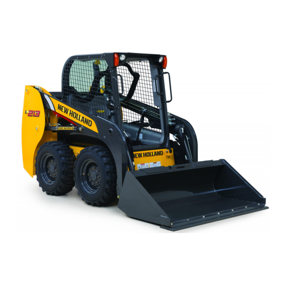
1 - GENERAL INFORMATION Machine components 93107444 (1) Steps (6) Service access cover (2) Hand-holds (7) Chain compartment access (3) Front lights (8) Bucket (4) Loader arm (9) Operator's compartment (5) Loader arm cylinder 1-10... -
Page 17: Safety Information
2 - SAFETY INFORMATION 2 - SAFETY INFORMATION###_2_### Safety rules and signal words Personal safety This is the safety alert symbol. It is used to alert you to potential personal injury hazards. Obey all safety messages that follow this symbol to avoid possible death or injury. Throughout this manual you will find the signal words DANGER, WARNING, and CAUTION followed by special in- structions. -
Page 18: Safety Rules
2 - SAFETY INFORMATION Safety rules General safety rules Use caution when you operate the machine on slopes. DO NOT attempt to remove material from any part of the Raised equipment, full tanks and other loads will change machine while it is being operated or while components the center of gravity of the machine. - Page 19 2 - SAFETY INFORMATION Before you leave the machine: When, due to exceptional circumstances, you would decide to keep the engine running after you leave Park the machine on a firm, level surface. the Operator’s station, then you must follow these Lower the loader arms and attachments to the precautions: ground.
- Page 20 2 - SAFETY INFORMATION Always have a qualified tire technician service the tires the air that can be ignited by high temperatures from weld- and wheels. If a tire has lost all pressure, take the tire and ing procedures performed on the wheel or rim. Removing wheel to a tire shop or your dealer for service.
- Page 21 2 - SAFETY INFORMATION Follow the manufacturer’s instructions when you store nal): Flush with water. Antidote (eyes): flush with water and handle batteries. for 15 minutes and seek medical attention immediately. Antidote (internal): Drink large quantities of water or milk. Battery post, terminals, and related accessories contain Do not induce vomiting.
- Page 22 2 - SAFETY INFORMATION DO NOT attach any device to the protective structure for • The mounting or suspension for the protective struc- pulling purposes. DO NOT drill holes to the protective ture, operator’s seat and suspension, seat belts and structure.
- Page 23 2 - SAFETY INFORMATION Do not leave equipment in raised position while parked Do not lift load higher than necessary. Lower loads to or during service, unless securely supported. Hydraulic transport. Remember to leave appropriate clearance to cylinders must be mechanically locked or supported if the ground and other obstacles.
-
Page 24: Utility Safety
2 - SAFETY INFORMATION Utility safety Call all utility companies before you perform YOU MUST FOLLOW safety precautions when you work near buried utility lines. any machine operation During operation it is likely that you will be working After you locate any buried utility lines, carefully dig a hole around or near buried utility lines that may include, but to the utility line by hand and/or with automatic vacuum are not limited to:... -
Page 25: Proper Entry And Exit
2 - SAFETY INFORMATION Proper entry and exit DANGER Crushing hazard! Do not enter or exit the operator's compartment while the loader arms are raised or unsupported. Rest the loader arms on the ground or verify that loader arm is being supported by the loader arm strut or loader arm lock pin before entering or exiting the operator's compartment. - Page 26 2 - SAFETY INFORMATION DANGER Crushing hazard! Do not enter or exit the operator's compartment while the loader arms are raised or unsupported. Rest the loader arms on the ground or verify that loader arm is being supported by the loader arm strut or loader arm lock pin before entering or exiting the operator's compartment.
-
Page 27: Starting And Stopping Precautions
2 - SAFETY INFORMATION Starting and stopping precautions • Walk around the machine and attachments to warn all • Use jumper cables only in the recommended manner. personnel who may be servicing the machine or are in Improper use can result in battery explosion or unex- the machine path prior to starting. -
Page 28: Seat Belt Precautions
2 - SAFETY INFORMATION Seat belt precautions Seat belts Seat belts must be worn at all times. • Check that bolts are tight on the seat bracket or mount- ing. Seat belt inspection and maintenance: • If belt is attached to seat, make sure seat or seat brack- •... - Page 29 2 - SAFETY INFORMATION Seat restraint bar (if equipped) The restraint bar must be down in the operating position before starting. Seat restraint bar in the raised position. 93109333 Seat restraint bar in the operating position. 93109307 2-13...
-
Page 30: Specific Precautions To This Machine
2 - SAFETY INFORMATION Specific precautions to this machine DANGER Crushing hazard! Do not enter or exit the operator's compartment while the loader arms are raised or unsupported. Rest the loader arms on the ground or verify that loader arm is being supported by the loader arm strut or loader arm lock pin before entering or exiting the operator's compartment. -
Page 31: Roll Over Protective Structure (Rops)
2 - SAFETY INFORMATION Roll Over Protective Structure (ROPS) DANGER Crushing hazard! DO NOT operate the machine with the Roll-Over Protective Structure (ROPS) removed. Remove the ROPS only for service or replacement. Failure to comply will result in death or serious injury. D0032A DANGER Crushing hazard! - Page 32 2 - SAFETY INFORMATION Seatbelt The seat belt is an important part of your ROPS. You must wear the seat belt at all times when you operate the machine. Before you operate this machine, always make sure that the ROPS and operator's seat belt are correctly installed. 2-16...
-
Page 33: Welding On The Machine
2 - SAFETY INFORMATION Welding on the machine DANGER Improper operation or service of this machine can result in an accident. Any unauthorized modifications made to this machine can have serious consequences. Consult an authorized dealer on changes, additions, or modifications that may be required for this machine. Do not make any unauthorized modifications. -
Page 34: Loader Arm Lock And Cab Tilt Procedure - Radial Lift Machines
2 - SAFETY INFORMATION Loader arm lock and cab tilt procedure - radial lift machines DANGER Crushing hazard! Do not enter or exit the operator's compartment while the loader arms are raised or unsupported. Rest the loader arms on the ground or verify that loader arm is being supported by the loader arm strut or loader arm lock pin before entering or exiting the operator's compartment. - Page 35 2 - SAFETY INFORMATION 7. Slowly raise the loader arm until the support strut (B) falls onto the cylinder rod (D). 8. Stop the engine. RAIL14SSL0418AA 9. Pull up on the override control knob (E) (red control knob near the right-hand side of the operator’s seat). The support strut (B) will brace against the top of the cylinder barrel (C) supporting the weight of the loader arm.
- Page 36 2 - SAFETY INFORMATION 2. Pull on the hand holds at the front of the machine until the cab is completely tilted forward. 93107498 3. Confirm that the red lock tube has lowered over the cab pivot linkage. If it has, the cab tilt position is now secure.
- Page 37 2 - SAFETY INFORMATION 3. Install the retaining nuts. Torque the nuts to 170 N·m (125 lb ft). 931001633 Unlock and lower the loader arm for machine operation DANGER Crushing hazard! The loader arm is unsupported during support strut removal. Do not enter or exit the opera- tor's compartment with an unsupported loader arm.
-
Page 38: Loader Arm Lock And Cab Tilt Procedure - Vertical Lift Machines
2 - SAFETY INFORMATION Loader arm lock and cab tilt procedure - vertical lift machines DANGER Crushing hazard! Do not enter or exit the operator's compartment while the loader arms are raised or unsupported. Rest the loader arms on the ground or verify that loader arm is being supported by the loader arm strut or loader arm lock pin before entering or exiting the operator's compartment. - Page 39 2 - SAFETY INFORMATION 6. Locate the loader arm lock lever on the right-hand side of the operator’s seat. 7. Rotate the lock lever toward the operator’s seat (clock- wise) to engage the lock support pin(s). 8. Stop the engine. RAIL16SSL0012AA 9.
- Page 40 2 - SAFETY INFORMATION 2. Pull on the hand holds at the front of the machine until the cab is completely tilted forward. RAPH11SSL0016BA 3. Confirm that the red lock tube has lowered over the cab pivot linkage. If it has, the cab tilt position is now secure.
- Page 41 2 - SAFETY INFORMATION 3. Install the retaining nuts. Torque the nuts to 170 N·m (125 lb ft). 931001633 Unlock and lower the loader arm for machine operation 1. Sit in the operator's seat, fasten the seat belt, pull the restraint bar down (if equipped), and start the engine.
-
Page 42: No Engine Power - Loader Arm Up And Down Control
2 - SAFETY INFORMATION No engine power - loader arm up and down control DANGER Crushing hazard! Do not enter or exit the operator's compartment while the loader arms are raised or unsupported. Rest the loader arms on the ground or verify that loader arm is being supported by the loader arm strut or loader arm lock pin before entering or exiting the operator's compartment. -
Page 43: Emergency Exit
2 - SAFETY INFORMATION Emergency exit The rear window can be removed to provide an exit for the operator in the event the front exit is blocked. To remove the rear window, pull on the tag (1) and remove the window molding strip. Push on the bottom half of the window to force it away from the molding. -
Page 44: Ecology And The Environment
CONSTRUCTION strongly recommends that you return ble to your country, and make sure that you understand all used batteries to a NEW HOLLAND CONSTRUCTION this legislation. Where no legislation exists, obtain in- dealer, who will dispose of the used batteries or recycle formation from suppliers of oils, filters, batteries, fuels, the used batteries properly. -
Page 45: Safety Signs
2 - SAFETY INFORMATION Safety signs WARNING Avoid injury! Make sure safety signs are legible. Clean safety signs regularly. Replace all damaged, missing, painted over, or illegible safety signs. See your dealer for replacement safety signs. If a safety sign is on a part that is replaced, make sure the new part has a safety sign. - Page 46 2 - SAFETY INFORMATION Following is a listing of Safety signs and locations. Read and understand them before operating the machine. DANGER CRUSH HAZARD Keep out of this area when lift arm is raised, unless lift arm is supported by the support strut. Failure to comply will result in death or serious injury.
- Page 47 2 - SAFETY INFORMATION CAUTION Flying debris. Stay clear. Failure to comply could result in minor or moderate injury. Quantity: 2 Part number: 84004739 84004739 D Location: On the track debris guard. One on each side of the machine. RAIL15SSL0357AA NOTE: Only applicable to Compact Track Loaders (CTL) models C227, C232, and C238.
- Page 48 931002327 NOTE: Read and understand the “Loader arm lock and cab tilt procedure - radial lift machines” page 2-18 in this manual. Only applicable to models L213, L215, and C227. 2-32...
- Page 49 2 - SAFETY INFORMATION WARNING CRUSH HAZARD Always engage the cab pivot support strut when the cab is tilted forward. Failure to comply could result in death or serious injury. Quantity: 2 Part number: 84394351 84394351_A Location: On each side of the Roll Over Protective Structure (ROPS) lock mechanism.
- Page 50 Part number: 175509A1 175509A1 Location: On the right-hand side of the engine on top of the starter. Models L213, L215, L218, and L220 only. 931002035 Location: On the left-hand side of the engine on top of the starter. Models L223, L225, L230, C227, C232, and C238 only.
- Page 51 Failure to comply could result in death or serious injury. Quantity: 1 Part number: 47739196 47739196_A Location: On top of the radiator under the hood. Model L213 only. RAIL16SSL0014AA Location: On top of the radiator under the hood. RAIL16SSL0015AA 2-35...
- Page 52 Failure to comply could result in death or serious injury. Quantity: 1 Part number: 84535230 RAPH12SSL0074AA Location: Under the hood, on top of the air cleaner bracket. Model L213 only. RAIL16SSL0034BA Location: Under the hood, on top of the radiator. RAIL16SSL0015AA 2-36...
- Page 53 Quantity: 1 Part number: 87658005 87658005_A Location: On top of the radiator under the hood. Model L213 only. RAIL16SSL0014AA Location: On top of the radiator under the hood. RAIL16SSL0015AA NOTE: Follow the procedures in the maintenance section of this manual.
- Page 54 WARNING Hot Surface Hazard. Stay clear. Failure to comply could result in death or serious injury. Quantity: 1 Part number: 47856202 47856202_A Location: On top of the radiator. Model L213 only. RAIL16SSL0014AA Location: On top of the radiator. RAIL16SSL0015AA 2-38...
- Page 55 Part number: 84367568 84367568_A Location: On the back side of the coupler cross member. Models L213 and L215 only. RAIL16SSL0011AA Location: On the back side of the front loader arm cross tube. Models L218, L220, L223, L225, L230, C227, C232, and C238.
- Page 56 Part number: 84367573 84367573_A Location: On the back side of the coupler cross member. Models L213 and L215 only. RAIL16SSL0011AA Location: On the back side of the front loader arm cross tube. Models L218, L220, L223, L225, L230, C227, C232, and C238.
- Page 57 2 - SAFETY INFORMATION WARNING CRUSH HAZARD Always engage the Loader Lift Arms support pin when Lift Arms are raised for service and/or maintenance. Failure to comply could result in death or serious injury. Quantity: 1 Part number: 47739940 47739940 Location: On the lower left-hand side of the operators seat, attached to the ROPS.
- Page 58 2 - SAFETY INFORMATION Model SAE Rated Operating Decal part Decal/placement location Capacity (ROC) number *L213 590 kg (1300 lb) 84350672 680 kg (1500 lb) *L215 84350653 818 kg (1800 lb) *L218 84373065 *L220 905 kg (2000 lb) 84350658 *L223...
- Page 59 Quantity: 1 Part number: 47757330 47757330 Location: On top of the radiator. Model L213 only. RAIL16SSL0014AA Location: On top of the radiator. RAIL16SSL0015AA NOTE: See “Organic Acid Technology (OAT) coolant“ 7-14 for more details.
- Page 60 2 - SAFETY INFORMATION 2-44...
-
Page 61: Controls And Instruments
3 - CONTROLS AND INSTRUMENTS 3 - CONTROLS AND INSTRUMENTS###_3_### ACCESS TO OPERATOR'S PLATFORM Door latches, cab Exterior door latch Push on the knob (1) to release the door for entry. The starter switch key may be used to lock the door. RAIL13SSL0706BA Interior door latch Push on the lever (1) to release the door latch and open... -
Page 62: Window Glass, Cab
3 - CONTROLS AND INSTRUMENTS Window glass, cab Opening and closing window glass NOTE: Machines may be equipped with either one of the styles shown. Follow the procedure that is applicable to your machine. Pivot lever window style Each sliding glass section, when equipped, has an indi- vidual lever for window opening adjustment. -
Page 63: Windshield Wiper And Washer Controls
3 - CONTROLS AND INSTRUMENTS Windshield wiper and washer controls Windshield wiper switch • This three position switch located on the left "A" post console turns the wiper ON, OFF and operates the washer fluid spray. • Off position (1). •... -
Page 64: Cab Air Louvers
3 - CONTROLS AND INSTRUMENTS Cab air louvers The air louvers (1) are located to the lower right and left of the operator and are adjustable for operator comfort. Air flow, direction and volume can be adjusted. For maximum defrosting, point louvers in direction of de- sired defrost area. -
Page 65: Operator's Seat
3 - CONTROLS AND INSTRUMENTS OPERATOR'S SEAT Standard seat The standard seat is adjustable fore and aft using adjust- ment lever (1). 93109314 Mechanical suspension seat The mechanical suspension seat is adjustable fore and aft using adjustment lever (1), and has a weight adjustment knob (2). -
Page 66: Seat Belt Operation
3 - CONTROLS AND INSTRUMENTS Seat belt operation WARNING Equipment failure could cause accident or injury! Always fasten the seat belt securely before you operate the machine. Inspect seat belt parts for wear and damage. Replace any and all worn or damaged parts of the seat belt prior to operation. Failure to comply could result in death or serious injury. -
Page 67: Shoulder Belt
3 - CONTROLS AND INSTRUMENTS Shoulder belt Pull the seat belt retractable half (1) across the operator and buckle securely with the buckle half (2). A shoulder belt (3) is available from your dealer. Some machine configurations are equipped with a shoulder belt. NOTE: A California required 3 inch webbing seat belt kit is available through dealer service parts. -
Page 68: Mechanical Hydraulic Controls
3 - CONTROLS AND INSTRUMENTS MECHANICAL HYDRAULIC CONTROLS Steering and travel Moving the machine WARNING Collision hazard! Always make sure the area behind the machine is clear of all persons, animals, and obstructions BE- FORE backing up. Failure to comply could result in death or serious injury. W0232A WARNING Loss of control hazard! -
Page 69: Turning The Machine
3 - CONTROLS AND INSTRUMENTS Turning the machine Pivot turn - power to only one side • To make a pivot turn left: hold the left steering control lever in neutral and move the right steering control lever forward. • To make a pivot turn right: hold the right steering control lever in neutral and move the left steering control lever forward. -
Page 70: Lift Arm And Bucket Controls
3 - CONTROLS AND INSTRUMENTS Lift arm and bucket controls Hand controls 93109347C Lift arm raise and lower control. • The left-hand control lever (1) controls the lift arm. The lift arm will raise by pivoting the handle “UP” to the out- side of the cab. -
Page 71: Foot Pedals
3 - CONTROLS AND INSTRUMENTS Foot pedals 931007501 Lift arm raise and lower control. • The lift arm is controlled by the left foot pedal (1) located on the floor and is marked with a decal. The lift arm is raised by depressing the heel (rear) of the pedal. -
Page 72: Electro Hydraulic Controls
3 - CONTROLS AND INSTRUMENTS ELECTRO HYDRAULIC CONTROLS Control pattern overview Standard H control pattern 93100555 A1 The chart below will give a description of the control lever functions. The left-hand control lever is represented by the letter (A) and the right-hand control lever by letter (B). (A) Left-hand control lever (B) Right-hand control lever Left side drive forward. -
Page 73: Standard Iso Control Pattern
3 - CONTROLS AND INSTRUMENTS Standard ISO control pattern RAIL14SSL0314FA The chart below will give a description of the control lever functions. The left-hand control lever is represented by the letter (A) and the right-hand control lever by letter (B). (A) Left-hand control lever (B) Right-hand control lever Drive forward. -
Page 74: H Control Pattern Steering And Travel
3 - CONTROLS AND INSTRUMENTS H control pattern steering and travel Hand controls WARNING Collision hazard! Always make sure the area behind the machine is clear of all persons, animals, and obstructions BE- FORE backing up. Failure to comply could result in death or serious injury. W0232A WARNING Loss of control hazard! -
Page 75: Moving The Machine
3 - CONTROLS AND INSTRUMENTS Moving the machine Push both the left-hand control lever (1) and the right- hand control lever (2) forward from neutral, to move the machine forward. Pull both of the control levers rear- ward from neutral, to move the machine in reverse. Move the control levers forward a short distance for maximum power and slow speed. -
Page 76: Turning The Machine
3 - CONTROLS AND INSTRUMENTS Turning the machine Pivot turn - power to only one side • To make a pivot turn left: hold the left-hand control lever in neutral and move the right-hand control lever forward. • To make a pivot turn right: hold the right-hand control lever in neutral and move the left-hand control lever for- ward. -
Page 77: H Control Pattern Lift Arm And Bucket Controls
3 - CONTROLS AND INSTRUMENTS H control pattern lift arm and bucket controls Lift arm raise/lower control 931007524 Lift arm raise and lower control. • The left-hand control lever (1) controls the lift arm. The lift arm will raise by pivoting the handle “UP” to the out- side of the cab. -
Page 78: Bucket Curl/Dump Control
3 - CONTROLS AND INSTRUMENTS Bucket curl/dump control 931007524 Bucket dump and curl control. • The right-hand control lever (2) controls the bucket. The bucket will dump by pivoting the handle “UP” to the out- side of the cab. Pivoting the handle “DOWN” to the in- side of the cab and the bucket will roll back (curl). -
Page 79: Iso Control Pattern Steering And Travel
3 - CONTROLS AND INSTRUMENTS ISO control pattern steering and travel Moving the machine WARNING Loss of control hazard! Keep hands and feet on the appropriate controls at all times to maintain control of the machine. Failure to comply could result in death or serious injury. W0237A WARNING Collision hazard! -
Page 80: Turning The Machine
3 - CONTROLS AND INSTRUMENTS Turning the machine Pivot turn - power to only one side • To make a pivot turn left: from neutral, push the left- hand control lever slightly forward, and then left to the 10:00 position. •... - Page 81 3 - CONTROLS AND INSTRUMENTS Gradual turn - power to both sides in the same direction • To make a gradual forward turn left: from neutral, push the left-hand control lever forward and slightly toward the 11:00 position. • To make a gradual forward turn right: from neutral, push the left-hand control lever forward and slightly toward the 1:00 position.
-
Page 82: Iso Control Pattern Lift Arm And Bucket Controls
3 - CONTROLS AND INSTRUMENTS ISO control pattern lift arm and bucket controls Lift arm and bucket controls 931007524 The right-hand control lever operates the lift arm and bucket. Lift arm raise and lower control. • Pull back on the right-hand control lever to raise (up) the lift arm. •... -
Page 83: Control Handles
3 - CONTROLS AND INSTRUMENTS CONTROL HANDLES Switch configurations The following functions can be activated from the control handles depending on your machine’s configuration. • Horn — Press the horn button to sound the horn. • Proportional auxiliary — Activate the hydraulic component attached to the standard or high flow auxiliary hydraulic ports. - Page 84 3 - CONTROLS AND INSTRUMENTS Level 200 Right side (1) Proportional auxiliary (2) Glide ride RAIL14SSL0309AA Left side (1) Turn signal (2) 2 Speed (3) Horn 93109405 Level 250 Right side (1) Proportional auxiliary (2) Float (3) Glide ride 93109408 Left side (1) Turn signal (2) 2 speed...
- Page 85 3 - CONTROLS AND INSTRUMENTS Level 300 Right side (1) Multi-functional #1 (2) Proportional auxiliary (3) Multi-functional #4 (4) Glide ride RAIL14SSL0311AA Left side (1) Multi-functional #2 (2) Multi-functional #3 (3) Turn signal (4) 2 speed (5) Horn 93109409 Level 350 Right side (1) Multi-functional #1 (2) Proportional auxiliary...
- Page 86 3 - CONTROLS AND INSTRUMENTS Level 400 Right side (1) Multi-functional #1 (2) Proportional auxiliary (3) Multi-functional #4 (4) Glide ride RAIL14SSL0311AA Left side (1) 2nd auxiliary hydraulics (2) Multi-functional #3 (3) Turn signal (4) 2 speed (5) Horn 93109409 Level 450 Right side (1) Multi-functional #1...
- Page 87 3 - CONTROLS AND INSTRUMENTS Level 550 Right side (1) Multi-functional #1 (2) Proportional auxiliary (3) Multi-functional #4 (4) Float (5) Glide ride 9310105522 Left side (1) High flow/Enhanced high flow auxiliary (2) Multi-functional #3 (3) Turn signal (4) 2 Speed (5) Horn 9310105523 3-27...
-
Page 88: Two-Speed Function
3 - CONTROLS AND INSTRUMENTS Two-speed function Two-Speed Function Press the top portion of the switch on the left-hand control lever to shift from first gear to second gear. NOTE: The two-speed indicator on the left-hand col- umn illuminates when the two-speed function is active. Press the bottom portion of the switch on the left- hand control lever once to downshift from second gear to... -
Page 89: Auxiliary Hydraulics
3 - CONTROLS AND INSTRUMENTS AUXILIARY HYDRAULICS Standard auxiliary hydraulics Follow the attachment’s operator’s manual on specific installation procedures, operation, and removal proce- dures. Auxiliary hydraulic couplers are located on the left-hand loader arm. 1. Work ports — 1/2 inch coupler size 2. - Page 90 3 - CONTROLS AND INSTRUMENTS Relieve pressure before disconnecting at- tachment hoses NOTICE: Before removing attachments, make sure that you relieve pressure from the hydraulic system BEFORE disconnecting the auxiliary hoses. If the pressure is not relieved, you WILL NOT be able to reattach hoses. 1.
-
Page 91: High Flow Auxiliary Hydraulics
3 - CONTROLS AND INSTRUMENTS High flow auxiliary hydraulics The high flow auxiliary hydraulic feature provides 207 bar (3000 psi) or limited to 132 l/min (35 US gpm) to the aux- iliary circuit. Follow the attachment’s operator’s manual on specific installation procedures, operation, and removal procedures. - Page 92 3 - CONTROLS AND INSTRUMENTS NOTICE: Before removing attachments, make sure that you relieve pressure from the hydraulic system BEFORE disconnecting the auxiliary hoses. If the pressure is not relieved, you WILL NOT be able to reattach hoses. The high flow 5/8 inch quick disconnects on the machine do not have the ability to relieve pressure when connecting or disconnecting, but the following procedure shows how to release the pressure.
-
Page 93: Enhanced High Flow (Ehf) Auxiliary Hydraulics
3 - CONTROLS AND INSTRUMENTS Enhanced High Flow (EHF) auxiliary hydraulics The Enhanced High Flow (EHF) auxiliary hydraulic feature provides 276 bar (4000 psi) or 132 l/min (35 US gpm) to the auxiliary circuit. Follow the attachment’s operator’s manual on specific installation procedures, operation, and removal procedures. - Page 94 3 - CONTROLS AND INSTRUMENTS Disconnect the attachment NOTE: Unlike the standard auxiliary hydraulics or the high flow auxiliary hydraulics you do not have to release hy- draulic pressure from the system before disconnecting the attachments auxiliary hoses. 1. Lower the loader arm all the way down and ensure that the loader arm or attachment is not supporting the weight of the machine with the front wheels off the ground.
-
Page 95: Instrument Cluster
3 - CONTROLS AND INSTRUMENTS INSTRUMENT CLUSTER Electronic Instrument Cluster (EIC) The Electronic Instrument Cluster (EIC) is on the right- hand cab post. Once in the seat, the alarm sounds and selected lamps illuminate briefly. Monitor these lamps on a daily basis to confirm that they will function in the event of a system alarm. - Page 96 3 - CONTROLS AND INSTRUMENTS KEY SWITCH (four position) NOTE: Follow the starting procedure 4-3 de- scribed in this manual. Accessory position Turn the key to the left, the machine’s electrical system is now active. NOTICE: Do not leave the key in this position otherwise you may drain the battery power.
- Page 97 3 - CONTROLS AND INSTRUMENTS HYDRAULIC SYSTEM MALFUNCTION Yellow Lamp will flash when a hydraulic fault is detected. Use the fault code that appeared in text display and reference it in the trouble shooting section of this manual. ELECTRONIC SYSTEM MALFUNCTION This yellow lamp will flash and the alarm will sound.
- Page 98 3 - CONTROLS AND INSTRUMENTS FUNCTION BUTTON Use this, when in the “Setup” menu, as the "enter" data key NOTE: This button is used for user code lock and unlock. (10) FUNCTION BUTTON Use this when in the “Setup” menu, also used to scroll within the setup menu.
- Page 99 3 - CONTROLS AND INSTRUMENTS (13) H / ISO control pattern selector, if equipped This selects the drive pattern type of hand control operation. Read the proper steps listed in this chapter to activate. (14) WORK LIGHTS This knob controls the external working lights and road lights.
- Page 100 3 - CONTROLS AND INSTRUMENTS (15) FUEL GAUGE: The fuel gauge consists of a series of bars that indicate the level of fuel in the fuel tank. When all 8 bars are visible the fuel tank is full. Bottom bar flashing indicates approximately 3.8 L (1.0 US gal) of fuel remaining.
- Page 101 3 - CONTROLS AND INSTRUMENTS (18) TEXT DISPLAY: This display will show the following during normal operation, as selected by the operator. • Engine hours: Engine hours will always be displayed momentarily when the operator initially sits in the seat. The operator may choose to leave engine hours on display continuously or select one of the following.
-
Page 102: Advanced Instrument Cluster (Aic)
3 - CONTROLS AND INSTRUMENTS Advanced Instrument Cluster (AIC) The Advanced Instrument Cluster (AIC) is on the right- hand cab post. Once in the seat, the alarm sounds and selected lamps illuminate briefly. Monitor these lamps on a daily basis to confirm that they will function in the event of a system alarm. - Page 103 3 - CONTROLS AND INSTRUMENTS STOP Severe warning requiring immediate shut down, RED lamp will flash and audible alarm will sound. Use the fault code that appeared in text display and reference it in the trouble shooting section of this manual. ENGINE MALFUNCTION Yellow Lamp will flash when an engine fault is detected.
- Page 104 3 - CONTROLS AND INSTRUMENTS SEAT BELT RED lamp will illuminate when the seat belt is unlatched or the restraint bar (if equipped) is raised. RED lamp will also illuminate when the operator leaves the operator’s seat. PARK BRAKE LAMP: This Red lamp illuminates to indicate the park brake is engaged.
- Page 105 3 - CONTROLS AND INSTRUMENTS POWER: Push for Start-up power or push for engine shut down. Use this, when in the “Setup” menu, as the "enter" Data Key. NOTE: This button is used for user code lock and unlock. START: NOTE: Follow the starting procedure de- scribed in this manual.
- Page 106 3 - CONTROLS AND INSTRUMENTS (12) H / ISO control pattern selector, if equipped This selects the drive pattern type of hand control operation. Read the proper steps listed in this chapter to activate. (13) WORK LIGHTS This knob controls the external working lights and road lights.
- Page 107 3 - CONTROLS AND INSTRUMENTS (14) FUEL GAUGE: The fuel gauge consists of a series of bars that indicate the level of fuel in the fuel tank. When all 8 bars are visible the fuel tank is full. Bottom bar flashing indicates approximately 3.8 L (1.0 US gal) of fuel remaining.
- Page 108 3 - CONTROLS AND INSTRUMENTS (17) TEXT DISPLAY: This display will show the following during normal operation, as selected by the operator. • Engine Hours: Engine hours will always be displayed momentarily when the operator initially sits in the seat. The operator may choose to leave engine hours on display continuously or select one of the following.
-
Page 109: Instrument Cluster
3 - CONTROLS AND INSTRUMENTS Instrument cluster Menu navigation controls Use the four switch buttons to navigate through the instru- ment cluster Menu by following the setup menu functions. Many of the setup menu functions are intended for ser- vice technicians and owners. Contact your dealer for the service manual or security code information. -
Page 110: Instrument Cluster Setup Menu
3 - CONTROLS AND INSTRUMENTS Instrument cluster SETUP menu NOTE: The Advanced Instrument Cluster (AIC) images are shown in this section for the four switch buttons (2), (3), (4), and (5) used to navigate through the instrument cluster. The top two switch buttons on the Electronic Instrument Cluster (EIC) are function buttons and function the same as the POWER (5) and START (2) switch buttons on the AIC instrument panel for the setup menu functions. -
Page 111: Instrument Cluster Display Setting
3 - CONTROLS AND INSTRUMENTS Instrument cluster display setting NOTE: The Advanced Instrument Cluster (AIC) images are shown in this section for the four switch buttons (2), (3), (4), and (5) used to navigate through the instrument cluster. The top two switch buttons on the Electronic Instrument Cluster (EIC) are function buttons and function the same as the POWER (5) and START (2) switch buttons on the AIC instrument panel for the setup menu functions. -
Page 112: Electro-Hydraulic (Eh) Controllability Selection
3 - CONTROLS AND INSTRUMENTS Electro-Hydraulic (EH) controllability selection Setting controllability with Easy-Electro–Hy- draulic (EZ-EH) The Easy Electro-Hydraulic ( EZ-EH) machines have the EZ-EH information sign located at the top of the instru- ment cluster on the right-hand column. The following instructions are for the shortcut to the Electro-Hydraulic (EH) setup. - Page 113 3 - CONTROLS AND INSTRUMENTS Easy-Electro-Hydraulic (EZ-EH) Flow chart RAIL13SSL0727GA Customize settings • Custom settings SP-C and CR-C allow you to fully customize the EH settings using the setup menu. • SP-C sets to the SETUP menu SPEEd settings: DRIVE, LIFT, and TILT. CR-C sets to setup menu CRTL settings DRIVE and L-ARM.
- Page 114 3 - CONTROLS AND INSTRUMENTS Setting custom controllability settings for Electro–Hydraulic (EH) NOTE: These settings can be activated using the Easy Electro-Hydraulic (EZ-EH) menu custom settings SP-C and CR-C. All changes must be made with the engine in the off posi- tion and the electronics asleep.
- Page 115 Travel forward and reverse function. LDR2 Medium response to control lever movement. Lift Loader arm up and down function. LDR3 Smooth response to control lever movement. Default settings for models L213 and L215 SPEED Tilt Med-1 Med-2 High Lift Med-1 Med-2...
- Page 116 3 - CONTROLS AND INSTRUMENTS SPEED L-Arm LDR3 LDR2 LDR1 Default settings for models L223, L225 and L230 SPEED Tilt Med-1 Med-2 High Lift Med-1 Med-2 High Drive Med-1 Med-2 High CTRL Drive DRV3 DRV2 DRV1 L-Arm LDR3 LDR2 LDR1 Default settings for models C227, C232 and C238 SPEED Tilt...
-
Page 117: Temperature Display Selection
3 - CONTROLS AND INSTRUMENTS Temperature display selection NOTE: The Advanced Instrument Cluster (AIC) images are shown in this section for the four switch buttons (2), (3), (4), and (5) used to navigate through the instrument cluster. The top two switch buttons on the Electronic Instrument Cluster (EIC) are function buttons and function the same as the POWER (5) and START (2) switch buttons on the AIC instrument panel for the setup menu functions. -
Page 118: View Or Reset Job Timer (Jtime)
3 - CONTROLS AND INSTRUMENTS View or reset Job Timer (JTIME) NOTE: The Advanced Instrument Cluster (AIC) images are shown in this section for the four switch buttons (2), (3), (4), and (5) used to navigate through the instrument cluster. The top two switch buttons on the Electronic Instrument Cluster (EIC) are function buttons and function the same as the POWER (5) and START (2) switch buttons on the AIC instrument panel for the setup menu functions. -
Page 119: Anti-Theft Protection
3 - CONTROLS AND INSTRUMENTS Anti-theft protection NOTE: The Advanced Instrument Cluster (AIC) images are shown in this section for the four switch buttons (2), (3), (4), and (5) used to navigate through the instrument cluster. The top two switch buttons on the Electronic Instrument Cluster (EIC) are function buttons and function the same as the POWER (5) and START (2) switch buttons on the AIC instrument panel for the setup menu functions. - Page 120 3 - CONTROLS AND INSTRUMENTS If no owner code has been created 1. If you decide you do not want to create a code, enter all 0s (A), you will return to OWNCR. RAIL14SSL0166GA 3-60...
- Page 121 3 - CONTROLS AND INSTRUMENTS Creating codes The panel cannot be locked until a code is created. The instrument panel has one owner code and up to ten user codes. The owner code will always unlock the panel. The owner code will be required to create or change user codes and to modify the owner code.
- Page 122 3 - CONTROLS AND INSTRUMENTS If an owner code has been created and LOCK function is disabled NOTE: You can set the lock function to one of three settings OFF, MANUAL LOCK, or AUTO LOCK by pressing the POWER button at point (C) as shown in the Figure below. 1.
- Page 123 3 - CONTROLS AND INSTRUMENTS To modify the owner code: Once in the LOCK menu, the display will show OWNER. Press the POWER button to enter the OWNER menu. The display will show open followed by 00000. 1. Enter the current owner code by using multiple presses of the START button (2), AUX OVERRIDE button (4), and OPERATE button (3).
- Page 124 3 - CONTROLS AND INSTRUMENTS User codes Once in the “Setup” menu, press the START button to move to the LOCK menu. Press the POWER button to enter the LOCK menu. To create or modify a user code: NOTE: An owner code must be saved before a user code. Once in the LOCK menu, the display will show the word OWNER.
-
Page 125: Left-Hand Column Switch Identification
3 - CONTROLS AND INSTRUMENTS Left-hand column switch identification Heating, Ventilation, Air-Conditioning (HVAC) dial Rotate this dial to adjust temperature. Fan dial Rotate this dial to activate the fan. Air-conditioning switch The lamp will illuminate, to confirm the system is operational, once the fan switch has been activated. - Page 126 3 - CONTROLS AND INSTRUMENTS Rotating beacon switch If equipped, push the switch to activate the rotating beacon. Hazard flasher switch If equipped, push the switch to activate the 4-way flashers. Self-leveling switch If equipped, use this switch to activate the self-leveling feature.
- Page 127 3 - CONTROLS AND INSTRUMENTS (12) Loader lockout switch If equipped, push to disable loader control while roading the unit. The bucket and loader arm will be locked in the position they are in when the loader lockout switch is pressed to the ON position.
-
Page 128: Iso Or H Pattern Control Switch
3 - CONTROLS AND INSTRUMENTS ISO or H pattern control switch On machines with ISO or H drive, switch (1) determines which drive system the machine is operating. ISO drive (single lever controls drive) or H drive (traditional 2 lever drive control). -
Page 129: Machine Lights
3 - CONTROLS AND INSTRUMENTS Machine lights Activate the cab exterior lights (if equipped) by a rotary switch (1) on the bottom of the right-hand instrument panel. The rotary switch (1): • remains in the last position that you select. •... - Page 130 3 - CONTROLS AND INSTRUMENTS 3-70...
-
Page 131: Operating Instructions
4 - OPERATING INSTRUCTIONS 4 - OPERATING INSTRUCTIONS###_4_### COMMISSIONING THE UNIT Operating Instructions Before each operating period, it is the responsibility of the operator to confirm that the machine is safe and serviced. During the first 20 h of operation, make sure to do the 4. - Page 132 4 - OPERATING INSTRUCTIONS Pre - start checklist Operating and environmental conditions must be Confirm that all safety signs are legible and prop- considered and the following checked: erly placed on the correct component. Replace any safety signs that are not legible. Contact your dealer Fill the tank with No.
-
Page 133: Starting The Unit
4 - OPERATING INSTRUCTIONS STARTING THE UNIT Engine operation DANGER Improper operation or service of this machine can result in an accident. Do not operate this machine or perform any lubrication, maintenance, or repair on it until you have read and understood the operation, lubrication, maintenance, and repair information. Failure to comply will result in death or serious injury. - Page 134 4 - OPERATING INSTRUCTIONS Starting the engine When the operator sits in the seat the instrument cluster panel will light all functions for about 3 s, during this time the instrument cluster is self-checking the electrical circuits. All lights will go off except the parking brake and the fasten seat belt light will flash until the seat belt is buckled or the restraint bar (if equipped) is lowered.
-
Page 135: Operating In Extreme Temperatures
See your dealer for additional starting aids. Cooling system Keep the coolant at the correct level in the reservoir and radiator. Use NEW HOLLAND AMBRA ACTIFULL™ OT EXTENDED LIFE COOLANT premix ( 50% concentrate and 50% distilled water). This mixture protects the engine cooling system to -35.0 °C (-31.0 °F). -
Page 136: Throttle
4 - OPERATING INSTRUCTIONS Throttle Hand throttle Manual throttle control lever in the low idle position. NOTE: If the throttle control lever is not in the low idle position when starting the engine, the engine speed will be limited to low idle until the throttle control lever is returned to the low idle position. -
Page 137: Booster Battery Procedure
4 - OPERATING INSTRUCTIONS Booster battery procedure WARNING Hazardous chemicals! Battery electrolyte contains sulfuric acid. Contact with skin and eyes could result in severe irritation and burns. Always wear splash-proof goggles and protective clothing (gloves and aprons). Wash hands after handling. Failure to comply could result in death or serious injury. -
Page 138: Stopping The Unit
4 - OPERATING INSTRUCTIONS STOPPING THE UNIT Parking the machine and stopping the engine WARNING Equipment rolling hazard! Always try to park the machine on firm level ground. Avoid parking on slopes. Block the wheels in both directions. Failure to comply could result in death or serious injury. W0265A WARNING Fall hazard! -
Page 139: Moving The Unit
4 - OPERATING INSTRUCTIONS MOVING THE UNIT Machine operation WARNING Loss of control hazard! Keep hands and feet on the appropriate controls at all times to maintain control of the machine. Failure to comply could result in death or serious injury. W0237A WARNING Impact hazard! - Page 140 4 - OPERATING INSTRUCTIONS NOTICE: For all machines (mechanical or EH), if the operator is out of the seat, the seat belt is not fasten or un- plugged, the restraint bar (if equipped) is unplugged, and the OPERATE button is pressed, error message OPRPR will appear on the display.
-
Page 141: Transport Operations
5 - TRANSPORT OPERATIONS 5 - TRANSPORT OPERATIONS###_5_### SHIPPING TRANSPORT Transporting the machine WARNING Transport hazard! The machine can slip or fall from a ramp or trailer. Make sure the ramp and trailer are not slippery. Remove all oil, grease, ice, etc. Move the machine on or off the trailer with machine centered on the trailer or ramp. - Page 142 5 - TRANSPORT OPERATIONS You must know the rules or laws for safety that are used in each area that you will be in. Make sure that your truck and machine are equipped with the correct safety equip- ment. Load the machine on to a trailer: 1.
- Page 143 5 - TRANSPORT OPERATIONS Lifting the machine with a four-point lifting device WARNING Heavy objects! Lift and handle all heavy components using lifting equipment with adequate capacity. Always support units or parts with suitable slings or hooks. Make sure the work area is clear of all bystanders. Failure to comply could result in death or serious injury.
- Page 144 5 - TRANSPORT OPERATIONS L213 and L215 only Front sling requirements: • Two synthetic slings 3.7 m (12.0 ft) in length. • Each sling must have a rated lifting capacity of equal to or greater than 0.706 x Gross Vehicle Weight (GVW).
- Page 145 5 - TRANSPORT OPERATIONS 1. Connect all slings to a single point (1) on the suitable craning equipment above the cab. 2. Attach chains to the machine’s rear lifting points (2) on the machine. RAIL14SSL0406BA 3. Route the front sling down the right-hand side of the Roll Over Protective Structure (ROPS).
- Page 146 5 - TRANSPORT OPERATIONS C227 only Front sling requirements: • Two synthetic slings 3.7 m (12.0 ft) in length. • Each sling must have a rated lifting capacity of equal to or greater than 0.741 x Gross Vehicle Weight (GVW). Rear sling requirements: •...
- Page 147 5 - TRANSPORT OPERATIONS 1. Connect all slings to a single point (1) on the suitable craning equipment above the cab. 2. Attach chains to the machine’s rear lifting points (2) on the machine. RAIL14SSL0397BA 3. Route the front sling down the right-hand side of the Roll Over Protective Structure (ROPS).
- Page 148 5 - TRANSPORT OPERATIONS L218 and L220 only Front sling requirements: • Two synthetic slings 3.7 m (12.0 ft) in length. • Each sling must have a rated lifting capacity of equal to or greater than 0.552 x Gross Vehicle Weight (GVW). Rear sling requirements: •...
- Page 149 5 - TRANSPORT OPERATIONS 1. Connect all slings to a single point (1) on the suitable craning equipment above the cab. 2. Attach chains to the machine’s rear lifting points (2) on the machine. RAIL14SSL0402BA 3. Route the front sling down the right-hand side of the Roll Over Protective Structure (ROPS).
- Page 150 5 - TRANSPORT OPERATIONS L223, L225, L230, C232, and C238 only Front sling requirements: • Two synthetic slings 3.7 m (12.0 ft) in length. • Each sling must have a rated lifting capacity of equal to or greater than 0.501 x Gross Vehicle Weight (GVW). Rear sling requirements: •...
- Page 151 5 - TRANSPORT OPERATIONS 1. Connect all slings to a single point (1) on the suitable craning equipment above the cab. 2. Attach chains to the machine’s rear lifting points (2) on the machine. RAIL14SSL0412BA 3. Route the front sling down the right-hand side of the Roll Over Protective Structure (ROPS).
- Page 152 1. Remove any and all attachments before lifting the ma- chine. 2. Only use a NEW HOLLAND CONSTRUCTION ap- proved single-point lifting attachment specifically de- signed for your machine. Confirm all four hardware (1) locations are properly tightened (right-hand side lower hardware not shown).
-
Page 153: Recovery Transport
Failure to comply could result in death or serious injury. W0126A NOTICE: NEW HOLLAND CONSTRUCTION does not recommend towing the machine. Do not attempt to move the machine if you believe more damage to the machine will occur. You may damage the machine more severely if you attempt to tow or move a disabled machine. - Page 154 5 - TRANSPORT OPERATIONS 5-14...
-
Page 155: Working Operations
6 - WORKING OPERATIONS 6 - WORKING OPERATIONS###_6_### GENERAL INFORMATION Mechanical attachment mounting systems WARNING Unexpected machine movement! Always make sure the machine is at operating temperature before mounting or removing tools or at- tachments. Failure to comply could result in death or serious injury. W0184A WARNING Crushing hazard! - Page 156 6 - WORKING OPERATIONS Installing the attachment NOTICE: Read the manufacturer’s instruction manual for attachments not included in this manual. A pivoting coupler (1) is supplied with the skid steer as standard equipment and remains attached to the loader lift arm. 931007516A 1.
- Page 157 6 - WORKING OPERATIONS 3. Raise and curl the coupler until the back surface of the attachment comes to rest flat against the front surface of the coupler. 4. When the attachment is fully supported, lower the lift arm until the lift arm is completely down on the loader stops.
-
Page 158: Hydraulic Attachment Mounting Systems
6 - WORKING OPERATIONS Hydraulic attachment mounting systems The optional hydraulic coupler allows the operator to remain in the operator seat and quickly change the loader arm attachments. The hydraulic coupler switch must be used in conjunction with the one of the three hydraulic functions (held to the end of its stroke): •... - Page 159 6 - WORKING OPERATIONS Installing the attachment 1. Confirm the red markings on the indicator pins (2) are visible (unlock position). If the red markings are not visible, press and hold the hydraulic coupler switch (1) in the unlock direction. With the other hand activate and hold the control lever’s auxiliary switch.
-
Page 160: Field Operation
6 - WORKING OPERATIONS Field operation WARNING Equipment failure could cause accident or injury! Always fasten the seat belt securely before you operate the machine. Inspect seat belt parts for wear and damage. Replace any and all worn or damaged parts of the seat belt prior to operation. Failure to comply could result in death or serious injury. - Page 161 6 - WORKING OPERATIONS Job layout For efficient operation, arrange the job to minimize the time required to perform the work cycle. In spotting the dump site, consider wind direction and ground slope. Whenever possible, position the dump site so that the wind will carry dust away from the operator.
- Page 162 6 - WORKING OPERATIONS Filling the bucket There are two basic methods of filling a bucket from a pile: arc penetration and step penetration. Judge the type of penetration needed for loading and vary the methods to suit the materials. Arc penetration With the arc penetration method, the bucket is forced into the pile and rolled back while raised in a continuous upward arc until the bucket is filled.
- Page 163 6 - WORKING OPERATIONS Digging WARNING Loss of control hazard! Travel speed should be such that complete control and machine stability is maintained at all times. Where possible, avoid operating near ditches, embankments and holes. Reduce speed when turning, crossing slopes, and on rough, slick, or muddy surfaces. Failure to comply could result in death or serious injury.
- Page 164 6 - WORKING OPERATIONS Returning the bucket load to the loading position Immediately after the bucket has been fully dumped, begin the roll back cycle as the machine is backed away from the dump site. Repositioning the bucket for the filling cycle while lowering the lift arms is a good time saver. Fine adjustments in bucket height can be made as the skid steer begins forward on the filling cycle, thereby saving a period of dead time between the dumping and filling cycles.
-
Page 165: Maintenance
Failure to comply could result in death or serious injury. W0051A NOTICE: While any company can perform necessary maintenance or repairs on your equipment, NEW HOLLAND CONSTRUCTION strongly recommends that you use only authorized NEW HOLLAND CONSTRUCTION dealers and products that meet the given specifications. Improperly or incorrectly performed maintenance and repair voids... - Page 166 7 - MAINTENANCE NOTE: Read the safety decals and instructional decals on the machine. Read the operator's manual and safety manual. Understand the operation of the machine before you start servicing. NOTE: Use the correct safety clothing and safety equip- ment.
-
Page 167: Lubrication Analysis Program
7 - MAINTENANCE Lubrication analysis program Ask your dealer about a lubricant analysis program. Through this service, your lubricants are tested in an independent laboratory. You simply remove a sample of lubricant from your machine and send the sample to the independent laboratory. -
Page 168: Machine Cleaning
7 - MAINTENANCE Machine cleaning WARNING Fire hazard! Failure to inspect and clean machine and engine compartment could result in reduced machine per- formance, machine damage, and increased risk of fire. Fire can result in total loss of vehicle and property, and may cause serious personal injury. -
Page 169: Cab Door Removal And Installation
7 - MAINTENANCE Cab door removal and installation NOTICE: During the removal process retain all door hinge shims and keep in a secure location. The shims are re- quired for a proper fit when installing the door at a later date. 1. -
Page 170: Battery Safety - Check And Cleaning
7 - MAINTENANCE Battery safety - check and cleaning WARNING Battery acid causes burns. Batteries contain sulfuric acid. Battery electrolyte contains sulfuric acid. Contact with skin and eyes could result in severe irritation and burns. Always wear splash-proof goggles and protective clothing (gloves and aprons). Wash hands after handling. - Page 171 7 - MAINTENANCE WARNING Hazardous chemicals! Battery electrolyte contains sulfuric acid. Contact with skin and eyes could result in severe irritation and burns. Always wear splash-proof goggles and protective clothing (gloves and aprons). Wash hands after handling. Failure to comply could result in death or serious injury. W0006A 63107490 Check the battery as required, for dirt corrosion and damage.
-
Page 172: Battery Disconnect Switch
7 - MAINTENANCE Battery disconnect switch NOTE: The battery disconnect switch is an optional fea- ture. Use the battery disconnect switch the enable or disable electrical power from the machine batteries to the electrical components. 1. Open the engine hood and rear service door. Engage the rear service door latch (1) located near the lower hinge. -
Page 173: Engine Hourmeter
7 - MAINTENANCE Engine hourmeter NOTE: The display shown is an Advanced Instrument Cluster (AIC). The procedure is the same for both AIC and Electronic Instrument Cluster (EIC) displays. Service your machine at the intervals and locations given in the maintenance and lubrication chart. When you ser- vice your machine, use only high quality lubricants. -
Page 174: Fluids And Lubricants
15.6 l (4.2 US gal) L223, L225, L230, C232, C238 19 l (5 US gal) C227 17 l (4.5 US gal) Specifications NEW HOLLAND AMBRA ACTIFULL™ OT EXTENDED LIFE COOLANT Hydraulic system Reservoir capacity 15.0 l (3.96 US gal) System capacity: L213, L215 29.2 l (7.7 US gal) -
Page 175: Engine Oils
See the following chart for recommended viscosity at varying ambient air temperature ranges. NOTE: Do not put performance additives or other oil additive products in the engine crankcase. NEW HOLLAND CON- STRUCTION develops the oil change intervals given in this manual from tests with NEW HOLLAND CONSTRUCTION lubricants. -
Page 176: Hydraulic Oil Viscosity
38 °C (100 °F) ambient temperature or frequent roading applications (above 20 to 30 minutes) are common. NOTE: NEW HOLLAND CONSTRUCTION recommends NEW HOLLAND AMBRA HYDROSYSTEM 46 HV for im- proved cold weather operation. Standard factory fill oil T ™... -
Page 177: Biodiesel Fuel
NOTICE: It is imperative that you check which blend is ap- ter life. In cold weather, this is more likely to happen. Con- proved for your engine with your NEW HOLLAND CON- sult your NEW HOLLAND CONSTRUCTION dealer for STRUCTION dealer. Be aware that the use of Biodiesel... -
Page 178: Organic Acid Technology (Oat) Coolant
EAVY OOLANT FREEZE tion such as NEW HOLLAND AMBRA ACTIFULL™ OT EXTENDED LIFE COOLANT. You can easily identify NEW HOLLAND AMBRA ACTIFULL™ OT EXTENDED LIFE COOLANT by its yellow color. You should never mix the coolant types. The coolant solution used must meet the following CNH Industrial material specifications for either coolant type: •... - Page 179 7 - MAINTENANCE You may notice the older version of the OAT decal (CNH Industrial part number 47488993) on some applications. Definitions Conventional coolant: A coolant that relies on inorganic inhibitors such as sil- icates, nitrites, and phosphates for corrosion and cavi- tation protection.
-
Page 180: Lubrication And Maintenance Access
7 - MAINTENANCE Lubrication and maintenance access 1. Open the engine compartment hood by pivoting up- ward. NOTE: This style hood may be locked with a padlock. 2. Lift up on the latch tab to open the rear service door. 93106858 The open engine hood and rear access door (1) will allow the operator or technician to:... - Page 181 7 - MAINTENANCE Open the rear service door to access the following: • Hydraulic oil fill (3). • Hydraulic oil level indicator sight glass (4). NOTE: If the hydraulic oil fill cap is to be removed, wipe clean before removing to prevent hydraulic system con- tamination.
-
Page 182: Fuses And Relays
7 - MAINTENANCE Fuses and relays L213 and L215 machines with mechanical controls 47946331B L218, L220, L223, L225, L230, C227, C232, and C238 machines with mechanical controls 47946329A 7-18... - Page 183 7 - MAINTENANCE Fuse and relays in the cab area – Mechanical controls only 1. Remove all the screws (1) from the cover panel (2) to expose the fuse and relay blocks. NOTE: The fuse and relay identification decal is on the back side of the cover panel.
- Page 184 7 - MAINTENANCE L213 and L215 machines with Electro-Hydraulic (EH) controls 47946332B 7-20...
- Page 185 7 - MAINTENANCE L218, L220, L223, L225, L230, C227, C232, and C238 machines with Electro-Hydraulic (EH) controls 47946330A 7-21...
- Page 186 7 - MAINTENANCE Fuse and relays in the cab area – Electro-Hydraulic (EH) controls only 1. Remove the screws (1) from the cover panel to expose the fuse and relay blocks. NOTE: The fuse and relay identification decal is on the back side of the cover panel.
- Page 187 Tilt the cab forward. See “Loader arm lock and cab tilt procedure - radial lift machines” 2-18 or “Loader arm lock and cab tilt procedure - vertical lift machines” 2-22. L213 and L215 relays Relay identification • Pre-heat power relay (1) •...
- Page 188 7 - MAINTENANCE L223, L225, L230, C232, and C238 relays Relay identification • Flasher relay (1) (if equipped with turn signals) • Pre-heat power relay (2) • Telematics module (3) (if equipped with Telematics) RAIL15SSL0130BA 7-24...
-
Page 189: Maintenance Chart
7 - MAINTENANCE MAINTENANCE CHART Maintenance chart Grease Change fluid Cleaning Drain fluid Check Replace Maintenance action Page no. INITIAL 10 HOURS Track tension check and adjustment 7-26 Tire pressure and wheel hardware torque 7-27 Alternator and air conditioning compressor (if equipped) belt 7-29 tension EVERY 10 HOURS OR EACH DAY... -
Page 190: Initial 10 Hours
7 - MAINTENANCE INITIAL 10 HOURS Track tension check and adjustment Check the track tension after the first 10 h on a new machine or if new tracks have been installed. After the initial 10 h check, the track tension should be checked every 50 h thereafter. For this procedure, the tracks, rollers, idler wheels, debris guard, and final drive sprockets must be clean of dirt and debris. -
Page 191: Tire Pressure And Wheel Hardware Torque
7 - MAINTENANCE Tire pressure and wheel hardware torque WARNING Explosion hazard! Always maintain correct tire pressure as indicated in this manual. DO NOT inflate tires above the recommended pressure. Excessive pressure could result in tire failure. Failure to comply could result in death or serious injury. W0109A WARNING Explosion hazard! - Page 192 7 - MAINTENANCE Wheel torque 63109344 1. Check that the wheel nuts have the proper torque set- ting. Wheel taper nut torque 169.5 N·m (125 lb ft) Flange nut 203.5 N·m (150 lb ft) 2. If necessary, tighten the nuts in a cross-pattern se- quence as shown.
-
Page 193: Alternator And Air Conditioning Compressor (If Equipped) Belt Tension
Alternator and air conditioning compressor (if equipped) belt tension NOTE: The alternator belt and air-conditioning belt tension check and adjust procedure only apples to models L213, L215, L218, and L220. Check the alternator belt tension after the first 10 h of operation on a new machine or if a new belt has been installed. -
Page 194: Every 10 Hours Or Each Day
7 - MAINTENANCE EVERY 10 HOURS OR EACH DAY Clean tracks and components Clean the components in the illustration every 10 h or daily, and when the machine has worked in muddy conditions. RAIL15SSL0395FA Rubber track Track debris guard Final drive sprocket (1 each side) Track roller wheels (4 or 3 on each side) Track adjustment access cover (1 each side) Rear idler wheel (1 each side) - Page 195 7 - MAINTENANCE 1. Raise the engine hood and ensure it stays in the open position. Lift up on the latch to open the rear service door. Use the service lock (1) in the lower right to se- cure the door in the open position. 2.
-
Page 196: Engine Coolant Level
You can use a refractometer to check the concentration level. You should not use Supplemen- tal Coolant Additives (SCA) when using NEW HOLLAND AMBRA ACTIFULL™ OT EXTENDED LIFE COOLANT. See “Organic Acid Technology (OAT) coolant” 7-14 for more details. - Page 197 7 - MAINTENANCE 6. The coolant level must be up to the radiator top, just un- der the overflow tube. Only add NEW HOLLAND AM- BRA ACTIFULL™ OT EXTENDED LIFE COOLANT to the radiator. BT04H069-01 7-33...
-
Page 198: Engine Oil Level
During the first 20 h of operation check the oil level at one hour intervals. After the initial 20 h check the engine oil level every 10 h or daily of operation. Engine oil specification: NEW HOLLAND AMBRA UNITEK MASTERGOLD SBL CJ-4 SAE 10W-40 or see the “Rec- ommended engine oil for operating temperature ranges” chart 7-11 for more details. -
Page 199: Loader Arm Pivot Points, Coupler Pins, And Cylinder Pins
7 - MAINTENANCE Loader arm pivot points, coupler pins, and cylinder pins Use T GR-75 every 10 hours of operation. Lower pins may require more frequent service inter- UTELA REASE vals if submerged in water. Radial lift machines NOTE: All of the loader arm lubrication points are easily accessible with the loader arm down. 1. -
Page 200: Hydraulic Oil Level
7 - MAINTENANCE Hydraulic oil level Check the hydraulic reservoir oil level daily, before beginning operation or every 10 h of operation. Hydraulic oil specification: T ™ E SAE 10W-30 or see the “Hydraulic oil viscosity” 7-12 UTELA UPREME NGINE OIL for more details. -
Page 201: Loader Arm And Bucket Hydraulic Interlock
7 - MAINTENANCE Loader arm and bucket hydraulic interlock WARNING Machine damage can cause accidents! If you discover any problem or defect on the machine, repair it immediately or see your authorized dealer. Do not operate the machine until all problems are corrected. Failure to comply could result in death or serious injury. -
Page 202: Initial 50 Hours
For models L223, L225, L230, C227, C232, and C238 use quick disconnect drain fitting 48103849 and quick-discon- nect hose assembly 48109944 . For models L213, L215, L218, and L220 use quick disconnect drain fitting 48103847 and quick-disconnect hose assembly 48109944. - Page 203 7 - MAINTENANCE 2. Remove the access cover from the rear lower left-hand side of the machine. NOTE: Both style access panels shown. 3. Locate the engine oil remote filter. 4. If applicable, use compressed air to clean the engine oil filter assembly.
- Page 204 7 - MAINTENANCE 7. Place a drain receptacle under the machine. NOTE: After the quick-disconnect hose installation, oil will automatically begin to flow out of the hose. 8. Thread the quick-disconnect hose assembly (1) onto the quick-disconnect drain fitting (2). 9.
- Page 205 26. Close rear access door and engine hood. Engine crank case oil Capacity - with filter change L213, L215, L218, L220 7.0 l (7.5 US qt) L223, L225, L230, C227, C232, C238 9.5 l (10 US qt) Specifications NEW HOLLAND AMBRA UNITEK MASTERGOLD SBL CJ-4 7-41...
-
Page 206: Roll Over Protective Structure (Rops) Mechanism And Hardware Check
7 - MAINTENANCE Roll Over Protective Structure (ROPS) mechanism and hardware check WARNING Roll-over hazard! Securely fasten the seat belt. Your machine is equipped with a Roll-Over Protective Structure (ROPS) cab, ROPS canopy, or ROPS frame for your protection. The seat belt can help ensure your safety if it is properly used and maintained. -
Page 207: Every 50 Hours
7 - MAINTENANCE EVERY 50 HOURS Cab intake filter If the machine is equipped with a cab heater or air conditioning, the cab intake filter should be inspected as shown. The cab intake filter (1) is located inside the cab behind the seat below the rear window. NOTE: The service interval for the cab intake filter is dependent on the amount of use and the operating conditions. -
Page 208: Track Tension Check
7 - MAINTENANCE Track tension check Check the track tension every 50 h. For this procedure, the tracks, rollers, idler wheels, debris guard, and final drive sprockets must be clean of dirt and debris. Track tension check 1. Park the machine on firm level surface. 2. -
Page 209: Seat Belt
Replace any and all worn or damaged parts of the seat belt prior to operation. Failure to comply could result in death or serious injury. W0046C Inspect the seat belt every 50 h of operation. Contact your NEW HOLLAND CONSTRUCTION dealer if you need to replace the seat belt. Seat belt inspection and maintenance: •... -
Page 210: Initial 100 Hours
7 - MAINTENANCE INITIAL 100 HOURS Final drive oil (track models) Change the final track drive gear oil after the initial 100 h of operation and then every 500 h of operation. Final track drive gear oil specification – T EP G SAE 80W-90 UTELA... -
Page 211: Every 250 Hours
6. Turn the drain valve (1) on the bottom of the fuel filter counter-clockwise 2 or 3 turns and drain the water until only fuel is present. Close the valve. NOTE: If excess water is found in the filter, check the fuel tank. Contact your NEW HOLLAND CONSTRUCTION for assistance. 93106863 7-47... -
Page 212: In-Line Fuel Filter
7 - MAINTENANCE In-line fuel filter CAUTION Burn hazard! Wait for all components to cool before performing any operation. Failure to comply could result in minor or moderate injury. C0053A Replace the in-line fuel filter every 250 h of operation. 1. - Page 213 7 - MAINTENANCE 4. Press the POWER button or turn the key switch to the RUN position. Wait approximately one minute to allow the fuel pump to purge any air form the fuel system 5. Start the engine. 6. Inspect the area around the in-line fuel filter for leaks. 7.
-
Page 214: Wheels And Tires
7 - MAINTENANCE Wheels and tires WARNING Explosion hazard! Always maintain correct tire pressure as indicated in this manual. DO NOT inflate tires above the recommended pressure. Excessive pressure could result in tire failure. Failure to comply could result in death or serious injury. W0109A WARNING Explosion hazard! - Page 215 7 - MAINTENANCE Wheel torque 63109344 1. Check that the wheel nuts have the proper torque set- ting. Wheel taper nut torque 169.5 N·m (125 lb ft) Flange nut 203.5 N·m (150 lb ft) 2. If necessary, tighten the nuts in a cross-pattern se- quence as shown.
-
Page 216: Drive Chain Tension Check
7 - MAINTENANCE Drive chain tension check WARNING Jack stands can slip or fall over. Dropping, tipping, or slipping of machine or its components is pos- sible. DO NOT work under a vehicle supported by jack stands only. Park machine on a level surface. Block wheels. -
Page 217: Every 500 Hours
7 - MAINTENANCE EVERY 500 HOURS Air cleaner elements Both air cleaner elements should be changed at 500 hours of operation or if the air restriction indicator is illuminated. Air cleaner filter removal 1. Open the engine hood and rear service door. Engage the rear service door latch located near the lower hinge. - Page 218 7 - MAINTENANCE 5. When both of the air cleaner filters have been removed, be sure to clean out the box, without allowing any debris to fall into the intake track. 93107497 Air cleaner filter installation 1. Install the secondary filter. 93107496 2.
-
Page 219: Engine Oil And Filter
For models L223, L225, L230, C227, C232, and C238 use quick disconnect drain fitting 48103849 and quick-discon- nect hose assembly 48109944 . For models L213, L215, L218, and L220 use quick disconnect drain fitting 48103847 and quick-disconnect hose assembly 48109944. - Page 220 7 - MAINTENANCE 2. Remove the access cover from the rear lower left-hand side of the machine. NOTE: Both style access panels shown. 3. Locate the engine oil remote filter. 4. If applicable, use compressed air to clean the engine oil filter assembly.
- Page 221 7 - MAINTENANCE 7. Place a drain receptacle under the machine. NOTE: After the quick-disconnect hose installation, oil will automatically begin to flow out of the hose. 8. Thread the quick-disconnect hose assembly (1) onto the quick-disconnect drain fitting (2). 9.
- Page 222 26. Close rear access door and engine hood. Engine crank case oil Capacity - with filter change L213, L215, L218, L220 7.0 l (7.5 US qt) L223, L225, L230, C227, C232, C238 9.5 l (10 US qt) Specifications NEW HOLLAND AMBRA UNITEK MASTERGOLD SBL CJ-4 7-58...
-
Page 223: Final Drive Chain Tank Oil
1. Park the machine on firm level surface. NOTE: For Models L213 and L215 only: Raise the machine enough to remove the wheels and block the machine with support blocks to secure the machine in a level position. Remove the front right wheel and the rear left wheel from the machine to access the chain tank fill/level plug (1). -
Page 224: Primary Fuel Filter
7 - MAINTENANCE Primary fuel filter Replace the primary fuel filter every 500 h of operation. 1. Place the machine on firm, level surface. 2. Turn off the engine. 3. Open the engine hood. 4. Open the rear service door and engage the rear service door latch located near the lower hinge. -
Page 225: Hydraulic Oil Filter
7 - MAINTENANCE Hydraulic oil filter WARNING Burn hazard! Do not handle engine coolant, engine oil, or hydraulic oil at temperatures that exceed 49 °C (120 °F). Allow fluids to cool before proceeding. Failure to comply could result in death or serious injury. W0330A Replace the hydraulic oil filter every 500 h of operation or if the warning lamp illuminates. -
Page 226: Final Drive Oil (Track Models)
7 - MAINTENANCE Final drive oil (track models) Change the final track drive gear oil after the initial 100 h of operation and then every 500 h of operation. Final track drive gear oil specification – T EP G SAE 80W-90 UTELA YPOIDE EAR LUBE... -
Page 227: Roll Over Protective Structure (Rops) Mechanism And Hardware Check
7 - MAINTENANCE Roll Over Protective Structure (ROPS) mechanism and hardware check WARNING Roll-over hazard! Securely fasten the seat belt. Your machine is equipped with a Roll-Over Protective Structure (ROPS) cab, ROPS canopy, or ROPS frame for your protection. The seat belt can help ensure your safety if it is properly used and maintained. -
Page 228: Cab Door - Grease
7 - MAINTENANCE Cab door - Grease Grease both door hinges every 500 h with T GR-75. UTELA REASE 1. Clean the grease fittings (1) before greasing. 2. Open and close the door to work in the grease. RAIL13SSL0706BA 7-64... -
Page 229: Every 1000 Hours
7 - MAINTENANCE EVERY 1000 HOURS Hydraulic fluid and filter WARNING Heavy objects! Lift and handle all heavy components using lifting equipment with adequate capacity. Always support units or parts with suitable slings or hooks. Make sure the work area is clear of all bystanders. Failure to comply could result in death or serious injury. - Page 230 7 - MAINTENANCE 1. Remove the battery cover hardware (1) and the battery cover (2). 931001637 RAIL13SSL0582BA 2. Turn the Battery Disconnect Switch (1), if equipped, to the OFF position. RAIL17SSL0040BA 3. Disconnect the negative cable connection (1). 931001641 7-66...
- Page 231 7 - MAINTENANCE 4. Disconnect the positive cable connection (1). 931002054 5. Loosen the nuts (1) and remove the battery hold-down (2). 931001639 6. Remove the battery (1) in direction of the arrow. 931001642 RAIL13SSL0581BA 7-67...
- Page 232 7 - MAINTENANCE NOTE: The drain plug for the hydraulic tank is located inside of the battery compartment. 1. Remove the filler cap on the battery compartment. 2. Place a container under the battery compartment. 3. Slowly remove the drain plug. 931001657 NOTE: The loader arms should be all the way down before filling the hydraulic tank.
- Page 233 38 °C (100 °F) ambient temperature or frequent roading applications (above 20 to 30 minutes) are common. NOTE: NEW HOLLAND CONSTRUCTION recommends NEW HOLLAND AMBRA HYDROSYSTEM 46 HV for im- proved cold weather operation. Standard factory fill oil T ™...
-
Page 234: Final Drive Chain Tank Oil
7 - MAINTENANCE Final drive chain tank oil Change the oil in the chain tanks every 1000 h of operation. Final drive chain tank oil specification: T ™ E SAE 10W-30 UTELA UPREME NGINE OIL L218 and L220 models only 1. - Page 235 1. Park the machine on firm level surface. NOTE: For Models L213 and L215 only: Raise the machine enough to remove the wheels and block the machine with support blocks to secure the machine in a level position. Remove the front right wheel and the rear left wheel from the machine to access the chain tank fill/level plug (1).
-
Page 236: Engine Valve Clearance
7 - MAINTENANCE Engine valve clearance Check the engine valve clearance every 1000 h of operation. Contact your authorized dealer for assistance or see the engine service manual for the engine valve clearance check procedure. 7-72... -
Page 237: Every 2000 Hours
You can use a refractometer to check the concentration level. You should not use Supplemen- tal Coolant Additives (SCA) when using NEW HOLLAND AMBRA ACTIFULL™ OT EXTENDED LIFE COOLANT. Drain and flush the cooling system every 1000 h of operation or every year. - Page 238 19 l (5 US gal) C227 17 l (4.5 US gal) Specifications NEW HOLLAND AMBRA ACTIFULL™ OT EXTENDED LIFE COOLANT NOTICE: DO NOT mix ethylene glycol coolant with NEW HOLLAND AMBRA ACTIFULL™ OT EXTENDED LIFE COOLANT. See 7-14 for more information. 7-74...
-
Page 239: As Required
7 - MAINTENANCE AS REQUIRED Hardware - loose or damaged Check the entire machine for hardware that is loose or damaged. Replace damaged hardware and use the proper torque values. 7-75... -
Page 240: Window Removal And Cleaning
7 - MAINTENANCE Window removal and cleaning WARNING Avoid injury and/or machine damage! Debris on the window can severely obstruct the operator’s vision. To ensure that the operator has clear visibility through the windows, always keep the windows clean. Failure to comply could result in death or serious injury. W1517A NOTE: Machines may be equipped with either the pivot lever window style or the window latch style. - Page 241 7 - MAINTENANCE Slider glass 1. Verify that the slider glass is shut and latched. RAIL17SSL0039BA 2. Slip the screwdriver down into the aluminum track from the back, and slide forward underneath the rear inner rigid PVC slider channel. RAIL17SSL0348BA 3.
- Page 242 7 - MAINTENANCE 6. Tip the lower edge of the glass into the cab and drop down and out of the frame. Fixed upper glass 7. Slip the screwdriver down into the aluminum track from the back, and slide forward underneath the front inner rigid PVC slider channel.
- Page 243 7 - MAINTENANCE Lower glass RAIL17SSL0325BA Outer PVC channel Front inner PVC channel Rear inner PVC channel NOTICE: While the lower glass seal is removable, it was designed to be removed only when replacement of the glass is necessary. It is not intended as a means for cleaning. If removed periodically, the ability to seal out water and dust from the cab may be diminished.
- Page 244 7 - MAINTENANCE Installation RAIL17SSL0039BA Slider glass Fixed upper glass Frame Lower seals Latch Lower glass Frame Lower glass 1. Place the glass into the outer seal. 2. Starting at the front, bottom corner, press the lower seal down into the frame all the way to the back. 3.
- Page 245 7 - MAINTENANCE Pivot lever window style Removal 1. Loosen the four engagement knobs at both ends of the window, until they are backed out about 13 mm (0.5 in). 93109340 2. Slide the front two knobs and the rear two knobs toward the center of the window until the green indicator has changed to red.
- Page 246 7 - MAINTENANCE 6. Pick up and remove the lower window for cleaning. 93109339 Installation 1. Install the lower window. 2. Push the window frame and track with the engagement knobs down on top of the lower window. 3. Install the rear window in the outside track and slide it back into place.
-
Page 247: Storage
7 - MAINTENANCE STORAGE Storing the machine Geographic, environmental and actual storage conditions make it difficult to follow a set storage procedure for all areas and conditions. The following procedure is for a storage period of six months or longer. This procedure is a good starting point but may not be all inclusive. - Page 248 7 - MAINTENANCE WARNING Crushing hazard! Never use the machine lift arms or attachment to raise the machine for service. Use adequate blocking to ensure the machine is supported safely with all four wheels off the ground. Failure to comply could result in death or seri- ous injury.
- Page 249 7 - MAINTENANCE 14. Stop the engine and check the fluid levels of the en- gine cooling system and drive chain compartments. See the 7-32 and the 7-70 sections for the correct pro- cedure on checking the fluid levels. 7-85...
- Page 250 7 - MAINTENANCE 7-86...
-
Page 251: Troubleshooting
8 - TROUBLESHOOTING TROUBLESHOOTING###_8_### FAULT CODE RESOLUTION Error code index NOTE: If you have a fault code associated with a red light flashing and an audible alarm, shut the unit down and call your dealer for support. For a fault code associated with a yellow amber light, record the code number and use the Aux Override button to move past this fault code. - Page 252 8 - TROUBLESHOOTING Code Function Description Code Function Description 1207 Invalid Configuration 1907 Power Supply Aux Retract Input Power OFF 1208 Seat Switch Switch Plausibility Check 1908 Power Supply Bucket Extend Validation Input Power OFF 1000 to 1999 (vehicle errors) – continued Code Function Description...
- Page 253 8 - TROUBLESHOOTING Code Function Description Code Function Description 4362 Ground Drive Short Circuit to Ground 4781 2 speed Open Circuit 4371 4782 2 speed Ground Drive Open Circuit Short Circuit to Ground 4372 4783 2 speed Ground Drive Short Circuit to Ground Short Circuit to Power 4381...
- Page 254 8 - TROUBLESHOOTING Code Function Description Code Function Description 5214 Ground Drive Short Circuit to Ground 5505 Bucket Rollback / Dump Short Circuit to Power 5215 Ground Drive Short Circuit to Power 5507 Aux Control Function Open Circuit 5217 5508 Ground Drive Joystick out of range Aux Control Function...
-
Page 255: Specifications
15.6 l (4.2 US gal) L223, L225, L230, C232, C238 19 l (5 US gal) C227 17 l (4.5 US gal) Specifications NEW HOLLAND AMBRA ACTIFULL™ OT EXTENDED LIFE COOLANT Hydraulic system Reservoir capacity 15.0 l (3.96 US gal) System capacity: L213, L215 29.2 l (7.7 US gal) -
Page 256: General Specification
9 - SPECIFICATIONS General specification NOTE: All specifications are given according to SAE standards or recommended practices where the specification applies. 631002255 SMALL RADIAL FRAME UNITS (L213, L215) ITEM COMPONENT MEASUREMENT Overall Operating Height (Fully Raised) 3591 mm (141.4 in) - Page 257 9 - SPECIFICATIONS 63109355A SMALL RADIAL FRAME UNITS (L213, L215) ITEM COMPONENT MEASUREMENT L213 L215 Clearance circle radius without tool 1240.0 mm (48.8 in) Clearance circle radius with 1524.0 mm (60.0 in) DF 1862.0 mm (73.3 in) bucket Clearance circle radius with 1524.0 mm (60.0 in) LP 1994.0 mm (78.5 in)
- Page 258 9 - SPECIFICATIONS 631002257 MEDIUM VERTICAL FRAME (L218) ITEM COMPONENT MEASUREMENT Overall Operating Height (Fully Raised) 3820 mm (150.4 in) Height to Hinge Pin (Fully Raised) 3048 mm (120 in) Cab Height 1974 mm (77.7 in) Highest Level Bucket Height 2877 mm (113.3 in) Overall Length (No Attachment) 2685 mm (105.7 in)
- Page 259 9 - SPECIFICATIONS 631002258 MEDIUM VERTICAL FRAME (L218) ITEM COMPONENT MEASUREMENT Clearance circle radius without tool 1347.0 mm (53.0 in) Clearance circle radius with 1676.4 mm (66.0 in) DF 2037.0 mm (80.2 in) bucket Clearance circle radius with 1676.4 mm (66.0 in) LP 2133.0 mm (84.0 in) bucket Clearance circle radius with 1676.4 mm (66.0 in) LPE...
- Page 260 9 - SPECIFICATIONS 631002257 MEDIUM VERTICAL FRAME (L220) ITEM COMPONENT MEASUREMENT Overall Operating Height (Fully Raised) 3845 mm (151.4 in) Height to Hinge Pin (Fully Raised) 3073 mm (121 in) Cab Height 1998 mm (78.7 in) Highest Level Bucket Height 2902 mm (114.3 in) Overall Length (No Attachment) 2685 mm (105.7 in)
- Page 261 9 - SPECIFICATIONS 631002258 MEDIUM VERTICAL FRAME (L220) ITEM COMPONENT MEASUREMENT Clearance circle radius without tool 1340 mm (52.8 in) Clearance circle radius with 1828.8 mm (72.0 in) DF 2062 mm (81.2 in) bucket Clearance circle radius with 1828.8 mm (72.0 in) LP 2156 mm (84.9 in) bucket Clearance circle radius with 1828.8 mm (72.0 in) LPE...
- Page 262 9 - SPECIFICATIONS 631002257 LARGE VERTICAL FRAME (L223, L225) ITEM COMPONENT MEASUREMENT Overall Operating Height (Fully Raised) 4159 mm (164 in) Height to Hinge Pin (Fully Raised) 3287 mm (129 in) Cab Height 2002 mm (78.8 in) Highest Level Bucket Height 3115 mm (123 in) Overall Length (No Attachment) 2993 mm (117.8 in)
- Page 263 9 - SPECIFICATIONS 631002258 LARGE VERTICAL FRAME (L223, L225) ITEM COMPONENT MEASUREMENT L223 L225 Clearance circle radius without tool 1412 mm (55.6 in) Clearance circle radius with 1828.8 mm (72.0 in) DF 2134 mm (84.0 in) bucket Clearance circle radius with 1828.8 mm (72.0 in) LP 2228 mm (87.7 in) bucket Clearance circle radius with 1828.8 mm (72.0 in) LPE...
- Page 264 9 - SPECIFICATIONS 631002257 LARGE VERTICAL FRAME (L230) ITEM COMPONENT MEASUREMENT Overall Operating Height (Fully Raised) 4096 mm (161.3 in) Height to Hinge Pin (Fully Raised) 3327 mm (131 in) Cab Height 2042 mm (80.4 in) Highest Level Bucket Height 3155 mm (124.2 in) Overall Length (No Attachment) 2685 mm (105.7 in)
- Page 265 9 - SPECIFICATIONS 631002258 LARGE VERTICAL FRAME (L230) ITEM COMPONENT MEASUREMENT Clearance circle radius without tool 1399 mm (55.1 in) Clearance circle radius with 1981.2 mm (78.0 in) DF 2155 mm (84.8 in) bucket Clearance circle radius with 1981.2 mm (78.0 in) LP 2251 mm (88.6 in) bucket Clearance circle radius with 1981.2 mm (78.0 in) LPE...
- Page 266 9 - SPECIFICATIONS 631002261 MEDIUM RADIAL FRAME TRACK UNITS (C227) LOCATION COMPONENT MEASUREMENT Overall Operating Height (Fully Raised) 3920 mm (154.3 in) Height to Hinge Pin (Fully Raised) 3124 mm (123 in) Cab Height 1998 mm (78.7 in) Highest Level Bucket Height 2950 mm (116.1 in) Overall Length (No Attachment) 2669 mm (105.1 in)
- Page 267 9 - SPECIFICATIONS 631002262 MEDIUM RADIAL FRAME TRACK UNITS (C227) ITEM COMPONENT MEASUREMENT Clearance circle radius without tool 1410.0 mm (55.5 in) Clearance circle radius with 1828.8 mm (72.0 in) DF 2132.0 mm (83.9 in) bucket Clearance circle radius with 1828.8 mm (72.0 in) LP 2226.0 mm (87.6 in) bucket Clearance circle radius with 1828.8 mm (72.0 in) LPE...
- Page 268 9 - SPECIFICATIONS 631002263 LARGE VERTICAL FRAME TRACK UNITS (C232 C238) LOCA- COMPONENT MEASUREMENT TION C232 C238 Overall Operating Height (Fully Raised) 4199 mm (166.0 in) Height to Hinge Pin (Fully Raised) 3330 mm (132 in) Cab Height 2043 mm (80.4 in) Highest Level Bucket Height 3155 mm (124.8 in) Overall Length (No Attachment)
- Page 269 9 - SPECIFICATIONS 631002264 LARGE VERTICAL FRAME (C232, C238) ITEM COMPONENT MEASUREMENT C232 C238 Clearance circle radius without tool 1485 mm (58.5 in) Clearance circle radius with 1981.2 mm (78.0 in) DF 2225 mm (87.6 in) bucket Clearance circle radius with 1981.2 mm (78.0 in) HD 2322 mm (91.4 in) bucket Clearance circle radius with 1981.2 mm (78.0 in) LPE...
- Page 270 B= 610 mm (24.0 in) C= Load Center of Gravity (CG) Model H = Height @ maximum reach ROC w/Standard Weight Kit L213 1330 mm (52.4 in) 290 kg (639 lb) 320 kg (705 lb) L215 1330 mm (52.4 in)
- Page 271 9 - SPECIFICATIONS Loader arm stop pucks The loader arm stop pucks are stoppers located where the loader arm and frame meet. By design, the loader arm stop pucks allow the operator to lower the arms to the bottom position and level the bucket for precision grading. These pucks can also be used to change the grade of a bucket.
-
Page 272: Product Identification - Attachments
9 - SPECIFICATIONS Product identification – attachments NOTE: Contact your NEW HOLLAND CONSTRUCTION dealer if you need any assistance. Table legend: A = Approved for this model HF = Requires High Flow Hydraulics SF = Requires Standard Flow Hydraulics MM = Millimeters... - Page 273 9 - SPECIFICATIONS 9-19...
- Page 274 9 - SPECIFICATIONS 9-20...
- Page 275 9 - SPECIFICATIONS 9-21...
- Page 276 9 - SPECIFICATIONS 9-22...
- Page 277 9 - SPECIFICATIONS 9-23...
- Page 278 9 - SPECIFICATIONS 9-24...
-
Page 279: Material Weights
9 - SPECIFICATIONS Material weights MATERIAL kg/m³ lbs/ft³ Alum Lump Pulverized Ashes 561–833 35 - 52 Bauxite 1202 - 1922 75 - 120 Beans Charcoal Chips Coal 1282 849 - 1009 53 - 63 Coke - Lump - Loose Clay 368 - 513 23 - 32 Concrete... -
Page 280: Units Of Measure And Conversion
9 - SPECIFICATIONS Units of measure and conversion QUANTITY TYPICAL FROM U.S. UNIT TO SI UNIT MULTIPLY BY APPLICATION Flow, volume Liquid flow, pump US gpm l/min 3.7854117834 capacity Force, thrust, drag Pedal, spring, belt, 4.4482216153 lever Length or distance Land distance, miles 1.6093440001... - Page 281 9 - SPECIFICATIONS Ampere Volt kiloNewton Newton pound ounce Newton meters N·m pound inches lb in revolutions per minute kilometer meter centimeter millimeter miles miles yard foot inch kilogram kiloWatts Watt horsepower Btu per hour Btu/hr kiloPascal pound per square inch degrees Celsius °C degrees Fahrenheit...
-
Page 282: Torque Charts - Minimum Tightening Torques For Normal Assembly
9 - SPECIFICATIONS Torque charts - Minimum tightening torques for normal assembly METRIC NON-FLANGED HARDWARE NOM. LOCKNUT LOCKNUT SIZE CL.8 CL.10 CLASS 8.8 BOLT and CLASS 10.9 BOLT and W/CL8.8 W/CL10.9 CLASS 8 NUT CLASS 10 NUT BOLT BOLT PLATED PLATED UNPLATED UNPLATED... - Page 283 9 - SPECIFICATIONS METRIC FLANGED HARDWARE NOM. CLASS 8.8 BOLT and CLASS 10.9 BOLT and LOCKNUT LOCKNUT SIZE CLASS 8 NUT CLASS 10 NUT CL.8 CL.10 W/CL8.8 W/CL10.9 BOLT BOLT PLATED PLATED UNPLATED UNPLATED W/ZnCr W/ZnCr 2.4 N·m (21 lb 3.2 N·m (28 lb 3.5 N·m (31 lb 4.6 N·m (41 lb...
- Page 284 9 - SPECIFICATIONS 2. Property Class 3. Clock Marking of Property Class and Manufacturer's Identification (Optional), i.e. marks 60° apart indicate Class 10 properties, and marks 120° apart indicate Class 8. INCH NON-FLANGED HARDWARE LOCKNUT LOCKNUT NOMINAL SAE GRADE 5 BOLT SAE GRADE 8 BOLT GrB W/ Gr5 GrC W/ Gr8...
- Page 285 9 - SPECIFICATIONS INCH FLANGED HARDWARE NOM- LOCKNUT LOCKNUT SAE GRADE 5 BOLT and SAE GRADE 8 BOLT and INAL GrF W/ Gr5 GrG W/ Gr8 SIZE BOLT BOLT UNPLATED PLATED UNPLATED PLATED or PLATED W/ZnCr or PLATED W/ZnCr SILVER GOLD SILVER GOLD...
- Page 286 9 - SPECIFICATIONS Inch Lock Nuts, All Metal (Three optional methods) 20090268 Grade Identification Grade Corner Marking Method (1) Flats Marking Method (2) Clock Marking Method (3) Grade A No Notches No Mark No Marks Grade B One Circumferential Notch Letter B Three Marks Grade C...
-
Page 287: 10 - Accessories
Telematics - Overview with New Holland FleetForce™ NOTE: The NEW HOLLAND CONSTRUCTION FleetForce™ website (www.newhollandfleetforce.com) will not be accessible until the NEW HOLLAND CONSTRUCTION FleetForce™ subscription for this machine is registered by an authorized NEW HOLLAND CONSTRUCTION dealer. Contact an authorized NEW HOLLAND CONSTRUCTION dealer for details. - Page 288 10 - ACCESSORIES 10-2...
- Page 289 Index ###_Index_### Advanced Instrument Cluster (AIC) ....... . . 3-42 Air cleaner elements .
- Page 290 Hand controls ........3-10, 3-14 Hardware - loose or damaged .
- Page 291 Switch configurations ........3-23 Telematics - Overview with New Holland FleetForce™...
- Page 292 Availability of some models and equipment builds varies according to the country in which the equipment is being used. For exact information about any particular product, please consult your New Holland dealer. © 2017 CNH Industrial America LLC. All Rights Reserved.