
Related Manuals for Ricoh Type M12


Summary of Contents for Ricoh Type M12
- Page 1 Fax Option Type M12 Machine Code: D3A5 Field Service Manual July, 2014 Subject to change...
-
Page 3: Important Safety Notices
Important Safety Notices • Never install telephone wiring during a lightning storm. • Never install telephone jacks in wet locations unless the jack is specifically designed for wet locations. • Never touch uninsulated telephone wires or terminals unless the telephone line has been disconnected at the network interface. -
Page 4: Symbols And Abbreviations
Symbols and Abbreviations Conventions Used in this Manual This manual uses several symbols. Symbol What it means Screw Connector Clip ring Clamp Short Edge Feed Long Edge Feed [A] Short Edge Feed (SEF) [B] Long Edge Feed (LEF) Cautions, Notes, etc. The following headings provide special information: •... - Page 5 • Obey these guidelines to avoid problems such as misfeeds, damage to originals, loss of valuable data and to prevent damage to the machine. • Always obey these guidelines to avoid serious problems such as misfeeds, damage to originals, loss of valuable data and to prevent damage to the machine. bold is added for emphasis. •...
-
Page 6: Table Of Contents
Conventions Used in this Manual.........................2 Cautions, Notes, etc............................2 1. Installation Fax Option Type M12............................9 Component Check............................9 Installation Procedure..........................10 G3 Interface Unit Type M12..........................15 Component Check............................15 Installation Procedure..........................15 For Installing the single G3 Board.....................16 For Installing the Double G3 Boards....................19 Fax Unit Options...............................26 Memory Unit Type M12 64MB.........................26... - Page 7 MACHINE_ERR_04...........................71 MACHINE_ERR_05...........................71 MACHINE_ERR_06...........................72 MACHINE_ERR_07...........................72 MACHINE_ERR_08...........................72 IFAX Troubleshooting............................73 IP-Fax Troubleshooting............................76 IP-Fax Transmission............................76 Cannot send by IP Address/Host Name..................76 Cannot send via VoIP Gateway......................77 Cannot send by Alias Fax number.....................77 IP-Fax Reception............................79 Cannot receive via IP Address/Host Name..................79 Cannot receive by VoIP Gateway.....................79 Cannot receive by Alias Fax number....................80 4.
- Page 8 G3 Switches...............................133 Bit Switches - 5...............................143 G3-2 and G3-3 Switches........................143 G4 Internal Switches..........................150 G4 Parameter Switches..........................150 Bit Switches - 6...............................151 IP Fax Switches............................151 NCU Parameters............................160 Dedicated Transmission Parameters......................175 Programming Procedure...........................175 Parameters..............................175 Fax Parameters..........................175 E-mail Parameters..........................180 Service RAM Addresses..........................184 5. Detailed Section Descriptions Overview................................197 Boards................................198 FCU................................198...
- Page 9 Transfer Request: Request By Mail....................210 E-Mail Options (Sub TX Mode).......................211 IP-Fax................................215 What is IP-FAX?............................215 T.38 Packet Format...........................215 UDP Related Switches........................215 Settings...............................215 6. Specifications General Specifications..........................217 FCU................................217 Capabilities of Programmable Items......................219 IFAX Specifications............................220 IP-FAX Specifications.............................222 Fax Unit Configuration..........................223 G3 Interface Unit Type M12........................223...
-
Page 11: Installation
1. Installation Fax Option Type M12 Component Check Check the quantity and condition of the components against the following list. Description Q'ty Clamp Ferrite Core Screw: M3x6 Fax Key Top Decal Serial Number Decal Telephone Cord (NA only) FCC Decal (NA only) -
Page 12: Installation Procedure
1. Installation Installation Procedure • Before installing this fax unit: Print out all data in the printer buffer. Turn off the main power switch and disconnect the power cord and the network cable. Remove the controller box cover [A] ( x 4). - Page 13 Fax Option Type M12 Remove the "TEL" [A] and "LINE1" [B] covers on the FCU slot cover with a screw driver. Switch the battery jumper switch [A] to the "ON" position. • SC672 may occur when turning on the machine with the jumper switch “OFF”.
- Page 14 1. Installation Align the FCU board with the rails [A], and then install the FCU [B] fully into the FCU slot. Attach the FCU slot cover [A] ( x 3). • One of the three screws is provided with this option. If a G3 option is to be installed;...
- Page 15 Fax Option Type M12 Make two loops with the telephone cord, and then attach the ferrite core [A]. Connect the telephone cord to the "LINE 1" jack. Attach the clamps [A] on the rear cover of the optional paper feed unit, and then hold the telephone cord with the clamps as shown below.
- Page 16 1. Installation Attach the fax serial number decal [A] to the bottom of the controller cover. Attach the FCC decal on the rear lower cover of the machine (NA only). Put the power plug into the outlet and turn on the main power of the machine. •...
-
Page 17: G3 Interface Unit Type M12
G3 Interface Unit Type M12 G3 Interface Unit Type M12 This G3 interface unit option is used only for Fax Option Type M12 model. Component Check Check the quantity and condition of the components against the following list. Description Q'ty... -
Page 18: For Installing The Single G3 Board
1. Installation Print out all data in the printer buffer. Turn off the main switch and disconnect the power cord and the network cable. You can add two more SG3 boards to this model. Follow the procedures for adding the single SG3 board installation or double SG3 board installation as the customer needs. - Page 19 G3 Interface Unit Type M12 Remove the "TEL2" [A] cover with a screw driver. Attach one end of the flat cable [B] to CN660 on the CCU I/F board [A] of the SG3 interface unit. • Make sure that the blue tape of the flat cable faces outward.
- Page 20 1. Installation Connect the other end [A] of the flat cable to CN603 on the FCU board. Install the SG3 interface unit [A] ( x 4). • Insert the tab of the SG3 interface unit in the cutout of the controller box. •...
-
Page 21: For Installing The Double G3 Boards
G3 Interface Unit Type M12 Hold the telephone line with the clamps [A] as shown below. Connect the power plug to a power outlet and turn on the main power switch. Enter the service mode. Set bit 1 of communication switch 16 to "1" (SP1-104-023). - Page 22 1. Installation Remove the controller cover [A] ( x 4). Remove the controller rear cover [A] ( x 5).
- Page 23 G3 Interface Unit Type M12 Remove the "LINE2" [A] and "LINE3" [B] covers with a screw driver. Remove the SG3 board [A] from one of the SG3 interface units ( x 2).
- Page 24 1. Installation Attach the SG3 board [A] removed in step 5 to the CCU I/F of the other SG3 interface unit [B] ( x 2). Attach one end [A] of the flat cable to CN660 on the CCU I/F board of the SG3 interface unit [B].
- Page 25 G3 Interface Unit Type M12 Connect the other end [A] of the flat cable to CN603 on the FCU board. Install the SG3 interface unit [A] ( x 3). • Insert the tab of the SG3 interface unit in the cutout of the controller box.
- Page 26 1. Installation Reinstall the controller rear cover and controller cover. Make two loops with the telephone cord for each telephone line (LINE2, LINE3), and then attach the ferrite core [A] to each telephone line for double-SG3 board installation. Connect the telephone cords to the "LINE2" and "LINE3" jacks.
- Page 27 G3 Interface Unit Type M12 Hold the telephone lines with the clamps [A] as shown below. Connect the power plug to a power outlet and turn on the main power switch. Enter the service mode. Set bit 1 of communication switch 16 to "1" (SP1-104-023).
-
Page 28: Fax Unit Options
1. Installation Fax Unit Options Memory Unit Type M12 64MB Remove the controller box cover ( x 4). - Page 29 Fax Unit Options Remove the FCU slot cover [A] ( x 3). Pull out the FCU [A]. Install the memory option [A] on the FCU. Reinstall the FCU in the FCU slot.
-
Page 30: Handset Hs3020
1. Installation Reaasemble the machine. Handset HS3020 • The optional handset is available for the U.S. version only. Open the front cover. Remove the paper exit tray [A]. - Page 31 Fax Unit Options Rmove the upper left cover [A] ( ×1). • Slide the cover in the direction of the blue arrow. Remove the left rear cover [A] ( ×2).
- Page 32 1. Installation Remove the scanner front cover [A] ( ×2). Remove the scanner left cover [A] ( x 3). Make two holes in the scanner left cover. Reattach the scanner left cover ( x 3). Re-assemble the machine.
- Page 33 Fax Unit Options Attach the bracket [A] enclosed with the fax unit ( x 2: M3 x 12) as shown. • Only for the machine with the single pass ADF, use the hole [B] to tilt the bracket. D197 RTB 45: Cannot install the bracket Attach the cradle [A] to the handset bracket ( x 2).
- Page 34 1. Installation Make two loops with the telephone cord, and then attach the ferrite core [A] to the cable. Connect the cable to the "TEL" jack on the left side of the controller box.
-
Page 35: Fax Connection Unit Type M12
Fax Connection Unit Type M12 Fax Connection Unit Type M12 Installation Procedure This unit allows a machine without the fax unit installed (“Client-side Machine”) to send and receive faxes via a machine with the fax unit installed (“Remote Machine”). Requirements: •... -
Page 36: Installing The Application In The Remote Machine And Client-Side Machine
Remove the SD card slot cover from the SD card slots [A] ( x 1). Insert the SD card (Fax Connection Unit Type M12) in SD slot 1 (upper) with its label face towards the front of the machine if SD slot 1 is vacant. If not, follow the procedure below. -
Page 37: Registering The Client-Side Machine(S)
Fax Connection Unit Type M12 Turn off the machine. Remove the SD card from SD slot 2 (lower), and then keep it in a safe place (see “SD Card Appli Move” in the field service manual for the mainframe). Attach the SD-card slot cover, and then turn on the machine ( x 1). - Page 38 1. Installation Press [Program/Change/Delete Remote Machine]. Press one of the machine registration lines, and then enter the IP address or host name of one of the Client-side Machines. • Up to six machines can be registered as the Client-side Machines. Press [Connection Test] to check the connection with the client-side machine.
-
Page 39: Registering The Remote Machine
Fax Connection Unit Type M12 • If an error message is displayed, check the network connection with the client-side machine and make sure that the IP address of the client-side machine is correct. Press [OK] after “Connection Test” has been successfully done. - Page 40 1. Installation Press [Program/Change/Delete Remote Machine]. Enter the IP address or host name of the Remote Machine. Press one of the machine registration lines, and then enter the IP address or host name of the Remote Machine • Only one machine can be registered as the Remote Machine. Press [Connection Test] to check the connection with the remote machine.
-
Page 41: Configuring The Remote Reception Settings
Fax Connection Unit Type M12 Press [OK] after “Connection Test” has been successfully done. Presss [User Tools/Counter] key on the operation panel to terminate the System Settings. Configuring the Remote Reception Settings Do the following procedure to enable the Client-side Machine(s) to receive faxes via the Remote Machine. - Page 42 1. Installation Enter an IP address or a host name of the client-side machine to connect. Press [Set], and [Exit] to exit from the setting. 2) If you use "Remote Reception per Sender" Press [Facsimile Features]. Press [Program Special Sender] in [Reception Settings]. Select the Special Sender.
-
Page 43: Remote Fax Icon Addition For Remote Machine
Fax Connection Unit Type M12 Press [On] and [Remote Machine]. Enter an IP address or a host name of the client-side machine to connect. Press [OK] to exit from the setting. Remote Fax Icon Addition for Remote Machine The icon of the fax communication is supposed to appear automatically on the home screen of the Client-side Machine(s) after installation of the Fax Communication. - Page 44 1. Installation Press [Add Icon]. Press [Remote Fax]. Press a [Blank] to set a location for the remote fax icon. Press [Exit] to exit from the set-up procedure.
-
Page 45: Replacement And Adjustment
2. Replacement and Adjustment SRAM Data Transfer Procedure When you replace the FCU board, transfer the SRAM data from the old FCU board to the new FCU board. Do the following procedure to back up the SRAM data. • The following data can be transfered: TTI, RTI, CSI, Fax bit switch settings, RAM address settings, NCU parameter settings Remove the controller cover [A] ( x 4). - Page 46 2. Replacement and Adjustment Replace the installed FCU board [A] with a new FCU board ( x 3, x 1). Attach the flat cable [A] to CN603 of the new fax unit. • Use caution to avoid an oblique insertion of the cable. •...
- Page 47 Reinstall the new fax unit in the FCU slot ( x 3). Remove the controller rear cover [A] ( x 5). Attach the bracket [A] provided with the new fax unit to the center frame of the controller box ( x 1).
- Page 48 2. Replacement and Adjustment • The removed FCU board must be away from the metal frames. Otherwise, the removed FCU board may get a short circuit. Install the jumper switch [B] in CN616 on the replaced FCU [A]. Turn on the main power switch. SRAM data transmission starts.
- Page 49 Disconnect the flat cable from the new FCU board. Re-assemble the machine. Turn on the main power switch, then do SP6-101 to print the system parameter list. Check the system parameter list to make sure that the data is transferred correctly. Set the correct date and time with the User Tools: User Tools >...
- Page 50 2. Replacement and Adjustment...
-
Page 51: Troubleshooting
3. Troubleshooting Error Codes If an error code occurs, retry the communication. If the same problem occurs, try to fix the problem as suggested below. Note that some error codes appear only in the error code display and on the service report. - Page 52 3. Troubleshooting Code Meaning Suggested Cause/Action • Check the line connection. • Try adjusting the tx level and/or cable equalizer. Modem training fails even G3 • Replace the FCU. 0-05 shifts down to 2400 bps. • Check for line problems. Cross reference See error code 0-04.
- Page 53 Error Codes Code Meaning Suggested Cause/Action • Check the line connection. • Replace the FCU. • The other end may have jammed, or run out of paper or memory space. • Try adjusting the tx level and/or cable equalizer settings. The other end sent RTN or PIN •...
- Page 54 3. Troubleshooting Code Meaning Suggested Cause/Action • Check the line connection. • Replace the FCU. • Try adjusting the tx level and/or cable equalizer settings. CFR or FTT not detected after • The other end may have disconnected, or it may 0-16 modem training in confidential or be defective;...
- Page 55 Error Codes Code Meaning Suggested Cause/Action • Check the line connection. • Replace the FCU. • Defective remote terminal. The signal from the other end was • Check for line noise or other line problems. interrupted for more than the 0-22 •...
- Page 56 3. Troubleshooting Code Meaning Suggested Cause/Action • Check the line connection. The data reception (not ECM) is 0-33 • The other terminal may have a defective not completed within 10 minutes. modem/FCU. Polarity changed during • Check the line connection. 0-52 communication Retry communication.
- Page 57 Error Codes Code Meaning Suggested Cause/Action • The calling terminal could not detect a JM due to noise, etc. The called terminal fell back to T. 30 mode, because it could not • A network that has narrow bandwidth cannot 0-77 detect a CJ in response to JM pass JM to the other end.
- Page 58 3. Troubleshooting Code Meaning Suggested Cause/Action The line was disconnected because the other terminal • The other terminal was incompatible. 0-86 requested a data rate using MPh • Ask the other party to contact the manufacturer. that was not available in the currently selected symbol rate.
- Page 59 Error Codes Code Meaning Suggested Cause/Action • FCU defective 2-29 JBIG trailing edge maker error • Check the destination device. The machine resets itself for a fatal • If this is frequent, update the ROM, or replace 2-50 FCU system error the FCU.
- Page 60 3. Troubleshooting Code Meaning Suggested Cause/Action G3 ECM - T1 time out during 6-00 reception of facsimile data • Try adjusting the rx cable equalizer. G3 ECM - no V.21 signal was 6-01 • Replace the FCU. received 6-02 G3 ECM - EOR was received •...
- Page 61 Error Codes Code Meaning Suggested Cause/Action V.21 flag detected during high • The other terminal may be defective or 6-21 speed modem communication incompatible. • Check for line noise. The machine resets the sequence because of an abnormal • If the same error occurs frequently, replace the 6-22 handshake in the V.34 control FCU.
- Page 62 3. Troubleshooting Code Meaning Suggested Cause/Action • SMTP server operating incorrectly, or the destination for direct SMTP sending is not correct. No Service by SMTP Service • Contact the system administrator and check that 14-02 (421) the SMTP server has the correct settings and operates correctly.
- Page 63 Error Codes Code Meaning Suggested Cause/Action • Failed to access the SMTP server because the HDD on the server is full. • Insufficient free space on the HDD of the SMTP server. Contact the system administrator and check the amount of space remaining on the SMTP server HDD.
- Page 64 3. Troubleshooting Code Meaning Suggested Cause/Action • Failed to access the SMTP server because the transmission failed. • SMTP server operating incorrectly Data Send to SMTP Server Failed 14-08 (5XX) • Destination folder setting incorrect. • Direct SMTP sending not operating correctly. •...
- Page 65 Error Codes Code Meaning Suggested Cause/Action • The access to MCS file is denied due to the no permission of access. 14-18 Access to MCS File Error • Update the software because of the defective software. Make sure the administrator's e-mail address is same 14-20 SMTP Authentication error as the SMTP authentication address or POP before...
- Page 66 3. Troubleshooting Code Meaning Suggested Cause/Action Due to an FCU mail job task error, the send was cancelled: 14-50 Mail Job Task Error • Address book was being edited during creation of the notification mail. • Software error. Not even one return notification can be downloaded: •...
- Page 67 Error Codes Code Meaning Suggested Cause/Action Check the DNS server. • Check if the DNS server works normally and is connected to the network. • Check if the settings of the DNS server are correct. Check the network. • Check if the LAN works normally. •...
- Page 68 3. Troubleshooting Code Meaning Suggested Cause/Action POP3/IMAP4 send authorization failed: • Incorrect IFAX user name or password. 15-12 Authorization Error • Access was attempted by another device, such as the PC. • POP3/IMAP4 settings incorrect. • Occurs only during manual reception. Transmission cannot be received due to 15-13 Receive Buffer Full...
- Page 69 Error Codes Code Meaning Suggested Cause/Action • Format error in the address of the Off Ramp 15-43 Address Format Error Gateway. • The number of addresses for the Off Ramp 15-44 Addresses Over Gateway exceeded the limit of 30. 15-61 Attachment File Format Error •...
- Page 70 3. Troubleshooting Code Meaning Suggested Cause/Action • Could not receive the transmission because the destination buffer is full and the destination could 15-80 Mail Job Task Read Error not be created (this error may occur when receiving a transfer request or a request for notification of reception).
- Page 71 Error Codes Code Meaning Suggested Cause/Action • Divide the original into more than one page. Original length exceeded the • Check the resolution used for scanning. Lower 22-00 maximum scan length the scan resolution if possible. • Add optional page memory. •...
-
Page 72: Fax Connection Unit Error Codes
3. Troubleshooting Fax Connection Unit Error Codes Fax Connection Unit Error Code List MACHINE_ERR_01 Error Suggested Cause Action Code 01(1) IPv4/IPv6 not enabled Enable IPv4 and IPv6 01(3) “Cancel” is pressed by user. 01(4) A false connection ID is being used. Check that the network is established. -
Page 73: Machine_Err_03
Fax Connection Unit Error Codes MACHINE_ERR_03 Error Suggested Cause Action Code Configure the user authentication setting for client-side and Remote Machine as the following table. • No user authentication applies for fax Client-side application (i.e. Basic/Windows/LDAP/ Remote Machine Machine Custom Auth.) •... -
Page 74: Machine_Err_06
3. Troubleshooting MACHINE_ERR_06 Error Suggested Cause Action Code Adjust the value of SP5-741-001 to Timeout error on the node authentication prolong the timeout for node authentication. MACHINE_ERR_07 Error Suggested Cause Action Code Multiple destinations are set in the Client-side In the Client-side Machine, execute Machine. -
Page 75: Ifax Troubleshooting
IFAX Troubleshooting IFAX Troubleshooting Use the following procedures to determine whether the machine or another part of the network is causing the problem. Communication Route Item Action [Remarks] General LAN 1. Connection with the • Check that the LAN cable is connected to the machine. - Page 76 3. Troubleshooting Communication Route Item Action [Remarks] Between machine and 1. LAN settings in the • Check the LAN parameters e-mail server machine • Check if there is an IP address conflict with other PCs. [Use the “Network” function in the User Tools. If there is an IP address conflict, inform the administrator.] 2.
- Page 77 IFAX Troubleshooting Communication Route Item Action [Remarks] Between e-mail server 1. E-mail account on • Make sure that the PC can log into the e- and internet the Server mail server. • Check that the account and password stored in the server are the same as in the machine.
-
Page 78: Ip-Fax Troubleshooting
3. Troubleshooting IP-Fax Troubleshooting IP-Fax Transmission Cannot send by IP Address/Host Name Check Point Action LAN cable connected? Check the LAN cable connection. Specified IP address/hostname correct? Check the IP address/host name. Cannot breach the firewall. Send by using Firewall/NAT is installed? another method (Fax, Internet Fax) Transmission sent manually? Manual sending not supported. -
Page 79: Cannot Send Via Voip Gateway
IP-Fax Troubleshooting Cannot send via VoIP Gateway Check Point Action LAN cable connected? Check the LAN cable connection. VoIP Gateway T.38 standard? Contact the network administrator. VoIP Gateway installed correctly? Contact the network administrator. VoIP Gateway power switched on? Contact the network administrator. Is the IP address/host name of the specified Check the IP address/host name. - Page 80 3. Troubleshooting Confirm the Alias of the remote fax. Number of specified Alias fax correct? Error Code: 13-14 Cannot breach the firewall. Send by using Firewall/NAT installed? another method (Fax, Internet Fax) Transmission sent manually? Manual sending not supported. Gatekeeper/SIP server installed correctly? Contact the network administrator.
-
Page 81: Ip-Fax Reception
Contact the network administrator. DNS server registered when host name specified on sender side? • The sender machine displays this error code if the sender fax is a Ricoh model. Request the system administrator to increase the bandwidth. Network bandwidth too narrow? Lower the start modem reception baud rate on the receiving side. -
Page 82: Cannot Receive By Alias Fax Number
Contact the network administrator. Gatekeeper/SIP server installed correctly? • The sender machine displays this error code when the sender fax is a Ricoh model. Contact the network administrator. Power to Gatekeeper/SIP server switched • The sender machine displays this error code when the sender fax is a Ricoh model. - Page 83 Request the sender to check the settings. User Parameter SW 34 Bit 0/SW 34 Bit 1 Enable H.323/Enable SIP SW is set to on? • Only if the remote sender fax is a Ricoh fax. Local fax IP address registered? Register the IP address.
- Page 84 3. Troubleshooting...
-
Page 85: Service Tables
4. Service Tables Cautions • Never turn off the main power switch when the power LED is lit or flashing. To avoid damaging the hard disk or memory, press the operation power switch to switch the power off, wait for the power LED to go off, and then switch the main power switch off. -
Page 86: Service Program Tables
4. Service Tables Service Program Tables SP1-XXX (BIT Switches) page 94 Mode No. Function System Switch Change the bit switches for system settings for the fax option 001 – 032 00 – 1F "page 94" : "System Switches" Ifax Switch Change the bit switches for internet fax settings for the fax option 001 –... -
Page 87: Sp2-Xxx (Ram)
Service Program Tables G3-3 Switch Change the bit switches for the protocol settings of the optional G3 board 001 – 016 00 – 0F "page 143" : "G3-2 and G3-3 Switches" G4 Internal Switch 001 – 032 00 – 1F Not used (Do not change the bit switches) G4 Parameter Switch 001 –... -
Page 88: Sp3-Xxx (Machine Set)
4. Service Tables G3-2 NCU Parameters NCU parameter settings for the optional G3 board. 001 – 023 CC, 01 – 22 page 160 G3-3 NCU Parameters NCU parameter settings for the optional G3 board. 001 – 023 CC, 01 – 22 page 160 SP3-XXX (Machine Set) Mode No. - Page 89 Service Program Tables PSTN-2 Port Settings Select the line setting for the G3-2 line. If the machine Select Line is installed on a PABX line, select “PABX”, “PABX(GND)” or “PABX(FLASH)”. PSTN Access Enter the PSTN access number for the G3-2 line. Number Memory Lock Not used...
-
Page 90: Sp4-Xxx (Rom Versions)
4. Service Tables IPFAX Port Settings H323 Port Sets the H323 port number. SIP Port Sets the SIP port number. RAS Port Sets the RAS port number. Gatekeeper port Sets the Gatekeeper port number. T.38 Port Sets the T.38 port number. SIP Server Port Sets the SIP port number. -
Page 91: Sp6-Xxx (Reports)
Service Program Tables Erase All Files Erases all files stored in the SAF memory. Reset Bit Switches (except Secure) Resets the bit switches and user parameters. Factory Setting Resets the bit switches and user parameters, user data in the SRAM and files in the SAF memory. - Page 92 4. Service Tables G3 Protocol Dump List Prints the protocol dump list of all communications G3 All Communications for all G3 lines. G3-1 (All Prints the protocol dump list of all communications Communications) for the G3-1 line. G3-1 Prints the protocol dump list of the last communication for the G3-1 line.
- Page 93 Service Program Tables All Files print out Prints out all the user files in the SAF memory, including confidential messages. • Do not use this function, unless the customer is having trouble printing confidential messages or recovering files stored using the memory lock feature.
-
Page 94: Sp7-Xxx (Tests)
4. Service Tables IP Protocol Dump List Prints the protocol dump list of all communications All Communications for the IP fax line. Prints the protocol dump list of the last 1 Communication communication for the IP fax line. SP7-XXX (Tests) These are the test modes for PTT approval. - Page 95 Service Program Tables G3-3 DTMF Tests G3-3 V34 (S2400baud) G3-3 V34 (S2800baud) G3-3 V34 (S3000baud) G3-3 V34 (S3200baud) G3-3 V34 (S3429baud) IG3-1 Modem Tests - Not used IG3-1 DTMF Tests - Not used IG3-1 V34 (S2400baud) - Not used IG3-1 V34 (S2800baud) - Not used IG3-1 V34 (S3000baud) - Not used IG3-1 V34 (S3200baud) - Not used IG3-1 V34 (S3429baud) - Not used...
-
Page 96: Bit Switches - 1
4. Service Tables Bit Switches - 1 • Do not adjust a bit switch or use a setting that is described as "Not used", as this may cause the machine to malfunction or to operate in a manner that is not accepted by local regulations. Such bits are for use only in other areas, such as Japan. - Page 97 Bit Switches - 1 Example: (1): EQM value (Line quality data). A larger number means more errors. (2): Symbol rate (V.34 only) (3): Final modem type used (4): Starting data rate (for example, 288 means 28.8 kbps) (5): Final data rate (6): Rx revel (see below for how to read the rx level) (7): Total number of error lines that occurred during non-ECM reception.
- Page 98 4. Service Tables This is only used for communication troubleshooting. It Protocol dump list output after each shows the content of the transmitted facsimile protocol communication signals. Always reset this bit to 0 after finishing testing. 0: Off If system switch 09 bit 6 is at "1", the list is only printed if there was an error during the 1: On communication.
- Page 99 Bit Switches - 1 A4: A4 (8.3"), no reduction Width and reduction B4: B4 (10.1"), no reduction A3: A3 (11.7"), no reduction 0: 0 ms/line 5: 5 ms/line 10: 10 ms/line 20: 20 ms/line I/O rate 25: 2.5 ms/line 40: 40 ms/line •...
- Page 100 4. Service Tables Not used Do not change these settings. 1: Each Quick/Speed dial number on the list is printed with the dedicated tx parameters (10 bytes Printing dedicated tx parameters on each). Quick/Speed Dial Lists The first 10 bytes of data are the programmed 0: Disabled dedicated tx parameters;...
- Page 101 Bit Switches - 1 Not used Do not change this setting. 1: A power failure report will be automatically printed after the power is switched on if a fax message Power failure report disappeared from the memory when the power was turned off last.
- Page 102 4. Service Tables System Switch 0B - Not used (Do not change the factory settings.) System Switch 0C - Not used (Do not change the factory settings.) System Switch 0D - Not used (Do not change the factory settings.) System Switch 0E (SP No. 1-101-015) Function Comments Not used...
- Page 103 Bit Switches - 1 Country/area code for functional settings (Hex) 00: France 12: Asia 01: Germany 13: Japan 02: UK 14: Hong Kong 03: Italy 15: South Africa This country/area code determines the factory 04: Austria 16: Australia settings of bit switches and RAM addresses. However, it has no effect on the NCU 05: Belgium 17: New Zealand...
- Page 104 4. Service Tables System Switch 11 (SP No. 1-101-018) Function Comments Change this bit to 1 if the TTI overprints information TTI printing position that the customer considers to be important (G3 0: Superimposed on the page data transmissions). 1: Printed before the data leading NOTE: If "1"...
- Page 105 Bit Switches - 1 1: The machine will restart from the Energy Saver mode quickly, because the +5V power supply is Going into the Energy Saver mode active even in the Energy Saver mode. The LED of the automatically operation switch is flashing instead of entering 0: Enabled Energy Saver mode.
- Page 106 4. Service Tables System Switch 18 - Not used (do not change these settings) System Switch 19 (SP No. 1-101-026) Function Comments Not used Do not change the settings. 0: After installing the memory expansion option, the scanner page memory is extended to 4 MB from 2 Extended scanner page memory after memory option is installed 1: If this bit is set to 1 after installing the memory...
- Page 107 Bit Switches - 1 RTI/CSI/CPS code display 0: RTI, CSI, CPS codes are displayed on the top line of the LCD panel during communication. 0: Enable 1: Codes are switched off (no display) 1: Disable Not used Do not change these settings. System Switch 1E (SP No.
- Page 108 4. Service Tables 1: File numbers are not printed on any reports. File No. printing NOTE: The file numbers may not be printed in the 0: Enabled sequential order. If a customer does not like this 1: Disabled numbering, select "0". 0: If the user has stored no acceptable sender RTIs or CSIs, the user can select “ON”...
- Page 109 Bit Switches - 1 0: When the fax unit detects a fax SC code other than SC1201 and SC1207, the fax unit automatically resets itself. Action when a fax SC has occurred 1: When the fax unit detects any fax SC code, the fax 0: Automatic reset unit stops.
-
Page 110: Bit Switches - 2
4. Service Tables Bit Switches - 2 • Do not adjust a bit switch or use a setting that is described as "Not used", as this may cause the machine to malfunction or to operate in a manner that is not accepted by local regulations. Such bits are for use only in other areas, such as Japan. - Page 111 Bit Switches - 2 Function Comments These settings set the maximum resolution of the Original Line Resolution of TX Attachment File original that the destination can receive. 200x100 Standard 200x200 Detail 0: Not selected 200x400 Fine 1: Selected If more than one of these three bits is set to "1", the 300 x 300 Reserve higher resolution has priority.
- Page 112 4. Service Tables RX Text Mail Header Processing This setting determines whether the header information is printed with text e-mails when they are received. 0: Prints only text mail. 1: Prints mail header information attached to text mail. When a text mail is received with this switch On (1), the "From" address and "Subject" address are printed as header information.
- Page 113 Bit Switches - 2 00: "Dispatched" Sends from PC mail a request for a Return Receipt. Receives the Return Receipt with "dispatched" in the 2nd part: Disposition: Automatic-action/MDN-send automatically; dispatched The "dispatched" string is included in the Subject string. 01: "Displayed" Sends from PC mail a request for a Return Receipt.
- Page 114 4. Service Tables I-fax Switch 04 (SP No. 1-102-005) Function Comments Subject for Delivery TX/Memory Transfer This setting determines whether the RTI/CSI registered on this machine or the RTI/CSI of the originator is used in the subject lines of transferred documents. 0: Puts the RTI/CSI of the originator in the Subject line.
- Page 115 Bit Switches - 2 Mail Addresses of SMTP Broadcast Recipients Determines whether the e-mail addresses of the destinations that receive transmissions broadcasted using SMTP protocol are recorded in the Journal. For example: "1st destination + Total number of destinations: 9" in the Journal indicates a broadcast to 9 destinations.
- Page 116 4. Service Tables This setting determines the number of retries when connection and transmission fails due to errors. Restrict TX Retries 01-F (1-15 Hex) I-fax Switch 0A - Not used (do not change the settings) I-fax Switch 0B - Not used (do not change the settings) I-fax Switch 0C - Not used (do not change the settings) I-fax Switch 0D (SP No.
-
Page 117: Printer Switches
Bit Switches - 2 I-fax Switch 0F (SP No. 1-102-016) Function Comments Delivery Method for SMTP RX Files This setting determines whether files received with SMTP protocol are delivered or output immediately. 0: Off. Files received via SMTP are output immediately without delivery. 1: On. - Page 118 4. Service Tables Repetition of data when the 1: Default. 10 mm of the trailing edge of the previous received page is longer than the page are repeated at the top of the next page. printer paper 0: The next page continues from where the previous 0: Off page stopped without any repeated text.
- Page 119 Bit Switches - 2 Relationship between available paper sizes and printer width used in the setup protocol Available Paper Size Printer width used in the Protocol (NSF/DIS) A4 or 8.5" x 11" 297 mm width 256 mm width A5 or 8.5" x 5.5" 216 mm width No paper available (Paper end) 216 mm width...
- Page 120 4. Service Tables Printer Switch 03 (SP No. 1-103-004) Function Comments 0: Incoming pages are printed without length reduction. Length reduction of received data (Page separation threshold: Printer Switch 03, bits 4 to 7) 0: Disabled 1: Incoming page length is reduced when printing. 1: Enabled (Maximum reducible length: Printer Switches 04, bits 0 to 4)
- Page 121 Bit Switches - 2 Maximum reducible length when length reduction is enabled with switch 03-0 above. [Maximum reducible length] = [Paper length] + (N x 5mm) "N" is the decimal value of the binary setting of bits 0 to 4. Bit 4 Bit 3 Bit 2...
- Page 122 4. Service Tables Not used. Do not change the settings. * This setting can be used for the client-side machine which has no FCU. Printer Switch 07 (SP No. 1-103-008) Function Comments Not used. Do not change the settings. Selects the printing target on the transmission result report.
- Page 123 Bit Switches - 2 1: If all paper sizes in the machine require page separation to print a received fax Page separation message, the machine does not print the message (Substitute Reception is used). 0: Enabled After a larger size of paper is set in a cassette, 1: Disabled the machine automatically prints the fax message.
- Page 124 4. Service Tables Smoothing feature Bit 1 Bit 0 Setting (0, 0) (0, 1): Disable smoothing if the Disabled 0-1* machine receives halftone images from other Disabled manufacturers fax machines frequently. Enabled Not used Duplex printing 1: The machine always prints received fax 0: Disabled messages in duplex printing mode: 1: Enabled...
-
Page 125: Bit Switches - 3
Bit Switches - 3 Bit Switches - 3 • Do not adjust a bit switch or use a setting that is described as "Not used", as this may cause the machine to malfunction or to operate in a manner that is not accepted by local regulations. Such bits are for use only in other areas, such as Japan. - Page 126 4. Service Tables JBIG compression method: Transmission Change the setting when communication 0: Basic mode priority problems occur using JBIG compression. 1: Optional mode priority 1: Reception will not go ahead if the Closed network (reception) polling ID code of the remote terminal 0: Disabled does not match the polling ID code of the local terminal.
- Page 127 Bit Switches - 3 Maximum printable page length available Bit 7 Bit 6 Setting The setting determined by these bits is informed to the No limit transmitting terminal in the pre-message protocol exchange (in the DIS/NSF frames). B4 (364 mm) A4 (297 mm) Not used Communication Switch 02 (SP No.
- Page 128 4. Service Tables 0: The next page will be sent even if RTN or PIN is received. Hang-up decision when a negative code (RTN or PIN) is received during G3 1: The machine will send DCN and hang up if it immediate transmission receives RTN or PIN.
- Page 129 Bit Switches - 3 Not used Do not change the settings. Communication Switch 06 - Not used (do not change the settings) Communication Switch 07 - Not used (do not change the settings) Communication Switch 08 - Not used (do not change the settings) Communication Switch 09 (SP No.
- Page 130 4. Service Tables Function Comments 00 to FF (Hex), unit = 4 kbytes (e.g., 06(H) = 24 kbytes) One page is about 24 kbytes. The machine refers to this setting before each fax The available memory threshold, reception. If the amount of remaining memory is below below which ringing detection (and this threshold, the machine cannot receive any fax therefore reception into memory) is...
- Page 131 Bit Switches - 3 Memory transmission: Interval between dialing attempts to the 01 – FF (Hex) minutes same destination Communication Switch 13 – Not used (do not change the settings.) Communication Switch 14 (SP No. 1-104-021) Function Comments 0: In immediate transmission, data scanned in inch format are transmitted without conversion.
- Page 132 4. Service Tables Not used Do not change the settings. Optional G3 unit (G3-2) Change this bit to 1 when installing the first optional G3 0: Not installed unit. 1: Installed Not used This switch enables the G3-2. Select PSTN connection 0: Off, no connection 0: Off 1: Recognizes and enables G3-2.
- Page 133 Bit Switches - 3 Action when there is no box with an F-code that matches the received SUB code Change this setting when the customer requires. 0: Disconnect the line 1: Receive the message (using normal reception mode) Communication Switch 18 (SP No. 1-104-025) Function Comments Not used...
- Page 134 4. Service Tables Communication Switch 1C (SP No. 1-104-029) Function Comments Refer to communication switch 1B. Extension access code (8 and 9) to Example: If "8" is the PSTN access code, set bit 0 to 1. turn V.8 protocol On/Off When the machine detects "8"...
-
Page 135: Bit Switches - 4
Bit Switches - 4 Bit Switches - 4 • Do not adjust a bit switch or use a setting that is described as "Not used", as this may cause the machine to malfunction or to operate in a manner that is not accepted by local regulations. Such bits are for use only in other areas, such as Japan. - Page 136 4. Service Tables Not used Do not change the settings. 1: The bytes in the DIS frame after the 4th byte will not DIS frame length be transmitted (set to 1 if there are communication problems with PC-based faxes which cannot receive the 0: 10 bytes 1: 4 bytes extended DIS frames).
- Page 137 Bit Switches - 4 ECM frame size 0: 256 bytes Keep this bit at "0" in most cases. 1: 64 bytes 0: When using ECM in non-standard (NSF/NSS) mode, the machine sends a CTC to drop back the modem rate after receiving a PPR, if the following condition is met in communications at 14.4, 12.0, 9.6, and 7.2 kbps.
- Page 138 4. Service Tables G3 Switch 05 (SP No. 1-105-006) Function Comments Initial Tx modem rate (kbps) Bit 3 Bit 2 Bit 1 Bit 0 kbps These bits set the initial starting modem rate for transmission. 12.0 Use the dedicated transmission parameters if 14.4 you need to change this for specific receivers.
- Page 139 Bit Switches - 4 G3 Switch 06 (SP No. 1-105-007) Function Comments Initial Rx modem rate(kbps) Bit 3 Bit 2 Bit 1 Bit 0 kbps These bits set the initial starting modem rate for reception. 12.0 Use a lower setting if high speeds pose 14.4 problems during reception.
- Page 140 4. Service Tables Modem types available for reception The setting of these bits is used to inform the transmitting terminal of the available modem type for the machine in receive mode. If V.34 is not selected, V.8 protocol must be disabled manually. Cross reference V.8 protocol on/off - G3 switch 03, bit 2 Bit 7...
- Page 141 Bit Switches - 4 PSTN cable equalizer Use a higher setting if there is signal loss at higher frequencies because of the length of (rx mode: Internal) wire between the modem and the telephone Bit 3 Bit 2 Setting exchange. Also, try using the cable equalizer if one or None more of the following symptoms occurs.
- Page 142 4. Service Tables Maximum allowable carrier drop during image data reception Bit 1 Bit 0 Value (ms) These bits set the acceptable modem carrier drop time. Try a longer setting if error code 0-22 is frequent. Not used Select cancellation of high-speed RX if This switch setting determines if high-speed carrier signal lost while receiving receiving ends if the carrier signal is lost when...
- Page 143 Bit Switches - 4 G3 Switch 0C (SP No. 1-105-013) Function Comments Not used Do not change these settings. Select detection of DTMF/DP detection when using remote switch. 00: DTMF+PSTN (Simultaneous This setting determines how to detect the signals from detection) the handset when remote switch is active.
- Page 144 4. Service Tables Alarm when the handset is off- If the customer wants to hear an alarm if the handset is hook at the end of communication off-hook at the end of fax communication, change this 0: Disabled bit to "1". 1: Enabled Not used Do not change these settings.
-
Page 145: Bit Switches - 5
Bit Switches - 5 Bit Switches - 5 • Do not adjust a bit switch or use a setting that is described as "Not used", as this may cause the machine to malfunction or to operate in a manner that is not accepted by local regulations. Such bits are for use only in other areas, such as Japan. - Page 146 4. Service Tables 1: The bytes in the DIS frame after the 4th byte will not DIS frame length be transmitted (set to 1 if there are communication problems with PC-based faxes which cannot receive the 0: 10 bytes 1: 4 bytes extended DIS frames).
- Page 147 Bit Switches - 5 Not Used Do not change the settings. ECM frame size 0: 256 bytes Keep this bit at "0" in most cases. 1: 64 bytes 0: When using ECM in non-standard (NSF/NSS) mode, the machine sends a CTC to drop back the modem rate after receiving a PPR, if the following condition is met in communications at 14.4, 12.0, 9.6, and 7.2 kbps.
- Page 148 4. Service Tables Not used Do not change the settings. G3-2 Switch 05 (SP No. 1-106-006) Function Comments Initial Tx modem rate (kbps) Bit 3 Bit 2 Bit 1 Bit 0 kbps These bits set the initial starting modem rate for transmission.
- Page 149 Bit Switches - 5 Not used Do not change the settings. G3-2 Switch 06 (SP No. 1-106-007) Function Comments Initial Rx modem rate(kbps) Bit 3 Bit 2 Bit 1 Bit 0 kbps These bits set the initial starting modem rate for reception.
- Page 150 4. Service Tables Modem types available for reception The setting of these bits is used to inform the transmitting terminal of the available modem type for the machine in receive mode. If V.34 is not selected, V.8 protocol must be disabled manually. Cross reference V.8 protocol on/off - G3 switch 03, bit 2 Bit 7...
- Page 151 Bit Switches - 5 PSTN cable equalizer Use a higher setting if there is signal loss at higher frequencies because of the length of (rx mode: Internal) wire between the modem and the telephone Bit 3 Bit 2 Setting exchange. Also, try using the cable equalizer if one or None more of the following symptoms occurs.
-
Page 152: G4 Internal Switches
4. Service Tables This bit set the maximum interval between EOL Maximum allowable frame interval during (end-of-line) signals and the maximum interval image data reception. between ECM frames from the other end. 0: 5 s 1: 13 s Try using a longer setting if error code 0-21 is frequent. -
Page 153: Bit Switches - 6
Bit Switches - 6 Bit Switches - 6 • Do not adjust a bit switch or use a setting that is described as "Not used", as this may cause the machine to malfunction or to operate in a manner that is not accepted by local regulations. Such bits are for use only in other areas, such as Japan. - Page 154 4. Service Tables When "0" is selected, fax data is received without checking the telephone number. IP Fax received telephone number When "1" is selected, fax data is received only confirmation when confirming that the telephone number from 0: No confirmation, 1: Confirmation the sender matches the registered telephone number in this machine.
- Page 155 Bit Switches - 6 When "0" is selected, the bit signal reverse method is decided by the maker code. IP Fax bit signal reverse setting When "1" is selected, the bit signal reverse 0: Maker code setting method is decided by the internal bit switch. 1: Internal bit switch setting When communicating between IP Fax devices, LSB first is selected.)
- Page 156 4. Service Tables Switching between G3 standard and G3 non standard Enables/disables switching between G3 standard 0: Enable switching and G3 non-standard. 1: G3 standard only Not used Do not change this setting. ECM frame size selection at transmitting Selects the ECM frame size for sending. 0: 256byte, 1: 64byte DIS detection times for echo prevention Sets the number of times for DIS to detect echoes.
- Page 157 Bit Switches - 6 Modem bit rate setting for transmission (kbps) Bit 3 Bit 2 Bit 1 Bit 0 kbps Sets the modem bit rate for transmission. The default is "0110" (14.4K bps). 12.0 14.4 Modem setting for transmission Bit 5 Bit 4 Types Sets the modem type for transmission.
- Page 158 4. Service Tables Modem setting for reception Sets the modem type for reception. The default is "0100" (V27ter, V29, V17). Bit 7 Bit 6 Bit 5 Bit 4 Types V.27ter V.27ter, V.29 V.27ter, V.29, V.33 V.27ter, V.29, V.17/V.33 Other settings - Not used IP Fax Switch 07 (SP No.
- Page 159 Bit Switches - 6 IP Fax Switch 08 (SP No. 1-111-009) Function Comments T1 timer adjustment Bit 1 Bit 0 35 s Adjusts the T1 timer. The default is "00" (35 seconds). 40 s 50 s 60 s T4 timer adjustment Bit 3 Bit 2 Adjust the T4 timer.
- Page 160 0: Declare T38VendorInfo=RICOH to connect the machine with SIP server + VOIP- GW provided by AVAYA Inc. 1: Not declare T38VendorInfo=RICOH Not used. Do not change these settings. IP Fax Switch 0A - Not used (do not change the settings)
- Page 161 Bit Switches - 6 Function Comments SIP: IP-FAX port mode (UDP) 00: 3 port mode Switch the port mode for IP-FAX (T38 transport: UDP) at SIP call control. 01: 2 port mode 10: 1 port mode SIP: IP-FAX port mode (TCP) 00: 3 port mode Switch the port mode for IP-FAX (T38 transport: TCP) at SIP call control.
-
Page 162: Ncu Parameters
4. Service Tables NCU Parameters The following tables give the RAM addresses and the parameter calculation units that the machine uses for ringing signal detection and automatic dialing. The factory settings for each country are also given. Most of these must be changed by RAM read/write (SP2-102), but some can be changed using NCU Parameter programming (SP2-103, 104 and 105);... - Page 163 NCU Parameters Address Function Country/Area code for NCU parameters Use the Hex value to program the country/area code directly into this address, or use the decimal value to program it using SP2-103-001 Country Country Decimal Decimal /Area /Area France Asia Germany Japan Hong Kong...
- Page 164 4. Service Tables Address Function Unit Remarks 680501 Line current detection time Line current detection is disabled. 680502 Line current wait time 20 ms Line current is not detected if 680503 Line current drop detect time 680501 contains FF. PSTN dial tone frequency upper limit 680504 If both addresses contain (high byte)
- Page 165 NCU Parameters Address Function Unit Remarks PSTN busy tone frequency upper limit 680513 If both addresses contain (high byte) Hz (BCD) FF(H), tone detection is PSTN busy tone frequency upper limit disabled. 680514 (low byte) PSTN busy tone frequency lower limit 680515 If both addresses contain (high byte)
- Page 166 4. Service Tables Address Function Unit Remarks PABX detection time for silent period 680524 20 ms If both addresses contain after ringback tone detected (LOW) FF(H), tone detection is PABX detection time for silent period disabled. 680525 20 ms after ringback tone detected (HIGH) PABX busy tone frequency upper limit 680526 If both addresses contain...
- Page 167 NCU Parameters Address Function Unit Remarks Busy tone signal state time tolerance for all ranges, and number of cycles required for detection (a setting of 4 cycles means that ON-OFF-ON or OFF-ON-OFF must be detected twice). Tolerance (±) Bit 1: 0, Bit 0: 0 = 75% Bits 2 and 3 must always be kept at 0. 680533 Bit 1: 0, Bit 0: 0 = 50% Bits 2 and 3 must always be kept at 0.
- Page 168 4. Service Tables Address Function Unit Remarks Country dial tone upper frequency limit 68053F If both addresses contain (HIGH) FF(H), tone detection is Country dial tone upper frequency limit disabled. 680540 (LOW) Hz (BCD) Country dial tone lower frequency limit 680541 If both addresses contain (HIGH)
- Page 169 NCU Parameters Address Function Unit Remarks See Note 3 and 8. Minimum pause between dialed digits 68054E SP2-103-016 (parameter (pulse dial mode) 15). 20 ms Time waited when a pause is entered SP2-103-017 (parameter 68054F at the operation panel 16). See Note 3. SP2-103-018 (parameter 680550 DTMF tone on time...
- Page 170 4. Service Tables Address Function Unit Remarks 68055B International dial access code (High) For a code of 100: 68055B - F1 68055C International dial access code (Low) 68055C - 00 This time is waited for each pause input after the PSTN access code.
- Page 171 NCU Parameters Address Function Unit Remarks Acceptable ringing signal frequency: SP2-103-003 (parameter 680572 range 1, upper limit 02). Acceptable ringing signal frequency: SP2-103-004 (parameter 680573 range 1, lower limit 03). 1000/ N (Hz). Acceptable ringing signal frequency: SP2-103-005 (parameter 680574 range 2, upper limit 04).
- Page 172 4. Service Tables Address Function Unit Remarks Bits 0 and 1 - Handset off-hook detection time Bit 1:0, Bit 0: 0 = 200 ms Bit 1:0, Bit 0: 1 = 800 ms Other Not used Bits 2 and 3 - Handset on-hook detection time 680582 Bit 3: 0, Bit 2: 0 = 200 ms Bit 3: 0, Bit 2: 1 = 800 ms...
- Page 173 NCU Parameters Address Function Unit Remarks 6805AB CNG on time 20 ms Factory setting: 500 ms 6805AC CNG off time 20 ms Factory setting: 3000 ms The data is coded in the Number of CNG cycles required for 6805AD same way as address detection 680533.
- Page 174 4. Service Tables Address Function Unit Remarks Modem turn-on level (incoming signal -37-0.5N 6805BD detection level) (dBm) 6805BE to Not used Do not change the settings. 6805C6 Bits 0 to 3 – Not used 6805C7 Bit 4 = V.34 protocol dump 0: Simple, 1: Detailed (default) Bits 5 to 7 –...
- Page 175 NCU Parameters Address Function Unit Remarks Bit 0 – OHS (on hook speed) 0: OHS=0 1: OHS=1 Bit 1 – SQ (spark quench) 0: SQ=00 1: SQ=11 Bit 2 – RZ (call signal Impedance) 0: RZ=0 (high) 1: RZ=1 (low) Bit 3 –...
- Page 176 4. Service Tables Bit 2 - 1: International dial tone cadence detection enabled (Belgium) Bit 1 - Not used Bit 0 - 1: PSTN dial tone cadence detection enabled (Italy) If bit 0 or bit 2 is set to 1, the functions of the following RAM addresses are changed. 680508 (if bit 0 = 1) or 680538 (if bit 2 = 1): tolerance for on or off state duration (%), and number of cycles required for detection, coded as in address 680533.
-
Page 177: Dedicated Transmission Parameters
Dedicated Transmission Parameters Dedicated Transmission Parameters There are two sets of transmission parameters: Fax and E-mail Each Quick Dial Key and Speed Dial Code has eight bytes of programmable parameters allocated to it. If transmissions to a particular machine often experience problems, store that terminal’s fax number as a Quick Dial or Speed Dial, and adjust the parameters allocated to that number. - Page 178 4. Service Tables ITU-T T1 time (for PSTN G3 mode) If the connection time to a particular terminal is longer than the NCU parameter setting, adjust this byte. The T1 time is the value stored in this byte (in hex code), multiplied by 1 second. Range: 0 to 120 s (00h to 78h) FFh - The local NCU parameter factory setting is used.
- Page 179 Dedicated Transmission Parameters Use a higher setting if there is signal loss at higher frequencies because of the length of wire between the modem and the telephone exchange when calling the number stored in this Quick/Speed Dial. Cable equalizer Also, try using the cable equalizer if one Bit 7: 0, Bit 6: 0, Bit 5: 0 = None or more of the following symptoms occurs.
- Page 180 4. Service Tables Initial Tx modem rate Bit3 Bit2 Bit1 Bit0 Not used 2400 4800 7200 9600 If training with a particular remote terminal always takes too long, the initial modem rate may be too 12000 high. Reduce the initial Tx modem rate using these bits.
- Page 181 Dedicated Transmission Parameters If "inch only" is selected on the machine uses inch-based Inch-mm conversion before tx resolutions for scanning, the printed copy may be slightly Bit 1: 0, Bit 0: 0 distorted at the other end if that machine uses mm-based = Inch-mm conversion available resolutions.
-
Page 182: E-Mail Parameters
4. Service Tables Switch 06 - Not used (do not change the settings) Switch 07 - Not used (do not change the settings) Switch 08 - Not used (do not change the settings) Switch 09 - Not used (do not change the settings) E-mail Parameters The initial settings of the following e-mail parameters are all "0"... - Page 183 Dedicated Transmission Parameters FUNCTION COMMENTS Original width of e-mail attachment: A4 Sets the original width of the e-mail attachment as A4. 0: Off 1: On Original width of e-mail attachment: B4 Sets the original width of the e-mail attachment as B4. 0: Off 1: On Original width of e-mail...
- Page 184 4. Service Tables Line resolution of e-mail attachment: 200 x 400 Sets the line resolution of the e-mail attachment as 200 x 0: Off 400. 1: On Not used Do not change these settings. Line resolution of e-mail attachment: 400 x 400 Sets the line resolution of the e-mail attachment as 400 x 0: Off 400.
- Page 185 Dedicated Transmission Parameters Directr transmission selection to SMTP server Allows or does not allow the direct transmission to SMTP 0: ON server. 1: OFF Not used Do not change these settings. Switch 06 - Not used (do not change the settings) Switch 07 - Not used (do not change the settings) Switch 08 - Not used (do not change the settings) Switch 09 - Not used (do not change the settings)
-
Page 186: Service Ram Addresses
4. Service Tables Service RAM Addresses • Do not change the settings which are marked as “Not used” or “Read only.” 680001 to 680004(H) - ROM version (Read only) 680001(H) - Revision number (BCD) 680002(H) - Year (BCD) 680003(H) - Month (BCD) 680004(H) - Day (BCD) 680006 to 680015(H) - Machine’s serial number (16 digits - ASCII) 680016(H) - Language code... - Page 187 Service RAM Addresses Bit 4: Checkered mark printing (This switch is not printed on the user parameter list.) 0: Disabled, 1: Enabled Bit 5: Not used Bit 6: Not used Bit 7: Not used 6800D3(H) - User parameter switch 03 (SWUSR_03: Automatic report printout) Bit 0: Transmission result report (memory transmissions) 0: Off, 1: On Bit 1: Not used Bit 2: Memory storage report 0: Off, 1: On...
- Page 188 4. Service Tables Bit 4: Not used Bit 5: Just size printing 0: Off, 1: On Bit 6: Not used Bit 7: Add paper display when a cassette is empty 0: Off, 1: On 6800D6(H) - User parameter switch 06 (SWUSR_06) Bit 0: Bit 1: V8 protocol (G3-1: Super G3) 0: Off, 1: On Bit 2: V8 protocol (G3-2: Super G3) 0: Off, 1: On...
- Page 189 Service RAM Addresses Bit 5: Not used Bit 6: Printout of messages received while acting as a forwarding station 0: Off, 1: On Bit 7: Not used 6800DC(H) - User parameter switch 12 (SWUSR_0C): Not used 6800DD(H) - User parameter switch 13 (SWUSR_0D): Not used 6800DE(H) - User parameter switch 14 (SWUSR_0E) Bit 0: Message printout while the machine is in Night Printing mode 0: On, 1: Off Bit 1: Maximum document length detection 0: Double letter, 1: Longer than double-letter (well log) –...
- Page 190 4. Service Tables Bit 1: Not used Bit 2: Inclusion of the “Add” button when a sequence of Quick/Speed dials is selected for broadcasting 0:Not needed, 1: Needed Bits 3 to 6: Not used Bit 7: Press “Start” key without an original when using the on hook dial or the external telephone, 0: displays “Cannot detect original size”.
- Page 191 Service RAM Addresses 14 min. 15 min. Bits 6 and 7: Not used. 6800E5(H) - User parameter switch 21 (SWUSR_15) Bit 0: Print results of sending reception notice request message 0: Disabled (print only when error occurs), 1: Enabled Bit 1: Respond to e-mail reception acknowledgment request 0: Disabled, 1: Enabled Bit 2: Not used Bit 3: File format for forwarded folders 0: TIFF, 1:PDF Bit 4: Transmit Journal by E-mail 0: Disabled, 1: Enabled...
- Page 192 4. Service Tables Bit 0: Quotation priority for a destination when there is no destination of the specified type 0: Paper output priority = Priority order: 1. IP-fax destination, 2. Fax Number, 3. E-mail address, 4. Folder 1: Electric putout order = Priority order: 1. E-mail address, 2. Folder, 3. IP-fax destination, 4. Fax number Bits 1 to 7: Not used 6800F1(H) - User parameter switch 33 (SWUSR_21): Not used...
- Page 193 Service RAM Addresses Bit 0: When memory space is insufficient, the machine prints and then deletes the oldest faxes, creating memory space for storage of new faxes. 0: Disabled, 1: Enabled Bit 1 to 7: Not used 6800FD(H) - User parameter switch 45 (SWUSR_2D) Bit 0 and 1: Bit 2: File format for files transmitted to e-mail addresses and folders registered as forwarding, destinations of backup file transmission, receivers for Personal Box, or end receivers for Transfer Box.
- Page 194 4. Service Tables 680450(H) Printing format for TTI 2 0: DOM, 1:EXP 680451(H) Printing format for TTI 3 0: DOM, 1:EXP 680452(H) Printing format for TTI 4 0: DOM, 1:EXP 680453(H) Printing format for TTI 5 0: DOM, 1:EXP 680454(H) Printing format for TTI 6 0: DOM, 1:EXP 680455(H)
- Page 195 Service RAM Addresses 6804C6(H) - Memory Lock ID (BCD) 6804D2 to 6804D9(H) - Last power off time (Read only) 6804D2(H) - 01(H) - 24-hour clock, 00(H) - 12-hour clock (AM), 02(H) - 12-hour clock (PM) 6804D3(H) - Year (BCD) 6804D4(H) - Month (BCD) 6804D5(H) - Day (BCD) 6804D6 (H) –...
- Page 196 4. Service Tables 6808B8 to 6808CB(H) - ISDN CSI (Max.20 characters - ASCII) 6808CC(H) - Number of ISDN CSI characters (Hex) 6808D1 to 6808D4(H) - ISDN G3 subaddress registered information 6808D5 to 6808D8(H) - G4 subaddress registered information 6808DE to 6808E2 – Option G3 board (G3-2) ROM information (Read only) 6808DE(H) - Suffix (BCD) 6808DF(H) - Version (BCD) 6808E0(H) - Year (BCD)
- Page 197 Service RAM Addresses 6871EC to 6871EF(H) - Mai reception counter (Max.24 characters - ASCII) 6A6DEE(H) to 6A70ED(H) - SIP server address (Read only) 6A6DEE(H) - Proxy server - Main (Max. 128 characters - ASCII) 6A6E6E(H) - Proxy server - Sub (Max. 128 characters - ASCII) 6A6EEE(H) - Redirect server - Main (Max.
- Page 198 4. Service Tables 6B3AE5(H) – Dial tone detection frequency – Upper Limit (Low) Defaults: NA: 50, EU: 50, ASIA: 50 6B3AE6(H) – Dial tone detection frequency – Lower Limit (High) Defaults: NA: 03, EU: 02, ASIA: 02 6B3AE7(H) – Dial tone detection frequency – Lower Limit (Low) Defaults: NA: 60, EU: 90, ASIA: 90 6B3AE8(H) –Dial tone detection waiting time (20 ms) Defaults: NA: 64, EU 64, ASIA: 64...
-
Page 199: Detailed Section Descriptions
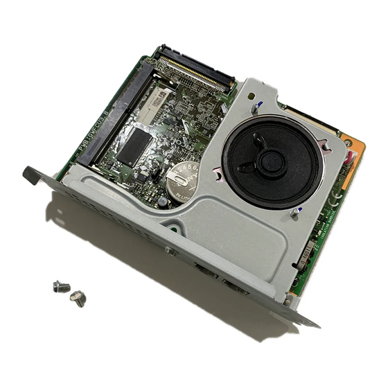
5. Detailed Section Descriptions Overview The FCU, which is composed of one PCB, controls all the fax communications and fax features, in cooperation with the controller board. Fax Options: • Extra G3 Interface option: This provides one more analog line interface. This allows full dual access. -
Page 200: Boards
5. Detailed Section Descriptions Boards The FCU (Facsimile Control Unit) controls fax communications, the video interface to the base copier’s engine, and all the fax options. FACE3.5 (Fax Application Control Engine) • CPU • Data compression and reconstruction (DCR) • DMA control •... -
Page 201: Sg3 Board
Boards • The SAF memory is backed up by a rechargeable battery. • 4MB flash ROMs for system software storage SRAM • The 512 KB SRAM for system and user parameter storage is backed up by a lithium battery. Memory Back-up •... - Page 202 5. Detailed Section Descriptions The SG3 board allows up to three simultaneous communications when used in combination with the FCU and optional G3 boards. The NCU is on the same board as the common SG-3 board. This makes the total board structure smaller. But, the specifications of the SG3 board do not change. NCCP (New Communication Control Processor) •...
-
Page 203: Video Data Path
Video Data Path Video Data Path Transmission Memory Transmission and Parallel Memory Transmission The base copier's scanner scans the original at the selected resolution in inch format. The IPU processes the data and transfers it to the FCU. • When scanning a fax original, the IPU uses the MTF, independent dot erase and thresholding parameter settings programmed in the fax unit’s scanner bit switches, not the copier's SP modes. -
Page 204: Immediate Transmission
5. Detailed Section Descriptions Then, the FCU converts the data to mm format, and compresses the data in MMR or raw format to store it in the SAF memory. If image rotation will be done, the image is rotated in page memory before compression. -
Page 205: Reception
Video Data Path Reception First, the FCU stores the incoming data from either an analog line to the SAF memory. (The data goes to the FACE3 at the same time, and is checked for error lines/frames.) The FCU then decompresses the data and transfers it to page memory. If image rotation will be done, the image is rotated in the page memory. -
Page 206: Fax Communication Features
5. Detailed Section Descriptions Fax Communication Features Multi-port When the optional extra G3 Interface Unit is installed, communication can take place at the same time through the two or three lines at once. Available protocol Option Available Line Type Combinations Standard only PSTN Extra G3 Interface Unit (single) -
Page 207: Internet Mail Communication
Fax Communication Features Then the controller stores the data in the page memory for the copier function, and compresses the data in MMR (by software) to store it in the HDD. If image rotation will be done, the image is rotated in the page memory before compression. - Page 208 Direct SMTP Transmission Internet Fax documents can be sent directly to their destinations without going through the SMTP server. (Internet Faxes normally transmit via the SMTP server.) For example: e-mail address: gts@ricoh.co.jp SMTP server address: gts.abcd.com...
-
Page 209: Mail Reception
Fax Communication Features In this case, this feature destination e-mail address (gts@ricoh.co.jp) is read as the SMTP server address "gts.abcd.com", and the transmissions bypass the SMTP server. This leads to decrease the server load and to reduce the time lag during transferring the mail. - Page 210 5. Detailed Section Descriptions • POP3 (Post Office Protocol Ver. 3.) • IMAP4 (Internet Messaging Access Protocol) • SMTP (Simple Mail Transfer Protocol) • For details: Core Technology Manual – Facsimile Processes – Faxing from a PC – Internet/LAN Fax Boards – Mail Reception POP3/IMAP4 Mail Reception Procedure The machine automatically picks up e-mail from the server at an interval which is adjustable in the range 2 to 1440 min.
-
Page 211: Handling Mail Reception Errors
In order to limit access to mail delivery with IFAX, the addresses of senders must be limited using the Access Limit Entry. Only one entry can be registered. 1. Access Limit Entry For example, to limit access to @IFAX.ricoh.co.jp: gts@IFAX.ricoh.co.jp Matches and is delivered. -
Page 212: Secure Internet Reception
5. Detailed Section Descriptions Header Supported Types Content-Type Multipart/mixed, text/plain, message/rfc822 Image/tiff US-ASCII, ISO 8859 X. Other types cannot be handled, and Charset some garbage may appear in the data. Content-Transfer- Base 64, 7-bit, 8-bit, Quoted Printable Encoding 2. MIME decoding errors 3. -
Page 213: E-Mail Options (Sub Tx Mode)
Fax Communication Features Field Content Multipart/mixed Content-Type Text/Plain (for a text part), image/tiff (for attached files) Content-Transfer-Encoding Base 64, 7-Bit, 8-bit, Quoted Printable RELAY-ID-: xxxx (xxxx: 4 digits for an ID code) Mail body (text part) RELAY: #01#*X#**01…. Message body MIME-converted TIFF-F. - Page 214 5. Detailed Section Descriptions Mail Type Item 1 Item 2 Item 3 1. "CSI" ("RTI") Normal: Return Receipt (dispatched). You can select 2. "RTI" CSI not registered Confirmation "displayed" with IFAX From of Reception SW02 Bits 2 and 3. 3. "CSI" RTI not registered Error: Return Receipt...
- Page 215 Fax Communication Features An e-mail message (up to 5 lines) can be pre-registered with: User Tools> System Settings> File Transfer> Program/Change/Delete E-mail Message - Limitations on Entries - Item Maximum Number of Lines 5 lines Line Length 80 characters Name Length 20 characters Message Disposition Notification (MDN) For details: Core Technology Manual –...
- Page 216 5. Detailed Section Descriptions After the mail sender transmits a request for a return receipt, the mail sender's journal is annotated with two hyphens (--) in the Result column and a "Q" in the Mode column. - Mail Receipt (Request for Receipt Confirmation) and Sending Mail Receipt Response - After the mail receiver sends a response to the request for a return receipt, the mail receiver's journal is annotated with two hyphens (--) in the Result column and an "A"...
-
Page 217: Ip-Fax
IP-Fax IP-Fax What is IP-FAX? For details: Core Technology Manual – Facsimile Processes – Faxing from a PC – Internet/LAN Fax Boards – IP-FAX T.38 Packet Format TCP is selected by default for this machine, but you can change this to UDP with IPFAX SW 00 Bit 1. UDP Related Switches IP-Fax Switch 01 Function... - Page 218 5. Detailed Section Descriptions...
-
Page 219: Specifications
6. Specifications General Specifications Type: Desktop type transceiver PSTN (max. 3ch.) Circuit: PABX Connection: Direct couple Book (Face down) Maximum Length: 432 mm [17 ins] Maximum Width: 297 mm [11.7 ins] ARDF (Face up) (Single-sided document) Original Size: Length: 128 - 1200 mm [5.0 - 47.2 ins] Width: 105 - 297 mm [4.1 - 11.7 inch] (Double-sided document) Length: 128 - 432 mm [5.0 - 17 inch]... - Page 220 6. Specifications G3: 3 s at 28800 bps; Measured with G3 ECM using memory for an Transmission Time: ITU-T #1 test document (Slerexe letter) at standard resolution Data Compression: MH, MR, MMR, JBIG Protocol: Group 3 with ECM V.34, V.33, V.17 (TCM), V.29 (QAM), Modulation: V.27ter (PHM), V.8, V.21 (FSK) G3: 33600/31200/28800/26400/24000/21600/...
-
Page 221: Capabilities Of Programmable Items
Capabilities of Programmable Items Capabilities of Programmable Items The following table shows the capabilities of each programmable items. Item Standard Quick Dial 2000 Groups Destination per Group Destinations dialed from the ten-key pad overall Programs Auto Document Communication records for Journal stored in the memory Specific Senders The following table shows how the capabilities of the document memory will change after the Expansion Memory are installed. -
Page 222: Ifax Specifications
6. Specifications IFAX Specifications Local area network Ethernet 100base-Tx/10base-T Connectivity: Gigabit Ethernet 1000 Base-T IEEE802.11a/g, g (wireless LAN), 200 × 100 dpi (Standard resolution), 200 × 200 dpi (Detail resolution), 200 × 400 dpi (Fine resolution)*1, 400 × 400 dpi (Super Fine resolution)*1 Resolution: •... - Page 223 IFAX Specifications 1000 Mbps (1000 Base-T) Data Rate: 100 Mbps (100base-Tx) 10 Mbps (10base-T) SMTP-AUTH Authentication POP before SMTP Method: A-POP Remark: The machine must be set up as an e-mail client before installation. Any client PCs connected to the machine through a LAN must also be e-mail clients, or some features will not work (e.g.
-
Page 224: Ip-Fax Specifications
6. Specifications IP-FAX Specifications Local Area Network Ethernet/10base-T, 100base-TX Network: Gigabit Ethernet/1000 Base-T IEEE802.11a/b/g/n (wireless LAN) 8 x 3.85 lines/mm, 200x100 dpi (standard character), 8 x 7.7 lines/mm, 200x200 dpi (detail character), Scan line density: 8 x 15.4 lines/mm (fine character: optional expansion memory required), 16 x 15.4 lines/mm, 400x400 dpi (super fine character: optional expansion memory required) A3 or 11"... -
Page 225: Fax Unit Configuration
Fax Unit Configuration Fax Unit Configuration G3 Interface Unit Type M12 Component Code Remarks D3A5-01, -02, -03, -11, -12 SG3 Board Optional D3A5-05, -06, SG3 Board Optional -07, -13 CCU I/F Board Included with optional G3 unit Expansion Memory D3A5-10... - Page 226 MEMO...