Sign In
Upload
Manuals
Brands
Viavi Manuals
Test Equipment
T-BERD/MTS 4000 V2
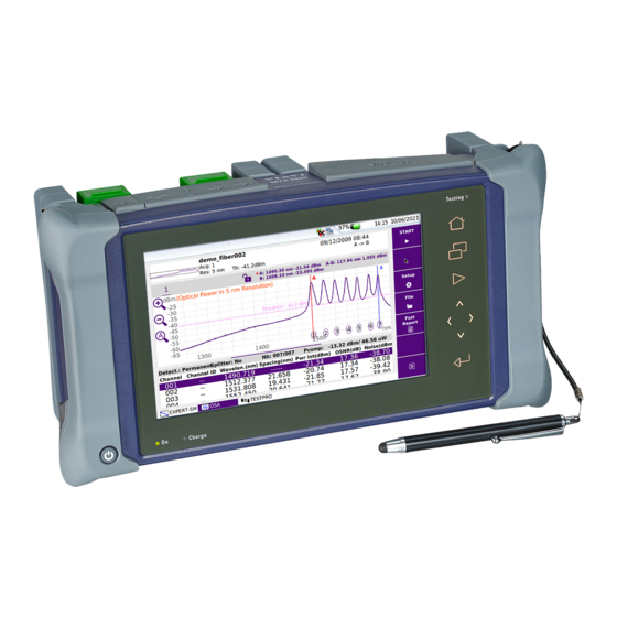
Viavi T-BERD/MTS 4000 V2 Test Platform Manuals
Manuals and User Guides for Viavi T-BERD/MTS 4000 V2 Test Platform. We have
3
Viavi T-BERD/MTS 4000 V2 Test Platform manuals available for free PDF download: User Manual, Manual, Quick Card
Viavi T-BERD/MTS 4000 V2 User Manual (280 pages)
OTDR Functions, Options and Software Applications
Brand:
Viavi
| Category:
Test Equipment
| Size: 28 MB
Table of Contents
Table of Contents
7
About this Guide
17
Assumptions
18
Conventions
18
Purpose and Scope
18
Recycling Information
18
Technical Assistance
18
Chapter 1 Principle of Measurement
21
Principle of Reflectometry Measurements
22
Information Yielded by the Measurement
22
Validity of Measurement ITU-T
23
Reflectance
23
Principle of Optical Power and Attenuation Measurements
24
Power Measurements
24
Attenuation Measurements (Optical Link Loss)
24
Chapter 2 Starting up
27
Unpacking the Device - Precautions
28
Fitting and Removing a Module (Not Available with Smartotdr)
28
Fitting a Module
28
Removing a Module
30
Connecting Fiber Optic Cable
30
Inspecting and Cleaning Connector End Faces
30
Optical Connector Types
31
Connecting Fiber Optic Cable to Test Port
32
Optical Connectors and Interchangeable Adapters
33
Interchangeable Adapters
33
Switchable Adapters
33
Cleaning Universal Connectors
35
Chapter 3 Activating OTDR Function
37
Selecting the Smart Test
38
Principle of the Smart Test
38
Selecting Smart Test
38
Selecting the OTDR Expert Function
39
Principle of the OTDR Expert
39
Selecting OTDR Expert
39
Configuring the Reflectometry Test
41
Configuring the Unit for Smart Test
42
Selecting the Configuration File
42
Chapter 4 Configuring the Reflectometry Test
42
Modifying some Parameters before the Acquisition
43
Configuring the Test in Expert OTDR
45
Configuring the Acquisition Parameters
46
Parameters
46
Launch Cable Parameters
48
Specific Acquisition Parameters with DWDM Modules
50
Configuring the Alarms Parameters
51
Configuring the Analysis Parameters
53
Parameters
54
Measurement
57
Configuring the Link Parameters
59
Configuring the File Parameters
64
Configuration in Test Auto Mode
68
Saving OTDR Configuration in a File
69
Loading an Existing OTDR Configuration
70
Chapter 5 Launching a Reflectometry Test and Displaying Results
74
Performing OTDR Acquisitions
74
Performing an Acquisition in Real Time Mode
74
Principle of the Real Time Mode
74
Performing Acquisition in Real Time
74
Stopping the Real Time Acquisition
76
Performing a Measurement with Smart Test
76
Performing an Acquisition with Expert OTDR
77
Performing an Acquisition from Results Page
79
Multi-Wavelength Acquisition
79
Actions on Trace During Acquisition
80
Saving Results for Smart Test Acquisitions
82
Results Display
84
Smart Link View
84
Show the Detailed Information of One Event
85
Event View
86
Trace View
89
Common Functions on Trace View
90
Advanced Functions in Expert OTDR Mode
100
Automatic Measurement and Detection
100
Addition of Events
101
Representation of the Events
101
Hints on the Positioning of Markers
102
Deleting Events
102
Manual Measurements
102
Measurements of Slope
102
Measurement of ORL
104
Measurement of Reflectance
104
Splice Measurements
105
Memorization of the Position of Events
107
Overlay Trace Function
108
Overlaying Several Traces Stored in Memory
108
Display of Traces in Overlay
108
Adding Traces in Overlay
109
Swapping Overlay Traces
109
Removing a Trace
110
Quitting the Overlay Menu
110
Reference Trace Function
110
Use of the Reference Trace Function in the Result Page
110
Using the Reference Trace Function in the Explorer
111
Saving the Trace(S) and Generating a Report
112
Saving Results and Creating a Report from Results Page
112
Opening a Report
114
Optipulses™ Option
115
Configuring the OTDR Acquisition with Optipulses™ Mode
116
Results in Optipulses™ Mode
117
Modules
119
Chapter 6 Power Meter and Source Options of the OTDR
120
Connection to the Power Meter
120
Configuring the Power Meter
120
Configuring the Alarm Parameters
121
Configuring the Measurement Parameters
122
Activating the Source Function
123
Result Page
123
Result Page of the Power Meter
123
Table of Results
124
Commands of the Power Meter Parameters
124
Combo PM/OTDR
125
Result Page of the Source
126
Performing the Power Level Measurement
127
Performing the Insertion Loss Measurement
128
Setting the Zero Value of the Power Meter
128
Carrying out the Reference
128
Carrying out the Side by Side Reference
128
Carrying out the Reference in Loopback Mode
130
Measurements on the Fiber under Test
131
Storing and Reloading Results
132
File Setup
132
Storing Results
133
Loading Results
133
Terminated PON Powermeter (Smartotdr Only)
133
Configuring the Powermeter
134
Configuring the Alarm Parameters
135
Configuring the Measurement Parameters
135
Configuring the Link Parameters
135
Setting the Zero Value of the Power Meter
137
Measuring the Signals
137
Combo PM/OTDR
138
Storing Results
139
Chapter 7 FTTA-SLM Software Option
141
Principle of FTTA-SLM
142
Acceptance Testing
142
Troubleshooting Testing
143
Configuring the Reflectometry Test for FTTA Network
144
Acquisition (FTTA)
145
Alarms
146
Analysis
147
Link
148
Launching the Acquisition
150
Results Page
151
Trace View
151
Smartlink View
153
Getting a Diagnostic of an Event
154
Event View
155
Changing the Name of an Event
156
Saving the Trace(S) and Generating a Report
157
Saving Results and Creating a Report from Results Page
157
Opening a Report
159
Chapter 8 FTTH-SLM Software Option
161
Principle of FTTH
162
Configuring the Reflectometry Test for FTTH Network
163
FTTH Setup
163
Acquisition
163
Alarms Parameters
167
Link Parameters
168
Launching the Acquisition
169
Results Page
170
Trace View
170
Smartlink View
172
Getting a Diagnostic of an Event
173
Results Table
174
Event View
174
Changing the Type of an Event
175
Saving the Trace(S) and Generating a Report
177
Saving Results and Creating a Report from Results Page
177
Opening a Report
178
Chapter 9 Cable-SLM Option
181
Principle of Cable-SLM
182
Configuring the Cable-SLM Project
182
Configuring the Project
182
Saving the Project
183
Loading an Existing Project
184
Starting Project Test Process
185
Trace Saving
186
Results of Project Cable
186
Description of the Table
186
Deactivate the Fiber Test
187
View Trace
187
Files and Project Storage
188
Text File Content
190
Chapter 10 Enterprise-SLM Software Option
191
Enterprise-SLM Software Option Principle of Enterprise-SLM
192
Configuring the Enterprise-SLM
192
Loading a Smartconfig
192
Acquisition
193
Alarms
194
Site Info Labels
194
Site Properties
195
Labeling
195
File
198
Simple OTDR Testing (for Single Fiber)
199
Managing Projects for Multi-Fibers Testing
199
Opening an Existing Project
199
Creating a Project from the Setup Page
200
Project Display
201
Testing MPO
202
Stopping the Test
203
Trace Saving
203
Results of Project
203
Description of the Table
204
View Trace
204
Smartlink View
206
Saving the Trace(S) and Generating a Report
207
Chapter 11 Fibercomplete Modules
211
Fibercomplete Modules General Introduction
212
Principle
212
Configurations
213
Activating the Function
215
Establishing References
215
Reference Stage Process
216
Loopback Referencing Method
217
Side-By-Side Referencing Method
218
Factory References
219
Configuring the Units
220
Acquisition Parameters
221
Alarms Parameters
223
Analysis Parameters
223
File Parameters
224
Automatic Configuration
225
Saving the Parameters from Fibercomplete Configuration
226
Loading a Configuration File Fibercomplete
227
Performing the Tests
227
Sending a Message to the Distant Platform
228
Starting the Test
229
Results Screen
230
Cable View
230
Fiber View
231
Fault Finder
231
Otdr
232
Saving Results and Generating a Report
233
Saving Results and Creating a Report from Results Page
233
Opening a Report
235
File Management
236
Storing Results
236
Filenaming Convention
236
File Management
239
Chapter 12 File Management
239
Description of the Explorer
240
Opening the File Explorer
240
Managing Tabs
240
File Signature
241
Buttons on the Right of the Screen
242
Storage Media
242
Directories and Files Editing Function
242
Saving and Loading Files
243
Saving Files from the Explorer
243
Loading Files and Displaying Traces
244
Simple Loading
244
Load with Configuration
244
Loading Several Traces in Overlay
245
Exporting Files
245
Explorer/Link Manager
245
Editing Function
247
Exporting a Directory in a Txt File
247
Generating Pdf Report(S)
248
Using the Merge Key, with the Txt/Pdf Files
249
Chapter 13 Technical Specifications
251
OTDR Modules for T-BERD/MTS 2000/4000 V2
252
Characteristics of Reflectometry Measurements
252
Manual Measurement
253
Typical Specifications
253
CWDM Modules
255
DWDM Modules
256
Ranges
256
Class of the Lasers of the OTDR Modules
259
OTDR Modules Measurement
259
Technical Specifications of the Power Meter Function on OTDR Module
259
Technical Specifications of the Source Function on OTDR Module for T-BERD/MTS-2000/4000 V2
261
Technical Specifications of the Fibercomplete Modules
261
MPO Switch Module Technical Specifications
262
OTDR Technical Specifications for Smartotdr
263
OTDR Optical Interfaces
263
OTDR Optical Characteristics
263
Characteristics of Reflectometry Measurements
263
Typical Specifications
264
Characteristics of the Source (Standard) and Power Meter (Optional)
265
Source
265
Power Meter (through OTDR Port)
266
PON/XG-PON Power Meter (E118FA65PPM Version)
266
Chapter 14 Options and Accessories
267
References of Measurement Modules for T-BERD/MTS-2000/4000 V2
268
OTDR Modules
268
CWDM OTDR Modules
269
DWDM OTDR Modules
270
MPO Switch Module
270
Fibercomplete Modules with OTDR Function
270
Fibercomplete Modules with Fault Finder Function
271
Options
271
References of the Smartotdr
272
User Manual References
272
References of Optical Connectors and Adapters
273
Index
275
Advertisement
Viavi T-BERD/MTS 4000 V2 Manual (212 pages)
Optical Test Platform
Brand:
Viavi
| Category:
Test Equipment
| Size: 16 MB
Table of Contents
Table of Contents
9
About this Guide
19
Assumptions
20
Purpose and Scope
20
Recycling Information
20
Technical Assistance
20
Conventions
21
Chapter 1 Safety Information
24
AC/DC and Battery Important Safety Instructions
24
Precautions Relating to Optical Connections
25
Laser Safety
25
Laser Classes
25
Warning Labels for the Laser Classes
26
Chapter 2 4000 V2 Platform Overview
27
Unpacking the Instrument
28
About the 4000 V2 Platform
28
Main Features
29
Hard Keys and Indicators
31
Front Panel Tactile and Hard Keys
31
Front Panel Indicators
32
Power Supply
32
Starting up
35
Fitting and Removing a Module
36
Fitting a Module
36
Removing a Module
37
Setting the 4000 V2 Platform into the Glove
37
Charging the Battery
38
Connecting the Mains Adapter
38
First Use of the Battery
38
Charging
39
Battery Charge Level Display
39
Switching the 4000 V2 Platform on and off
40
Switching on the 4000 V2 Platform
40
Switching off the 4000 V2 Platform
40
Resetting the 4000 V2 Platform
41
First Start: Configuring Your Regional Settings
41
Configuring the 4000 V2 Platform
43
Displaying the System Settings Screen
44
Defining the Screen Parameters of the 4000 V2 Platform
45
Backlight
45
Contrast
45
Screen Saver
46
Defining the "Utility" Parameters
46
Defining the Automatic Shutdown of the 4000 V2 Platform
46
Defining the Storage Limit
46
Power Meter, VFL (Visual Fault Locator) & Talkset
47
Connection to the Power Meter, VFL and Talkset
48
Configuring the Power Meter
48
Configuring the Measurement Parameters
48
Configuring the Alarm Parameters
50
Configuring the Link Description Parameters
50
Configuring the Report Parameters
52
Activating the Source Function
55
LTS Results Page
55
Result Page of the Power Meter
55
Table of Results
55
Keys of the Power Meter
56
Combo PM/OTDR
57
Performing a Power Level Measurement
57
Performing an Insertion Loss Measurement
57
Setting the Zero Value of the Power Meter
57
Performing a Reference
58
Measurements on the Fiber under Test
59
Storing and Reloading Results
60
Report Setup
60
Storing Results
60
Loading Results
60
VFL Function
61
VFL Connector
61
Visual Fault Locator Function (VFL)
61
Talkset and Datalink Functions
62
Talkset Configuration
63
Connections
63
Establishing Communication
64
Remote Screen Function Via Optical Datalink
65
Establishing Communication
65
Adjusting Volume Level
65
End of a VNC Session
66
Disconnection
66
Scope
67
Scope Feature
68
Overview
68
Installation of Tips
69
Configuring the Scope
69
P5000I Scope Connection
69
Fiberchek Scope Connection
70
WIFI Connection
70
USB Connection
71
Configuring the Scope
71
Analysis
72
Link
73
File
74
Managing Scope Profiles
77
Defining the Profiles Available on the Setup Screen
77
Importing a Profile to the Scope Application
78
About Page
78
Starting up with the Scope
79
Freeze Mode
80
High Mag. / Low Mag
80
Live Mode
80
Launching a Test of the Connector and Fiber End-Face
81
Mosaic Mode
82
Loading a Picture
84
File Menu
85
Saving the Test Result in a Jpg File and / or in a Report
85
Display of the Report
85
Connectivity
87
Establishing Connection
88
Via Bluetooth
88
Pairing the Platform with a Device
88
Searching New Devices to be Paired with the Platform
90
Removing the Pairing
91
Via Wifi
91
Configuring the WIFI Access
91
Connection to SSID
93
Configuring the WIFI Mode to Which the Platform Is Connected
93
Creating a Network from the 4000 V2 Platform
94
Via Ethernet
95
Connecting the 4000 V2 Platform and the PC
95
Configuring the 4000 V2 Platform Via Ethernet
96
Via Cloud Storage
98
Principle and Prerequisites of the Cloud Storage
98
Form
98
Remote Control
100
Smart Access Anywhere
100
Connection Modes
100
Pre-Requisite for Using the Smart Access Anywhere Application
103
Downloading the VIAVI Application on PC
103
Downloading the VIAVI Application on Tablet/Smartphone
104
Launching the Smartaccess Anywhere Application
105
Using Remote Screen and File Transfer Applications
107
Working with Files and Directories on 4000 V2 Platform
111
Connection Information and Settings
111
M2M Link Option
114
Data Transfer
117
Transferring Files Via Bluetooth
117
Transferring Files To/From a PC Via WIFI or Ethernet
118
Transferring Files Using Cloud Storage
119
Vnc
120
Transferring the Interface on a PC Via WIFI or Ethernet
121
Virtual Control Buttons Bar
122
Equivalence between the Keyboard and 4000 V2 Platform
123
Stratasync
124
Principle and Prerequisites of the Stratasync
124
Configuring and Synchronizing the 4000 V2 Platform
125
Connecting the 4000 V2 Platform to Stratasync
126
GPS Option
126
Applications
131
PDF Reader
132
Interacting with a PDF Document
132
Text Editor
133
Text Editor Page
133
Saving the Text in a File
133
Calculator
134
File Explorer
135
Chapter 9 Job Manager Option
138
Principle of the Job Manager
138
Creating a Test Plan and Loading It on the Platform
139
Pre-Requisites
139
Creating a Test Plan
139
Job Information
140
Configuring the Test Plan
140
Adding the Multiple Tests Plan to Job Manager
151
Saving the Job Manager File and Loading It on Platform
153
Loading the Json File on the Platform Job Manager
153
Modifying the Job Information from Platform
155
Performing Tests and Generating Reports
156
Launching the Test from Test Plan
156
Tests Results in Job Manager
158
Displaying the Test Reports
159
Other Functions on Job Manager Screen
159
Summary Report
159
Synchronization with Stratasync
160
File Management
161
File Explorer Overview
162
Directories and Files Selections
162
Directory Selection
162
Files Selection
163
Directories & Files Editing Functions
163
Copy/Cut & Paste Files/Directories
163
Renaming a Directory / File
164
Deleting a Directory / File
164
Working with Directories / Files from the Explorer
165
Creating a Directory
165
Opening Files
165
File Types
165
Creating a Screenshot
166
Taking a Screenshot
166
Name of the Screenshots Files
167
Merging Pdf or Txt Files
167
Storage Media
168
Storage Media Built into the 4000 V2 Platform
169
External USB Storage Media
169
USB Memory Stick Connection
169
USB Memory Stick Disconnection
169
Abbreviations for Storage Media
170
Technical Specifications
171
Display
172
Indoor/Outdoor
172
Memory
172
Input/Output
172
Power Supply
173
Battery
173
Mains Adapters
174
Dimensions - Weight
174
Environment
175
Temperature
175
Humidity
175
Pollution Degree
175
Emi/Esd
176
Overvoltage
176
Drop Test
176
Shocks
176
Bumps
176
Vibration
176
Flammability
177
IP Protection Index
177
Characteristics of the Options
177
Power Meter Option
177
Talkset Option
178
VFL Option
178
WIFI and Bluetooth Options
178
Chapter 12 Options and Accessories
179
References of Options for the 4000 V2 Platform Mainframe
180
Reference of Scope
183
References of Accessories
183
References of Manuals
183
References of Result Processing Software
184
Maintenance & Troubleshooting
185
Cleaning
186
Cleaning Plates and Housings
186
Cleaning the Screen
186
Cleaning the Optical Cable Connector
187
Cleaning the Optical Connections of the 4000 V2 Platform
187
Accessing to the 4000 V2 Platform Information
187
General Page
187
Software Options Page
188
Services Data Page
189
Accessing to the 4000 V2 Platform Documentation
189
Installing a New Version of the Software
190
Downloading from Internet
190
Installation from VIAVI Server
191
Installation from Another Server
192
Installation from a USB Memory Stick
193
Launching the Upgrade
194
Checking New Upgrade on VIAVI Server
195
Install Software License
195
Install Options from VIAVI Server
196
Enter Manually the License
197
Import the License from the USB Memory Stick
198
Locking the 4000 V2 Platform
199
Returning an Instrument
201
Guarantee Conditions
201
Recycling Information
201
Troubleshooting
202
Interpreting Alarms
202
Formatting the USB Memory Stick Onto the 4000 V2 Platform
203
Erase Disk
203
Changing the Battery
203
Accessing to the Damaged Battery
204
Installing a New Battery
204
General Information on Warranty
205
Hardware Warranty
205
Warranty Disclaimer
206
Viavi T-BERD/MTS 4000 V2 Quick Card (3 pages)
Modular Test Set Real Time Testing with Expert OTDR
Brand:
Viavi
| Category:
Test Equipment
| Size: 0 MB
Table of Contents
Equipment Requirements
1
Fiber Inspection Guidelines
1
Connect Launch Cable to OTDR Port
1
Connect to Fiber under Test (FUT)
2
Launch and Configure Expert OTDR
2
Run Test
3
Advertisement
Advertisement
Related Products
Viavi T-BERD/MTS 2000
Viavi T-BERD/MTS-4000 v2
Viavi T-BERD/MTS 5800
Viavi T-BERD/MTS 5800-100G
Viavi T-BERD MTS 5800-100G
Viavi T-BERD 4000 Base Unit
Viavi OTDR 41 MA2 Series
Viavi OTDR 41 MA3 Series
Viavi T-BERD/MTS-5800V2
Viavi T-BERD MTS 5800
Viavi Categories
Test Equipment
Measuring Instruments
Microscope
Control Unit
Server
More Viavi Manuals
Login
Sign In
OR
Sign in with Facebook
Sign in with Google
Upload manual
Upload from disk
Upload from URL