
Related Manuals for Viavi 4000 V2


Summary of Contents for Viavi 4000 V2
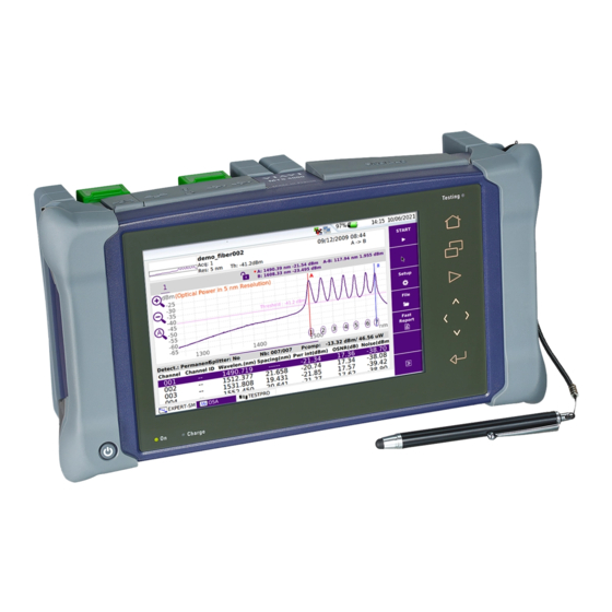
- Page 1 4000 V2 Optical Test Platform Modular Test Platform designed for the installation, turn-up and maintenance of fiber optic networks User Manual...
- Page 3 4000 V2 Optical Test Platform Modular Test Platform designed for the installation, turn-up and maintenance of fiber optic networks User Manual Viavi Solutions 1-844-GO-VIAVI www.viavisolutions.com...
- Page 5 Trademarks VIAVI and 4000 V2 Platform are trademarks or registered trademarks of VIAVI in the United States and/or other countries. Microsoft, Windows, Windows CE, Windows NT, and Microsoft Internet Explorer are either trademarks or registered trademarks of Microsoft Corporation in the United States and/or other countries.
- Page 6 For the VIAVI position statement on the use of Proposition 65 chemicals in VIAVI prod- ucts, see the Hazardous Substance Control section of VIAVI's Standards and Policies web page.
- Page 7 Substances of Very High Concern (SVHC) is present in an article above a certain threshold. For information on the presence of REACH SVHCs in VIAVI products, see the Hazardous Substance Control section of VIAVI's Standards and Policies web page.
- Page 8 viii User Manual 74000NG012 Rev. 004...
-
Page 9: Table Of Contents
........6 About the 4000 V2 Platform . - Page 10 ......22 Defining the screen parameters of the 4000 V2 Platform ..23 .
- Page 11 Contents Activating the Source function ........33 LTS Results page .
- Page 12 Connection to SSID ........71 Configuring the WIFI mode to which the Platform is connected . 71 Creating a network from the 4000 V2 Platform ....72 User Manual...
- Page 13 Pre-requisite for using the Smart Access Anywhere Application . 81 Downloading the VIAVI application on PC ....81 Downloading the VIAVI application on Tablet/Smartphone ..82 Launching the SmartAccess Anywhere application.
- Page 14 Contents ..........111 Text Editor page .
- Page 15 ....147 Storage media built into the 4000 V2 Platform ........147 External USB storage media USB memory stick connection .
- Page 16 Downloading from Internet ....... 168 Installation from VIAVI Server ......169 Installation from another server .
- Page 17 Install Software License Install options from VIAVI Server ......174 Enter Manually the License ....... . 175 Import the license from the USB memory stick .
- Page 18 Contents xviii User Manual 74000NG012 Rev. 004...
-
Page 19: About This Guide
About This Guide The 4000 V2 Platform of VIAVI provides a portable, modular platform designed for the installation, turn-up and maintenance of fiber optic networks. The topics discussed in this chapter are as follows: • “Purpose and scope” on page xx •... -
Page 20: Purpose And Scope
Purpose and scope Purpose and scope The purpose of this guide is to help you successfully use the 4000 V2 Platform features and capabilities. This guide includes task-based instructions that describe how to install, configure, use, and troubleshoot the 4000 V2 Platform. -
Page 21: Conventions
About This Guide Conventions Conventions This guide uses naming conventions and symbols, as described in the following tables. Table 1 Typographical conventions Description Example User interface actions appear in this On the Status bar, click Start. typeface. Buttons or switches that you press on a Press the switch unit appear in this... - Page 22 About This Guide Conventions Table 3 Symbol conventions This symbol represents a general hazard. This symbol represents a risk of electrical shock. NOTE This symbol represents a Note indicating related information or tip. This symbol, located on the equipment or its packaging indicates that the equipment must not be disposed of in a land-fill site or as munici- pal waste, and should be disposed of according to your national regu- lations.
- Page 23 Safety information Chapter 1 This chapter gives the main information on the safety conditions when using the 4000 V2 Platform • “AC/DC and battery important safety instructions” on page 2 • “Precautions relating to optical connections” on page 3 • “Laser safety”...
-
Page 24: Chapter 1 Safety Information
• Batteries supplied by VIAVI incorporate protection means. If another adapter or battery is used, it may damage the 4000 V2 Platform itself. Using the product with batteries other than those supplied by the manufacturer of the 4000 V2 Platform may entail risks of fire or explosion. -
Page 25: Precautions Relating To Optical Connections
• The optical connectors must therefore be clean and dust-free. If the optical connection is not being used, protect the connections of 4000 V2 Platform using the protective caps. As an example, the results of measurements made with connectors that have not been cleaned will display an error of the order of 10% for all measurements. -
Page 26: Warning Labels For The Laser Classes
Chapter 1 Safety information Laser safety • VFL option: Class 2 Warning labels for the laser classes Due to the reduced dimensions of the optical modules, it is not possible to attach the required warning labels to them. In line with the provisions of Article 7.1 of the IEC 60825-1:2014 standard, the laser class identification labels are shown below: Reference standard IEC 60825-1:2014... -
Page 27: Chapter 2 4000 V2 Platform Overview
4000 V2 Platform Overview Chapter 2 This chapter provides a general description of the 4000 V2 Platform. Topics discussed in this chapter include the following: • “Unpacking the instrument” on page 6 • “About the 4000 V2 Platform” on page 6 •... -
Page 28: Unpacking The Instrument
About the 4000 V2 Platform The architecture of the 4000 V2 Platform is made of one Platform, to which one or two modules can be added to perform tests on fiber networks. The modules that can be fitted to the 4000 V2 Platform are interchangeable in the field and different kinds of module are usable: •... -
Page 29: Main Features
Open all user documentations included into the 4000 V2 Platform • Update the 4000 V2 Platform firmware • Remote the screen of the 4000 V2 Platform onto a PC and issue commands from the keyboard of the PC • Fig. 1... - Page 30 Chapter 2 4000 V2 Platform Overview Main features Fig. 2 4000 V2 Platform: Front view TFT 9’’ Color Indicators Touchscreen Tactile keys Hard key Indicators Fig. 3 4000 V2 Platform: Connectors View Talkset USB host RJ45 AC/DC Input User Manual...
-
Page 31: Hard Keys And Indicators
Chapter 2 4000 V2 Platform Overview Hard keys and Indicators Hard keys and Indicators Front panel tactile and hard keys Hard key Function Main on/off switch Tactile keys The Home tactile key gives access to: • selection of the different measurement or functions •... -
Page 32: Front Panel Indicators
It is saved in the directory Report, created automatically at screenshot generation. Figure 4 Buttons on the upper banner Front panel indicators The 4000 V2 Platform is equipped with three indicators, lit into a different color according to the status of the unit. Table 2 Indicators Status On indicator... - Page 33 Chapter 2 4000 V2 Platform Overview Power Supply • the Li-Polymer battery, already set into the equipment on delivery. • an AC adapter/charger, via a power cable on which has been set the correct country adaptable plug. Fig. 5 4000 V2 Platform power supply User Manual 74000NG012 Rev.
- Page 34 Chapter 2 4000 V2 Platform Overview Power Supply User Manual 74000NG012 Rev. 004...
-
Page 35: Starting Up
Starting up Chapter 3 This chapter explains the operations to be carried out before using the 4000 V2 Platform. The topics discussed in this chapter are as follows: • “Fitting and removing a module” on page 14 • “Setting the 4000 V2 Platform into the glove” on page 15 •... -
Page 36: Fitting And Removing A Module
Chapter 3 Starting up Fitting and removing a module Fitting and removing a module The 4000 V2 Platform must be switched off, and if it is operating on the mains, its supply cable must be unplugged. Fitting a module •... -
Page 37: Removing A Module
This glove has been designed to fit to the equipment, and to easily get access to all the commands of the product (interface, modules, connectors). To set the 4000 V2 Platform in the glove, take care of the sense of insertion: the screen must face the front of the glove. Refer to Figure Once in the glove, the 4000 V2 Platform can be set to the «standing»... -
Page 38: Charging The Battery
4000 V2 Platform. At the top of the 4000 V2 Platform, lift up the power supply socket protector and plug in the mains adapter. -
Page 39: Charging
Chapter 3 Starting up Charging the battery Charging If the instrument is fitted with a battery, on connection to the mains: • if the user does not press , the battery will start the charge. In this case, the Charge indicator will be lit in red. •... -
Page 40: Switching The 4000 V2 Platform On And Off
Switching the 4000 V2 Platform on and off The mains adapter is used not only for charging the battery (if the battery is installed), but also for operating the 4000 V2 Platform on the mains, if a mains socket is at hand, to save the battery. -
Page 41: Resetting The 4000 V2 Platform
First start: configuring your regional settings Once the 4000 V2 Platform is switched on, the first screen displayed allows to configure the regional settings. Those settings will be kept in memory and automatically applied on the instrument each time it is restarted. - Page 42 Chapter 3 Starting up First start: configuring your regional settings Click on Date and enter the current date, using the numeric keypad displayed using the menu key Edit Number. Click on Time and enter the current time, using the numeric keyboard displayed using the menu key Edit Number.
-
Page 43: Configuring The 4000 V2 Platform
The topics discussed in this chapter are as follows: • “Displaying the System Settings screen” on page 22 • “Defining the screen parameters of the 4000 V2 Platform” on page 23 • “Defining the «Utility» parameters” on page 24 User Manual... -
Page 44: Displaying The System Settings Screen
Chapter 4 Configuring the 4000 V2 Platform Displaying the System Settings screen Displaying the System Settings screen To display the System Settings screen, you must: Press the H key to reach the Home page. Fig. 9 Home page Activate the Settings icon to open the System Settings screen. -
Page 45: Defining The Screen Parameters Of The 4000 V2 Platform
– Min backlight level: -5 – Max backlight level: +5 If the 4000 V2 Platform is operating on battery, it is advisable to choose a minimum lighting level, acceptable for the user, to keep endurance as long as possible. Contrast... -
Page 46: Screen Saver
Click on Screen Saver if you wish to activate a screen saver to the equipment, to extend the life of the battery, in case the 4000 V2 Platform is not used for some time. Instead of the normal screen, a small animated picture of the 4000 V2 Platform is displayed on the blackened screen. -
Page 47: Power Meter, Vfl (Visual Fault Locator) & Talkset
Power meter, VFL (Visual Fault Chapter 5 Locator) & Talkset A variety of built-in optical options are available when ordering. See references in Chapter 12 “Options and accessories”, for details. The topics discussed in this chapter are as follows: • “Connection to the power meter, VFL and Talkset”... -
Page 48: Connection To The Power Meter, Vfl And Talkset
Chapter 5 Power meter, VFL (Visual Fault Locator) & Talkset Connection to the power meter, VFL and Talkset Connection to the power meter, VFL and Talkset Fig. 12 Optical connectors Power meter / Talkset optical connection The type of optical connector used for the power meter is UPP (Universal Push Pull), which is compatible with all diameter 2.5 mm connectors (FC, SC, ST, DIN, E2000, etc.) Configuring the Power meter To activate the function:... - Page 49 Chapter 5 Power meter, VFL (Visual Fault Locator) & Talkset Configuring the Power meter Figure 13 Configuration of power measurement page 35 • Wavelength Select wavelength: Auto: the wavelength of the input signal will be automatically detected and selected to perform the measurement: 1310, 1490, 1550, 1625 or 1650 nm: measurement performed at specified wavelength.
-
Page 50: Configuring The Alarm Parameters
Chapter 5 Power meter, VFL (Visual Fault Locator) & Talkset Configuring the Power meter Configuring the alarm parameters Fig. 14 Configuration of power meter alarms • Alarm Activation of the Alarm function: any result below the lower threshold or above the upper threshold will be displayed in red on the Results page. - Page 51 Chapter 5 Power meter, VFL (Visual Fault Locator) & Talkset Configuring the Power meter The information entered in the Link Description window concerns the editing and/or the modifications of the cable and fiber parameters. When a trace is recalled without recall of the configuration, the parameters of this trace will be present only in its signature.
-
Page 52: Configuring The Report Parameters
Chapter 5 Power meter, VFL (Visual Fault Locator) & Talkset Configuring the Power meter Configuring the Report parameters The Report storage parameters must be also configured, in order to define how and where the results will be saved in the file system of the equipment. In the Setup menu, press Report. - Page 53 Chapter 5 Power meter, VFL (Visual Fault Locator) & Talkset Configuring the Power meter Figure 17 Directory - Onscreen keyboard Click on or leave the box empty to select the Current Directory for file saving. Press to validate. • This field displays the directory selected/created into which the file(s) will be saved.
- Page 54 Chapter 5 Power meter, VFL (Visual Fault Locator) & Talkset Configuring the Power meter Figure 18 Filenaming - Keyboard (auto) Click on to apply the name by default to the file: Fiber[Cable_Id][Fiber_Num]_[Lambda]_[Direction] The name of the file is displayed in grey under Filenaming parameter •...
-
Page 55: Activating The Source Function
The power level measured by the power meter and its measurement unit are displayed in large characters, together with: • the mode of transmission of the measured signal: continuous wave (CW) or modulated wave (available frequency 270Hz, 330Hz, 1KHz, or 2KHz, VIAVI Auto). • the wavelength of the measured signal. -
Page 56: Keys Of The Power Meter
Chapter 5 Power meter, VFL (Visual Fault Locator) & Talkset LTS Results page • A measurement result is displayed in the table when the Keep Result icon is pressed • The key deletes the values in the table. • If the Alarm function has been activated, any result that exceeds the setup thresholds appears in red in the table. -
Page 57: Combo Pm/Otdr
Chapter 5 Power meter, VFL (Visual Fault Locator) & Talkset Performing a power level measurement Combo PM/OTDR If the ExpertOTDR mode is activated at the same time as the Powermeter, a menu key Combo PM/OTDR function becomes available in the control bar. It allows to combine in the test report power levels and OTDR results. -
Page 58: Performing A Reference
Mainframe OTDR Source Power meter NOTE The reference can be performed with one 4000 V2 Platform at one side and one 2000 Platform at the other side. Before connecting fiber/jumper, use appropriate cleaning tool to clean connector end-faces. Connect the reference/graded jumper from the light source directly to the power meter. -
Page 59: Measurements On The Fiber Under Test
Chapter 5 Power meter, VFL (Visual Fault Locator) & Talkset Performing an insertion loss measurement The actual power level is set as the new reference level for the selected wavelength. Then, the displayed value is around 00.00 dB. The reference levels are stored and entered in the setup fields. Measurements on the fiber under test Once the references have been performed on both units: After a Side by side reference, always keep the jumper connected to the equipment (1) -
Page 60: Storing And Reloading Results
Chapter 5 Power meter, VFL (Visual Fault Locator) & Talkset Storing and reloading results Figure 22 Measurement of the Insertion Loss with a mode conditioner Fiber Under Test Mode Jumper Equipment (1) Equipment (2) conditioner OTDR Mainframe Multimode Power meter Source port port On equipment (1) select Laser START to activate the light source. -
Page 61: Vfl Function
Chapter 5 Power meter, VFL (Visual Fault Locator) & Talkset VFL Function VFL Function VFL connector The type of optical connector used for the VFL source is UPP (Universal Push Pull), which is compatible with all diameter 2.5 mm connectors (FC, SC, ST, DIN, E2000, etc.) Figure 12 on page 26 to visualize the VFL connector. -
Page 62: Talkset And Datalink Functions
To communicate along the fiber. • To transfer data along the fiber. Each end of the optical link must be provided with a 4000 V2 Platform equipped with the Talkset option. NOTE It is possible to use the Talkset of the 4000 V2 Platform and to carry out mea- surements at the same time, on a different fiber. -
Page 63: Talkset Configuration
“Adjusting volume level” on page Connections At each end of the fiber: Connect the fiber to the Talkset port of the 4000 V2 Platform, either directly or through jumpers. NOTE The Talkset option is delivered with a FC adapter mounted on standard on the talkset connector. -
Page 64: Establishing Communication
Data transfer varies according to the type of application you use. For Fiber Optics for example, you can use the explorer. The distant 4000 V2 Platform will be shown just like a disk and all file and directory features can be used from and to that disk. -
Page 65: Remote Screen Function Via Optical Datalink
Adjusting volume level The sound is transmitted to the earphones of the headset and, if this function has been activated, to the speaker in the 4000 V2 Platform. To activate the base loudspeaker and adjust the volume: Press the H key. -
Page 66: End Of A Vnc Session
VNC session or not. Disconnection When communication is over: Deactivate the Talkset/Datalink function on one of the 4000 V2 Platform. This deactivation can be done by either 4000 V2 Platform.Then, the fiber used can be disconnected safely. User Manual 74000NG012 Rev. 004... -
Page 67: Scope
Scope Chapter 6 The scope function is a hot-plug feature enabled directly when inserting a VIAVI scope supplied as an accessory (see Chapter 12 “Options and accessories”): The topics discussed in this chapter are as follows: • “Scope feature” on page 46 •... -
Page 68: Scope Feature
The P5000i and the FiberChek require an FBPT inspection tip. The P5000i is connected to the Platform 4000 V2 with a USB 2.0 connector. The FiberChek is connected to the Platform 4000 V2 with a mini-USB connector or via WIFI. -
Page 69: Installation Of Tips
Platform (see the FiberChek user manual). Installation of tips The Pass/Fail analysis function on the 4000 V2 Platform can only be used with certain inspection tips mounted on the P5000i. Seven tips, patchcords and bulkheads types, are delivered with the Videoscope Kit (ESDFSCOPE5Ki) but many others can be used. -
Page 70: Fiberchek Scope Connection
Turn on the scope. Make sure the WIFI connection is activated onto the Scope (see FiberChek User manual). On Platform 4000 V2, press the H button. Click on Connectivity > Wireless. Perform a scan to detect the Scope and establish the connection with the Plat- form (see “Configuring the WIFI access”... -
Page 71: Usb Connection
Chapter 6 Scope Configuring the Scope USB Connection Link the scope to the Platform 4000 V2 using a mini-USB cable. Fig. 28 WIFI connection of the FiberChek Scope to the Platform 4000 V2 Turn on the scope. On the Platform 4000 V2, press the H button. -
Page 72: Analysis
Chapter 6 Scope Configuring the Scope Figure 29 Scope Setup Analysis Profile On the line Profile, select the Profile which will be used for the test of fiber connector: • SM_UPC: Pass/Fail criteria for single-mode UPC connectors from IEC 61300-3- 35 standard. -
Page 73: Link
Chapter 6 Scope Configuring the Scope Capture button This parameter allows to select the action of the Quick Capture button onto the Scope (see Figure 25 on page 46): • Freeze & Test pressing the button will automatically perform a test of fiber and freeze the result •... -
Page 74: File
Chapter 6 Scope Configuring the Scope Increment; the fiber number is automatically incremented at each results saving Decrement: the fiber number is automatically decremented at each results saving. User Defined: Use the menu key Edit Number to enter the value for incrementa- tion / decrementation of the fiber number. - Page 75 Chapter 6 Scope Configuring the Scope File configuration Dir. Naming Click on Current Directory menu key to select the directory currently selected in the explorer for files saving Use the arrow to enter the directory name and path: In the edition keypad, select the pre-defined parameters available or, press abc key to enter a name manually for the directory.
- Page 76 Chapter 6 Scope Configuring the Scope In the edition keypad, select the pre-defined parameters available or, press abc key to enter a name manually for the file. Then, press Enter to validate. Fig. 31 Filenaming - Edition keypad (auto) Press Default Filename to apply the automatic name to the file: Fiber[Cable_Id][Fiber_Num]_[Direction] Below Filenaming, the name of the file is displayed.
-
Page 77: Managing Scope Profiles
Yes to generate a report in a pdf file • json file select Yes to generate json file(s) compatible with VIAVI test process automation (Job Manager and Stratasync cloud data management system) Managing scope profiles Once the Setup screen of the scope is displayed, you can : •... -
Page 78: Importing A Profile To The Scope Application
Chapter 6 Scope Configuring the Scope Figure 32 List of profiles available Importing a profile to the Scope application The profile must be created via FiberChekPro , and stored on one storage media of the 4000V2 Platform (disk, or USB memory stick). On the Setup screen, select Profile and press Manage. -
Page 79: Starting Up With The Scope
Chapter 6 Scope Starting up with the scope Figure 33 P5000i Scope: About page Information on scope used Information on active snapshot Starting up with the scope Once the Fiber Scope icon is validated: Press the Multi-views key and select Results. Figure 34 Example of the result using the P5000i scope Sharpness... -
Page 80: Freeze Mode
Chapter 6 Scope Starting up with the scope Freeze mode Once the image is acceptable, you may freeze the picture. This feature allows to store in memory the resulting picture. Freezing a scope result does not store the picture in a file (see “File menu”... -
Page 81: Launching A Test Of The Connector And Fiber End-Face
Chapter 6 Scope Launching a test of the connector and fiber end-face Launching a test of the connector and fiber end- face Launching a test of the connector and fiber end-face Once the display is correctly adjusted (magnification, sharpness...), a test of fiber connector can be launched. -
Page 82: Mosaic Mode
Chapter 6 Scope Launching a test of the connector and fiber end-face • Zone A: Core zone: it is the area surrounding the core Zone D • Zone B: Cladding zone. It surrounds the majority of the Zone C fiber cladding. Zone B •... - Page 83 Chapter 6 Scope Launching a test of the connector and fiber end-face Figure 36 Mosaic mode Selected picture Position 1: IVE CAMERA Position 2: File saved on disk • You may select one of the pictures by clicking on it. The selected picture is framed in green.
-
Page 84: Loading A Picture
Press the Multi-views key and select File. Press Explorer. Select the JPEG file to be loaded via the Explorer Click on Load Recognized pictures are images resulting from the Scope option and saved on disk via the 4000 V2 Base Unit. User Manual 74000NG012 Rev. 004... -
Page 85: File Menu
Chapter 6 Scope File menu Some pictures resulting from the Scope option may appear neverthe- less unrecognized, if they have been stored with a different Scope application, or if the JPG file has been opened and modified under another JPG editor. File menu Saving the test result in a jpg file and / or in a report Once the test has been performed, and the result is displayed on the 4000V2 Platform... - Page 86 Chapter 6 Scope File menu Figure 37 PDF report of Scope test result Parameters selected in the Setup page (see “Configuring the Scope” on page User Manual 74000NG012 Rev. 004...
-
Page 87: Connectivity
Connectivity Chapter 7 This chapter describes the different ways to access to the 4000 V2 Platform interface or content using different connection modes. Topics described in this chapter are as follows: • “Establishing connection” on page 66 • “Remote Control” on page 78 •... -
Page 88: Establishing Connection
Chapter 7 Connectivity Establishing connection Establishing connection Via Bluetooth The Bluetooth interface allows interface and file transfers. It is an option that must be installed at the factory, and it is available with the WIFI option. The product is approved in accordance to R&TTE directive concerning transmitter module marked by CE0678. - Page 89 The Paired Bluetooth Devices screen appears Press the Become Pairable soft key to wait for another device to initiate the connection to the 4000 V2 Platform. A screen as the following one displays: Fig. 39...
-
Page 90: Searching New Devices To Be Paired With The Platform
If the desired device is not displayed on the screen, or if no devices are detected, press the Search Devices soft key. The 4000 V2 Platform is searching for the devices which could be used via Blue- tooth with the equipment. -
Page 91: Removing The Pairing
Chapter 7 Connectivity Establishing connection You can now go to the file explorer and transfer files from the 4000 V2 Platform toward the bluetooth device and vice versa (see “Transferring files via Bluetooth” on page 95). Removing the Pairing To remove the pairing between the two equipments From the Home page, press Connectivity >... - Page 92 Chapter 7 Connectivity Establishing connection Fig. 42 WIFI Setup screen Press Scan SSID menu key to scan for Service Set Identifiers (SSIDs) in the area. Wait for the list of SSIDs to be displayed. Fig. 43 List of SSIDs found Select the desired network to connect to.
-
Page 93: Connection To Ssid
(On) or not (Off). Connection to SSID Once configuration is valid, connect the 4000 V2 Platform to the Wireless network: In the Setup screen, press Connect SSID menu key. If AutoConnect is defined to On, the connection is launched automatically. -
Page 94: Creating A Network From The 4000 V2 Platform
Select Auto and enter the Pac address. Creating a network from the 4000 V2 Platform A WIFI network can be created from the 4000 V2 Platform, in order to associate it to a Smartphone or Tablet. From the Home page, press Connectivity > Wireless 802.11. -
Page 95: Via Ethernet
Click on this SSID and follow the instruction on your Smart Device to link it to the Platform. Via Ethernet The connection between 4000 V2 Platform and the PC can be done directly, or via a local network. Connecting the 4000 V2 Platform and the PC Connect the 4000 V2 Platform to the PC via an Ethernet cable, using the USB Ethernet - adapter and an Ethernet cable. -
Page 96: Configuring The 4000 V2 Platform Via Ethernet
In the connectivity page, validate the Ethernet icon In the I/O Interfaces box, configure the following parameters: Ethernet > Mode Parameters of the local Ethernet network to which the 4000 V2 Platform is connected: • Config 1 to 4 static mode enabling input of the configuration of 4 sites. If this... - Page 97 Note the IP Address. Wait about 10 seconds the connection is established. The 4000 V2 Platform Interface can now be transferred onto the PC, or the internal memory or USB key contents can be transferred on PC. 1.Domain Name Server User Manual 74000NG012 Rev.
-
Page 98: Via Cloud Storage
The Cloud storage defined the outsourcing of data on distant servers, which avoid the data storage on a local workstation. The cloud storage onto a 4000 V2 Platform allows to transfer the files from the Platform toward a distant server and vice-versa. - Page 99 Configuration on Cloud server (example with CloudSafe) Connecting Cloud Storage Once configuration has been established on the 4000 V2 Platform, it is ready to be connected with Cloud server: Select one parameter of the Cloud Storage window on 4000 V2 Platform...
-
Page 100: Remote Control
USB / Wifi connection through 3G smartphone The 4000 V2 Platform can be used in combination with a PC in order to transfer the Plat- form Interface onto a PC, or to access the internal memory or USB memory stick contents on the PC. - Page 101 Internet via an Ethernet Cable. Fig. 49 Ethernet connection The WIFI connection can be used to access to 4000 V2 Platform from any loca- tion. This connection is available exclusively if the WIFI option is installed onto the 4000 V2 Platform which will be seen remotely.
- Page 102 Remote Control USB/WIFI connection via Smartphone (Tethering) To access to a 4000 V2 Platform remotely, the connection between the unit and the VIAVI application can be established via a USB cable or WIFI, and through a Smart- phone, having Internet Sharing capability via USB or WIFI.
-
Page 103: Pre-Requisite For Using The Smart Access Anywhere Application
Remote Control Pre-requisite for using the Smart Access Anywhere Application To access to a 4000 V2 Platform from any locations, specific requirements are manda- tory: • a license installed on 4000 V2 Platform which will be accessible from any loca- tions. -
Page 104: Downloading The Viavi Application On Tablet/Smartphone
Warning message of a new version available Downloading the VIAVI application on Tablet/ Smartphone The VIAVI application Smart Access Anywhere can be downloaded on a Smartphone or tablet which will be connected to the 4000 V2 Platform remotely. User Manual 74000NG012 Rev. 004... -
Page 105: Launching The Smartaccess Anywhere Application
On 4000 V2 Platform On the Home page, select the SmartAccess icon As soon as the icon is selected, the 4000 V2 Platform begins to connect to Smart- AccessAnywhere Server. Once connection is established with the server, the 4000 V2 Platform displays a message with the code to be used to access to the equipment remotely. - Page 106 Chapter 7 Connectivity Remote Control Fig. 55 Access code displayed Note this access code and transfer it to the distant user, who will access the unit remotely. Press OK to hide the message. On the distant PC On the PC of the distant user, once the application is launched, enter the Access Number on the upper part of the screen.
-
Page 107: Using Remote Screen And File Transfer Applications
PC and the unit with SmartAcc- essAnywhere. Using Remote screen and File Transfer applications Once the Introduction page is displayed, the user can work on distant 4000 V2 Platform: • transfer the interface to work on the unit (perform acquisition, configure the equip- ment...) - Page 108 You may click on any of these buttons to obtain exactly the same results than using the hard keys on the front panel of the 4000 V2 Platform. You can use keyboard mouse of the PC to control the 4000 V2 Platform (see “Equivalence between the keyboard and 4000 V2 Platform” on page 101).
- Page 109 Access to parent directory Transferring files from PC to 4000 V2 Platform On the 4000 V2 Platform explorer, select the storage media, and if wished the (sub-)directory into which file will be transferred. On the PC file explorer, select the file to be transferred User Manual 74000NG012 Rev.
- Page 110 4: bar graph of the transfer in form once transfer is completed progress Only one file can be uploaded from PC to 4000 V2 Platform at the same time. Once transfer is completed, the banner disappears and the transferred file is underlined in blue on 4000 V2 Platform explorer.
-
Page 111: Working With Files And Directories On 4000 V2 Platform
Working with files and directories on 4000 V2 Platform Renaming file or directory Select a file/directory stored on the 4000 V2 Platform hard disk or USB key. Click on In the new dialog box opened, enter a new name for the file/directory, keeping the file extension. - Page 112 Chapter 7 Connectivity Remote Control A screen as the following one displays: Fig. 60 Session page This page gives information on connection «in real time». Modifying connection settings To modify the settings for connection to internet: Press Session menu key on left of the screen Disconnect from application pressing On the session screen (see Figure 60 on page...
- Page 113 Chapter 7 Connectivity Remote Control Fig. 61 Connection settings By default, the connection is defined to Smart-guess (default). To modify the current parameters, select Forced settings. The parameters for Port configurations turn automatically active. Modify, if necessary, the port used: Default port (22) is selected by default Select Alternative port (443) if necessary If the parameter Alternative port (443) is selected, you can defined if the proxy is used or not in the following parameter.
-
Page 114: M2M Link Option
If the option SmartAccess Anywhere is available on the Platform, the function M2M Link is also available This option allows to transfer data, perform OEO measurements or remote screen between two 4000 V2 Platforms using the Ethernet network. User Manual 74000NG012 Rev. 004... - Page 115 Chapter 7 Connectivity Remote Control Establishing connection between two 4000 V2 Platforms To make two platforms communicate via Ethernet, specific conditions and actions are required. Before establishing the connection: • An Internet connection must be established, with any kind of connection;...
- Page 116 Both platforms are ready to exchange data, perform OEO measurements or remote screen. Remote screen function via M2M Link This enables an operator at one end to take control over another 4000 V2 Platform connected at the other end, using the Ethernet network. VNC configuration...
-
Page 117: Data Transfer
Select if necessary a directory Press Edit > Copy to copy the file(s)/directory on the Platform. Data Transfer The 4000 V2 Platform enables to transfer files, from or toward the product using Wifi, Bluetooth or Ethernet connection. Transferring files via Bluetooth Once the connection has been established with a bluetooth device: On the Home page, press File Explorer key to go in the File Explorer. -
Page 118: Transferring Files To/From A Pc Via Wifi Or Ethernet
In this case, the files received will be stored in a storage media created automatically on the Platform: bluetooth-inbox. WARNING The files stored in bluetooth-inbox will be lost once the 4000 V2 Plat- form is switched off. Copy/Paste the files to keep toward another stor- age media (disk, usb key...). -
Page 119: Transferring Files Using Cloud Storage
/ several files and click on Copy, then click on Paste on PC to transfer file(s). Transferring files using Cloud Storage Once connection between 4000 V2 Platform and cloud storage server is successfully established (see “Configuring and connecting to Cloud Storage on the 4000 V2 Platform”... -
Page 120: Vnc
4000 V2 Platform after the Platform restart. The 4000 V2 Platform can be used in combination with a PC in order to transfer the Plat- form Interface onto a PC, or to access the internal memory or USB memory stick contents on the PC. -
Page 121: Transferring The Interface On A Pc Via Wifi Or Ethernet
Interface E/S window. – No: the screen cannot be remote on to a PC or on to another 4000 V2 Plat- form. – Session Mode: the Remote screen function is inactive once the 4000 V2 Platform is switched off. -
Page 122: Virtual Control Buttons Bar
NOTE Once Remote screen is accessible via VNC, the icon displays on the upper banner of the screen until the connection is cut or the 4000 V2 Plat- form is switched off. Virtual control buttons bar It is possible to emulate hard keys with Virtual Control buttons. This virtual control buttons bar is especially useful when the 4000 V2 Platform screen is exported on a remote PC. -
Page 123: Equivalence Between The Keyboard And 4000 V2 Platform
Chapter 7 Connectivity Remote Control Equivalence between the keyboard and 4000 V2 Platform The PC keyboard can replaced all the buttons and keys of the 4000 V2 Platform except the O button: • The menu keys to the right of the screen are replaced by the function keys F1 to •... -
Page 124: Stratasync
Stratasync is a new solution that provides network operators with an agile and central- ized way to manage and analyze data from thousands of deployed VIAVI test instru- ments directly from the cloud. StrataSync is a hosted, cloud-based software application that provides VIAVI instrument asset, configuration, and test-date management. -
Page 125: Configuring And Synchronizing The 4000 V2 Platform
Use proxy” on page 75). Configuring and synchronizing the 4000 V2 Platform The 4000 V2 Platform can be configured to be synchronized with the Stratasync. On the Home page, press Connectivity. Check the configuration of the Ethernet and Proxy parameters (see “Configuring... -
Page 126: Connecting The 4000 V2 Platform To Stratasync
Once the icon is no more displayed, this mean that the synchronization is completed. For the first synchronization only, a message displays on the 4000 V2 Platform to indicate the addition of the equipment in Stratasync. Fig. 71 First synchronization - Message on 4000 V2 Platform The 4000 V2 Platform is now available in Stratasync. - Page 127 Chapter 7 Connectivity GPS option Fig. 72 GPS connection in progress NOTE If the GPS receiver is connected to USB port but the license not installed, a pop up window displays on the Platform. Once GPS is active: • the GPS coordinates of this equipment are displayed on the Connectivy screen •...
- Page 128 Chapter 7 Connectivity GPS option Click on Erase memorized position to delete the displayed position from the Connec- tivity screen. Fig. 74 Erase memorized position Report generation with GPS option If the GPS receiver is connected and detected onto the Platform, at the end of a measurement, the GPS data is provided on the report header, generated from this measurement.
- Page 129 Chapter 7 Connectivity GPS option NOTE The GPS coordinates are not available on the PDF report if it has been gen- erated from a saved file. User Manual 74000NG012 Rev. 004...
- Page 130 Chapter 7 Connectivity GPS option User Manual 74000NG012 Rev. 004...
-
Page 131: Applications
Several desktop applications are provided to you, thanks to the integration of free soft- ware released under the free licences (GPL, LGPL, BSB or other). Their purpose is to bring more functionality to the 4000 V2 Platform. VIAVI doesn’t provide any warranty or support regarding these free software. -
Page 132: Pdf Reader
Open file Change zoom level The buttons on the right are pressed using the functions keys of the 4000 V2 Platform, the touchscreen or via the mouse. The buttons on the bottom of the PDF viewer, may only be used with a mouse or a touchscreen. -
Page 133: Text Editor
Chapter 8 Applications Text Editor Text Editor The Text Editor application allows to enter text on the 4000 V2 Platform and save it into a txt file Text Editor page To open the Text editor: In the Home page, press the APPS key In the Application screen, select the icon Text Editor. -
Page 134: Calculator
Home page, and keep the application active. Calculator A calculator can be displayed and used onto the 4000 V2 Platform. In the Home page, press the APPS key In the Application screen, select the icon Calculator. -
Page 135: File Explorer
Chapter 8 Applications File Explorer Figure 79 Calculator Press to exit the Calculator and go back to the Application page. Press H button to go back to the Home page, and keep the Calculator application active (the icon is still displayed on the upper banner). File Explorer This key allows to directly open the MTS/T-BERD 4000 explorer, where all the files are stored (traces, pdf files...). - Page 136 Chapter 8 Applications File Explorer User Manual 74000NG012 Rev. 004...
- Page 137 Job Manager option Chapter 9 This chapter describes to use the Job Manager application on the 4000 V2 Platform, if the license option has been purchased with the equipment, or acquired later. Topics described in this chapter are as follows: •...
-
Page 138: Chapter 9 Job Manager Option
Chapter 9 Job Manager option Principle of the Job Manager Principle of the Job Manager The Job Manager option simplifies and automates your network test. The advantages of the Job Manager: • Summarize reports • Ensure specifications • Reduce Typing •... -
Page 139: Creating A Test Plan And Loading It On The Platform
Chapter 9 Job Manager option Creating a test plan and loading it on the Platform Creating a test plan and loading it on the Platform Pre-requisites It is strongly recommended to use Google Chrome to create the test plan/ / job scenario. In Google Chrome, enter the following address: https://jobmanager.strata- sync.viavisolutions.com/. -
Page 140: Job Information
Chapter 9 Job Manager option Creating a test plan and loading it on the Platform Job Information The Job information window allows to configure the job with parameters which will be used for all reports!: Select T-BERD/MTS-4000 to create the job file for the 4000 Platform. Enter the Job information for: •... - Page 141 Chapter 9 Job Manager option Creating a test plan and loading it on the Platform • Fiber Inspection • Fiber Continuity • OTDR • Bidirectional IL/ORL • FCOMP-PRO • Manual Step CAUTION If a parameter is not defined in the Test Plan of the web interface, it will be defined with the parameter defined in the Setup of the Platform.
- Page 142 Chapter 9 Job Manager option Creating a test plan and loading it on the Platform Fiber Continuity Select the test type Fiber Continuity. Fig. 83 Fiber continuity test configuration Define the Fiber Number. Enter the Fiber Identification. Click on to reduce the window. Click on to add a new test (fiber continuity or any other one) OTDR...
- Page 143 Chapter 9 Job Manager option Creating a test plan and loading it on the Platform Fig. 84 OTDR Test configuration Enter the Fiber Identification. Define the Fiber Number. Select the OTDR Topology to be used for otdr acquisition and available on the Platform: User Manual 74000NG012 Rev.
- Page 144 Chapter 9 Job Manager option Creating a test plan and loading it on the Platform – Expert-SM – Expert-P2P – Expert-PON – Expert-MM – SmartTest-SM – SmartTest-MM – FTTA-SM – FTTA-MM – FTTH – Loopback – Enterprise-SM – Enterprise-MM Whatever is the OTDR topology selected, enter the distance (in m) of: –...
- Page 145 Chapter 9 Job Manager option Creating a test plan and loading it on the Platform Fig. 85 Configuration file Click on to reduce the window. Click on to add a new test (otdr or any other one). Bidirectional IL/ORL Select the test type Bidirectional IL/ORL. Fig.
- Page 146 Chapter 9 Job Manager option Creating a test plan and loading it on the Platform Enter the Fiber Identification. Define the Fiber Number. Define the Fiber Type. Select the Measurement Sequence: IL + ORL or IL. To apply a pre-defined configuration, available in a configuration file saved on the 4000 Platform disk, enter the path of the configuration file (with its extension .fo_cfg) in the Configuration File field (see Figure 85 on page...
- Page 147 Chapter 9 Job Manager option Creating a test plan and loading it on the Platform Define the Fiber Type. Select the Measurement Sequence: IL + ORL and / or bidirectional OTDR. To apply a pre-defined configuration, available in a configuration file saved on the 4000 Platform disk, enter the path of the configuration file (with its extension .fo_cfg) in the Configuration File field (see Figure 85 on page...
- Page 148 Chapter 9 Job Manager option Creating a test plan and loading it on the Platform • Create and apply a Label list. • Configure the test Creating a Label List and loading it for Job Manager Creating a label list: In the Add Multiple Tests window, click on the link Label List Template.
- Page 149 Chapter 9 Job Manager option Creating a test plan and loading it on the Platform Fig. 89 Label list Create the label list file (.csv) Load the label list on Job Manager for Multiple tests Selecting and configuring the tests Select the tests to be performed: click on each test, in the order in which they should be performed.
- Page 150 Chapter 9 Job Manager option Creating a test plan and loading it on the Platform Click/ Click/ select 2nd select 1st Configure the selected test: – Fiber Inspection: see “Fiber Inspection” on page 119. – Continuity: see “Fiber Continuity” on page 120.
-
Page 151: Adding The Multiple Tests Plan To Job Manager
Chapter 9 Job Manager option Creating a test plan and loading it on the Platform Adding the multiple tests plan to Job manager Once Label List and Tests are configured, click on: – Add by Label: the tests are performed according to the order of the label list. - Page 152 Chapter 9 Job Manager option Creating a test plan and loading it on the Platform • The tests selected: – first test: Fiber Inspection – second test: OTDR Tests for Label 1 Tests for Label 2 Press Add by Tests for Label =>...
-
Page 153: Saving The Job Manager File And Loading It On Platform
Chapter 9 Job Manager option Creating a test plan and loading it on the Platform Saving the Job Manager file and loading it on Platform Once the Job Information and Test Plan are created, the Job file can be saved, in order to be loaded onto the Platform Job Manager application. - Page 154 Chapter 9 Job Manager option Creating a test plan and loading it on the Platform Click on Load Job. Select the json file just saved in disk/job manager (highlighted in purple). Click on LOAD. Fig. 90 Loading the json file Once loaded, the Job information and Test Plan displays.
-
Page 155: Modifying The Job Information From Platform
Chapter 9 Job Manager option Creating a test plan and loading it on the Platform Modifying the Job Information from Platform The job file can be used as template. It can be created via the Web tool and then modi- fied from the Platform. -
Page 156: Performing Tests And Generating Reports
Chapter 9 Job Manager option Performing tests and generating reports Performing tests and generating reports Launching the test from Test Plan Once loaded, click on Activate the Job The key turns to Pause Job and is displayed in blue The tests can now be launched. Press Launch key on the first test to be started. - Page 157 Chapter 9 Job Manager option Performing tests and generating reports Select Pass or Fail in the Continuity dialog box. Add a Comment if necessary. Press to validate the answer. Fig. 93 Continuity Check Press to cancel the test. NOTE If a Comment is entered, it will be visible in the Summary report generated in pdf from the Job Manager screen: see “Summary Report”...
-
Page 158: Tests Results In Job Manager
Chapter 9 Job Manager option Performing tests and generating reports Fig. 94 Manual Step NOTE If a Comment is entered, it will be visible in the Summary report generated in pdf from the Job Manager screen: see “Summary Report” on page 137. -
Page 159: Displaying The Test Reports
Chapter 9 Job Manager option Other functions on Job Manager screen Displaying the Test Reports Under the test Plan view, the Test Reports are displayed. Fig. 96 Test Reports • The OTDR test is generated in sor, and in pdf if a report is configured in Setup. •... -
Page 160: Synchronization With Stratasync
Chapter 9 Job Manager option Other functions on Job Manager screen Fig. 97 Summary Report Synchronization with Stratasync In the Job Manager screen, press the key Sync with Stratasync in order to send results to Stratasync, once connection has been established: see “Stratasync”... -
Page 161: File Management
File management Chapter 10 The files management with the 4000 V2 Platform can be performed, whether a module is set onto the 4000 V2 Platform or not. The topics discussed in this chapter are as follows: • “File Explorer Overview” on page 140 •... -
Page 162: File Explorer Overview
Chapter 10 File management File Explorer Overview File Explorer Overview To reach the File Explorer page • On the Home > APPS page, select the File Explorer icon The File Explorer page appears. Figure 98 File Explorer page Directories and Files selections Directory selection To select a directory from the explorer page: Press on the directory that must be selected on the left of the screen. -
Page 163: Files Selection
Chapter 10 File management Directories & Files editing functions Files selection To select one or several files from the explorer page: Press on files that must be selected. To select a list of files using the keys of the Platform: Select and validate the first file of the list (underlined in red) Set the cursor on the last file of the list (underlined in blue) Maintain the right direction key... -
Page 164: Renaming A Directory / File
Chapter 10 File management Directories & Files editing functions Press Edit menu key Press Copy to keep the directory / file(s) to their initial location. Press Cut to delete the directory / file(s) from their initial location On the left of the screen, select the directory; or select the new storage media. Click on Paste menu key. -
Page 165: Working With Directories / Files From The Explorer
If different types of files have been selected in the Explorer, only the last one selected will open. File Types For files recognized by the 4000 V2 Platform, the types are symbolized by icons. E.g. Icon Type of FO file OTDR file (.SOR extension) -
Page 166: Creating A Screenshot
JPEG / JPG file (.JPEG extension) PNG file (.PNG extension) XML file (.XML extension) With the 4000 V2 Platform, you can open and load any kind of FO files (OTDR, OSA, LTS) even if the corresponding module is not set into the Platform. -
Page 167: Name Of The Screenshots Files
Print_date (year/month/day)_time (hour/minute/second).pdf Figure 102 Example of screenshot, open in the PDF Reader of the 4000 V2 Platform Merging pdf or txt files In the Explorer page, two pdf or txt files or more, generated via the results traces can be merged in one pdf file. -
Page 168: Storage Media
/ file” on page 142). Storage media For saving or recalling data, the 4000 V2 Platform offers a wide choice of media, both built-in and external. Free space on selected media is clearly displayed at the bottom of the left panel. -
Page 169: Storage Media Built Into The 4000 V2 Platform
8GB (with a minimum of about 1 Gb are available for data storage). External USB storage media The 4000 V2 Platform is equipped with 2 USB ports as standard. One of these can be used to connect an external storage medium, in particular a USB memory stick. -
Page 170: Abbreviations For Storage Media
Chapter 10 File management Storage media NOTE The USB memory stick can also be removed using the Expert Tools > Media Utilities menu, accessible via the System Settings page. Chapter 13 “Maintenance & Troubleshooting” if any problem occurs with the USB memory stick Abbreviations for storage media The abbreviations used in the explorer for the different storage media are:... -
Page 171: Technical Specifications
Technical specifications Chapter 11 This chapter contains the technical specifications of the 4000 V2 Platform mainframe. The topics discussed in this chapter are as follows: • “Display” on page 150 • “Memory” on page 150 • “Input/Output” on page 150 •... -
Page 172: Display
Chapter 11 Technical specifications Display Display Indoor/Outdoor • Backlight high visibility color screen Size: 9 inches Resolution: 800 x 480 pixels • High visibility capacitive touchscreen for indoor and outdoor use. • Use in altitude up to 4000 m CAUTION It is strongly recommended to work on the Platform in its glove when the product is used outdoor, in rainy weather. -
Page 173: Power Supply
Charge indicator lit in solid red) Endurance of the 4000 V2 Platform with battery Measurement conditions: - at +25 °C, - at full battery capacity (6.6 Ah), - 4000 V2 Platform equipped with one OTDR module Endurance Endurance 6 cells battery 9 cells battery... -
Page 174: Mains Adapters
Chapter 11 Technical specifications Dimensions - Weight Endurance 6 cells battery 9 cells battery Conditions of use (7400 mV) (11100 mV) Under continuous acquisition, with high screen Up to 3h30 Up to 6h00 backlight Mains adapters Standard Mains Adapter Input 100-240 V, 50-60 Hz Output 15V DC... -
Page 175: Environment
5 to 95% without condensation Pollution degree • Pollution degree: 2 VIAVI recommends that customers dispose of their instruments and peripherals in an environnmentally sound manner. Potential methods include reuse of parts or whole products and recycling of products components, and/or materials. User Manual... -
Page 176: Emi/Esd
Overvoltage Overvoltage category I Drop test In accordance with the Telcordia GR-196-CORE recommendations, the 4000 V2 Plat- form resists the following test: • 6 impacts dropped from a height of 0.75 m on a pinwood floor of 5 cm thickness (1 impact on each of its 6 sides, with power off). -
Page 177: Flammability
3g acceleration test for the range 23 Hz to 500 Hz. Flammability The housing of the 4000 V2 Platform (in ABS, type V0) does not propagate fire. IP Protection Index Index of the IP protection for the Platform 4000: IP32 NOTE For a higher classification, contact VIAVI. -
Page 178: Talkset Option
Chapter 11 Technical specifications Characteristics of the options Talkset option • Dynamic range: typically 32 dB at 25°C with a FC adapter (use a FC/PC connec- tion exclusively). • Laser, typical wavelength 1625 nm, class 1 (IEC 60825-1:2014 and FDA21 CFR Part 1040.10) VFL option •... -
Page 179: Chapter 12 Options And Accessories
Options and accessories Chapter 12 This chapter shows the references of the options and accessories of the 4000 V2 Plat- form. The topics discussed in this chapter are as follows: • “References of options for the 4000 V2 Platform mainframe” on page 158 •... -
Page 180: References Of Options For The 4000 V2 Platform Mainframe
Chapter 12 Options and accessories References of options for the 4000 V2 Platform mainframe References of options for the 4000 V2 Platform mainframe Base Unit references References MTS-4000 V2 Platform, with High visibility Touchscreen EM4000HVT T-BERD 4000 V2 Platform, with High visibility Touchscreen ETB4000HVT a. - Page 181 Chapter 12 Options and accessories References of options for the 4000 V2 Platform mainframe Mains options References Additional standard AC/DC adapter/charger (Australia) E40PWAU Additional standard AC/DC adapter/charger (Switzerland) E40PWCH Additional standard AC/DC adapter/charger (India/South Africa) E40PWIN Additional standard AC/DC adapter/charger (Italy)
- Page 182 Chapter 12 Options and accessories References of options for the 4000 V2 Platform mainframe Cable-SLM (Software license) Reference Cable-SLM OTDR option for T-BERD/MTS-4000 V2 ECABLESLM User Manual 74000NG012 Rev. 004...
-
Page 183: Reference Of Scope
7 tips in a box (FC, SC, SC-APC, LC, U25M, U25MA & EDFSCOPE5KI U12M) References of accessories Carrying Cases References Soft case for small MTS/T-BERD 4000 V2 modules E40SMODSCASE1 Hard carrying case for the MTS/T-BERD 4000 V2 EHCASE6 Hard carrying case for two T-BERD/MTS-4000 V2 Platforms EHCASE4X2... -
Page 184: References Of Result Processing Software
Chapter 12 Options and accessories References of result processing software NOTE The User Manuals for MTS/T-BERD 4000 V2 (Platform & Modules) are avail- able in pdf format, into the unit. The printed versions of the manuals are available on option, in French, English and German. -
Page 185: Maintenance & Troubleshooting
Maintenance & Troubleshooting Chapter 13 This chapter describes how to maintain your unit and identify and correct problems related to the 4000 V2 Platform. The topics discussed in this chapter are as follows: • “Maintenance procedure” on page 164 •... -
Page 186: Cleaning
Maintenance work on this instrument must only be undertaken by qualified personnel using suitable equipment. In most cases, it is advisable to contact the nearest VIAVI Service Centre, which will undertake the appropriate troubleshooting and repair work. The performance and technical complexity of the 4000 V2 Platform class this instrument in a new generation of equipment, for which VIAVI has laid down a maintenance policy based on the principle of standard module replacement. -
Page 187: Cleaning The Optical Cable Connector
If your module has a universal connector, unscrew its adaptor to access the ferule. Accessing to the 4000 V2 Platform information On the 4000 V2 Platform, some screens allows to display information on different elements of the equipment. To display the information on the 4000 V2 Platform On the Home page, validate Settings icon to reach the System Settings page. -
Page 188: Software Options Page
The product contents: base, optical options, battery type, touchscreen used, module installed and date of calibration for options. The options set into the 4000 V2 Platform are marked with a green tick. Software options page This page allows to visualize the software options available on the 4000 V2 Platform. -
Page 189: Services Data Page
Maintenance procedure Services Data page This page allows to display information about the elements inside the 4000 V2 Platform (CPU, Memory, hardware revision, screen reference...). Once on the About screen, press Services Data menu key to display the list of elements contained on your 4000 V2 Platform. -
Page 190: Installing A New Version Of The Software
Do not interrupt the installation process, as this could damage the instru- ment. To avoid any interruption of the installation procedure, the 4000 V2 Platform must be operating on the mains: if the procedure is started while operating on battery, a message indicates that the instrument must be connected to the mains. -
Page 191: Installation From Viavi Server
The update can be performed directly onto the equipment, using the VIAVI server. Connect the 4000 V2 Platform to a PC via an Ethernet cable or via WIFI. Check on the Ethernet or WIFI setup page that the connection mode is defined to Automatic (Home >... -
Page 192: Installation From Another Server
The update can be performed directly onto the equipment, using an http address. Connect the 4000 V2 Platform to a PC via an Ethernet link or via WIFI. Check on the Ethernet or WIFI setup page that the connection mode is defined to Automatic (Home >... -
Page 193: Installation From A Usb Memory Stick
USB memory stick onto the 4000 V2 Platform” on page 181). Once formatted, disconnect the USB memory stick from the 4000 V2 Platform using the key Eject USB in the Media Utilities page. As for any media formatting, please note that all data present on the USB memory stick will be irremediably lost. -
Page 194: Launching The Upgrade
170). Launching the upgrade Whatever is the method selected for upgrade (Server, USB key...) and once the list of the software versions available is displayed next to the versions installed on the 4000 V2 Platform (see Figure 109 on page... -
Page 195: Checking New Upgrade On Viavi Server
USB stick can be removed if necessary once the Testing indicator is off. Checking new upgrade on VIAVI Server If the VIAVI Server is selected for upgrade (see Figure 108 on page 169), the parameter Check new release can be defined to automatically inform user of a new upgrade avail- able for Platform. -
Page 196: Install Options From Viavi Server
• Install the license from VIAVI Server • import this file with a USB memory stick connected to the 4000 V2 Platform • Enter manually the license code, given in the license file, (.lic file). It is strongly recommended to perform the installation using the impor- tation of License via a USB memory stick or the VIAVI Server.. -
Page 197: Enter Manually The License
Chapter 13 Maintenance & Troubleshooting Maintenance procedure Fig. 113 Install options from VIAVI Server On the left part of the screen, select or deselect the options to be installed or not for 30 days trial. In the right part, are displayed the purchasedl icense(s) and that can be installed onto the Platform. -
Page 198: Import The License From The Usb Memory Stick
Chapter 13 Maintenance & Troubleshooting Maintenance procedure Fig. 114 Enter the License code The license file can be opened via a word processing software such as Word... The challenge code must be entered exactly as it is in the .lic file, pay- ing attention to the lower-case and upper-case letters etc. -
Page 199: Locking The 4000 V2 Platform
Settings icon to open the System Settings page. Click on Expert Tools > Instrument Lock Confirm the 4000 V2 Platform locking by clicking on Confirm (or use the Cancel key to cancel the process). The numeric keypad is displayed Enter the password to lock the instrument: 42000 with the numeric keypad displayed. - Page 200 Chapter 13 Maintenance & Troubleshooting Maintenance procedure Fig. 116 Password Click on Enter The 4000 V2 Platform locking screen is displayed. Fig. 117 Locking screen Click on the Notepad Message key to add a message using the text edition. Unlocking the 4000 V2 Platform Once the locking screen is displayed, click on the key Unlock Instrument.
-
Page 201: Returning An Instrument
Any repair operation supervening within the guarantee period of the instrument will be carried out at the expense of VIAVI. However, for any sub-assembly upon which work has been carried out otherwise than by VIAVI Service Centers, the cost of a replacement sub-assembly will be invoiced. -
Page 202: Troubleshooting
(see page 147). - The USB memory stick is not detected by the 4000 V2 Platform: use another memory stick, or another storage media. Error message when upgrade via - Check the Server Name is correctly entered (see Ethernet is confirmed “Installation from another server”... -
Page 203: Formatting The Usb Memory Stick Onto The 4000 V2 Platform
4000 V2 Platform, this may means the memory stick must be formatted. If the stick needs to be formatted, proceed as follows: Insert the memory stick into one of the USB port on the top of the 4000 V2 Plat- form. Press the H button Validate the Settings icon to open the System Settings page. -
Page 204: Accessing To The Damaged Battery
Chapter 13 Maintenance & Troubleshooting Troubleshooting CAUTION Battery is not interchangeable in the field. It must be replaced exclu- sively for maintenance purpose. Accessing to the damaged battery Switch off the instrument and disconnect the mains supply. On the left side of the equipement, loosen the captive screws (a) at both sides using a Philips head screwdriver. -
Page 205: General Information On Warranty
General information on warranty The warranties described herein shall apply to all commercially available VIAVI prod- ucts. Any additional or different warranties shall apply only if agreed to by VIAVI in writing. These warranties are not transferable without the express written consent of VIAVI. -
Page 206: Warranty Disclaimer
Risk of loss or damage to Product returned to VIAVI for repair or replacement shall be borne by customer until delivery to VIAVI. Upon delivery of such product, VIAVI shall assume the risk of loss or damage until that time that the product being repaired or replaced is returned and delivered to customer. - Page 207 Index Cleaning optical connectors plates, housings and screen About page Connectors Accessories cleaning Adapter CSV file references specifications Application calculator Environment Battery File charge level display storage media charging File explorer charging time File Transfer reference Bluetooth safety instructions WIFI specifications Bluetooth pairing...
- Page 208 Index Indicators PDF File PDF viewer Platform dimensions indicators JPG,JPEG file locking reset switching off switching on troubleshooting Keyboard & Mouse weight reference Power meter Alarms Attenuator Configuration connection Laser Measurement process reference License enter manually specifications import from USB Zero value License file Power Meter file...
- Page 209 Index via USB upgrade via Specifications User manual reference Storage media abbreviations connection Talkset emission of light remote screen function Text Editor reference Text file specifications Transfer interface ethernet Mode proxy config. WIFI configuration standard Units Unpacking the instrument connection XML file disconnection User Manual...
- Page 210 Index User Manual 74000NG012 Rev. 004...
- Page 212 E4000V2M02/UM/10-22/AE Rev. 004 English VIAVI Solutions North America: 1.844.GO VIAVI / 1.844.468.4284 Latin America +52 55 5543 6644 EMEA +49 7121 862273 APAC +1 512 201 6534 All Other Regions: viavisolutions.com/contacts email TAC@viavisolutions.com...
Need help?
Do you have a question about the 4000 V2 and is the answer not in the manual?
Questions and answers