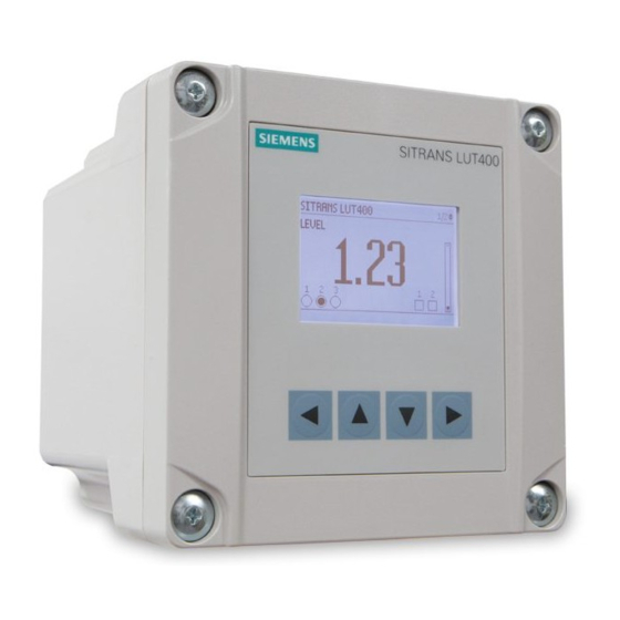
Sign In
Upload
Manuals
Brands
Siemens Manuals
Controller
SITRANS LUT400
Siemens SITRANS LUT400 Manuals
Manuals and User Guides for Siemens SITRANS LUT400. We have
5
Siemens SITRANS LUT400 manuals available for free PDF download: Operating Instructions Manual, Manual, Application Manual
Siemens SITRANS LUT400 Operating Instructions Manual (601 pages)
HART Ultrasonic Controllers
Brand:
Siemens
| Category:
Controller
| Size: 10.21 MB
Table of Contents
Italiano
14
Table of Contents
14
Introduzione
20
Manuale
20
Simboli Nel Manuale
20
Esempi DI Applicazioni
20
Cronologia Delle Modifiche
21
Nodo Sensore
21
Lui
21
Note Sulla Sicurezza
22
Simboli Grafici DI Sicurezza
22
Conformità FCC
23
Conformità EMC (Compatibilità Elettromagnetica CE)
23
Descrizione
26
Panoramica
26
Caratteristiche
26
Modelli
27
Applicazioni
27
Approvazioni E Certificati
27
Installazione E Montaggio
28
Posizioni DI Montaggio
28
Istruzioni DI Montaggio
29
Montaggio Su Pannello O a Parete
29
Coperchio a Montaggio Remoto
31
Montaggio Su Tubo
32
Montaggio Su Guida DIN
34
Preparazione All'inserimento Dei Cavi
35
Instradamento Dei Cavi Tramite Canalina
35
Esposizione Dei Cavi E Inserimento Tramite I Serracavi
36
Comparto DI Cablaggio DI SITRANS LUT400
36
Batteria
36
Collegamento
38
Note Sulla Sicurezza Per Il Collegamento
38
Collegamento DI SITRANS LUT400
39
Comparto DI Cablaggio
39
Alimentazione
40
Cavi
41
Trasduttori
42
Sensore DI Temperatura
42
Relè
43
Comunicazioni
43
Collegamento Tramite USB
44
Collegamento HART
45
Sincronizzazione con Il Sistema DI Livello
46
Ingressi Discreti
47
Coperchio a Montaggio Remoto con Cavo DI Prolunga
48
Cavo DI Prolunga
49
Collegamento Nelle Installazioni in Aree Pericolose
50
Messa in Esercizio
52
Messa in Esercizio Locale
52
Attivazione DI SITRANS LUT400
52
Display LCD
53
Display del Modo Misurazione: Funzionamento Normale
53
Display del Modo PROGRAMMA
54
Funzioni Dei Tasti Nel Modo Misurazione
54
Programmazione DI SITRANS LUT400
54
Procedure Guidate Avvio Rapido
57
Procedure Guidate Avvio Rapido Tramite LUI
57
Richiesta DI un Profilo DI Eco
76
Indirizzo Dispositivo
76
Prova Della Configurazione
76
Esempi DI Applicazioni
77
Esempio DI Applicazione Livello
77
Esempio DI Applicazione Portata
78
Funzionamento Generale
82
Avvio Della Misurazione
82
Condizioni DI Misurazione
82
Velocità DI Risposta
82
Dimensioni
82
Fail-Safe
82
Relè
83
Introduzione Generale
83
Funzione Relè
84
Allarme
84
Pompa
84
Varie
85
Comportamento Dei Relè in Condizioni Fail-Safe
85
Stati Dei Relè
86
Parametri Correlati Ai Relè
86
Relè Controllati Tramite Le Comunicazioni HART
88
Ingressi Discreti
88
Override Livello DI Backup
88
Funzionamento DI Base
88
Parametri Della Funzione Override Livello DI Backup
88
Condizioni DI Override del Livello
89
Effetto Della Funzione Override Livello DI Backup
89
Considerazioni Aggiuntive
89
Interblocchi Delle Pompe
89
Allarme (DI) Interruttore
89
Logica Ingressi Discreti
90
Controllo in Ma
91
Uscita in Ma
91
Verifica Dell'intervallo in Ma
91
Volume
92
Letture
92
Forma E Dimensioni del Recipiente
92
Diagramma DI Caratterizzazione
92
Allarmi
95
Livello
95
Intervallo Entro I Limiti/Oltre I Limiti
96
Temperatura
97
Allarme (Ingresso Discreto) Interruttore
97
Allarme DI Guasto Fail-Safe
98
Portata
98
Comando Pompe
98
Opzioni Della Funzione Comando Pompe
99
Algoritmi Della Funzione Comando Pompe
99
Impostazione DI un Gruppo DI Riduzione del Livello (Pozzetto DI Raccolta)
99
Altri Algoritmi Della Funzione Comando Pompe
101
Impostazione DI un Gruppo DI Aumento del Livello (Serbatoio)
104
Interblocchi Della Funzione Comando Pompe
106
Altri Controlli Delle Pompe
106
Totale del Volume Pompato
107
Impostazione DI una Pompa Sul Funzionamento Continuo
107
Impostazione Dei Ritardi DI Avvio Delle Pompe
108
Riduzione Dell'accumulo Sulle Pareti
109
Risparmio Energetico
110
Registrazione Dell'utilizzo Delle Pompe
111
Altri Controlli
111
Relè a Tempo
111
Portata
112
Calcolo Della Portata
112
Totale Della Portata
112
Totalizzatori Esterni E Campionatori Della Portata
112
Contatti Dei Relè
113
Totalizzatore
114
Campionatore Della Portata
115
Monitoraggio del Canale Aperto (OCM)
116
Metodo DI Calcolo Della Portata
117
Parametri Comuni
117
Impostazione del Battente Zero
118
PMD con Funzione Esponenziale Portata/Battente
119
Profili DI Sbarramento Applicabili
119
Canale Parshall
120
Canale Leopold Lagco
121
Canale con Strozzatura
122
Canale Khafagi-Venturi
123
Supporto al Calcolo Universale
135
Caratterizzazione Tipica Della Portata
135
Esempio DI Canali
136
Esempio DI Sbarramenti
137
Tendenze
137
Data Logging
138
Visualizzazione del Data Log
138
Simulazione
139
Comportamento Dei Relè Delle Pompe Durante la Simulazione
140
Fail-Safe E Simulazione
141
Stato HART
141
Processo DI Simulazione
141
Prova Dell'applicazione
142
Sistemi DI Comunicazione DI SITRANS LUT400
143
Comunicazioni DI LUT400 (HART)
143
Versione HART
143
Modo Burst
144
Modo Multi-Drop HART
144
Simatic Pdm
144
Descrizione Dell'apparecchiatura Elettronica (EDD) HART
144
Stato HART
144
Collegamenti DI Comunicazione DI LUT400
144
Configurazione Delle Porte DI Comunicazione
145
Modem HART
145
Cavo USB
145
Guida Alla Soluzione Dei Problemi DI Comunicazione
145
Funzionamento in Remoto
146
Funzionamento Tramite SIMATIC PDM 6 (HART)
146
Caratteristiche E Funzioni
146
Avvio E Configurazione
146
Versione DI SIMATIC PDM
147
Descrizione Dell'apparecchiatura Elettronica (EDD)
147
Funzionamento Tramite Browser Web (USB)
148
Caratteristiche E Funzioni
148
Avvio E Configurazione
148
Funzionamento Tramite AMS Device Manager (HART)
150
Caratteristiche E Funzioni
150
Avvio E Configurazione
150
Descrizione Dell'apparecchiatura Elettronica (EDD)
150
Funzionamento Tramite Field Communicator 375/475 (FC375/FC475) (HART)
152
Caratteristiche E Funzioni
152
Avvio E Configurazione
152
Funzionamento Tramite FDT (Field Device Tool)
154
Caratteristiche E Funzioni
154
Avvio E Configurazione
154
Device Type Manager (DTM)
154
SITRANS DTM Versione 3.1
154
Descrizione Dell'apparecchiatura Elettronica (EDD)
154
Riferimento Ai Parametri (LUI)
156
Procedure Guidate
156
Setup
157
Manutenzione E Diagnostica
217
Comunicazione
234
Sicurezza
235
Lingua
236
Elenco Dei Parametri in Ordine Alfabetico
237
Servizio E Manutenzione
244
Aggiornamenti del Firmware
244
Trasferimento Dei Parametri Tramite Il Coperchio con Display DI LUT400
244
Sostituzione Della Batteria
245
Dichiarazione DI Decontaminazione
246
Diagnosi E Guida Alla Soluzione Dei Problemi
248
Guida Alla Soluzione Dei Problemi DI Comunicazione
248
Icone DI Stato del Dispositivo
249
Codice DI Guasto Generico
250
Tabella Dei Problemi Comuni
253
Problemi DI Rumore
259
Determinazione Della Sorgente DI Rumore
259
Sorgenti DI Rumore Indipendenti Dal Trasduttore
260
Problemi Comuni DI Cablaggio
260
Riduzione del Rumore Elettrico
260
Riduzione del Rumore Acustico
261
Difficoltà DI Misurazione
261
Perdita DI Eco (LOE)
261
Regolazione del Puntamento del Trasduttore
261
Aumento del Valore del Timer Fail-Safe
262
Installazione DI un Trasduttore con un Fascio Più Stretto
262
Lettura Fissa
262
Ostruzioni del Fascio Acustico
262
Montaggi Su Augello
262
Impostazione DI SITRANS LUT400 Per Ignorare L'eco Difettosa
263
Lettura Errata
263
Tipi DI Letture Errate
263
Spruzzi DI Liquido
263
Regolazione Dell'algoritmo Dell'eco
263
Chiamata del Trasduttore
264
Visualizzazione del Profilo DI Eco
264
Visualizzazione Delle Tendenze
264
Dati Tecnici
266
Alimentazione
266
Prestazioni
266
Interfaccia
267
Dati Meccanici
269
Ambiente
269
Approvazioni
270
Disegni Dimensionali
272
Appendice A - Riferimento Tecnico
274
Principi DI Funzionamento
274
Variabili DI Processo
274
Impulso DI Trasmissione
274
Elaborazione Dell'eco
274
Selezione Dell'eco
275
Soglia DI Variazione del Tempo (TVT)
275
Algoritmo
276
Confidenza
276
Soglia Eco
276
Fattore DI Merito
277
Modo Regolatore E Eliminazione Automatica Falsi Echi
277
Intervallo DI Misurazione
278
Risposta DI Misurazione
279
Smorzamento
279
Uscita Analogica
280
Funzione Uscita DI Corrente (2.6.1.)
280
Perdita DI Eco (LOE)
280
Modo Fail-Safe
280
Calcolo Della Distanza
281
Velocità Suono
281
Calcolo del Volume
282
Totalizzatori Delle Pompe
283
Regolazione Afflusso/Scarico
283
Calcolo Della Portata
284
Metodo DI Calcolo Della Portata
285
Data Logging
286
Appendice B - Certificati E Assistenza
288
Certificati
288
Assistenza Tecnica
288
Service & Support Su Internet
288
Ulteriore Assistenza
288
Elenco Delle Abbreviazioni
290
Struttura Dei Menu del Display LCD
292
Glossario
298
Indice Analitico
300
Advertisement
Siemens SITRANS LUT400 Operating Instructions Manual (330 pages)
Ultrasonic controllers
Brand:
Siemens
| Category:
Controller
| Size: 13.8 MB
Table of Contents
Table of Contents
5
1 Introduction
15
The Manual
15
Manual Symbols
15
Application Examples
16
Change History
16
Sensor Node
16
Lui
16
Security Information
17
2 Safety Notes
18
Safety Marking Symbols
18
FCC Conformity
19
CE Electromagnetic Compatibility (EMC) Conformity
19
3 Description
21
Features
21
Models
22
Applications
22
Approvals and Certificates
22
4 Installing and Mounting
23
Mounting Locations
23
Mounting Instructions
24
Wall or Panel Mount
24
Remote Mounted Lid
26
Mounting the Remote Lid
27
Pipe Mount
28
Mounting the Enclosure
28
DIN-Rail Mount
30
Mounting the Enclosure
31
Removing the Enclosure
31
Preparation for Cable Entry
31
Cable Routed through Conduit
31
Cable Exposed and Entering through the Cable Glands
32
SITRANS LUT400 Wiring Compartment
33
The Battery
33
5 Connecting
34
Connecting SITRANS LUT400
36
Wiring Compartment
37
Power
37
Cables
40
Transducers
40
Temperature Sensor
41
Relays
42
Communications
43
Connecting Via USB
43
Connecting HART
45
Level System Synchronization
46
Discrete Inputs
47
Remote Mounted Lid with Extension Cable
48
Extension Cable
50
Connecting in Hazardous Area Installations
51
6 Commissioning
52
Local Commissioning
52
Activating SITRANS LUT400
53
The LCD Display
54
Measurement Mode Display: Normal Operation
54
PROGRAM Mode Display
55
Key Functions in Measurement Mode
56
Programming SITRANS LUT400
56
Quick Start Wizards
59
Quick Start Wizards Via LUI
60
Quick Start
61
QS Volume
65
QS Flow
69
Pump Control
76
Accuracy
79
Requesting an Echo Profile
80
Device Address
80
Testing the Configuration
81
Application Examples
81
Level Application Example
81
Flow Application Example
82
Parshall Flume
82
7 General Operation
85
Starting Measurement
85
Measurement Conditions
85
Response Rate
85
Dimensions
86
Fail-Safe
86
Relays
86
General Introduction
87
Relay Function
88
Alarm
88
Pump
89
Miscellaneous
89
Relay Behaviour under Fail-Safe Conditions
89
Alarm Relays
89
Pump Relays
90
Miscellaneous Relays
90
Relay States
91
Relay Output Logic
91
Relay Related Parameters
91
Relays Controlled by HART Communications
93
Discrete Inputs
93
Backup Level Override
93
Basic Operation
94
Backup Level Override Parameters
94
Level Override Conditions
94
Effect of Backup Level Override
95
Additional Considerations
95
Pump Interlocks
95
Switch (DI) Alarm
95
Discrete Input Logic
95
Ma Control
96
Ma Output
96
Verifying the Ma Range
97
Volume
97
Readings
97
Vessel Shape and Dimensions
97
Characterization Chart
99
Example Chart (with 15 of Possible 32 Level and Volume Breakpoints Defined)
99
Alarms
101
Set the Common Parameters
101
Level
102
In-Bounds/ Out-Of-Bounds Range
102
Example: Setting an In-Bounds Level Alarm
102
Example: Setting an Out-Of-Bounds Level Alarm
103
Temperature
103
Switch (Discrete Input) Alarm
104
Fail-Safe Fault Alarm
104
Flowrate
105
Pump Control
105
Pump Control Options
105
Pump Control Algorithms
106
Setting a Pump down (Wet Well) Group
106
Set the Common Parameters
107
Set Relays to ALTERNATE DUTY ASSIST (ADA)
107
Set the on Setpoints
107
Set the off Setpoints
108
Other Pump Control Algorithms
108
Set Relays to ALTERNATE DUTY BACKUP (ADB)
108
Set Relays to FIXED DUTY ASSIST (FDA)
109
Set Relays to FIXED DUTY BACKUP (FDB)
109
Set Relays to SERVICE RATIO DUTY ASSIST (SRA)
110
Set Relays to SERVICE RATIO DUTY BACKUP (SRB)
111
Setting a Pump up (Reservoir) Group
112
Set the Common Parameters
113
Set Relays to ALTERNATE DUTY ASSIST (ADA)
113
Set the on Setpoints
113
Set the off Setpoints
113
Pump Control Interlocks
114
Other Pump Controls
115
Totalizing Pumped Volume
115
Setting a Pump to Run-On
116
Setting the Pump Start Delays
116
Reducing Wall Cling
116
Saving Energy
117
Tracking Pump Usage
119
Other Controls
119
Relays Controlled by Time
119
Flow
120
Flow Calculation
120
Totalizing Flow
120
External Totalizers and Flow Samplers
120
Relay Contacts
121
Totalizer
121
Flow Sampler
122
Open Channel Monitoring (OCM)
123
Method of Flow Calculation
124
Common Parameters
124
Setting Zero Head
125
Pmds with Exponential Flow to Head Function
126
Standard Weirs
126
Applicable Weir Profiles
126
Parshall Flume
128
Leopold Lagco Flume
129
Cut Throat Flume
130
Khafagi Venturi
131
Universal Calculation Support
149
Typical Flow Characterization
150
Example Flumes
151
Example Weirs
152
Trends
153
Data Logging
154
Viewing the Data Log
154
Simulation
155
Pump Relay Behaviour During Simulation
156
Fail-Safe and Simulation
157
HART Status
157
Simulation Process
157
Simulating a Fixed Level
158
Simulating a Changing Level
158
Simulating Discrete Inputs
158
Simulation Timeout
159
Application Test
159
SITRANS LUT400 Communication Systems
160
LUT400 Communications (HART)
160
HART Version
160
Burst Mode
160
HART Multi-Drop Mode
161
Simatic Pdm
161
HART Electronic Device Description (EDD)
161
HART Status
161
LUT400 Communication Connections
161
Configuring Communication Ports
162
HART Modem
162
USB Cable
162
Communication Troubleshooting
162
8 Remote Operation
163
Operation Via SIMATIC PDM 6 (HART)
163
Startup and Configuration
164
SIMATIC PDM Version
164
Electronic Device Description (EDD)
164
Operation Via Web Browser (USB)
165
Features and Functions
165
Startup and Configuration
165
Operation Via AMS Device Manager (HART)
166
Features and Functions
166
Startup and Configuration
166
Electronic Device Description (EDD)
166
Operation Via Field Communicator
167
Features and Functions
167
Startup and Configuration
167
Operation Via FDT (Field Device Tool)
167
Startup and Configuration
168
Device Type Manager (DTM)
168
SITRANS DTM Version 3.1
168
Electronic Device Description (EDD)
168
9 Parameter Reference (LUI)
169
Wizards (1.)
170
Setup (2.)
170
Sensor (2.1)
170
Units (2.1.1.)
170
Sensor Mode (2.1.2.)
170
Sensor Mode (2.1.3.)
171
Sensor Mode Secondary (2.1.4.)
172
Sensor Mode Secondary (2.1.5.)
172
Transducer (2.1.6.)
172
Frequency (2.1.7.)
173
Long Shot Duration (2.1.8.)
173
Short Shot Duration (2.1.9.)
173
Calibration (2.2.)
173
Low Calibration Point (2.2.1.)
173
High Calibration Point (2.2.2.)
174
Sensor Offset (2.2.3.)
174
Near Range (2.2.4.)
174
Far Range (2.2.5.)
174
Auto Sensor Offset (2.2.6.)
175
Rate (2.3.)
176
Fill Rate Per Minute (2.3.1.)
176
Empty Rate Per Minute (2.3.2.)
176
Damping Filter (2.3.3.)
176
Fail-Safe (2.4.)
177
Material Level (2.4.1.)
177
LOE Timer (2.4.2.)
177
Fail-Safe Ma Value (2.4.3.)
177
Current Output (2.5.)
178
Current Output Function (2.5.1.)
178
Current Output Function (2.5.2.)
178
Ma Setpoint (2.5.3.)
180
Ma Setpoint (2.5.4.)
180
Minimum Ma Limit (2.5.5.)
180
Maximum Ma Limit (2.5.6.)
181
Manual Value (2.5.7.)
181
Current Output Value (2.5.8.)
181
Volume (2.6.)
181
Vessel Shape (2.6.1.)
182
Volume Units (2.6.2.)
183
Maximum Volume (2.6.3.)
184
Dimension a (2.6.4.)
184
Dimension L (2.6.5.)
184
User Defined Unit (2.6.6.)
184
Pumps (2.7.)
186
Basic Setup (2.7.1.)
187
Modifiers (2.7.2.)
189
Totalizers (2.7.3.)
196
Alarms (2.8.)
198
High Level Alarm (2.8.1.)
198
Low Level Alarms (2.8.2.)
199
Switch (Discrete Input) Alarm (2.8.3.)
200
In-Bounds Level Alarm (2.8.4.)
201
Out-Of-Bounds Level Alarm (2.8.5.)
202
Low Temperature Alarm (2.8.6.)
203
High Temperature Alarm (2.8.7.)
204
Fail-Safe Fault Alarm (2.8.8.)
205
High Flowrate Alarm (2.8.9.)
206
Low Flowrate Alarm (2.8.10.)
207
Relay Logic (2.8.11.)
208
Time to Spill (2.8.12.)
209
Discrete Inputs (2.9.)
209
Backup Level Override (2.9.1)
210
Discrete Input Logic (2.9.2)
210
Pump Interlock (2.9.3.)
211
Data Logging (2.10.)
212
Logging Mode (2.10.1.)
212
Process Value Log (2.10.2.)
212
Alarm Log (2.10.3.)
213
Flow Log (2.10.4.)
213
Delete Logs (2.10.5.)
214
Other Control (2.11.)
214
Elapsed Time Relay (2.11.1.)
215
Time of Day Relay (2.11.2)
216
External Totalizer (2.11.3)
217
External Sampler (2.11.4.)
218
Signal Processing (2.12.)
220
Temperature and Velocity (2.12.1.)
220
Echo Select (2.12.2.)
222
TVT Setup (2.12.3.)
223
TVT Shaper (2.12.4.)
225
Measured Values (2.12.5.)
226
Display (2.13.)
228
Local Display Backlight (2.13.1.)
228
LCD Contrast (2.13.2.)
228
Date and Time (2.14.)
228
Date (2.14.1.)
229
Time (2.14.2.)
230
Daylight Saving (2.14.3.)
230
Flow (2.15.)
231
Primary Measuring Device (PMD) (2.15.1.)
232
Auto Zero Head (2.15.2.)
232
Basic Setup (2.15.3.)
233
PMD Dimensions (2.15.4.)
236
Universal Head Versus Flow (2.15.5.)
238
Totalizers (2.16.)
239
Daily Totalizer (2.16.1.)
240
Running Totalizer (2.16.2.)
240
Totalizer Decimal Position (2.16.3.)
240
Totalizer Multiplier (2.16.4.)
240
Reset Daily Totalizer (2.16.5.)
241
Reset Running Totalizer (2.16.6.)
241
Maintenance and Diagnostics (3.)
241
Identification (3.1.)
241
Tag (3.1.1.)
241
Long TAG (3.1.2.)
241
Descriptor (3.1.3.)
241
Message (3.1.4.)
242
Installation Date (3.1.5.)
242
Product (3.1.6.)
242
Order No. (Order Number in PDM) (3.1.7.)
242
Serial Number (3.1.8.)
242
Final Assembly Number (3.1.9.)
242
Hardware Revision (3.1.10.)
242
Firmware Revision (3.1.11.)
242
Loader Revision (3.1.12.)
243
Manufacture Date (Date of Manufacturing in PDM) (3.1.13.)
243
Order Option (3.1.14.)
243
Diagnostics (3.2.)
243
Echo Profile (3.2.1.)
243
Trend (3.2.2.)
244
Master Reset (3.2.3.)
244
Power-On Resets (3.2.4.)
244
Power-On Time (3.2.5.)
244
View Logs (3.2.6.)
245
Pump Records (3.2.7.)
245
Temperature Peak Values (3.2.8.)
246
Echo Quality (3.2.9.)
246
Maintenance (3.3.)
247
Transducer Enable (3.3.1.)
247
Backup Control (3.3.2.)
248
Remaining Device Life (3.3.3.)
248
Remaining Sensor Life (3.3.4.)
251
Service Schedule (3.3.5.)
254
Schedule (3.3.6.)
257
Simulation (3.4.)
260
Level (3.4.1.)
260
Discrete Inputs (3.4.2.)
261
Pump Activations (3.4.3.)
261
Communication (4.)
262
Device Address (4.1.)
262
Security (5.)
263
Write Protection (5.1.)
263
User PIN (5.2.)
263
Language (6.)
264
Siemens SITRANS LUT400 Operating Instructions Manual (296 pages)
Ultrasonic Controllers
Brand:
Siemens
| Category:
Controller
| Size: 2.62 MB
Table of Contents
Table of Contents
3
Table of Contents
9
Introduction
9
The Manual
9
Manual Symbols
9
Application Examples
9
Change History
10
Sensor Node
10
Lui
10
Safety Notes
11
Safety Marking Symbols
11
FCC Conformity
12
CE Electromagnetic Compatibility (EMC) Conformity
12
Description
15
Overview
15
Features
15
Models
16
Applications
16
Approvals and Certificates
16
Installing and Mounting
17
Mounting Locations
17
Mounting Instructions
18
Wall or Panel Mount
18
Remote Mounted Lid
20
Pipe Mount
21
DIN-Rail Mount
23
Preparation for Cable Entry
24
Cable Routed through Conduit
24
Cable Exposed and Entering through the Cable Glands
25
SITRANS LUT400 Wiring Compartment
25
The Battery
25
Connecting
27
Safety Notes for Connection
27
Connecting SITRANS LUT400
28
Wiring Compartment
28
Power
29
Cables
30
Transducers
31
Temperature Sensor
31
Relays
32
Communications
32
Connecting Via USB
33
Connecting HART
34
Level System Synchronization
35
Discrete Inputs
36
Remote Mounted Lid with Extension Cable
37
Extension Cable
38
Connecting in Hazardous Area Installations
39
Commissioning
41
Local Commissioning
41
Activating SITRANS LUT400
41
The LCD Display
42
Measurement Mode Display: Normal Operation
42
PROGRAM Mode Display
43
Key Functions in Measurement Mode
43
Programming SITRANS LUT400
43
Quick Start Wizards
46
Quick Start Wizards Via LUI
46
Requesting an Echo Profile
65
Device Address
65
Testing the Configuration
65
Application Examples
66
Level Application Example
66
Flow Application Example
67
General Operation
71
Starting Measurement
71
Measurement Conditions
71
Response Rate
71
Dimensions
71
Fail-Safe
71
Relays
72
General Introduction
72
Relay Function
73
Alarm
73
Pump
73
Miscellaneous
74
Relay Behaviour under Fail-Safe Conditions
74
Relay States
75
Relay Related Parameters
75
Relays Controlled by HART Communications
77
Discrete Inputs
77
Backup Level Override
77
Basic Operation
77
Backup Level Override Parameters
77
Level Override Conditions
78
Affect of Backup Level Override
78
Additional Considerations
78
Pump Interlocks
78
Switch (DI) Alarm
78
Discrete Input Logic
79
Ma Control
80
Ma Output
80
Verifying the Ma Range
80
Volume
81
Readings
81
Vessel Shape and Dimensions
81
Characterization Chart
81
Alarms
84
Level
84
In-Bounds/ Out-Of-Bounds Range
85
Temperature
86
Switch (Discrete Input) Alarm
86
Fail-Safe Fault Alarm
87
Flowrate
87
Pump Control
87
Pump Control Options
88
Pump Control Algorithms
88
Setting a Pump down (Wet Well) Group
88
Other Pump Control Algorithms
90
Setting a Pump up (Reservoir) Group
93
Pump Control Interlocks
95
Other Pump Controls
95
Totalizing Pumped Volume
96
Setting a Pump to Run-On
96
Setting the Pump Start Delays
97
Reducing Wall Cling
98
Saving Energy
99
Tracking Pump Usage
100
Other Controls
100
Relays Controlled by Time
100
Flow
101
Flow Calculation
101
Totalizing Flow
101
External Totalizers and Flow Samplers
101
Relay Contacts
102
Totalizer
103
Flow Sampler
104
Open Channel Monitoring (OCM)
105
Method of Flow Calculation
106
Common Parameters
106
Setting Zero Head
107
Pmds with Exponential Flow to Head Function
108
Applicable Weir Profiles
108
Parshall Flume
109
Leopold Lagco Flume
110
Cut Throat Flume
111
Khafagi Venturi
112
Universal Calculation Support
124
Typical Flow Characterization
124
Example Flumes
125
Example Weirs
126
Trends
126
Data Logging
127
Viewing the Data Log
127
Simulation
128
Pump Relay Behaviour During Simulation
129
Fail-Safe and Simulation
130
HART Status
130
Simulation Process
130
Application Test
131
SITRANS LUT400 Communication Systems
132
LUT400 Communications (HART)
132
HART Version
132
Burst Mode
133
HART Multi-Drop Mode
133
Simatic Pdm
133
HART Electronic Device Description (EDD)
133
HART Status
133
LUT400 Communication Connections
133
Configuring Communication Ports
134
HART Modem
134
USB Cable
134
Communication Troubleshooting
134
Remote Operation
135
Operation Via SIMATIC PDM 6 (HART)
135
Features and Functions
135
Startup and Configuration
135
SIMATIC PDM Version
136
Electronic Device Description (EDD)
136
Operation Via Web Browser (USB)
137
Features and Functions
137
Startup and Configuration
137
Operation Via AMS Device Manager (HART)
139
Features and Functions
139
Startup and Configuration
139
Electronic Device Description (EDD)
139
Operation Via Field Communicator 375/475 (FC375/FC475) (HART)
141
Features and Functions
141
Startup and Configuration
141
Operation Via FDT (Field Device Tool)
143
Features and Functions
143
Startup and Configuration
143
Device Type Manager (DTM)
143
SITRANS DTM Version 3.1
143
Electronic Device Description (EDD)
143
Advertisement
Siemens SITRANS LUT400 Manual (140 pages)
Communications (HART)
Brand:
Siemens
| Category:
Controller
| Size: 3.99 MB
Table of Contents
Table of Contents
3
Introduction
5
Overview
5
Safety Notes
5
The Manual
5
Technical Support
6
Service & Support on the Internet
6
Additional Support
6
Abbreviations and Identifications
7
Operation Via SIMATIC PDM 6 (HART)
9
Features
9
Functions
9
SIMATIC PDM Version
10
Electronic Device Description (EDD)
10
Configuring a New Device
11
Quick Start Wizard Via SIMATIC PDM
11
Quick Start (Level)
13
Quick Start (Volume)
16
Quick Start (Volume - Linearization)
19
Quick Start (Flow)
23
Pump Control Wizard
26
Changing Parameter Settings Using SIMATIC PDM
28
Parameters Accessed Via Pull-Down Menus
29
Pull-Down Menus Device Menus Page View Menus Page
30
Echo Profile Utilities
31
Set Address
31
Maintenance
36
Process Variables
40
Operation Via Web Browser (USB)
45
Features
45
Functions
45
Installation
45
Installing the USB Driver
45
Installing the Web Browser Interface
46
Accessing the Device Via the Web Browser
47
Changing Parameter Settings Using the Browser
49
Configuring a New Device
49
Browser Menu Parameter Function Groups
50
Number *
51
Operation Via AMS Device Manager (HART)
53
Features
53
Functions
53
Electronic Device Description (EDD)
54
Configuring a New Device
54
Startup
54
Master Reset
56
Pull-Down Menu Access
56
Scan Device
56
Device Configuration
57
Quick Start Wizards Via AMS Device Manager
58
Wizard - Quick Start (Level)
59
Wizard - Quick Start (Volume)
61
Wizard - Quick Start (Volume - Linearization)
64
Wizard - Quick Start (Flow)
67
Wizard - Pump Control
70
Changing Parameter Settings Using AMS Device Manager
72
Auto Zero Head
72
Auto Sensor Offset
72
Auto Sound Velocity
72
Real Time Clock
72
Select Analog Output
72
Discrete Inputs
75
Data Logging 2. 1
75
Other Control
75
Signal Processing
75
Temperature and Velocity
75
Echo Select
75
TVT Setup
76
TVT Shaper
76
Display
76
Date and Time
76
Daylight Saving
76
Flow
76
Device Diagnostics View
79
Process Variables View
80
Password Protection
80
User Manager Utility
81
AMS Menu Structure
82
Auto Zero Head
88
Basic Setup
90
Totalizers
90
Diagnostics
95
Operation Via Field Communicator 375/475 (FC375/FC475) (HART)
101
Features
101
Functions
101
Configuring a New Device
101
HART FC375/FC475 Menu Structure
102
Pump Records
110
Echo Quality
110
Maintenance
110
Remaining Device Lifetime
110
Remaining Sensor Lifetime
110
Service Schedule
111
Calibration Schedule
111
Operation Via FDT (Field Device Tool)
137
Features
137
Functions
137
Device Type Manager (DTM)
137
SITRANS DTM Version 3.1
137
Electronic Device Description (EDD)
137
Configuring a New Device
137
Siemens SITRANS LUT400 Application Manual (16 pages)
Communications Options, Connecting to a control system and the available data
Brand:
Siemens
| Category:
Controller
| Size: 0.41 MB
Share and save
Advertisement
Related Products
Siemens SITRANS LUT430
Siemens SITRANS LUT440
Siemens SITRANS LUT420
Siemens LME21.350A1
Siemens LME22.131A2
Siemens LME44.057A1
Siemens LME75
Siemens LGK16.335A27
Siemens LMG21.330A27
Siemens LMV60.110A2
Siemens Categories
Controller
Control Unit
Industrial Equipment
Washer
Switch
More Siemens Manuals
Login
Sign In
OR
Sign in with Facebook
Sign in with Google
Upload manual
Upload from disk
Upload from URL