Table of Contents
Advertisement
Quick Links
SITRANS L
Ultrasonic level controllers
SITRANS LUT400
Operating Instructions
7ML5400 (SITRANS LUT400)
04/2021
A5E33329501-AG
Introduction
Safety Notes
Description
Installing and Mounting
Connecting
Commissioning
General Operation
Remote Operation
Parameter reference (LUI)
Service and Maintenance
Diagnosing and
Troubleshooting
Technical data
Dimension drawings
Technical reference
Product documentation and
support
List of abbreviations
LCD menu structure
1
2
3
4
5
6
7
8
9
10
11
12
13
A
B
C
D
Advertisement
Table of Contents
Troubleshooting

Subscribe to Our Youtube Channel
Related Manuals for Siemens SITRANS L 7ML5400


Summary of Contents for Siemens SITRANS L 7ML5400
- Page 1 Introduction Safety Notes SITRANS L Description Installing and Mounting Ultrasonic level controllers SITRANS LUT400 Connecting Commissioning Operating Instructions General Operation Remote Operation Parameter reference (LUI) Service and Maintenance Diagnosing and Troubleshooting Technical data Dimension drawings Technical reference 7ML5400 (SITRANS LUT400) Product documentation and support List of abbreviations...
- Page 2 Note the following: WARNING Siemens products may only be used for the applications described in the catalog and in the relevant technical documentation. If products and components from other manufacturers are used, these must be recommended or approved by Siemens. Proper transport, storage, installation, assembly, commissioning, operation and maintenance are required to ensure that the products operate safely and without any problems.
-
Page 3: Table Of Contents
Table of contents Introduction ............................13 The Manual ........................13 1.1.1 Manual symbols ......................... 13 1.1.2 Application examples ......................14 Change History ........................14 1.2.1 Sensor node ........................14 1.2.2 LUI ............................ 14 Security information ......................15 Safety Notes ............................16 Safety marking symbols ..................... - Page 4 Table of contents 5.1.3 Cables ..........................38 5.1.4 Transducers ........................38 5.1.5 Temperature sensor ......................39 5.1.6 Relays ..........................40 5.1.7 Communications ....................... 41 5.1.7.1 Connecting via USB ......................41 5.1.7.2 Connecting HART ....................... 43 5.1.8 Level system synchronization ..................... 44 5.1.9 Discrete inputs ........................
- Page 5 Table of contents 7.2.3 Relay behaviour under fail-safe conditions ................87 7.2.3.1 Alarm relays........................87 7.2.3.2 Pump relays ........................88 7.2.3.3 Miscellaneous relays ......................88 7.2.4 Relay states ........................89 7.2.4.1 Relay output logic ......................89 7.2.4.2 Relay related parameters ....................89 7.2.5 Relays controlled by HART Communications ...............
- Page 6 Table of contents 7.7.4 Setting a pump up (reservoir) group ................111 7.7.4.1 Set the common parameters .................... 111 7.7.4.2 Set Relays to ALTERNATE DUTY ASSIST (ADA) ..............112 7.7.4.3 Set the ON Setpoints ......................112 7.7.4.4 Set the OFF Setpoints ...................... 112 7.7.5 Pump Control Interlocks ....................
- Page 7 Table of contents 7.14.5 Application test ........................ 159 7.15 SITRANS LUT400 Communication Systems ............... 160 7.15.1 LUT400 Communications (HART) ..................160 7.15.1.1 HART Version ........................160 7.15.1.2 Burst mode ........................160 7.15.1.3 HART multi-drop mode..................... 161 7.15.1.4 SIMATIC PDM ........................161 7.15.1.5 HART Electronic Device Description (EDD) ................
- Page 8 Table of contents 9.2.1.9 Short Shot Duration (2.1.9.) ..................... 175 9.2.2 Calibration (2.2.) ......................176 9.2.2.1 Low Calibration Point (2.2.1.) ..................176 9.2.2.2 High Calibration Point (2.2.2.) ..................176 9.2.2.3 Sensor Offset (2.2.3.) ...................... 176 9.2.2.4 Near Range (2.2.4.) ......................176 9.2.2.5 Far Range (2.2.5.) ......................
- Page 9 Table of contents 9.2.9.1 Backup Level Override (2.9.1) ..................211 9.2.9.2 Discrete Input Logic (2.9.2) ....................212 9.2.9.3 Pump Interlock (2.9.3.) ....................213 9.2.10 Data Logging (2.10.) ......................214 9.2.10.1 Logging Mode (2.10.1.) ....................214 9.2.10.2 Process Value Log (2.10.2.) ....................214 9.2.10.3 Alarm Log (2.10.3.) ......................
- Page 10 Table of contents 9.3.1.11 Firmware Revision (3.1.11.) ..................... 245 9.3.1.12 Loader Revision (3.1.12.) ....................245 9.3.1.13 Manufacture Date (Date of Manufacturing in PDM) (3.1.13.) ..........245 9.3.1.14 Order Option (3.1.14.) ..................... 245 9.3.2 Diagnostics (3.2.) ......................246 9.3.2.1 Echo Profile (3.2.1.) ......................246 9.3.2.2 Trend (3.2.2.) ........................
- Page 11 Table of contents 11.5 Noise Problems ........................ 280 11.5.1 Determine the Noise Source ..................... 280 11.5.1.1 Acoustical Noise ......................281 11.5.2 Non-Transducer Noise Sources ..................281 11.5.3 Common Wiring Problems ....................282 11.5.4 Reducing Electrical Noise ....................282 11.5.5 Reducing Acoustical Noise ....................282 11.6 Measurement Difficulties ....................
- Page 12 Table of contents Echo Processing ....................... 295 A.2.1 Echo Selection ......................... 295 A.2.1.1 Time Varying Threshold (TVT) ..................295 A.2.1.2 Algorithm ........................296 A.2.1.3 Confidence ........................297 A.2.1.4 Echo Threshold ........................ 297 A.2.1.5 Figure of Merit ......................... 297 A.2.2 Measurement Range ......................299 A.2.3 Measurement Response ....................
-
Page 13: Introduction
Introduction The Manual This manual will help you set up your SITRANS LUT400 for optimum performance. For other Siemens level measurement manuals, go to: www.siemens.com/level (www.siemens.com/level), and look under Level Measurement. Note • This product is intended for use in industrial areas. Operation of this equipment in a residential area may cause interference to several frequency-based communications. -
Page 14: Application Examples
Introduction 1.2 Change History 1.1.2 Application examples The application examples used in this manual illustrate typical installations using SITRANS LUT400. As there is often a range of ways to approach an application, other configurations may also apply. In all examples, substitute your own application details. If the examples do not apply to your application, check the applicable parameter reference for the available options. -
Page 15: Security Information
In order to protect plants, systems, machines and networks against cyber threats, it is necessary to implement – and continuously maintain – a holistic, state-of-the-art industrial security concept. Siemens’ products and solutions form one element of such a concept. Customers are responsible for preventing unauthorized access to their plants, systems, machines and networks. -
Page 16: Safety Notes
Safety Notes Special attention must be paid to warnings and notes highlighted from the rest of the text by grey boxes. WARNING: relates to a caution symbol on the product, and means that failure to observe the necessary precautions can result in death, serious injury, and/or con- siderable material damage. -
Page 17: Fcc Conformity
US Installations only: Federal Communications Commission (FCC) rules Note Void user authority Changes or modifications not expressly approved by Siemens could void the user’s authority to operate the equipment. Note This equipment has been tested and found to comply with the limits for a Class A digital device, pursuant to Part 15 of the FCC Rules. - Page 18 CO concentrations), should be properly assessed to ensure safe reliable use in the event of measurement errors due to sound wave velocity changes. Please contact your local Siemens representative for assistance. SITRANS LUT400...
-
Page 19: Description
Description The Siemens SITRANS LUT400 series controllers are compact, single point, long-range ultrasonic controllers for continuous level measurement of liquids, slurries, and solids, and high accuracy monitoring of open channel flow. The series is compatible with Siemens full line of EchoMax Transducers, allowing an ®... -
Page 20: Models
Description 3.2 Models • Real time clock with daylight savings time supporting an integrated datalogger and energy saving algorithms for minimizing pump operation during high cost energy periods • Removable terminal blocks for ease of wiring. Models The SITRANS LUT400 comes in three different models, depending on the application, level of performance and functionality required: •... -
Page 21: Installing And Mounting
Installing and Mounting Note • Installation must only be performed by qualified personnel, and in accordance with local governing regulations. • This product is susceptible to electrostatic shock. Follow proper grounding procedures. CAUTION • All field wiring must have insulation suitable for at least 250V. •... -
Page 22: Mounting Instructions
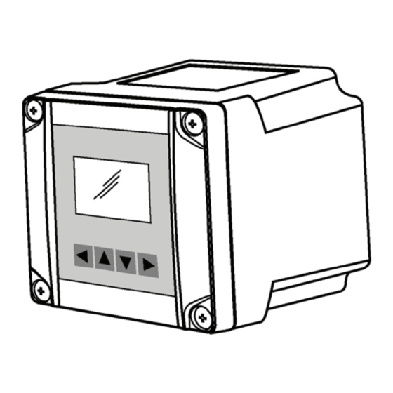
Installing and Mounting 4.2 Mounting instructions Mounting instructions Mounting instructions differ for wall, pipe, DIN-rail, and remote display panel mount devices. Please follow the specific instructions for your device. Note Some electrical codes require use of metal conduit. When routing cable through a conduit, please follow the Cable Routing instructions (Page 29) before mounting the SITRANS LUT400. - Page 23 Installing and Mounting 4.2 Mounting instructions ① Enclosure with blank lid ② Mounting back plate ③ Fasteners ④ Clips (2 places) Note Wall mount fasteners not included. ① Slotted features For a more detailed dimension drawing, see SITRANS LUT400 Dimensions (Page 292). 1.
-
Page 24: Remote Mounted Lid
Installing and Mounting 4.2 Mounting instructions ① Mounting screw holes on the back plate Note • Recommended fastener size: M8 or 5/16 " screw with washer of maximum 17 mm or 5/8 " outside diameter. • Recommended mounting: mount directly to wall. If alternate mounting surface is used, it MUST be able to support four times the weight of the device. -
Page 25: Mounting The Remote Lid
Installing and Mounting 4.2 Mounting instructions 4.2.1.2 Mounting the remote lid Note Remote mounted lid can be mounted up to 5 m from the device using two optional cable extensions (each 2.5 m in length). For instructions on how to connect an extension cable, see Remote mounted lid with extension cable (Page 46). -
Page 26: Pipe Mount
Installing and Mounting 4.2 Mounting instructions 4.2.2 Pipe mount ① Enclosure with optional display lid ② Mounting back plate ③ Saddle clamp ④ U-bolt ⑤ Pipe Note Pipe mount fasteners not included. For a more detailed dimension drawing, see SITRANS LUT400 Dimensions (Page 292) and Cutout Dimensions (for Remote Panel Mount) (Page 293). -
Page 27: Mounting The Enclosure
Installing and Mounting 4.2 Mounting instructions 4.2.2.1 Mounting the enclosure 1. Fasten the mounting back plate to the pipe using u-bolts, saddle clamps, (customer supplied) suitable to pipe diameter. 2. Fasten bolts with a wrench. Do not over-tighten so that plate becomes twisted or bent. This may hinder ability to clip the LUT400 to the back plate. -
Page 28: Din-Rail Mount
Installing and Mounting 4.2 Mounting instructions 4.2.3 DIN-rail mount ① DIN-rail ② Back of enclosure ③ Clips (2) ④ DIN-rail slide ⑤ Slot For a more detailed dimension drawing, see SITRANS LUT400 Dimensions (Page 292). SITRANS LUT400 Operating Instructions, 04/2021, A5E33329501-AG... -
Page 29: Mounting The Enclosure
Installing and Mounting 4.2 Mounting instructions 4.2.3.1 Mounting the enclosure 1. Angle top of enclosure toward DIN-rail, and position slightly above top of rail. 2. Move enclosure downward against DIN-rail to hook clips on back of enclosure to top of DIN- rail. -
Page 30: Cable Exposed And Entering Through The Cable Glands
Installing and Mounting 4.2 Mounting instructions ① Knock-out tab (3 places) ② Cable entry holes ③ Groove for screwdriver (3 places) For a more detailed dimension drawing, see SITRANS LUT400 Dimensions (Page 292). 4.2.4.2 Cable exposed and entering through the cable glands 6. -
Page 31: Sitrans Lut400 Wiring Compartment
Installing and Mounting 4.3 SITRANS LUT400 wiring compartment SITRANS LUT400 wiring compartment ① Terminal blocks ② Power supply ③ Battery ④ USB connection ⑤ mA HART connection ⑥ Display cable The Battery The SITRANS LUT400 is supplied with one battery installed. The battery (BR2032) has a life expectancy of ten years, and is affected by ambient temperature. -
Page 32: Connecting
Connecting • Verify that all system components are installed in accordance with instructions. • Connect all cable shields to the LUT400 shield terminals (denoted on device with symbol ). To avoid differential ground potentials ensure cable shields are properly connected to ground. - Page 33 Connecting ① Siemens Transducer ② Siemens TS-3 Temperature Sensor ③ HART FC375/475 or a computer running SIMATIC PDM, AMS Device Manager, FDT, or a web browser ④ Customer Alarm, Pump, or Control Device ⑤ Customer Device with Digital Output ⑥...
-
Page 34: Connecting Sitrans Lut400
Connecting 5.1 Connecting SITRANS LUT400 Connecting SITRANS LUT400 CAUTION • Check the device label on your instrument, to verify the approval rating. • Use appropriate conduit seals to maintain IP or NEMA rating. Note Separate cables and conduits may be required to conform to standard instrumentation wiring practices or electrical codes. -
Page 35: Wiring Compartment
Connecting 5.1 Connecting SITRANS LUT400 5.1.1 Wiring compartment The terminal board on the LUT400 allows all inputs and outputs to be connected simultaneously. Terminal strips can be removed to improve ease of wiring. CAUTION Ensure the terminal strips are terminated to the correct location during re-installation. Failure to do so may result in damage to the device, or external equipment that is attached. - Page 36 Connecting 5.1 Connecting SITRANS LUT400 ① Ground ② L2/N ③ ④ Cable gland (or NPT cable entry) The SITRANS LUT400 is available in AC or DC power models. SITRANS LUT400 Operating Instructions, 04/2021, A5E33329501-AG...
- Page 37 Connecting 5.1 Connecting SITRANS LUT400 AC: 100-230 V AC 15%, 50/60 Hz, 36 VA (10W) DC: 10-32 V DC, 10W Note Make sure device is connected to a reliable ground. 1. To wire for power, strip the cable jacket for approximately 70 mm (2.75") from the end of the cable, and thread the wires through the gland 2.
-
Page 38: Cables
Connecting 5.1 Connecting SITRANS LUT400 5.1.3 Cables The SITRANS LUT400 is designed to work with two conductor shielded transducer cables. Connection Cable Type mA output, sync, 2 copper conductors, twisted, with shield /drain wire, 300V 0.324 -0.823 Temperature sensor, (22 - 18 AWG). discrete input Maximum length: 365 m Transducer... -
Page 39: Temperature Sensor
Temperature sensor The speed of sound changes as temperature changes. To ensure accurate level measurement, the SITRANS LUT400 compensates via an external temperature input. All Siemens EchoMax transducers have an internal temperature sensor for this purpose, and for the fastest temperature response, Siemens also offers a dedicated temperature sensor, the TS-3. -
Page 40: Relays
Connecting 5.1 Connecting SITRANS LUT400 To achieve the best performance of temperature measurement in a typical open channel flow application, the temperature sensor should be shielded from direct sunlight and mounted half way between the ultrasonic transducer face and the maximum head achievable in the application. -
Page 41: Communications
The USB port and the 4 to 20 mA HART terminal block (terminal numbers 22, 23, and 24) are located inside the enclosure of the device. ① To Transducer ② To other SIEMENS unit ③ USB cable connection ④ 4 to 20 mA Hart connection 5.1.7.1... - Page 42 Connecting 5.1 Connecting SITRANS LUT400 USB connection ① USB cable Use 5-pin USB Mini-B cable. The cable should not exceed 3 m (9.8 ft.). Note Do not use a USB extension cable with the LUT400. Data Logging may not occur, even after extension cable has been disconnected.
-
Page 43: Connecting Hart
Connecting 5.1 Connecting SITRANS LUT400 5.1.7.2 Connecting HART Typical PLC/mA configuration with Passive HART connection ① DC power supply (18-30V) ② ③ HART modem ④ HART communicator Typical PLC/mA configuration with Active HART connection ① ② HART modem ③ HART communicator SITRANS LUT400 Operating Instructions, 04/2021, A5E33329501-AG... -
Page 44: Level System Synchronization
The nominal value for the HART resistor is 250 Ohm. For more information see application guide Working with HART, which can be downloaded from the product page of our website. Go to: www.siemens.com/sitransLUT400 (www.siemens.com/sitransLUT400) under Support and click on Application Guides. -
Page 45: Discrete Inputs
• Use a common power (mains) supply and ground (earth) for all devices. • Interconnect the SYNC terminals of all level monitors. • Up to 16 Siemens devices can be synchronized together. For more information or assistance, contact Siemens or your local distributor. Go to: www.siemens.com/processautomation (www.siemens.com/processautomation). 5.1.9... -
Page 46: Remote Mounted Lid With Extension Cable
Connecting 5.1 Connecting SITRANS LUT400 Discrete Inputs used with external bias voltage 5.1.10 Remote mounted lid with extension cable The optional display lid can be mounted remotely up to 5 m from the device. The optional extension cable can be used for such an installation. 1. - Page 47 Connecting 5.1 Connecting SITRANS LUT400 3. Separate from the device, knock out cable entry tab on blank lid: a. With gasket in place, use snips to cut into lid on both sides of the cable entry knockout. Use cutting guideline to cut from bottom of lid, up to bottom of groove (as shown below). b.
-
Page 48: Extension Cable
Connecting 5.1 Connecting SITRANS LUT400 6. Connect extension cable to display cable on remote lid. 7. Secure blank lid on device and mount display lid remotely. See Remote mounted lid (Page 24). ① Blank lid ② Display cable connector ③ Extension cable ④... -
Page 49: Connecting In Hazardous Area Installations
In all cases, check the device label on your instrument, and confirm the approval rating. 1. Non-incendive wiring (Canada) CSA Class I, Div 2 connection drawing number A5E03936871 can be downloaded from the product page of our website at www.siemens.com/sitransLUT400 (www.siemens.com/sitransLUT400). SITRANS LUT400... -
Page 50: Commissioning
Commissioning Local Commissioning Local Commissioning SITRANS LUT400 is an easy to use, and quick to commission device, with its numerous wizards, and menu driven parameters. The parameters can be modified locally using the LCD and the local push buttons, also known as the Local User Interface (LUI). ①... -
Page 51: Activating Sitrans Lut400
1. Power up the device. SITRANS LUT400 automatically starts up in Measurement mode. A transition screen showing first the Siemens logo and then the current firmware revision of the LUI is displayed while the first measurement is being processed. -
Page 52: The Lcd Display
Commissioning 6.2 Activating SITRANS LUT400 6.2.1 The LCD Display 6.2.1.1 Measurement mode display: Normal operation Level ① ② Measured value (level, space, distance, volume, flow, or head) ③ Value being displayed [Primary Variable (PV)=1 of 2, Secondary Variable (SV)=2 of 2] ④... -
Page 53: Program Mode Display
Commissioning 6.2 Activating SITRANS LUT400 Fault present ⑧ Text area displays a fault code and an error message ⑨ Service required icon appears 6.2.1.2 PROGRAM mode display • A visible menu bar indicates the menu list is too long to display all items. •... -
Page 54: Key Functions In Measurement Mode
Commissioning 6.2 Activating SITRANS LUT400 6.2.1.3 Key functions in Measurement mode Function Result RIGHT arrow opens PROGRAM mode. Opens the top level menu. UP or DOWN arrow toggles between PV and LCD displays primary or secondary val- 6.2.2 Programming SITRANS LUT400 Note •... - Page 55 Commissioning 6.2 Activating SITRANS LUT400 Parameters are identified by name and organized into function groups, then arranged in a 5- level menu structure, as in the example below. (For full menu see LCD menu structure (Page 313).) 1. WIZARDS 2. SETUP 2.1 SENSOR ..
- Page 56 Commissioning 6.2 Activating SITRANS LUT400 Name Menu Level Function UP or DOWN Menu or Parameter Scroll to previous or next menu or parame- arrow ter. RIGHT arrow Menu Go to first parameter in the selected menu, or open next menu. Parameter Open Edit Mode.
- Page 57 Commissioning 6.2 Activating SITRANS LUT400 Changing a numeric value ① Parameter name ② Parameter number ③ Current value 1. Navigate to the desired parameter. 2. When selected, the current value is displayed. 3. Press RIGHT arrow to open Edit mode. The cursor position is highlighted. 4.
-
Page 58: Quick Start Wizards
Parameter Configuration Charts that list all parameters and available options for each application type are available on our website. Go to www.siemens.com/sitransLUT400 (www.siemens.com/sitransLUT400) > Support > Application Guides. You can record data and select from options on the chart that apply to your application, then with this data on hand, complete the Quick Start Wizards via LUI (Page 59) below, or via another Quick Start Wizard, as referenced above. -
Page 59: Quick Start Wizards Via Lui
Commissioning 6.3 Quick Start Wizards 6.3.1 Quick Start Wizards via LUI 1. Press to enter Program mode. Note Device continues to measure while in Program Mode. If you wish to disable the device while it is configured, see Transducer Enable (3.3.1.) (Page 250). 2. - Page 60 This screen is not part of the Quick Start when using SIMATIC PDM. Shows the type of Wizard to be executed. Options CANCEL, START Transducer Specifies the Siemens transducer connected to the device. Options NO TRANSDUCER, XRS-5, XPS-10, XPS-15, XCT-8, XCT-12, XPS-30, XPS-40, XLT-30, XLT-60, STH Default: NO TRANSDUCER...
- Page 61 Commissioning 6.3 Quick Start Wizards ① Distance ② Sensor reference point ③ High calibration point ④ Space ⑤ Level ⑥ Low calibration point ⑦ Far range Mode Description Reference point LEVEL Height of material Low Calibration Point (process empty level) SPACE Distance to material surface High Calibration Point...
- Page 62 Commissioning 6.3 Quick Start Wizards Units Sensor measurement units. Options m, cm, mm, ft, in Default: m Note For the purpose of this example, all values are assumed to be in meters (m). High Calibration Point Distance from Sensor Reference Point to High Calibration Point: usually process full level. Value Range: 0.000 to 60.000 Default: 0.000...
-
Page 63: Qs Volume
Commissioning 6.3 Quick Start Wizards Use a setting just faster than the maximum filling or emptying rate (whichever is greater). Slower settings provide higher accuracy, faster settings allow for more rapid level fluctuations. End of QS Level Wizard For QS to be successful, all changes must be applied. Options BACK, CANCEL, FINISH (Display returns to 1.1 Quick Start menu when Quick Start is successfully completed or... - Page 64 This screen is not part of the Quick Start when using SIMATIC PDM. Shows the type of Wizard to be executed. Options CANCEL, START Transducer Specifies the Siemens transducer connected to the device. Options NO TRANSDUCER, XRS-5, XPS-10, XPS-15, XCT-8, XCT-12, XPS-30, XPS-40, XLT-30, XLT-60, STH Default: NO TRANSDUCER...
- Page 65 Commissioning 6.3 Quick Start Wizards Temperature Source Source of the temperature reading used to adjust the speed of sound. Options TRANSDUCER, FIXED TEMPERATURE, EXTERNAL TS-3, AVERAGE OF SENSORS Default: TRANSDUCER See Temperature Source (2.12.1.3.) (Page 222) Temperature Source for more details. Fixed Temperature Use this feature if a temperature sensing device is not used.
- Page 66 Commissioning 6.3 Quick Start Wizards High Calibration Point Distance from Sensor Reference Point to High Calibration Point: usually process full level. Value Range: 0.000 to 60.000 Default: 0.000 Low Calibration Point Distance from Sensor Reference Point to Low Calibration Point: usually process empty level. Value Range: 0.000 to 60.000 Default: 60.000...
- Page 67 Commissioning 6.3 Quick Start Wizards Dimension L Length of the cylindrical section of a horizontal parabolic end vessel. Value Range: 0.000 to 99.999 Default: 0.000 Volume Units Determines volume measurement units. Value L, USGAL, IMPGAL, CUM, USER DEFINED * Default: L * If USER DEFINED option selected, the value must be set after completing the wizard.
-
Page 68: Qs Flow
Commissioning 6.3 Quick Start Wizards 6.3.1.3 QS Flow Use this wizard to configure simple flow applications. (Visible on LUT430 (Pump and Flow), and LUT440 (OCM) configured models only. 1. Press RIGHT arrow to activate PROGRAM mode and open menu level 1: MAIN MENU. 2. - Page 69 This screen is not part of the Quick Start when using SIMATIC PDM. Shows the type of Wizard to be executed. Options CANCEL, START Transducer Specifies the Siemens transducer connected to the device. Options NO TRANSDUCER, XRS-5, XPS-10, XPS-15, XCT-8, XCT-12, XPS-30, XPS-40, XLT-30, XLT-60, STH Default: NO TRANSDUCER...
- Page 70 Commissioning 6.3 Quick Start Wizards Temperature Source Source of the temperature reading used to adjust the speed of sound. Options TRANSDUCER, FIXED TEMPERATURE, EXTERNAL TS-3, AVERAGE OF SENSORS Default: TRANSDUCER See Temperature Source (2.12.1.3.) (Page 222) Temperature Source for more details. Fixed Temperature Use this feature if a temperature sensing device is not used.
- Page 71 Commissioning 6.3 Quick Start Wizards High Calibration Point Distance from Sensor Reference Point to High Calibration Point: usually process full level. Value Range: 0.000 to 60.000 Default: 0.000 Low Calibration Point Distance from Sensor Reference Point to Low Calibration Point: usually process empty level. Value Range: 0.000 to 60.000 Default: 60.000...
- Page 72 Commissioning 6.3 Quick Start Wizards K Factor (PMD = EXPONENTIAL DEVICES) The constant used in the flow calculation formula for absolute calculation of an exponential device only. Value Range: -999.000 to 9999.000 Default: 1.000 V Notch Angle (PMD = THIN PLATE V-NOTCH WEIR) The V-Notch angle used in the flow calculation formula.
- Page 73 Commissioning 6.3 Quick Start Wizards PMD selected Wizard dimension name (parameter menu reference) Round Nose Horizontal Crest Weir BS-3680 CREST WIDTH B CREST HEIGHT P CREST LENGTH L Trapezoidal Flume BS-3680 APPROACH WIDTH B THROAT WIDTH B HUMP HEIGHT P THROAT LENGTH L U-Flume BS-3680 APPROACH DIAMETER DA...
- Page 74 Commissioning 6.3 Quick Start Wizards Flowrate Units The volume units used to display total flow. Options L/S, L/MIN, CUFT/S, CUFT/D, GAL/MIN, GAL/D, IMPGAL/MIN, IMPGAL/D, CUM/H, CUM/D, MMGAL/D, USER DEFINED * Default: L/S * If USER DEFINED option selected, the value must be set after completing the wizard. See User Defined Unit (2.15.3.8.) (Page 239).
-
Page 75: Pump Control
Commissioning 6.3 Quick Start Wizards 6.3.1.4 Pump Control Use this wizard to configure pumps if they will be used in your application. Be sure to first complete the applicable Quick Start Wizard. 1. Press RIGHT arrow to activate PROGRAM mode and open menu level 1: MAIN MENU. 2. - Page 76 Commissioning 6.3 Quick Start Wizards Relay Pump 2 View only. Automatically sets the relay assigned to Pump 2 based on relay selected for Pump 1 in previous step. Options If Relay Pump 1 = RELAY 2, then Relay Pump 2 = RELAY 3 (View Only) If Relay Pump 1 = RELAY 3, then Relay Pump 2 = RELAY 2 Pump Control Mode...
- Page 77 Commissioning 6.3 Quick Start Wizards Run Time Relay 3 Set the amount of time that pump Relay 3 has run, defined in hours. Value Range: 0 to 999999 Default: 0 Use the default value for new pumps, or set this value for existing pumps with accumulated run time.
-
Page 78: Accuracy
Commissioning 6.4 Accuracy Accuracy To obtain optimum accuracy, follow the steps below: 1. Perform an auto sensor offset (Auto Sensor Offset (2.2.6.) (Page 177)) 2. Then perform an auto sound velocity (Auto Sound Velocity (2.12.1.6.) (Page 223)) Note The order is important - the auto sensor offset must be done before the auto sound velocity. Requesting an Echo Profile ①... -
Page 79: Device Address
Commissioning 6.6 Device Address Device Address Setting a device address is not necessary for local operation, but must be set if configuring the SITRANS LUT400 for use on a HART network. See Device Address (4.1.) (Page 264). Testing the configuration After programming the device, it is recommended that you test the device to ensure that it performs to your specifications. -
Page 80: Flow Application Example
Commissioning 6.8 Application examples Quick Start Parameter Setting Description Transducer XPS-15 Transducer to be used with the LUT400. Operation LEVEL Material level referenced from Low Cal. Point. Temperature Source TS-3 Temperature source. Units Sensor measurement units. High Calibration Point Process full level. Low Calibration Point 15.0 Process empty level. - Page 81 Commissioning 6.8 Application examples ① Zero head ② 2/3 Converging dimension ③ Converging dimension ④ Transducer ① Head 0.6 m ② High calibration 1.0 m ③ Low Calibration 1.6 m Initial Device Setup Quick Start Parameter Setting/ Value Description Transducer XRS-5 For best accuracy, an XRS-5 transducer should be used in conjunction with the High Accuracy SITRANS...
- Page 82 Commissioning 6.8 Application examples Quick Start Parameter Setting/ Value Description High Calibration Point The distance to the Max. Head. This sets the 20 mA setpoint. Response Rate Medium(1.0 Response rate is set to be faster than the fastest rise m/min) in material level under typical operating conditions.
-
Page 83: General Operation
General Operation This chapter provides details on the general operation and functionality of the SITRANS LUT400. For instructions on the use of the device LCD and local push buttons, refer to Local Commissioning (Page 50). Starting measurement The SITRANS LUT400 is a single point device. The device starts in LEVEL mode with a preset of no transducer and a low calibration point of 60 meters. -
Page 84: Dimensions
General Operation 7.2 Relays 7.1.1.2 Dimensions Dimensions of the vessel, wet well, or reservoir (other than low and high calibration points) are only important if you require volume readings. In this case, all dimensions are used to calculate the volume value in terms of level. They are also used to calculate pumped volume. 7.1.1.3 Fail-safe The fail-safe parameters ensure that the devices controlled by the SITRANS LUT400 default to... -
Page 85: General Introduction
General Operation 7.2 Relays 7.2.1 General introduction Three relays are provided on the SITRANS LUT400. Each relay may be independently assigned to one function (one or more functions for alarms), and has a corresponding status icon on the LCD. ① Relay icons: Relay 1, 3 programmed Relay 2 not programmed*... -
Page 86: Relay Function
General Operation 7.2 Relays 7.2.2 Relay function 7.2.2.1 Alarm Level In high alarm, the alarm state becomes active when the level rises to High Level Value ON and inactive when it falls below High Level Value OFF. In low alarm, the alarm state becomes active when the level falls to Low Level Value ON and inactive when the level rises above Low Level Value OFF. -
Page 87: Pump
General Operation 7.2 Relays Flowrate Available for LUT440 (OCM) model only. In high alarm, the alarm state becomes active when the flowrate exceeds High Flowrate Value ON and inactive when the flowrate falls below High Flowrate Value OFF. In low alarm, the alarm state becomes active when the flowrate falls below Low Flowrate Value ON and inactive when the flowrate rises above Low Flowrate Value OFF. -
Page 88: Pump Relays
General Operation 7.2 Relays • High Flow Rate • Low Flow Rate. Note A dedicated alarm exists for fail-safe condition as described above. See Fail-safe Fault Alarm (Page 102). 7.2.3.2 Pump relays If a pump cycle is in progress at the time the fail-safe condition occurs, then the pump cycle will end prematurely (as if the 'off' setpoints were reached). -
Page 89: Relay States
General Operation 7.2 Relays Communications relays Relays controlled by communications (HART) are not affected by a fail-safe condition. 7.2.4 Relay states The relays on the SITRANS LUT400 are programmable, allowing for many control schemes. Relay types Relay 1 – NO / NC (Form C) Relay 2,3 –... - Page 90 General Operation 7.2 Relays On and Off Setpoints Sets the process point at which the relay is activated (ON setpoint) then reset (OFF setpoint). These setpoints are set separately for each pump within each pump control, and for each alarm type: Function Parameter Pumps (2.7.)
-
Page 91: Relays Controlled By Hart Communications
An expert knowledge of HART, and the use of HART commands is recommended. For further details on configuring relays controlled by HART, contact your Siemens representative. Discrete Inputs SITRANS LUT400 has two discrete inputs to trigger or alter the way SITRANS LUT400 controls devices. -
Page 92: Basic Operation
General Operation 7.3 Discrete Inputs Backup Level Override functionality is particularly useful in wet-wells and reservoirs that use pumps: • place a backup level switch high in a vessel to indicate when it is about to overflow • place a backup level switch low in a vessel, to indicate when it is almost empty. 7.3.1.1 Basic operation Configuring Backup Level Override involves three steps (see Backup Level Override (2.9.1) -
Page 93: Effect Of Backup Level Override
General Operation 7.3 Discrete Inputs 7.3.1.4 Effect of Backup Level Override The level produced by a Backup Level Override condition completely replaces the level that would otherwise be produced by normal echo processing algorithms. This means that the Backup Level will: •... -
Page 94: Ma Control
General Operation 7.4 mA Control Use the Discrete Input logic parameters to set the state of each discrete input. Function Parameter Discrete Inputs (2.9.) Discrete Input Logic (2.9.2) Discrete Input 1 Logic (2.9.2.1) (Page 211) (Page 212) (Page 212) Discrete Input 2 Logic (2.9.2.3) (Page 213) Read the current state of discrete input 1 in Discrete Input 1 Scaled State (2.9.2.2) (Page 213) and the current state of discrete input 2 in Discrete Input 2 Scaled State (2.9.2.4) (Page 213). -
Page 95: Verifying The Ma Range
General Operation 7.5 Volume Note If default values (4 and 20 mA) are used for the minimum and maximum mA limits, the mA output (shown in Current Output Value (2.5.8.) (Page 183)) will remain at the set mA limit, even if the level reading falls below/rises above the mA setpoints. 7.4.2 Verifying the mA range Checks that the external device can track the entire 4 to 20 mA range sent by the SITRANS... - Page 96 General Operation 7.5 Volume Example: To configure volume for a vessel with a half-sphere bottom, set the following: ① Dimension A Parameter Sample Value Description Vessel Shape (2.6.1.) HALF SPHERE BOTTOM selects the correct vessel shape (Page 184) Maximum Volume sets maximum volume at 100 (defined in Vol- (2.6.3.) (Page 186) ume Units (2.6.2.) (Page 186))
-
Page 97: Characterization Chart
General Operation 7.5 Volume 7.5.3 Characterization chart If you cannot use a pre-defined vessel, then use one of the universal vessel shapes and program the characterization curve. 1. Plot a volume to height chart. Usually a vessel supplier will provide this chart. However, if you have a custom-built vessel, then you will need access to complete drawings of the well or accurate measurements. - Page 98 General Operation 7.5 Volume Parameter Value Description Level 1 Determines the Level breakpoints at which the volumes are known. Level 2 Level 3 Level 4 Level 5 Level 6 Level 7 Level 8 Level 9 Level 10 Level 11 Level 12 Level 13 Level 14 Level 15...
-
Page 99: Alarms
General Operation 7.6 Alarms Alarms 7.6.1 Set the common parameters ① Low level value ② Material level reading ④ High level value ⑤ Level ⑥ Sensor reference point ⑦ High calibration point Prerequisite: You must know the details of your application and substitute the values for the sample values provided. -
Page 100: Level
General Operation 7.6 Alarms 7.6.2 Level The level alarm is the most common. Use this alarm to warn you when your process is in danger of being upset due to high or low levels. High level and low level alarms can be set to activate when the material level rises above or falls below a set level. -
Page 101: Example: Setting An Out-Of-Bounds Level Alarm
General Operation 7.6 Alarms 7.6.3.2 Example: Setting an Out-of-bounds Level Alarm To assign Relay 3 to an out-of-bounds level alarm do the following: 1. Enable the Out-of-bounds Level Alarm (set Enable (2.8.5.1.) (Page 204) = Enabled) 2. Set High Level Value (2.8.5.2.) (Page 205) = 1.30 m 3. -
Page 102: Switch (Discrete Input) Alarm
General Operation 7.6 Alarms Example: Setting a Low Temperature Alarm To assign Relay 3 to a low level alarm that activates when the temperature falls below -10 °C do the following: 1. Enable the Low Temperature Alarm (set Enable (2.8.6.1.) (Page 205) = Enabled) 2. -
Page 103: Pump Control
General Operation 7.7 Pump Control Example: Setting a High Flowrate Alarm To assign Relay 3 to a high flowrate alarm that activates when the flowrate rises above 10 l/s: 1. Enable the High Flowrate Alarm (set Enable (2.8.9.1.) (Page 208) = Enabled). 2. -
Page 104: Setting A Pump Down (Wet Well) Group
General Operation 7.7 Pump Control Fixed Starts pumps based on individual setpoints and always starts the same pumps in the same sequence [Fixed Duty Assist (FDA), and Fixed Duty Backup (FDB)]. Alternate Starts pumps based on the duty schedule and always leads with a new pump [Alternate Duty Assist (ADA), and Alternate Duty Backup (ADB)]. -
Page 105: Set The Common Parameters
General Operation 7.7 Pump Control 7.7.2.1 Set the common parameters Prerequisite: Substitute the details of your application in place of the sample values provided. If you are bench testing the device, set your test values to be the same as the sample values. -
Page 106: Set The Off Setpoints
General Operation 7.7 Pump Control 7.7.2.4 Set the OFF Setpoints Parameter Sample Value Description OFF Setpoint Pump 1 0.5 m** Sets the level at which pump 1 turns off. The first (2.7.1.7.) (Page 190) cycle will use this setpoint. Subsequent cycles rotate the setpoint among the pumps. -
Page 107: Set Relays To Fixed Duty Assist (Fda)
General Operation 7.7 Pump Control Set the OFF Setpoints Parameter Sample Description Value OFF Setpoint Pump 0.4 m** Sets the level at which pump 1 turns off. The first cycle will use 1 (2.7.1.7.) this setpoint. Subsequent cycles rotate the setpoint among the (Page 190) pumps. -
Page 108: Set Relays To Service Ratio Duty Assist (Sra)
General Operation 7.7 Pump Control Set the ON Setpoints Parameter Sample Value Description ON Setpoint Pump 1 1.3 m Sets the level at which pump 1 turns on. (2.7.1.6.) (Page 190) ON Setpoint Pump 2 1.2 m Sets the level at which pump 2 turns on. (2.7.1.8.) (Page 190) Set the OFF Setpoints Parameter... -
Page 109: Set Relays To Service Ratio Duty Backup (Srb)
General Operation 7.7 Pump Control Set the OFF Setpoints Parameter Sample Value Description OFF Setpoint Pump 0.4 m Sets the level at which pump 1 turns off. 1 (2.7.1.7.) (Page 190) OFF Setpoint Pump 0.3 m Sets the level at which pump 2 turns off. 2 (2.7.1.9.) (Page 191) 7.7.3.5... - Page 110 General Operation 7.7 Pump Control Set the OFF Setpoints Parameter Sample Value Description OFF Setpoint Pump 1 0.4 m Sets the level at which pump 1 turns off. (2.7.1.7.) (Page 190) OFF Setpoint Pump 2 0.3 m Sets the level at which pump 2 turns off. (2.7.1.9.) (Page 191) Note •...
-
Page 111: Setting A Pump Up (Reservoir) Group
General Operation 7.7 Pump Control 7.7.4 Setting a pump up (reservoir) group Sets a group of two pumps to pump up a reservoir. ① Inflow ② Level ③ Sensor reference point ④ High calibration point ⑤ Low calibration point ⑥ Outflow * ON Setpoint Pump 1 / Pump 2 ** OFF Setpoint Pump 1 / Pump 2... -
Page 112: Set Relays To Alternate Duty Assist (Ada)
General Operation 7.7 Pump Control 7.7.4.2 Set Relays to ALTERNATE DUTY ASSIST (ADA) Parameter Value Description Pump Control Mode (2.7.1.4.) Sets the control algorithm used to trip the pump relay to ALTERNATE DUTY ASSIST. (Page 189) or Pump Control Mode (2.7.1.5.) (Page 189) 7.7.4.3 Set the ON Setpoints Parameter... -
Page 113: Pump Control Interlocks
General Operation 7.7 Pump Control 7.7.5 Pump Control Interlocks ① Low calibration point ② High calibration point ③ Sensor reference point ④ Inflow ⑤ Level ⑥ Relay output ⑦ Discrete input ⑧ Outflow Parameter Sample Value Description Pump Control Mode Sets the control algorithm used to trip the pump (2.7.1.4.) (Page 189) or Pump relay to ALTERNATE DUTY ASSIST. -
Page 114: Other Pump Controls
General Operation 7.7 Pump Control 7.7.6 Other Pump Controls Prerequisite: Common parameters must first be set for each pump control below: Parameter Description Sensor Mode (2.1.2.) (Page 173) or Sensor Mode Volume (2.1.3.) (Page 173) Response rate in Quick Start (Page 59) Medium Transducer (2.1.6.) (Page 174) XPS-10... -
Page 115: Setting A Pump To Run-On
General Operation 7.7 Pump Control 7.7.6.2 Setting a pump to run-on This functionality is used to reduce sludge and sediment from building up at the bottom of a wet well, thereby reducing maintenance. This is achieved by running the pumps below the normal OFF setpoint and requires you to set a run-on duration and interval to control this event. -
Page 116: Saving Energy
General Operation 7.7 Pump Control Example: A range of 0.5 meters is used to vary the setpoint. The randomly-selected setpoints are always inside the ON and OFF setpoints. ① Random setpoint range ② ON setpoint ③ Level setpoint variation ④ OFF setpoint 7.7.6.5 Saving energy... -
Page 117: Tracking Pump Usage
General Operation 7.7 Pump Control 1. 8 m (ON setpoint) Peak 1 End Time (2.7.2.2.4.) (Page 194) = 21:30. 2. 2 m (OFF setpoint) Returns to normal setpoints (ON Setpoint Pump 1 (2.7.1.6.) (Page 190) / OFF Setpoint Pump 1 3. -
Page 118: Other Controls
General Operation 7.8 Other controls Other controls 7.8.1 Relays controlled by time A relay can be controlled by time setpoints using Time of Day or Elapsed Time. Set Time of Day Relay Parameter Value Description Enable (2.11.2.1.) (Page 218) Enabled Enables Time of Day Relay Activation Time (2.11.2.2.) 17:30... -
Page 119: Flow
General Operation 7.9 Flow Flow 7.9.1 Flow calculation The SITRANS LUT400 provides numerous open channel flow calculation features (see Flow (2.15.) (Page 234)). The device can be configured to select the flow calculation specific to the primary measuring device (PMD), such as a flume or weir. If the PMD does not match any of the eleven preset PMD calculations, a universal flow calculation can be used (PMD = Universal Head Flow). -
Page 120: External Totalizers And Flow Samplers
General Operation 7.10 External Totalizers and Flow Samplers 7.10 External Totalizers and Flow Samplers External totalizers are simple counters which count the number of relay clicks produced by the SITRANS LUT400. This is generally used to keep track of OCM or pumped volume totals. Note that both of these values are also stored in the SITRANS LUT400 and are available through communications. -
Page 121: Totalizer
General Operation 7.10 External Totalizers and Flow Samplers 7.10.2 Totalizer Use the External Totalizer (2.11.3) (Page 219) function to set the totalizer to provide relay contact to an external counter. Counter Formula 1 contact every x units, where x = value set in Multiplier (2.11.3.2.) (Page 219) is preset to 1 so Multiplier (2.11.3.2.) (Page 219) the default number of contacts is one contact per... -
Page 122: Flow Sampler
General Operation 7.10 External Totalizers and Flow Samplers 7.10.3 Flow Sampler Use the External Sampler (2.11.4.) (Page 220) function to activate the flow sampler relay based on volume and time. Counter Formula 1 contact every x units, where x = value set Multiplier (2.11.4.2.) (Page 221) is preset to 1 so the in Multiplier (2.11.4.2.) (Page 221) default number of contacts for a pumped volume cycle... -
Page 123: Open Channel Monitoring (Ocm)
General Operation 7.11 Open Channel Monitoring (OCM) 7.11 Open Channel Monitoring (OCM) An OCM installation is defined one of three ways, based on the Primary Measuring Device (PMD): 1. Dimensional For some common weir and flume types. PMD dimensions (PMD Dimensions (2.15.4.) (Page 239)) are entered directly. -
Page 124: Method Of Flow Calculation
General Operation 7.11 Open Channel Monitoring (OCM) 7.11.1 Method of Flow Calculation When using the SITRANS LUT400 in a flow application, the Method of Flow Calculation (2.15.3.1.) (Page 235) must be selected. There are two possible methods for calculating flow with the SITRANS LUT400: absolute or ratiometric, and different information must be entered for the device to carry out the calculation. -
Page 125: Setting Zero Head
General Operation 7.11 Open Channel Monitoring (OCM) 7.11.3 Setting Zero Head Many PMDs start flowing higher than the traditional empty distance of the application. You can account for the flow in one of two ways: 1. Use Zero Head Offset (2.15.3.5.) (Page 237) to have OCM calculations ignore levels below that value. -
Page 126: Pmds With Exponential Flow To Head Function
General Operation 7.11 Open Channel Monitoring (OCM) 7.11.4 PMDs with Exponential Flow to Head function For Primary Measuring Devices (PMDs) that measure flow by an exponential equation, use these parameters. Ensure that you use the correct exponent for your PMD; the values below are samples only. - Page 127 General Operation 7.11 Open Channel Monitoring (OCM) Parameter Value Primary Measuring Device (PMD) (2.15.1.) Exponential Devices (Page 234) Flow Exponent (2.15.3.2.) (Page 236) Weir Type Value V-notch 2.50 Suppressed rectangular 1.50 Cipolletti or trapezoidal 1.50 Sutro or proportional 1.00 Maximum Head (2.15.3.3.) (Page 237) Maximum Flow at 20 mA (2.15.3.4.) (Page 237) Flowrate Units (2.15.3.7.) (Page 238)
-
Page 128: Parshall Flume
General Operation 7.11 Open Channel Monitoring (OCM) 7.11.4.3 Parshall Flume Note C = Converging Dimension. ① Zero head ② Converging dimension C ③ 2/3 C ④ Flow ⑤ Transducer* * The transducer must be above the maximum head by at least the blanking value (see Near Range (2.2.4.) (Page 176)). -
Page 129: Leopold Lagco Flume
General Operation 7.11 Open Channel Monitoring (OCM) 7.11.4.4 Leopold Lagco Flume ① Point of measurement ② Converging ③ Throat ④ Diverging ⑤ Zero head ⑥ Transducer * The transducer must be above the maximum head by at least the blanking value (see Near Range (2.2.4.) (Page 176)). -
Page 130: Cut Throat Flume
General Operation 7.11 Open Channel Monitoring (OCM) Application information • Designed to be installed directly into pipelines and manholes • Leopold Lagco may be classed as a rectangular Palmer-Bowlus flume • Sized by pipe (sewer) diameter • For rated flows under free flow conditions, the head is measured at a point upstream referenced to the beginning of the converging section. -
Page 131: Khafagi Venturi
General Operation 7.11 Open Channel Monitoring (OCM) Parameter Value Primary Measuring Device (PMD) (2.15.1.) Exponential Devices (Page 234) Flow Exponent (2.15.3.2.) (Page 236) 1.56-2.00 Maximum Head (2.15.3.3.) (Page 237) Maximum Flow at 20 mA (2.15.3.4.) (Page 237) Flowrate Units (2.15.3.7.) (Page 238) K Factor (2.15.4.1.) (Page 240) Typical Flow Exponent range for Cut Throat Flume;... - Page 132 General Operation 7.11 Open Channel Monitoring (OCM) Parameter Value Maximum Flow at 20 mA (2.15.3.4.) (Page 237) Flowrate Units (2.15.3.7.) (Page 238) K Factor (2.15.4.1.) (Page 240) Required for exponential device absolute calculation only. SITRANS LUT400 Operating Instructions, 04/2021, A5E33329501-AG...
- Page 133 General Operation 7.11 Open Channel Monitoring (OCM) BS- 3680 Rectangular Flume ① Approach width (B) ② Transducer ③ 3 to 4 x h ④ Throat width (b) ⑤ Throat length (L) ⑥ Flow ⑦ Zero head ⑧ Hump height (p) ⑨...
- Page 134 General Operation 7.11 Open Channel Monitoring (OCM) Parameter Value Primary Measuring Device (PMD) (2.15.1.) BS-3680 Rectangular Flume (Page 234) PMD Dimensions (2.15.4.) (Page 239) Approach width (B) Throat width (b) Hump Height (p) Throat length (L) Zero Head Offset (2.15.3.5.) (Page 237) Flowrate Units (2.15.3.7.) (Page 238) Method of Flow Calculation (2.15.3.1.) (Page 235)
- Page 135 General Operation 7.11 Open Channel Monitoring (OCM) Parameter Value Crest Height p Crest Length L Maximum Head (2.15.3.3.) (Page 237) Far Range (2.2.5.) (Page 177) Flowrate Units (2.15.3.7.) (Page 238) Method of Flow Calculation (2.15.3.1.) (Page 235) Maximum Flow at 20 mA (2.15.3.4.) (Page 237) BS- 3680 Trapezoidal Flume ①...
- Page 136 General Operation 7.11 Open Channel Monitoring (OCM) Parameter Value Approach Width B Throat Width b Hump Height p Throat length L Maximum Head (2.15.3.3.) (Page 237) Far Range (2.2.5.) (Page 177) Flowrate Units (2.15.3.7.) (Page 238) Method of Flow Calculation (2.15.3.1.) (Page 235) Maximum Flow at 20 mA (2.15.3.4.) (Page 237) SITRANS LUT400...
- Page 137 General Operation 7.11 Open Channel Monitoring (OCM) BS- 3680 U-Flume ① Approach Diameter (Da) ② Transducer ③ 3 to 4 x h ④ Throat Diameter (D) ⑤ Throat Length (L) ⑥ Flow ⑦ Hump Height (p) ⑧ Zero head ⑨ Height (h) * The transducer must be above the maximum head by at least the blanking value (see Near Range (2.2.4.) (Page 176)).
- Page 138 General Operation 7.11 Open Channel Monitoring (OCM) Parameter Value Hump Height p Throat Length L Maximum Head (2.15.3.3.) (Page 237) Far Range (2.2.5.) (Page 177) Flowrate Units (2.15.3.7.) (Page 238) Method of Flow Calculation (2.15.3.1.) (Page 235) Maximum Flow at 20 mA (2.15.3.4.) (Page 237) SITRANS LUT400 Operating Instructions, 04/2021, A5E33329501-AG...
- Page 139 General Operation 7.11 Open Channel Monitoring (OCM) BS- 3680 Finite Crest Weir ① Crest Width (b) ② Transducer ③ 3 to 4 x h ④ Crest Length (L) ⑤ Flow ⑥ Zero Head ⑦ Height (h) ⑧ Crest Height (p) * The transducer must be above the maximum head by at least the blanking value (see Near Range (2.2.4.) (Page 176)).
- Page 140 General Operation 7.11 Open Channel Monitoring (OCM) Parameter Value Primary Measuring Device (PMD) (2.15.1.) BS-3680 Finite Crest Weir (Page 234) PMD Dimensions (2.15.4.) (Page 239) Crest Width b Crest Height p Crest Length L Maximum Head (2.15.3.3.) (Page 237) Far Range (2.2.5.) (Page 177) Flowrate Units (2.15.3.7.) (Page 238) Method of Flow Calculation (2.15.3.1.) (Page 235)
- Page 141 General Operation 7.11 Open Channel Monitoring (OCM) BS- 3680 Thin Plate Rectangular Weir ① Approach width (B) ② Transducer ③ 3 to 4 x h ④ Flow ⑤ Zero Head ⑥ Height (h) ⑦ Crest Width (b) ⑧ Crest Height (p) * The transducer must be above the maximum head by at least the blanking value (see Near Range (2.2.4.) (Page 176)).
- Page 142 General Operation 7.11 Open Channel Monitoring (OCM) Parameter Value Primary Measuring Device (PMD) (2.15.1.) BS-3680 Thin Plate Rectangular Weir (Page 234) PMD Dimensions (2.15.4.) (Page 239) Crest Width b Crest Height p Maximum Head (2.15.3.3.) (Page 237) Far Range (2.2.5.) (Page 177) Flowrate Units (2.15.3.7.) (Page 238) Method of Flow Calculation (2.15.3.1.) (Page 235)
- Page 143 General Operation 7.11 Open Channel Monitoring (OCM) BS- 3680 Thin Plate V-Notch Weir ① Approach width (B) ② Transducer ③ 4 to 5 x h ④ Flow ⑤ Zero head ⑥ Notch angle (a) ⑦ Crest width (b) ⑧ Height (h) * The transducer must be above the maximum head by at least the blanking value (see Near Range (2.2.4.) (Page 176)).
- Page 144 General Operation 7.11 Open Channel Monitoring (OCM) Parameter Value Far Range (2.2.5.) (Page 177) Flowrate Units (2.15.3.7.) (Page 238) Method of Flow Calculation (2.15.3.1.) (Page 235) Maximum Flow at 20 mA (2.15.3.4.) (Page 237) SITRANS LUT400 Operating Instructions, 04/2021, A5E33329501-AG...
- Page 145 General Operation 7.11 Open Channel Monitoring (OCM) Rectangular Weir Contracted ① Approach width (B) ② 4 to 5 x h ③ Transducer ④ Flow ⑤ Zero head ⑥ Crest width (b) ⑦ Height (h) ⑧ Crest Height (p) SITRANS LUT400 Operating Instructions, 04/2021, A5E33329501-AG...
- Page 146 General Operation 7.11 Open Channel Monitoring (OCM) * The transducer must be above the maximum head by at least the blanking value (see Near Range (2.2.4.) (Page 176)). Parameter Value Primary Measuring Device (PMD) (2.15.1.) (Page 234) Rectangular Weir Contracted PMD Dimensions (2.15.4.) (Page 239) Crest Width b Maximum Head (2.15.3.3.) (Page 237)
- Page 147 General Operation 7.11 Open Channel Monitoring (OCM) Palmer Bowlus Flume ① Flow ② Transducer The transducer must be above the maximum head by at least the blanking value. See Near Range (2.2.4.) (Page 176). ③ Zero head ④ ⑤ D/2, point of measurement for rated flows under free flow conditions. Parameter Value Primary Measuring Device (PMD) (2.15.1.) (Page 234)
- Page 148 General Operation 7.11 Open Channel Monitoring (OCM) • Designed to install directly into pipelines and manholes. • Head is referenced to bottom of the throat, not bottom of the pipe. • For rated flows under free flow conditions, the head is measured at a distance of D/2 upstream from the beginning of the converging section.
-
Page 149: Universal Calculation Support
General Operation 7.11 Open Channel Monitoring (OCM) • Sized by maximum depth of flume. • Approach is preferably rectangular, matching width and depth for distance 3 to 5 times the depth of the flume. • May be installed in channels under partial submergence (ratio of downstream level to head). -
Page 150: Typical Flow Characterization
General Operation 7.11 Open Channel Monitoring (OCM) 7.11.4.8 Typical flow characterization ① Flow Breakpoints ② Maximums (Max. Head, Max. Flow) ③ Curved ④ Head Breakpoints Characterization is achieved by entering the head and corresponding flow breakpoints, either from empirical measurement or from the manufacturer's specification. Increasing the number of defined breakpoints will increase the accuracy of the flow measurement. -
Page 151: Example Flumes
General Operation 7.11 Open Channel Monitoring (OCM) ① Zero Head ② Flow Breakpoints ③ Maximum Flow ④ Maximum Head ⑤ Head Breakpoints ⑥ Zero Head 7.11.4.9 Example flumes These example flumes would both require a universal calculation. Trapezoidal SITRANS LUT400 Operating Instructions, 04/2021, A5E33329501-AG... -
Page 152: Example Weirs
General Operation 7.11 Open Channel Monitoring (OCM) Dual Range (nested) Parshall 7.11.4.10 Example weirs These weirs could require universal calculation. ① Compound ② Poebing ③ Approximate exponential SITRANS LUT400 Operating Instructions, 04/2021, A5E33329501-AG... -
Page 153: Trends
General Operation 7.12 Trends 7.12 Trends To view trend lines, navigate to Maintenance and Diagnostics (3.) (Page 244) > Diagnostics (3.2.) (Page 246) > Trend (3.2.2.) (Page 246). The PV (in percentage) is logged at five minute intervals and trend displays up to 3000 data points since last power up. •... -
Page 154: Data Logging
General Operation 7.13 Data logging 7.13 Data logging The SITRANS LUT400 provides an extensive logging feature which can be viewed on the local display or downloaded to a PC through USB using the Web Browser tool. Enable data logging for a Process Value, an Alarm, or for Flow (see Data Logging (2.10.) (Page 214)). -
Page 155: Simulation
General Operation 7.14 Simulation When using the Web Browser tool to upload logs, individual log files are stored on the PC in the universal CSV (comma-separated-value) format for ease when importing to other programs, such as spreadsheets or other data-analysis packages. For a list of field names, see Data Logging (Page 307). -
Page 156: Pump Relay Behaviour During Simulation
General Operation 7.14 Simulation The following functions will not respond to the simulated value when in simulation mode: • Fault Conditions - The LUT400 will never enter the Fail-safe state when in simulation mode. For further details see Fail-safe and Simulation (Page 157). •... -
Page 157: Fail-Safe And Simulation
General Operation 7.14 Simulation 7.14.2 Fail-safe and Simulation When simulating Level or Discrete Inputs, the LUT400 will never enter the Fail-safe state. Faults that would normally cause a fail-safe condition (such as a broken cable or LOE) may still occur, but a fail-safe condition will not be reported on the device during simulation. Note As fail-safe will not be reported during simulation, a bench simulation of the LUT400 can be run without a transducer connected. -
Page 158: Simulating A Fixed Level
General Operation 7.14 Simulation 7.14.4.1 Simulating a fixed level 1. Set the desired fixed level value in Level Value (3.4.1.2.) (Page 263). 2. Set Ramp (3.4.1.3.) (Page 263) to Disabled. 3. Enable Pump Activations (3.4.3.) (Page 264) if desired (see Pump relay behaviour during simulation (Page 156)). -
Page 159: Simulation Timeout
General Operation 7.14 Simulation 7.14.4.4 Simulation timeout Simulation will automatically be disabled and the LUT400 will return to normal measurement and control ten minutes after changing (editing) any simulation parameter (except Level Value (3.4.1.2.) (Page 263)). When the timeout occurs, parameters used to enable simulation (Level Simulation Enable (3.4.1.1.) (Page 263), Discrete Input 1 (3.4.2.1.) (Page 263), Discrete Input 2 (3.4.2.2.) (Page 264)), as well as Pump Activations (3.4.3.) (Page 264) will switch to Disabled, and the message Simulation Enabled will no longer display on the LCD. -
Page 160: Sitrans Lut400 Communication Systems
SITRANS LUT400 can be configured over the HART network using the HART Communicator 375/475 by Emerson (see Operation via Field Communicator 375/475 (FC375/ (Page 168)), or a software package. The recommended software package is the SIMATIC Process Device Manager (PDM) by Siemens. 7.15.1.1 HART Version SITRANS LUT400 conforms to HART rev. -
Page 161: Hart Multi-Drop Mode
Multi-drop Mode, see Device Address (Page 162). Details on the use of Multi-drop Mode are outlined in an application guide Working with HART, which can be downloaded from the product page of our website. Go to: www.siemens.com/sitransLUT400 (www.siemens.com/sitransLUT400) under Support and click on Application Guides. -
Page 162: Configuring Communication Ports
General Operation 7.15 SITRANS LUT400 Communication Systems 7.15.3 Configuring communication ports 7.15.3.1 HART modem Note It is recommended that only HCF registered modems be used. Device Address The unique identifier of the SITRANS LUT400 on a HART network. Range: 0 to 63 (Set within range of 0 to 15 if HART 5 master used.) Values Default: 0 Set the device address or poll ID on a HART network. -
Page 163: Communication Troubleshooting
General Operation 7.15 SITRANS LUT400 Communication Systems 7.15.4 Communication troubleshooting See Communication Troubleshooting (Page 271) of Diagnosing and Troubleshooting (Page 271). SITRANS LUT400 Operating Instructions, 04/2021, A5E33329501-AG... -
Page 164: Remote Operation
SITRANS LUT400. Further details for each are available in the Communications for SITRANS LUT400 (HART) Manual (7ML19985NE01). (See DVD shipped with device or download manual from product page of our website: Go to www.siemens.com/sitransLUT400 (www.siemens.com/sitransLUT400) > Technical Info > Manuals/Operating instructions.) Note Italian, Portuguese and Russian are not supported in the software tools for remote operation. -
Page 165: Startup And Configuration
8.1.1.2 Electronic Device Description (EDD) You can locate the EDD in Device Catalog, under Sensors/Level/Echo/Siemens AG/ SITRANS LUT400. (The EDD is written for forward compatibility.) As a guideline to locate the correct EDD, the major and minor numbers should match between the EDD revision and the Firmware revision in the device (For example: major and minor numbers in bold text: 1.00.00-04). -
Page 166: Operation Via Web Browser (Usb)
Remote Operation 8.2 Operation via Web Browser (USB) To install a new EDD • Go to www.siemens.com/sitransLUT400 (www.siemens.com/sitransLUT400) > Support > Software Downloads to download the most up-to-date EDD from the product page of our website. • Save the files to your computer and extract the zipped file to an easily accessed location. -
Page 167: Operation Via Ams Device Manager (Hart)
Remote Operation 8.3 Operation via AMS Device Manager (HART) Also available from the product page of our website. Go to: www.siemens.com/sitransLUT400 (www.siemens.com/sitransLUT400) and click on Support > Software Downloads. Communications for SITRANS LUT400 (HART) Manual (7ML19985NE01). Operation via AMS Device Manager (HART) 8.3.1... -
Page 168: Electronic Device Description (Edd)
Electronic Device Description (EDD) SITRANS LUT400 requires the EDD for AMS Device Manager version 10.5. You can locate the EDD in Device Catalog, under Sensors/Level/Echo/Siemens/SITRANS LUT400. Check the product page of our website at www.siemens.com/sitransLUT400 (www.siemens.com/sitransLUT400), under Support > Software Downloads, to make sure you have the latest version of the EDD for AMS Device Manager. -
Page 169: Operation Via Fdt (Field Device Tool)
8.5.2.2 SITRANS DTM version 3.1 • SITRANS DTM is an EDDL interpreter developed by Siemens to interpret the EDD for that device. • To use SITRANS DTM to connect to a device, you must first install SITRANS DTM on your system and then install the instrument EDD written for SITRANS DTM. -
Page 170: Electronic Device Description (Edd)
8.5.2.3 Electronic Device Description (EDD) The SITRANS LUT400 HART EDD for SITRANS DTM can be downloaded from the product page of our website. Go to www.siemens.com/sitransLUT400 (www.siemens.com/sitransLUT400) under Support and click on Software Downloads. SITRANS LUT400 Operating Instructions, 04/2021, A5E33329501-AG... -
Page 171: Parameter Reference (Lui)
Parameter reference (LUI) Note • Parameter names and menu structure are almost identical for SIMATIC PDM and the local user interface (LUI). Access is described below for some parameters that do not appear in the SIMATIC PDM menu structure. (For further details on using these parameters within SIMATIC PDM, see the LUT400 Communications manual •... -
Page 172: Wizards (1.)
Parameter reference (LUI) 9.1 Wizards (1.) Wizards (1.) Several Wizards are available with the SITRANS LUT400. Wizards group together all the settings needed for a particular feature. All Wizards are available via the local push buttons, and many are also available via SIMATIC PDM under the Device menu. For details on the Wizards listed below, see Quick Start Wizards (Page 58) of Commissioning. -
Page 173: Sensor Mode (2.1.2.)
Parameter reference (LUI) 9.2 Setup (2.) 9.2.1.2 Sensor Mode (2.1.2.) Menu number 2.1.2. visible on LUT420 (Level model). 9.2.1.3 Sensor Mode (2.1.3.) Menu number 2.1.3. visible on LUT430 (Pump and Flow model), and LUT440 (OCM model). Sets the type of measurement required for the application. Options (Mode) Description Reference point... -
Page 174: Sensor Mode Secondary (2.1.4.)
Menu number 2.1.5. visible on LUT430 (Pump and Flow model), and LUT440 (OCM model). Sets the secondary measurement type to be used in the application. See Sensor Mode (2.1.3.) (Page 173) for illustration. 9.2.1.6 Transducer (2.1.6.) Specifies the Siemens transducer connected to the device. Options NO TRANSDUCER XRS-5 XPS-10... -
Page 175: Frequency (2.1.7.)
Parameter reference (LUI) 9.2 Setup (2.) XPS-30 XPS-40 XLT-30 XLT-60 Note • When Transducer (2.1.6.) is set to NO TRANSDUCER, the LOE fault will display immediately. • An Echo Profile (3.2.1.) (Page 246) cannot be requested from LUI when Transducer (2.1.6.) is set to NO TRANSDUCER. -
Page 176: Calibration (2.2.)
Parameter reference (LUI) 9.2 Setup (2.) 9.2.2 Calibration (2.2.) 9.2.2.1 Low Calibration Point (2.2.1.) Distance from sensor reference point to Low Calibration Point defined in Units (2.1.1.) (Page 172). Values Range: 0.000 to 60.000 Default: 60.000 The point from which level measurement is referenced (see Sensor Mode (2.1.2.) (Page 173) for illustration). -
Page 177: Far Range (2.2.5.)
Parameter reference (LUI) 9.2 Setup (2.) 9.2.2.5 Far Range (2.2.5.) Note Far Range can extend beyond the bottom of the vessel. Allows the material level to drop below Low Calibration Point without generating a Loss of Echo (LOE) state. See Sensor Mode (2.1.2.) (Page 173) for an illustration. Defined in Units (2.1.1.) (Page 172). -
Page 178: Rate (2.3.)
Parameter reference (LUI) 9.2 Setup (2.) 9.2.3 Rate (2.3.) Note Default settings in the parameter tables are indicated with an asterisk (*) unless explicitly stated. Note • The following three rate parameters work in conjunction, and are affected by Response Rate (set in the Quick Start (Page 59)). -
Page 179: Fail-Safe (2.4.)
Parameter reference (LUI) 9.2 Setup (2.) 9.2.4 Fail-Safe (2.4.) The fail-safe parameters ensure that the devices controlled by the SITRANS LUT400 default to an appropriate state when a valid level reading is not available. The PV region on LUI will display dashes (–... -
Page 180: Current Output (2.5.)
Parameter reference (LUI) 9.2 Setup (2.) Allows the user to define the mA value to be reported when the Fail-safe timer expires. Values Range: 3.50 to 22.80 mA Default: 3.58 9.2.5 Current Output (2.5.) Note Default settings in the parameter tables are indicated with an asterisk (*) unless explicitly stated. - Page 181 Parameter reference (LUI) 9.2 Setup (2.) Options Reference point Description HEAD Zero Head measured as difference between the liquid level and Zero Head, defined in Units (2.1.1.) (Page 172). FLOW Zero Head converted from Head, defined in Flowrate Units (2.15.3.7.) (Page 238).
-
Page 182: Ma Setpoint (2.5.3.)
Parameter reference (LUI) 9.2 Setup (2.) Refer to PMD supplier documentation for maximum head. To modify Current Output Function via SIMATIC PDM: Open the menu Device – Select Analog Output. 9.2.5.3 4 mA Setpoint (2.5.3.) Sets the process level corresponding to the 4 mA value. 4 mA always defaults to 0 m, and Current Output Function (2.5.1.) (Page 180) determines the type of measurement. -
Page 183: Minimum Ma Limit (2.5.5.)
Parameter reference (LUI) 9.2 Setup (2.) 9.2.5.5 Minimum mA Limit (2.5.5.) Prevents the mA output from dropping below this minimum level for a measurement value. This does not restrict the Fail-safe or Manual settings. Values Range: 3.5 to 22.8 mA Default: 4.0 9.2.5.6 Maximum mA Limit (2.5.6.) -
Page 184: Volume (2.6.)
Parameter reference (LUI) 9.2 Setup (2.) 9.2.6 Volume (2.6.) Carries out a volume conversion from a level value. Note Default settings in the parameter tables are indicated with an asterisk (*) unless explicitly stated. 9.2.6.1 Vessel Shape (2.6.1.) 89Defines the vessel shape and allows the LUT400 to calculate volume instead of level. If None is selected, no volume conversion is performed. - Page 185 Parameter reference (LUI) 9.2 Setup (2.) Vessel Shape LCD Display/ Also required Description FLAT SLOPED BOTTOM maximum volume, dimension A PARABOLIC ENDS/ maximum volume, dimension A, di- Parabolic end horizontal cylinder mension L SPHERE maximum volume CONICAL BOTTOM/ maximum volume, dimension A Conical or pyramidal bottom CURVE TABLE...
-
Page 186: Volume Units (2.6.2.)
Parameter reference (LUI) 9.2 Setup (2.) 9.2.6.2 Volume Units (2.6.2.) Determines volume measurement units used when Sensor Mode (2.1.2.) (Page 173) set to VOLUME. Options L (Litres) USGAL (US Gallons) IMPGAL (Imperial Gallons) CUM (Cubic Meters) USER DEFINED (units defined in User Defined Unit (2.6.6.) (Page 187)) 9.2.6.3 Maximum Volume (2.6.3.) The maximum volume of the vessel. -
Page 187: User Defined Unit (2.6.6.)
Parameter reference (LUI) 9.2 Setup (2.) 9.2.6.6 User Defined Unit (2.6.6.) Set the unit text to display for current volume when Volume Units (2.6.2.) (Page 186) set to user-defined. Limited to 16 ASCII characters. Note The text entered is simply for display purposes. No unit conversion occurs. 9.2.6.7 Table 1-8 (2.6.7.) If your vessel shape is more complex than any of the preconfigured shapes, you can define... - Page 188 Parameter reference (LUI) 9.2 Setup (2.) Level 1 (2.6.7.1.) 1. Press RIGHT arrow to open Edit mode. 2. Enter level value and press RIGHT arrow to accept it. 3. Press Down ARROW to move to corresponding volume breakpoint. Volume 1 (2.6.7.2.) 1.
-
Page 189: Pumps (2.7.)
Parameter reference (LUI) 9.2 Setup (2.) 9.2.7 Pumps (2.7.) Note Default settings in the parameter tables are indicated with an asterisk (*) unless explicitly stated. For details on relay behaviour under fail-safe conditions, see Pump relays (Page 88). 9.2.7.1 Basic Setup (2.7.1.) Pump Control Enable (2.7.1.1) Enables/disables pump control. - Page 190 Parameter reference (LUI) 9.2 Setup (2.) Sets the control algorithm used to trip the relay. Options ALTERNATE DUTY ASSIST (ADA) At rotating ON and OFF setpoints and allows multiple pumps to run ALTERNATE DUTY BACKUP (ADB) At rotating ON and OFF setpoints and allows only one pump to run SERVICE RATIO DUTY ASSIST (SRA) On service ratio at ON and OFF setpoints...
- Page 191 Parameter reference (LUI) 9.2 Setup (2.) OFF Setpoint Pump 2 (2.7.1.9.) The level at which Pump 2 turns OFF, defined in Units (2.1.1.) (Page 172). Values Range: 0.000 to 99999.000 Default: 0.000 This parameter is set according to level even when another reading, such as volume, is shown on the LCD.
-
Page 192: Modifiers (2.7.2.)
Parameter reference (LUI) 9.2 Setup (2.) 9.2.7.2 Modifiers (2.7.2.) Note Default settings in the parameter tables are indicated with an asterisk (*) unless explicitly stated. Wall Cling Reduction Enable (2.7.2.1.1) Enables/disables Level Setpoint Variation (2.7.2.1.2) (Page 192). Options ENABLED DISABLED Level Setpoint Variation (2.7.2.1.2) Varies the ON and OFF setpoints to reduce material buildup on the walls (defined in Units (2.1.1.) (Page 172)). - Page 193 Parameter reference (LUI) 9.2 Setup (2.) Energy Savings Energy Savings (2.7.2.2.) Available only on LUT430 (Pump and Flow model), and LUT440 (OCM model). Use these parameters to maximize your device’s operation during periods of low energy cost and minimize its operation during periods of high cost. The methods used to achieve this are: •...
- Page 194 Parameter reference (LUI) 9.2 Setup (2.) Used in conjunction with Peak 1 End Time (2.7.2.2.4.) (Page 194) to define the high cost period. For instructions on how to edit parameters with a string editor, see Using the string editor in Date and Time (2.14.) (Page 232).
- Page 195 Parameter reference (LUI) 9.2 Setup (2.) Used in conjunction with Peak 3 End Time (2.7.2.2.8.) (Page 195) to define the high cost period. Peak 3 End Time (2.7.2.2.8.) Sets the end time of the high energy cost period 3. Values Range: 00:00 to 23:59 Format: HH:MM (24 hour format, for example: for 5:30pm, set parameter to 17:30) Default: 00:00...
- Page 196 Parameter reference (LUI) 9.2 Setup (2.) Peak 5 End Time (2.7.2.2.12.) Sets the end time of the high energy cost period 5. Values Range: 00:00 to 23:59 Format: HH:MM (24 hour format, for example: for 5:30pm, set parameter to 17:30) Default: 00:00 Used in conjunction with Peak 5 Start Time (2.7.2.2.11.) (Page 195) to define the high cost period.
- Page 197 Parameter reference (LUI) 9.2 Setup (2.) Pump Run-On Available only on LUT430 (Pump and Flow model) and LUT440 (OCM model). For details on relay behaviour under fail-safe conditions, see Pump relays (Page 88). Enable (2.7.2.3.1.) Enables/disables Pump Run-0n. Options ENABLED DISABLED Run-On Interval (2.7.2.3.2.) The number of hours between pump run-on occurrences.
-
Page 198: Totalizers (2.7.3.)
Parameter reference (LUI) 9.2 Setup (2.) Delay Between Starts (2.7.2.4.1.) The minimum delay (in seconds) between pump starts. Values Range: 0 to 65535 Default: 10 Use this feature to reduce a power surge from all pumps starting at the same time. This delay determines when the next pump is permitted to start. - Page 199 Parameter reference (LUI) 9.2 Setup (2.) Totalizer Decimal Position (2.7.3.2.) Sets the maximum number of decimal places to be displayed on the LCD. Options NO DIGITS No digits after the decimal position 1 DIGIT 1 digit after the decimal point 2 DIGITS 2 digit after the decimal point 3 DIGITS...
-
Page 200: Alarms (2.8.)
Parameter reference (LUI) 9.2 Setup (2.) Reset Running Totalizer (2.7.3.5.) Select YES to reset pumped volume totalizer value to zero. Options 9.2.8 Alarms (2.8.) The SITRANS LUT400 supports eight alarm types. Any alarm can be assigned to any available relay. It is possible to assign more than one alarm to the same relay. -
Page 201: Low Level Alarms (2.8.2.)
Parameter reference (LUI) 9.2 Setup (2.) High Level Value OFF (2.8.1.3) Sets the material level (defined in Units (2.1.1.) (Page 172)) at which the High Level Alarm will de-activate. Values Range: 0.000 to 99999.000 Default: 0.000 Assigned Relay (2.8.1.4) Determines which relay (if any) will be activated when the High Level Alarm activates. Options NO RELAY RELAY 1... -
Page 202: Switch (Discrete Input) Alarm (2.8.3.)
Parameter reference (LUI) 9.2 Setup (2.) Low Level Value OFF (2.8.2.3.) Sets the material level (defined in Units (2.1.1.) (Page 172)) at which the Low Level Alarm will de-activate. Values Range: 0.000 to 99999.000 Default: 0.000 Assigned Relay (2.8.2.4.) Determines which relay (if any) will be activated when the Low Level Alarm activates. Options NO RELAY RELAY 1... -
Page 203: In-Bounds Level Alarm (2.8.4.)
Parameter reference (LUI) 9.2 Setup (2.) Discrete Input State (2.8.3.3.) Sets the state of the discrete input (Discrete Input Number (2.8.3.2.) (Page 202)) that will cause the Switch Alarm to activate. Options Assigned Relay (2.8.3.4.) Determines which relay (if any) will be activated when the Switch Alarm activates. Options NO RELAY RELAY 1... -
Page 204: Out-Of-Bounds Level Alarm (2.8.5.)
Parameter reference (LUI) 9.2 Setup (2.) High Level Value (2.8.4.2.) Sets the upper level value for range within which the In-bounds Level Alarm will activate. Values Range: 0.000 to 99999.000 Default: 0.000 Low Level Value (2.8.4.3.) Sets the lower level value for range within which the In-bounds Level Alarm will activate. Values Range: 0.000 to 99999.000 Default: 0.000... -
Page 205: Low Temperature Alarm (2.8.6.)
Parameter reference (LUI) 9.2 Setup (2.) High Level Value (2.8.5.2.) Sets the upper level value for range outside of which the Out-of-bounds Level Alarm will activate. Values Range: 0.000 to 99999.000 Default: 0.000 Low Level Value (2.8.5.3.) Sets the lower level value for range outside of which the Out-of-bounds Level Alarm will activate. -
Page 206: High Temperature Alarm (2.8.7.)
Parameter reference (LUI) 9.2 Setup (2.) Low Temperature Value ON (2.8.6.2.) Sets the temperature value (defined in ° C) at which the Low Temperature Alarm will activate. Values Range: -273.0 to +273.0 °C (-459.0 to +523.0 °F) Default: 0.0 °C Low Temperature Value OFF (2.8.6.3.) Sets the temperature value (defined in °... -
Page 207: Fail-Safe Fault Alarm (2.8.8.)
Parameter reference (LUI) 9.2 Setup (2.) High Temperature Value ON (2.8.7.2.) Sets the temperature value (defined in ° C) at which the High Temperature Alarm will activate. Values Range: -273.0 to +273.0 °C (-459.0 to +523.0 °F) Default: 100.0 °C High Temperature Value OFF (2.8.7.3.) Sets the temperature value (defined in °... -
Page 208: High Flowrate Alarm (2.8.9.)
Parameter reference (LUI) 9.2 Setup (2.) Assigned Relay (2.8.8.2.) Determines which relay (if any) will be activated when the Fail-safe Alarm activates. Options NO RELAY RELAY 1 RELAY 2 RELAY 3 Alarm State (2.8.8.3.) Read only. Used to view the current state of the Fail-safe Alarm. Options ACTIVE INACTIVE... -
Page 209: Low Flowrate Alarm (2.8.10.)
Parameter reference (LUI) 9.2 Setup (2.) Assigned Relay (2.8.9.4.) Determines which relay (if any) will be activated when the High Flowrate Alarm activates. Options NO RELAY RELAY 1 RELAY 2 RELAY 3 Alarm State (2.8.9.5.) Read only. Used to view the current state of the High Flowrate Alarm. Options ACTIVE INACTIVE... -
Page 210: Relay Logic (2.8.11.)
Parameter reference (LUI) 9.2 Setup (2.) Assigned Relay (2.8.10.4.) Determines which relay (if any) will be activated when the Low Flowrate Alarm activates. Options NO RELAY RELAY 1 RELAY 2 RELAY 3 Alarm State (2.8.10.5.) Read only. Used to view the current state of the Low Flowrate Alarm. Options ACTIVE INACTIVE... -
Page 211: Time To Spill (2.8.12.)
Parameter reference (LUI) 9.2 Setup (2.) 9.2.8.12 Time To Spill (2.8.12.) Used to predict when an overflow (spill) condition may occur. This feature works in conjunction with the High Level Alarm (2.8.1.) (Page 200). Level To Spill (2.8.12.1.) Value (defined in Units (2.1.1.) (Page 172)) representing material level at which a spill will occur. -
Page 212: Discrete Input Logic (2.9.2)
Parameter reference (LUI) 9.2 Setup (2.) Enable (2.9.1.1) Enables/disables the Backup Level Override function. Options ENABLED DISABLED Level Override Value (2.9.1.2) This value is substituted for the current reading when the selected discrete input is enabled and ON. Values Range: 0.000 to 60.000 Default: 0.000 Value is defined in current Units (2.1.1.) (Page 172), and is valid only for level (and head when Sensor Mode (2.1.2.) (Page 173) set to Flow). -
Page 213: Pump Interlock (2.9.3.)
Parameter reference (LUI) 9.2 Setup (2.) Discrete Input 1 Scaled State (2.9.2.2) Read only. Indicates the current state of Discrete Input 1. Options Discrete Input 2 Logic (2.9.2.3) Use to change the behaviour of the Discrete Input 2. Options NORMALLY OPEN NORMALLY CLOSED Discrete Input 2 Scaled State (2.9.2.4) Read only. -
Page 214: Data Logging (2.10.)
Parameter reference (LUI) 9.2 Setup (2.) Enable Pump 2 (2.9.3.3) Enables/disables the pump start interlock. If ON, then Pump 2 will not start if the corresponding discrete input [Pump 2 Discrete Input (2.9.3.4) (Page 214)] is active. Options ENABLED DISABLED Pump 2 Discrete Input (2.9.3.4) Sets the discrete input to use for pump start interlock on Pump 2. -
Page 215: Alarm Log (2.10.3.)
Parameter reference (LUI) 9.2 Setup (2.) 9.2.10.3 Alarm Log (2.10.3.) Enable (2.10.3.1.) Enables/disables Alarm Logging. Options ENABLED DISABLED 9.2.10.4 Flow Log (2.10.4.) Available only on LUT430 (Pump and Flow model), and LUT440 (OCM model). Note Default settings in the parameter tables are indicated with an asterisk (*) unless explicitly stated. -
Page 216: Delete Logs (2.10.5.)
Parameter reference (LUI) 9.2 Setup (2.) Standard Flow Log Setpoint (2.10.4.4.) Sets standard flow setpoint as a percent based on flow log mode, when Flow Log Mode (2.10.4.1.) (Page 215) set to a variable rate. Values Range: 0.000 to 110.000 Default: 0.000 Rapid Flow Log Interval (2.10.4.5.) Sets rapid flow log interval in minutes, when Flow Log Mode (2.10.4.1.) (Page 215) set to a... - Page 217 Parameter reference (LUI) 9.2 Setup (2.) Enable (2.11.1.1.) Enables/disables elapsed time relay control. Options ENABLED DISABLED Interval (2.11.1.2.) The interval in minutes from the activation of the relay until the next activation. Values Range: 0.1 to 99999 Default: 60.0 Fractional values are allowed, such as 0.5 for 30 seconds This value must be greater than the Relay Duration (2.11.1.3.) (Page 217) or the relay will never reset.
-
Page 218: Time Of Day Relay (2.11.2)
Parameter reference (LUI) 9.2 Setup (2.) 9.2.11.2 Time of Day Relay (2.11.2) This function drives a relay based on time of day. The relay toggles on and off at a rate set by the parameters below. This relay is not affected by LOE, faults, alarms, or any other condition within the device. -
Page 219: External Totalizer (2.11.3)
Parameter reference (LUI) 9.2 Setup (2.) Relay Logic (2.11.2.5.) Use to change the behaviour of the relay assigned to time of day control. Options NORMALLY OPEN NORMALLY CLOSED Relay contact operation is NORMALLY CLOSED for alarms and NORMALLY OPEN for controls. By default a control contact is Normally Open. -
Page 220: External Sampler (2.11.4.)
Parameter reference (LUI) 9.2 Setup (2.) Relay Duration (2.11.3.3.) The time in seconds from one change of state in the relay to the next. Values Range: 0.1 to 1024.0 Default: 0.2 Assigned Relay (2.11.3.4.) Determines the relay assigned to external totalizer control. Options RELAY 1 RELAY 2... - Page 221 Parameter reference (LUI) 9.2 Setup (2.) Multiplier (2.11.4.2.) Use to scale the external sampler up or down as required. Values Range: 0.0000001 to 99999 .000 Default: 1.000 This allows the totalizer relay to click for different values of volume. Example: To click once every 4310 units, set 2.11.4.2.
-
Page 222: Signal Processing (2.12.)
AVERAGE OF SENSORS (Transducer and TS-3) With this default, the SITRANS LUT400 uses the transducer’s internal temperature sensor (standard in all Siemens EchoMax Transducers). If the transducer does not have an internal temperature sensor, Fixed Temperature value, or an External TS-3 temperature sensor can be used. - Page 223 Parameter reference (LUI) 9.2 Setup (2.) In gasses other than air, the temperature variation may not correspond with the speed of sound variation. In these cases, turn off the temperature sensor, select value Fixed Temperature, and set a fixed temperature [see Fixed Temperature (2.12.1.4.) (Page 223)]. If Ultrasonic/Temperature Transducer, TS-3 Temperature Sensor, or Average of Sensors value is selected, faults on the temperature sensors will be displayed if the sensor appears open or short.
-
Page 224: Echo Select (2.12.2.)
Parameter reference (LUI) 9.2 Setup (2.) Using Auto Sound Velocity: Start with a steady distance at a known high distance value (high distance value equates to a low level value). 1. Review the distance measurement via LUI for approximately 30 seconds to verify repeatability. - Page 225 Parameter reference (LUI) 9.2 Setup (2.) Reform Echo (2.12.2.3.) Smooth jagged peaks in the echo profile. Values Range: 0 to 50 intervals (greater = wider) Default: 0 one interval = span of 24.5 micro seconds Use this feature when monitoring solids if the reported level fluctuates slightly though the monitored surface is still.
- Page 226 Parameter reference (LUI) 9.2 Setup (2.) Short Shot Enabled (2.12.2.6.) Enables/disables short shot. Options ENABLED DISABLED Short Echo Threshold (2.12.2.7.) Determines which echoes are evaluated by software Values Range: 0 ... 99 Default: 10 Short Shot Range (2.12.2.8.) Enter the maximum distance in Units (Page 172) to be measured using short shot echoes. Values Range: 0 ...
-
Page 227: Tvt Setup (2.12.3.)
Parameter reference (LUI) 9.2 Setup (2.) 9.2.12.3 TVT Setup (2.12.3.) Note Default settings in the parameter tables are indicated with an asterisk (*) unless explicitly stated. Auto False Echo Suppression (2.12.3.1.) Used together with Shaper Mode and Auto False Echo Suppression (Page 297) to screen out false echoes in a vessel with known obstructions. - Page 228 Parameter reference (LUI) 9.2 Setup (2.) 4. Navigate to Setup (2.) (Page 172) > Signal Processing (2.12.) (Page 222) > TVT Setup (2.12.3.) (Page 227) > Auto False Echo Suppression (2.12.3.1.), and press RIGHT arrow to open Edit Mode. 5. Select Learn. The device will automatically revert to On (Use Learned TVT) after a few seconds.
-
Page 229: Tvt Shaper (2.12.4.)
Parameter reference (LUI) 9.2 Setup (2.) 9.2.12.4 TVT Shaper (2.12.4.) Adjusts the TVT (Time Varying Threshold) at a specified range (breakpoint on the TVT). This allows you to reshape the TVT to avoid unwanted echoes. There are 40 breakpoints arranged in 5 groups. -
Page 230: Measured Values (2.12.5.)
Parameter reference (LUI) 9.2 Setup (2.) Breakpoint 33-40 (2.12.4.5.) Values Range: –50 to 50 dB Default: 0 dB 9.2.12.5 Measured Values (2.12.5.) Read only. Allows you to view measured values for diagnostic purposes. To access measured values via SIMATIC PDM: Open the menu View –... -
Page 231: Display (2.13.)
Parameter reference (LUI) 9.2 Setup (2.) 9.2.13 Display (2.13.) Note Default settings in the parameter tables are indicated with an asterisk (*) unless explicitly stated. 9.2.13.1 Local Display Backlight (2.13.1.) Time the backlight remains on. Options TIMED (on for five minutes after key press - takes effect in Measurement View only) Available only via LUI. -
Page 232: Date And Time (2.14.)
Parameter reference (LUI) 9.2 Setup (2.) 9.2.14 Date and Time (2.14.) Enter the current date and time using the local push buttons. Parameter Edit mode displays a string editor. Using the string editor: 1. Use RIGHT/LEFT arrow to select the character position in the parameter field to be edited. 2. -
Page 233: Time (2.14.2.)
Parameter reference (LUI) 9.2 Setup (2.) 9.2.14.2 Time (2.14.2.) Time is the current time in 24-hour format: HH:MM[:SS]. Values Range: 00:00:00 to 23:59:59 A value for seconds [:SS] is optional. If a value is not entered, the clock will default to 0 seconds. -
Page 234: Flow (2.15.)
Parameter reference (LUI) 9.2 Setup (2.) Starting Month (2.14.3.4.) The month on which daylight saving will begin. Options JANUARY, FEBRUARY, MARCH, APRIL, MAY, JUNE, JULY, AUGUST, SEPTEMBER, OCTOBER, NOVEMBER, DECEMBER JANUARY Ending Ordinal (2.14.3.5.) The order of the day within the month when daylight saving will end. Options FIRST, SECOND, THIRD, FOURTH FIRST... -
Page 235: Auto Zero Head (2.15.2.)
Parameter reference (LUI) 9.2 Setup (2.) TRAPEZOIDAL FLUME BS-3680 U-FLUME BS-3680 FINITE CREST WEIR BS-3680 THIN PLATE RECT. WEIR BS-3680 THIN PLATE V-NOTCH WEIR BS-3680 RECT. WEIR CONTRACTED ROUND PIPE PALMER BOWLUS FLUME H-FLUME UNIVERSAL HEAD FLOW The LUT400 is pre-programmed for common PMD flow calculations. If your PMD is not listed, use a Universal Flow calculation. - Page 236 Parameter reference (LUI) 9.2 Setup (2.) Flow Exponent (2.15.3.2.) The exponent for the flow calculation formula. Values Range: -999.000 to 9999.000 Default: 1.550 Use this parameter if the PMD is set to Exponential devices. It creates an exponential curve with end points set by Maximum Head (2.15.3.3.) (Page 237) and Zero Head Offset (2.15.3.5.) (Page 237) and with the curve based on the specified exponent.
- Page 237 Parameter reference (LUI) 9.2 Setup (2.) Maximum Head (2.15.3.3.) The maximum level value associated with the PMD and works in conjunction with Maximum Flow at 20 mA (2.15.3.4.) (Page 237) at 20 mA for Ratiometric calculations. (Defined in Units (2.1.1.) (Page 172)) Values Range: 0.000 to 60.000 Default: 60.000...
- Page 238 Parameter reference (LUI) 9.2 Setup (2.) ① Low calibration point ② Zero head ③ Transducer ④ Material level at zero flow ⑤ PMD base ⑥ Zero head offset Flowrate Decimal (2.15.3.6.) The maximum number of decimal places to be displayed. Options NO DIGITS no digits after the decimal point...
-
Page 239: Pmd Dimensions (2.15.4.)
Parameter reference (LUI) 9.2 Setup (2.) User Defined Unit (2.15.3.8.) Set the unit text to display for current flow when Flowrate Units (2.15.3.7.) (Page 238) set to user-defined. Limited to 16 ASCII characters. Note The text entered is simply for display purposes. No unit conversion occurs. Low Flow Cutoff (2.15.3.9.) Eliminates totalizer activity for head levels at or below the cutoff value. - Page 240 Parameter reference (LUI) 9.2 Setup (2.) Supported PMD Dimensions Required Throat length L - OCM Dimension 4 (2.15.4.8.) Finite Crest Weir BS-3680 Crest width b - OCM Dimension 1 (2.15.4.5.) Crest height p - OCM Dimension 2 (2.15.4.6.) Crest length L - OCM Dimension 3 (2.15.4.7.) Thin Plate Rectangular Weir BS-3680 Approach width b - OCM Dimension 1 (2.15.4.5.) Crest width b - OCM Dimension 2 (2.15.4.6.)
-
Page 241: Universal Head Versus Flow (2.15.5.)
Parameter reference (LUI) 9.2 Setup (2.) Slope (2.15.4.3.) The Flow Slope used in the flow calculation formula. Values Range: -999.000 to 9999.000 Default: 0.000 Use when PMD is set to Trapezoidal Flume or Round Pipe. Roughness Coefficient (2.15.4.4.) The Flow Roughness Coefficient used in the flow calculation formula. Values Range: -999.000 to 9999.000 Default: 0.000... -
Page 242: Totalizers (2.16.)
Parameter reference (LUI) 9.2 Setup (2.) 2.15.5.1. Table 1-8 2.15.5.1.1. Head 1 2.15.5.1.2. Flow 1 2.15.5.1. Table 9-16 2.15.5.1.1. Head 9 2.15.5.1.2. Flow 9 2.15.5.1. Table 17-24 2.15.5.1.1. Head 17 2.15.5.1.2. Flow 17 2.15.5.1. Table 25-32 2.15.5.1.1. Head 25 2.15.5.1.2. Flow 25 9.2.16 Totalizers (2.16.) Available only on LUT430 (Pump and Flow model) and LUT440 (OCM model). -
Page 243: Totalizer Decimal Position (2.16.3.)
Parameter reference (LUI) 9.2 Setup (2.) 9.2.16.3 Totalizer Decimal Position (2.16.3.) Sets the maximum number of decimal places to be displayed. Options NO DIGITS no digits after the decimal point 1 DIGIT 1 digit after the decimal point 2 DIGITS 2 digit after the decimal point 3 DIGITS 3 digit after the decimal point... -
Page 244: Maintenance And Diagnostics (3.)
9.3.1.5 Installation Date (3.1.5.) Date the device was first commissioned (YYYY-MM-DD). Manufacturer Read only. The device manufacturer (for example: Siemens). Product Name Read only. Identifies the product by name (for example: SITRANS LUT400). SITRANS LUT400 Operating Instructions, 04/2021, A5E33329501-AG... -
Page 245: Product (3.1.6.)
Parameter reference (LUI) 9.3 Maintenance and Diagnostics (3.) 9.3.1.6 Product (3.1.6.) Read only. Identifies the product by name and capability: SITRANS LUT420 (Level) SITRANS LUT430 (Pump and Flow) SITRANS LUT440 (OCM) 9.3.1.7 Order No. (Order Number in PDM) (3.1.7.) Read only. Order number for the current device configuration (for example: 7ML5050-0CA10- 1DA0). -
Page 246: Diagnostics (3.2.)
Parameter reference (LUI) 9.3 Maintenance and Diagnostics (3.) 9.3.2 Diagnostics (3.2.) Note Default settings in the parameter tables are indicated with an asterisk (*) unless explicitly stated. 9.3.2.1 Echo Profile (3.2.1.) Allows you to request the current echo profile either locally via the local push buttons, or remotely via SIMATIC PDM. -
Page 247: Master Reset (3.2.3.)
Parameter reference (LUI) 9.3 Maintenance and Diagnostics (3.) 9.3.2.3 Master Reset (3.2.3.) Note Following a reset to Factory Defaults, complete reprogramming is required. Resets all parameter to factory defaults, with the following exceptions: • Tag, Long Tag, Description, Message, Assembly Number •... -
Page 248: Pump Records (3.2.7.)
Parameter reference (LUI) 9.3 Maintenance and Diagnostics (3.) Alarms (3.2.6.1.) History of alarms. Displays type of alarm, value at which alarm triggered, state of alarm. OCM (3.2.6.2.) Flow logs. Displays head and flow values. Daily Totals (3.2.6.3.) Daily totals for both totalizers. Displays maximum and minimum values for flow and temperature, average flow, and daily totalizer (DT) and running totalizer (RT) values. -
Page 249: Temperature Peak Values (3.2.8.)
Parameter reference (LUI) 9.3 Maintenance and Diagnostics (3.) Relay Pump 2 (3.2.7.4.) Read only. Relay assigned to Pump 2. To change the relay assignment, see Relay Pump 2 (2.7.1.3) (Page 189). 9.3.2.8 Temperature Peak Values (3.2.8.) This feature displays the high and low process temperatures in °C. If the device is powered up without a temperature sensor connected, the default fixed temperature value 20 °C is displayed [see Fixed Temperature (2.12.1.4.) (Page 223)]. -
Page 250: Maintenance (3.3.)
Parameter reference (LUI) 9.3 Maintenance and Diagnostics (3.) Echo Strength (3.2.9.3.) Displays the absolute strength (in dB above 1 μV rms) of the echo selected as the measurement echo. Values (view only) Range: -20 to 128 dB In SIMATIC PDM, open the menu Device – Echo Profile Utilities and click on the tab Echo Profile. -
Page 251: Backup Control (3.3.2.)
Parameter reference (LUI) 9.3 Maintenance and Diagnostics (3.) 9.3.3.2 Backup Control (3.3.2.) LUI only. Determine source of configuration recovery file when sensor has been replaced. Options DONE No change required (no fault displayed), or operation is complete FROM Sensor parameters will be used as is, and LUI will receive these param- SENSOR eters as backup. - Page 252 Parameter reference (LUI) 9.3 Maintenance and Diagnostics (3.) Lifetime Expected (3.3.3.1.) Note The device always operates in years. Changing the Time Units affects only the parameter view of the Remaining Device Lifetime parameters in SIMATIC PDM, PACTware FDT, and AMS. Allows you to override the factory default.
- Page 253 Parameter reference (LUI) 9.3 Maintenance and Diagnostics (3.) Reminder 1 before Lifetime (Required) (3.3.3.5.) If Remaining Lifetime (3.3.3.3.) (Page 252) is equal to or less than this value, the device generates a Maintenance Required reminder. Values Range: 0.000 to 20.000 years Default: 0.164 years (8 weeks) 1.
-
Page 254: Remaining Sensor Life (3.3.4.)
Parameter reference (LUI) 9.3 Maintenance and Diagnostics (3.) 9.3.3.4 Remaining Sensor Life (3.3.4.) Note • Four sets of parameters allow you to monitor the Device/Sensor Lifetimes and set up Maintenance/Service schedules, based on operating hours instead of a calendar-based schedule. See also Remaining Device Life (3.3.3.) (Page 251), Service Schedule (3.3.5.) (Page 257), and Schedule (3.3.6.) (Page 260). - Page 255 Parameter reference (LUI) 9.3 Maintenance and Diagnostics (3.) Time in Operation (3.3.4.2.) The amount of time the sensor has been operating. Can be reset to zero after performing a service or replacing the sensor. To reset to zero: • In SIMATIC PDM, open the menu Device – Maintenance, click on the Remaining Sensor Lifetime tab, and click on Sensor Replaced to restart the timer and clear any fault messages.
- Page 256 Parameter reference (LUI) 9.3 Maintenance and Diagnostics (3.) Reminder 2 before Lifetime (Demanded) (3.3.4.6.) If Remaining Lifetime (3.3.4.3.) (Page 255) is equal to or less than this value, the device generates a Maintenance Demanded reminder. Values Range: 0.000 to 20.000 years Default: 0.019 years (1 week) 1.
-
Page 257: Service Schedule (3.3.5.)
Parameter reference (LUI) 9.3 Maintenance and Diagnostics (3.) 9.3.3.5 Service Schedule (3.3.5.) Note • Four sets of parameters allow you to monitor the Device/Sensor Lifetimes and set up Maintenance/Service schedules, based on operating hours instead of a calendar-based schedule. See also Remaining Device Life (3.3.3.) (Page 251), Remaining Sensor Life (3.3.4.) (Page 254), and Schedule (3.3.6.) (Page 260). - Page 258 Parameter reference (LUI) 9.3 Maintenance and Diagnostics (3.) Time Last Service (3.3.5.2.) Time elapsed since last service. Can be reset to zero after performing a service. To reset to zero: • In SIMATIC PDM, open the menu Device – Maintenance, click on the Service Schedule tab, and click on Service Performed to restart the timer and clear any fault messages.
- Page 259 Parameter reference (LUI) 9.3 Maintenance and Diagnostics (3.) Reminder 2 before Service (Demanded) (3.3.5.6.) If Time Next Service (3.3.5.3.) (Page 258) is equal to or less than this value, the device generates a Maintenance Demanded reminder. Values Range: 0.000 to 20.000 years Default: 0.019 years (1 week) 1.
-
Page 260: Schedule (3.3.6.)
Parameter reference (LUI) 9.3 Maintenance and Diagnostics (3.) 9.3.3.6 Schedule (3.3.6.) Note • Four sets of parameters allow you to monitor the Device/Sensor Lifetimes and set up Maintenance/Service schedules, based on operating hours instead of a calendar-based schedule. See also Remaining Device Life (3.3.3.) (Page 251), Remaining Sensor Life (3.3.4.) (Page 254), and Service Schedule (3.3.5.) (Page 257). - Page 261 Parameter reference (LUI) 9.3 Maintenance and Diagnostics (3.) Time Last Calibration (3.3.6.2.) Time elapsed since last calibration. Can be reset to zero after performing a calibration. To reset to zero: • In SIMATIC PDM, open the menu Device – Maintenance, click on the Calibration Schedule tab, and click on Calibration Performed to restart the timer and clear any fault messages.
-
Page 262: Simulation (3.4.)
Parameter reference (LUI) 9.3 Maintenance and Diagnostics (3.) Reminder 2 before Calibration (Demanded) (3.3.6.6.) If Time Next Calibration (3.3.6.3.) (Page 261) is equal to or less than this value, the device generates a Maintenance Demanded reminder. Values Range: 0.000 to 20.000 years Default: 0.019 years (1 week) 1. -
Page 263: Level (3.4.1.)
Parameter reference (LUI) 9.3 Maintenance and Diagnostics (3.) 9.3.4.1 Level (3.4.1.) Simulates level changes, and activates relays based on the setpoints programmed. Level Simulation Enable (3.4.1.1.) Enables/disables level simulation. Options DISABLED ENABLED Level Value (3.4.1.2.) Enables/disables level simulation. Values Range: Low Calibration Point to High Calibration Point Default: 0.000 Ramp (3.4.1.3.) Enables/disables ramped simulation. -
Page 264: Pump Activations (3.4.3.)
(as required by HART communications). Manufacturer’s ID Read only. Numerical code that refers to the manufacturer of the device (e.g. 42, which refers to Siemens). Device Id Read only. Unique identification of the device by manufacturer and device type. -
Page 265: Security (5.)
Parameter reference (LUI) 9.5 Security (5.) Device Revision Read only. Device revision associated with a specific EDD. EDD Revision Read only. Revision of a specific EDD associated with the device. Universal Command Revision Read only. Revision of the Universal Device Description associated with the device. Protocol Read only. -
Page 266: User Pin (5.2.)
Parameter reference (LUI) 9.6 Language (6.) 9.5.2 User PIN (5.2.) This is a private password to prevent any changes to the parameters via local push buttons, remote communications, or Windows-based web browser. Values Range 0 to 65535 Default value 2457 •... -
Page 267: Service And Maintenance
SITRANS LUT400 requires no maintenance or cleaning under normal operating conditions. 10.1 Firmware updates To update the LUT400 firmware, please contact your Siemens representative to obtain the installer (self-executable .exe file). For a complete list of representatives, go to http://www.siemens.com/processautomation (http://www.siemens.com/processautomation). -
Page 268: Replacing The Battery
Service and Maintenance 10.3 Replacing the Battery 10.3 Replacing the Battery The battery (BR2032) has a life expectancy of ten years, and is affected by ambient temperature. If the device loses external power the battery will maintain the SITRANS LUT400’s Real Time Clock (date and time) until power is restored. The flash memory is updated constantly. -
Page 269: Disposal
Observe the specific regulations valid in your country. Further information about devices containing batteries can be found at: Information about battery/product return (WEEE) (https://support.industry.siemens.com/cs/document/109479891/) 10.5 Return of products with lithium batteries Note Return of products with lithium batteries Lithium batteries are dangerous goods according to the Regulation of Dangerous Goods, UN 3090 and UN 3091. - Page 270 – Number of returned devices/replacement parts – Reason for returning the item(s) • Decontamination declaration (http://www.siemens.com/sc/declarationofdecontamination) With this declaration you warrant "that the device/replacement part has been carefully cleaned and is free of residues. The device/replacement part does not pose a hazard for humans and the environment."...
-
Page 271: Diagnosing And Troubleshooting
Note • Many of the parameters referenced and techniques described here require a good understanding of ultrasonic technologies and Siemens echo processing software. Use this information with caution. • If the setup becomes too confusing do a Master Reset (3.2.3.) (Page 247) and start again. -
Page 272: Device Status Icons
Diagnosing and Troubleshooting 11.2 Device Status Icons 11.2 Device Status Icons LUI Icon PDM Icon Priority Level Meaning • Maintenance alarm • Measurement values are not valid • Maintenance warning: maintenance demanded immediately • Measured signal still valid • Maintenance required •... -
Page 273: General Fault Codes
• Correct range calibration. lid calibration range. • If fault persists, contact your local Siemens representative. Cable fault. Inspect attached cabling and any termination points to ensure no Broken cable. disconnection or damage; re- pair/replace if necessary. If no issue with cabling, contact your local Siemens representative. - Page 274 Diagnosing and Troubleshooting 11.3 General Fault Codes General Fault Codes Code / LUI Code / Meaning Corrective Action Icon PDM Icon Saving Parameters. Wait for completion. (LUI fault only.) Saving is in pro- gress. Do not turn off the device. Sensor is nearing its lifetime limit Replacement is recommended.
- Page 275 Code / LUI Code / Meaning Corrective Action Icon PDM Icon Internal device error. Reset power. If fault persists, contact your local Siemens repre- sentative. Submergence detected. Correct the installation. The transducer appears sub- merged. Incorrect product model. Only configure the supported features.
-
Page 276: Common Problems Chart
Adjust/correct relay assignments or setpoints. One or more settings invalid. Parameter backup did not suc- Repair required. Contact your ceed. local Siemens representative. Communication or file system problems. User input required. Manually force recovery. (Set parameter Backup Control Serial numbers mismatch. - Page 277 See Temperature Source (2.12.1.3.) (Page 222). Vapors If fluctuation is unacceptable, consider an alternative technol- ogy. Contact your Siemens rep- resentative. Reading is fixed, but material Incorrect speed of response Verify response speed setting is level changes or reading does adequate for process.
- Page 278 Verify transducer is not too tight; Use an isolation coupling. Incorrect transducer used for the Use correct transducer. Contact application your Siemens representative. Unavoidable false echoes from Relocate transducer to ensure obstructions beam has a clear path to materi- al surface;...
- Page 279 Diagnosing and Troubleshooting 11.4 Common Problems Chart Symptom Possible Cause Action Noise in the application Verify source and minimize. See Noise Problems (Page 280). Incorrect reading (mA output mA function not assigned to Check mA assignment. See Cur- and/or displayed value) correct measurement rent Output Function (2.5.1.) (Page 180).
-
Page 280: Noise Problems
Diagnosing and Troubleshooting 11.5 Noise Problems Symptom Possible Cause Action Echo profile request results in an Another external communica- Wait for several seconds and error icon that displays for 5 tion is trying to access an echo then retry the echo profile re- seconds before returning to the profile at the same time. -
Page 281: Acoustical Noise
Common Wiring Problems (Page 282) lower Reducing Acoustical Noise (Page 282) unchanged higher Reducing Electrical Noise (Page 282) unchanged Contact Siemens representative. lower Reducing Acoustical Noise (Page 282) lower higher Common Wiring Problems (Page 282) unchanged Common Wiring Problems (Page 282) -
Page 282: Common Wiring Problems
• Connections between the wire supplied with the transducer, and any customer installed extension wire should only be grounded at the LUT400. On Siemens transducers the white wire is negative and the black wire is positive. If the extension wire is colored differently, make sure that it is wired consistently. -
Page 283: Loss Of Echo (Loe)
Diagnosing and Troubleshooting 11.6 Measurement Difficulties 11.6.1 Loss of Echo (LOE) The Fail-Safe mA Value (2.4.3.) (Page 179) (seen in Current Output Value (2.5.8.) (Page 183)) when the echo confidence is below the threshold value set in Echo Threshold (2.12.2.2.) (Page 224). -
Page 284: Install A Transducer With A Narrower Beam
If this occurs, try installing a longer range (narrower beam) transducer, enter the new Transducer (2.1.6.) (Page 174) model, and (if necessary) optimize aiming and frequency again. Always contact Siemens service personnel before selecting a transducer to solve this type of problem. 11.7... -
Page 285: Set The Sitrans Lut400 To Ignore The Bad Echo
If the material monitored is a liquid, check for splashing in the vessel. Enter a lower Response Rate value (see Quick Start (Page 59)) to stabilize the Reading, or install a stilling well. (Contact Siemens representative.) SITRANS LUT400 Operating Instructions, 04/2021, A5E33329501-AG... -
Page 286: Adjust The Echo Algorithm
If multiple echoes appear on the Echo Profile, typical of a flat material profile (especially if the vessel top is domed), use the “TF ” (True First) algorithm. Should a stable measurement still not be attainable, contact Siemens representative. 11.9... -
Page 287: Poor Ring Down
Diagnosing and Troubleshooting 11.10 Echo Profile Display 11.9.2 Poor Ring Down ① Time of correct echo ② Ring down ③ Echo profile ④ TVT Curve Ring down times that extend past the near range area can be interpreted by the SITRANS LUT400 as the material level and are characterized by a steady high level being reported. -
Page 288: Technical Data
Technical data 12.1 Power AC model • 100-230 V AC ±15%, 50 / 60 Hz, 36 VA (10W) • Fuse: 5 x 20 mm, Slow Blow, 0.25A, 250V DC model • 10-32 V DC, 10W (power consumption is listed at maximum) •... -
Page 289: Interface
Technical data 12.3 Interface A high accuracy configuration consists of the LUT440 (OCM) model using XRS-5 transducer, TS-3 temperature sensor, and a Low Calibration Point of 3 m or less. Under severe EMI/EMC environments per IEC 61326-1 the DC powered device may have an additional error increase of up to 0.5 mm. -
Page 290: Mechanical
Technical data 12.4 Mechanical Compatible transducers EchoMax series and STH series Transducer frequency 10 to 52 kHz Communication • HART 7.0 • Display • Back-lit LCD • Dimensions: –60 x 40 mm (2.36 x 1.57") • Resolution: –240 x 160 pixels •... -
Page 291: Environmental
Technical data 12.5 Environmental WARNING Ingress protection reduced • Ingress protection of the enclosure is reduced to IP20, and Type 4X / NEMA 4X rating is void when cable entry knock-out in the blank lid is removed. • An enclosure reduced to an IP20 rating and intended for use in nonhazardous locations must be installed in an indoor location free of dust and moisture, or be installed in a suitably rated field enclosure IP54 or better. -
Page 292: Dimension Drawings
Dimension drawings 13.1 SITRANS LUT400 Dimensions ① Back mount bracket ② Enclosure ③ Cable entry (3 places) SITRANS LUT400 Operating Instructions, 04/2021, A5E33329501-AG... -
Page 293: Cutout Dimensions (For Remote Panel Mount)
Dimension drawings 13.2 Cutout Dimensions (for Remote Panel Mount) 13.2 Cutout Dimensions (for Remote Panel Mount) Note Cut-out template (printed to scale) shipped with remote panel mount model. SITRANS LUT400 Operating Instructions, 04/2021, A5E33329501-AG... -
Page 294: Technical Reference
Technical reference Principles of Operation The SITRANS LUT400 is a high quality ultrasonic controller, configured to meet the needs of different applications, from medium range solids applications to liquids management with open channel measurement capability. The LUT400 features our next generation of Sonic Intelligence®... -
Page 295: Echo Processing
Technical reference A.2 Echo Processing Echo Processing SITRANS LUT400 uses next generation Sonic Intelligence for echo processing. ® Next generation Sonic Intelligence provides adaptive digital filtering of the transducer signal. For example, when noise levels are high, filters are adjusted to maximize the signal to noise ratio. -
Page 296: Algorithm
Technical reference A.2 Echo Processing ① Default TVT ② Echo Profile ③ Material level ④ Echo marker The device characterizes all echoes that rise above the TVT as potential good echoes. Each peak is assigned a rating based on its strength, area, height above the TVT, and reliability, amongst other characteristics. -
Page 297: Confidence
Technical reference A.2 Echo Processing A.2.1.3 Confidence Confidence (3.2.9.2.) (Page 249) describes the quality of an echo. Higher values represent higher quality. A.2.1.4 Echo Threshold Echo Threshold (2.12.2.2.) (Page 224) defines the minimum confidence value required for an echo to be accepted as valid and evaluated. A.2.1.5 Figure of Merit Figure of Merit (3.2.9.1.) (Page 249) measures the quality of the reported process value:... - Page 298 Technical reference A.2 Echo Processing Auto False Echo Suppression Range (2.12.3.2.) (Page 228) specifies the range within which the learned TVT is applied. Default TVT is applied over the remainder of the range. The material level should be below all known obstructions at the moment when Auto False Echo Suppression learns the echo profile.
-
Page 299: Measurement Range
Technical reference A.2 Echo Processing Example after Auto False Echo Suppression ① Learned TVT ② Auto False Echo Suppression Range ③ Default TVT ④ Material echo ⑤ Echo marker ⑥ False echo A.2.2 Measurement Range Near Range Near Range (2.2.4.) (Page 176) programs SITRANS LUT400 to ignore the area in front of the transducer. -
Page 300: Measurement Response
Technical reference A.2 Echo Processing A.2.3 Measurement Response Note Units are defined in Units (2.1.1.) (Page 172) and are in meters by default. Response Rate limits the maximum rate at which the display and output respond to changes in the measurement. There are three preset options: slow, medium, and fast. Once the real process fill/empty rate (m/min by default) is established, a response rate can be selected that is slightly higher than the application rate. -
Page 301: Analog Output
Technical reference A.3 Analog Output Note Damping Filter can be set to 0 in order to display measurement readings as fast as fill/empty rates permit. Fill Rate per Minute, and Empty Rate per Minute work in conjunction with Damping Filter, therefore, if readings are slow to respond to changes, check that Fill and Empty Rates are set to values greater than or equal to the desired Response Rate. -
Page 302: Loss Of Echo (Loe)
Technical reference A.4 Distance Calculation A.3.2 Loss of Echo (LOE) A loss of echo (LOE) occurs when the calculated measurement is judged to be unreliable because the echo confidence value has dropped below the echo confidence threshold. If the LOE condition persists beyond the time limit set in LOE Timer (2.4.2.) (Page 179) the LCD displays the Service Required icon, and the text region displays the fault code 0 and the text LOE. -
Page 303: Sound Velocity
+20 °C (+68 °F). Unless altered, the sound velocity used for the distance calculation is 344.1 m / s (1129 ft / s). Variable air temperature is automatically compensated when a Siemens ultrasonic / temperature transducer is used. If the transducer is exposed to direct sunlight, use a sunshield or a separate TS-3 temperature sensor. - Page 304 Technical reference A.5 Volume Calculation 2.6.1.Vessel Shape set to Universal, Linear This volume calculation creates a piece-wise linear approximation of the level/volume curve. This option provides best results if the curve has sharp angles joining relatively linear sections. Enter a Level Breakpoint at each point where the level/volume curve bends sharply (2 minimum).
-
Page 305: Pump Totalizers
Technical reference A.6 Pump Totalizers Pump Totalizers A.6.1 Inflow/Discharge Adjust Pumped volume totals are affected by the inflow (or discharge) rate. This rate can be calculated based on rate of change estimation, or pump cycle timing. Using Inflow/Discharge Adjust (2.7.3.4.) (Page 199), set option Based on rate estimation to have the inflow rate measured just prior to the start of the pump cycle. -
Page 306: Flow Calculation
Technical reference A.7 Flow Calculation Flow Calculation Special emphasis has been placed on providing the most accurate flow calculations possible. To this end, specific routines have been written to comply with the British Standards Institute’s Specifications BS-3680. These routines calculate correction factors taking into account second order effects such as approach velocity and boundary layer. -
Page 307: Data Logging
Technical reference A.7 Flow Calculation On the other hand, absolute calculations require that the user enter information such as: the physical dimensions of the PMD and the constant relating to units of measure for both linear dimensions and flow rates. Example: the general formula for flow through a single exponent PMD is: Q = KH... - Page 308 Technical reference A.7 Flow Calculation Log type Headings Daily Totals Date (YYYY/MMM/DD) Time (HH:MM:SS) Maximum Flow Minimum Flow Average Flow Flow Units Maximum Temperature Minimum Temperature Temperature Units Daily Total Running Total Totalizer Units Date (YYYY/MMM/DD) Time (HH:MM:SS) PV Type PV Value PV Units Temperature...
-
Page 309: Product Documentation And Support
Entering a serial number 1. Open the PIA Life Cycle Portal (https://www.pia-portal.automation.siemens.com). 2. Select the desired language. 3. Enter the serial number of your device. The product documentation relevant for your device is displayed and can be downloaded. -
Page 310: Technical Support
In addition to our technical support, Siemens offers comprehensive online services at Service & Support (http://www.siemens.com/automation/serviceandsupport). Contact If you have further questions about the device, contact your local Siemens representative at Personal Contact (http://www.automation.siemens.com/partner). To find the contact for your product, go to "all products and branches" and select "Products &... -
Page 311: List Of Abbreviations
List of abbreviations Short form Long form Description Units Alternating Current power source AFES Auto False Echo Suppression CE / FM / CSA Conformité Européene / Factory safety approval Mutual / Canadian Standards Associa- tion BS-3680 Flow standard from the British Standards Institute Direct Current power source... - Page 312 List of abbreviations Short form Long form Description Units SCADA Supervisory Control and Data Acqui- sition Silicon-controlled rectifier switching device SPDT Single Pole Double Throw relay configuration SPST Single Pole Single Throw relay configuration Secondary Variable equivalent value Time Varying Threshold sensitivity thresh- Universal Serial Bus VSDs...
-
Page 313: Lcd Menu Structure
LCD menu structure 1. WIZARDS 1.1 QUICK START 1.1.1 QS Level INTRODUCTION TRANSDUCER OPERATION TEMPERATURE SOURCE FIXED TEMPERATURE UNITS HIGH CALIB. PT. LOW CALIB. PT. RESPONSE RATE APPLY? 1.1.2 QS VOLUME INTRODUCTION TRANSDUCER TEMPERATURE SOURCE FIXED TEMPERATURE VESSEL SHAPE UNITS HIGH CALIB. - Page 314 LCD menu structure Calculation factors (vary per PMD) PMD dimensions (vary per PMD) MAXIMUM HEAD ZERO HEAD OFFSET FLOWRATE UNITS MAXIMUM FLOW AT 20MA FLOWRATE DECIMAL LOW FLOW CUTOFF APPLY? 1.2 PUMP CONTROL INTRODUCTION NUMBER OF PUMPS RELAY PUMP 1 RELAY PUMP 2 PUMP CONTROL MODE SERVICE RATIO PUMP 1...
- Page 315 LCD menu structure 2.3.3 DAMPING FILTER 2.4 FAIL-SAFE 2.4.1 MATERIAL LEVEL 2.4.2 LOE TIMER 2.4.3 FAIL-SAFE MA VALUE 2.5 CURRENT OUTPUT 2.5.1 CURR. OUT. FUNC. (LUT420) 2.5.2 CURR. OUT. FUNC. (LUT430, 440) 2.5.3 4 MA SETPOINT 2.5.4 20 MA SETPOINT 2.5.5 MIN.
- Page 316 LCD menu structure 2.7.2.2.3 PEAK 1 START TIME 2.7.2.2.4 PEAK 1 END TIME 2.7.2.2.5 PEAK 2 START TIME 2.7.2.2.6 PEAK 2 END TIME 2.7.2.2.7 PEAK 3 START TIME 2.7.2.2.8 PEAK 3 END TIME 2.7.2.2.9 PEAK 4 START TIME 2.7.2.2.10 PEAK 4 END TIME 2.7.2.2.11 PEAK 5 START TIME 2.7.2.2.12 PEAK 5 END TIME 2.7.2.2.13 PEAK ON SETPOINT PUMP 1...
- Page 317 LCD menu structure 2.8.3.4 ASSIGNED RELAY 2.8.3.5 ALARM STATE 2.8.4 IN-BOUNDS LEVEL ALARM 2.8.4.1 ENABLE 2.8.4.2 HIGH LEVEL VALUE 2.8.4.3 LOW LEVEL VALUE 2.8.4.4 ASSIGNED RELAY 2.8.4.5 ALARM STATE 2.8.5 OUT-OF-BOUNDS LEVEL ALARM 2.8.5.1 ENABLE 2.8.5.2 HIGH LEVEL VALUE 2.8.5.3 LOW LEVEL VALUE 2.8.5.4 ASSIGNED RELAY 2.8.5.5 ALARM STATE 2.8.6 LOW TEMPERATURE ALARM...
- Page 318 LCD menu structure 2.8.11.3 RELAY 3 LOGIC 2.8.12 TIME TO SPILL 2.8.12.1 LEVEL TO SPILL 2.8.12.2 MINUTES LEFT TO SPILL 2.9 DISCRETE INPUTS 2.9.1 BACKUP LEVEL OVERRIDE 2.9.1.1 ENABLE 2.9.1.2 LEVEL OVERRIDE VALUE 2.9.1.3 DISCRETE INPUT NUMBER 2.9.2 DISCRETE INPUT LOGIC 2.9.2.1 DISCRETE INPUT 1 LOGIC 2.9.2.2 DISCRETE INPUT 1 SCALED STATE 2.9.2.3 DISCRETE INPUT 2 LOGIC...
- Page 319 LCD menu structure 2.112.4 ASSIGNED RELAY 2.11.2.5 RELAY LOGIC 2.11.3 EXTERNAL TOTALIZER (LUT430, 440 only) 2.11.3.1 ENABLE 2.11.3.2 MULTIPLIER 2.11.3.3 RELAY DURATION 2.11.3.4 ASSIGNED RELAY 2.11.3.5 RELAY LOGIC 2.11.4 EXTERNAL SAMPLER (LUT430, 440 only) 2.11.4.1 ENABLE 2.11.4.2 MULTIPLIER 2.11.4.3 INTERVAL 2.11.4.4 RELAY DURATION 2.11.4.5 ASSIGNED RELAY 2.11.4.6 RELAY LOGIC...
- Page 320 LCD menu structure 2.12.5.1 LEVEL MEAS. 2.12.5.2 SPACE MEAS. 2.12.5.3 DISTANCE MEAS. 2.12.5.4 VOLUME MEAS. 2.12.5.5 HEAD MEAS. 2.12.5.6 FLOW MEAS. (LUT430, 440 only) 2.13 DISPLAY 2.13.1 LOCAL DISPLAY BACKLIGHT 2.13.2 LCD CONTRAST 2.14 DATE AND TIME 2.14.1 DATE 2.14.2 TIME 2.14.3 DAYLIGHT SAVING 2.14.3.1 ENABLE 2.14.3.2 STARTING ORDINAL...
- Page 321 LCD menu structure 2.15.5.3 TABLE 17-24 2.15.5.4 TABLE 25-32 2.16 TOTALIZERS (LUT430, 440 only) 2.16.1 DAILY TOTALIZER 2.16.2 RUNNING TOTALIZER 2.16.3 TOTALIZER DECIMAL POSITION 2.16.4 TOTALIZER MULTIPLIER 2.16.5 RESET DAILY TOTALIZER 2.16.6 RESET RUNNING TOTALIZER 3. MAINTENANCE AND DIAGNOSTICS 3.1 IDENTIFICATION 3.1.1 TAG 3.1.2 LONG TAG 3.1.3 DESCRIPTOR...
- Page 322 LCD menu structure 3.2.9.1 FIGURE OF MERIT 3.2.9.2 CONFIDENCE 3.2.9.3 ECHO STRENGTH 3.2.9.4 NOISE AVERAGE 3.2.9.5 NOISE PEAK 3.3 MAINTENANCE 3.3.1 TRANSDUCER ENABLE 3.3.2 BACKUP CONTROL 3.3.3 REMAIN. DEV. LIFE 3.3.3.1 LIFETIME EXPECTED 3.3.3.2 TIME IN OPER. 3.3.3.3 REMAIN. LIFETIME 3.3.3.4 REMINDER ACTIV.
- Page 323 LCD menu structure 3.3.6.7 MAINT STAT 3.3.6.8 ACK STATUS 3.3.6.9 ACK 3.4 SIMULATION 3.4.1 LEVEL 3.4.1.1 LEVEL SIMULATION ENABLE 3.4.1.2 LEVEL VALUE 3.4.1.3 RAMP 3.4.1.4 RAMP RATE 3.4.2 DISCRETE INPUTS 3.4.2.1 DISCRETE INPUT 1 3.4.2.2 DISCRETE INPUT 2 3.4.3 PUMP ACTIVATIONS 4.
-
Page 324: Glossary
Glossary accuracy degree of conformity of a measure to a standard or a true value. algorithm a prescribed set of well-defined rules or processes for the solution of a problem in a finite number of steps. ambient temperature the temperature of the surrounding air that comes in contact with the enclosure of the device. - Page 325 Glossary derating to decrease a rating suitable for normal conditions according to guidelines specified for different conditions. echo a signal that has been reflected with sufficient magnitude and delay to be perceived in some manner as a signal distinct from that directly transmitted. Echoes are frequently measured in decibels relative to the directly transmitted signal.
- Page 326 Glossary figure of merit combines noise level, tracking quality, and signal strength to measure the quality of the reported echo value. frequency the number of periods occurring per unit time. Frequency may be stated in cycles per second. HART Highway Addressable Remote Transducer. An open communication protocol used to address field devices.
- Page 327 Glossary TVT (time varying threshold) a time-varying curve that determines the threshold level above which echoes are determined to be valid. SITRANS LUT400 Operating Instructions, 04/2021, A5E33329501-AG...
-
Page 328: Index
Index abbrevations and identifications list, Error! Bookmark echo select not defined. algorithm, 224 adjusting, 286 edit mode alarm handheld programmer, key functions, 58 temperature, 101 exponential flow, 126 alarms, 99 external totalizers, 120 common parameters, 99 algorithm, 296 alternate duty assist, 105, 112, 189 fail safe, 84, 302 far range, 299 Figure of Merit (FOM), 249, 295, 297... - Page 329 Index flow characterization chart, 150 H-flume, 148 identifications and abbrevations list, Error! Bookmark Khafagi Venturi flume, 131 not defined. Leopold Lagco flume, 129 in bounds, 100 Palmer Bowlus flume, 147 interlock parshall flume, 128 pump, 113 rectangular flume, 133 universal calculation, 149 V-Notch weir, 143 weirs, 126 key functions...
- Page 330 Index relays, 84 response rate, 83, 300 universal Return procedure, 269 example, 97 run on, 115 volume, 95 samplers, 120 vessel shape scum ring, 115 selection, 184 Service, 310 viewing via LUI, 153 Service and support Internet, 310 service ratio duty assist, 108 service ratio duty backup, 109 settings adjust parameters via LUI, 56...
- Page 331 Index SITRANS LUT400 Operating Instructions, 04/2021, A5E33329501-AG...
Need help?
Do you have a question about the SITRANS L 7ML5400 and is the answer not in the manual?
Questions and answers