Sign In
Upload
Manuals
Brands
Raisecom Manuals
Multiplexer
RC3000
Raisecom RC3000 Manuals
Manuals and User Guides for Raisecom RC3000. We have
2
Raisecom RC3000 manuals available for free PDF download: User Manual
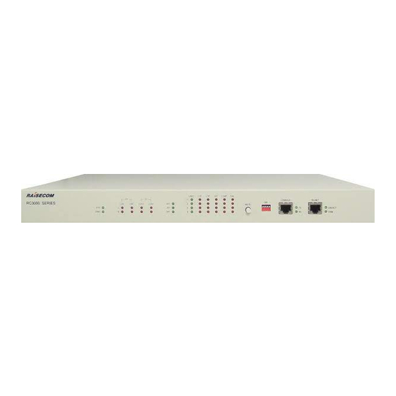
Raisecom RC3000 User Manual (105 pages)
PCM Multi-service
Brand:
Raisecom
| Category:
Multiplexer
| Size: 1.62 MB
Table of Contents
Table of Contents
4
Chapter 1 Product Overview
10
Point to Point Application Mode
10
ADM Function
11
Daisy-Chain Application
11
Point to Multi-Point Application (Star Mode)
12
Hybrid Access of Star Topology and Daisy-Chain Topology
12
Chapter 2 Type of Device and Sub-Card
14
Device Type
14
Type of Sub-Card
14
Chapter 3 Technical Specification
16
Up-Link Sub-Card
16
E1 Interface Specification
16
Optical Interface Specification
16
Ethernet Interface Specification
16
Down-Link Sub-Card
17
Sub-Card of FXS Audio User Interface (RC3000-SUB-DS)
17
Sub-Card of FXO Audio Relay Interface (RC3000-SUB-DO)
17
Sub-Card of E&M 2-Wire Audio Relay Interface (RC3000-SUB-DM2)
17
Sub-Card of E&M 4-Wire Audio Relay Interface (RC3000-SUB-DM4)
18
Sub-Card of V35 Interface (RC3000-SUB-DV35)
18
Sub-Card of V24 Interface (RC3000-SUB-DV24)
18
Sub-Card of Ethernet Interface (RC3000-SUB-DETH)
18
Sub-Card of RS232 Interface (RC3000-SUB-D232)
18
Sub-Card of RS422 Interface (RC3000-SUB-D422)
18
Sub-Card of MT Interface (RC3000-SUB-DMT)
19
Sub-Card of FXS Polarity Reversible User Interface (RC3000-SUB-DSR)
19
Sub-Card of RS485 Interface (RC3000-SUB-D485)
19
Sub-Card of Ethernet Interface (RC3000-SUB-DETHB)
19
Sub-Card of 64K of Co-Direction Data Interface (RC3000-SUB-D485)
20
Power Supply
20
Ambiance
20
Dimension of Chassis
20
Chapter 4 Structure and Indicator
21
Structure of Chassis
21
Front Panel
21
System Indicator
22
Up-Link Sub-Card Indicators
22
Optical Interface Indicator
22
E1 Line Indicator
23
Definition of Mute, DIP Switch and Interfaces
23
Rear Panel
24
Slot of User Interface Sub-Card
24
Up-Link Interface
25
Power Supply Interface
26
Chapter 5 Function and Application
27
Function and Application of RC3000 Host
27
Default Setting
27
Self-Check and Startup
27
Explanation of System Automatic Configuration in Factory Default Status
27
Clock Switch Explanation
28
Automatic Crossover Setting
28
System and Crossover Setting
29
Device Alarms
29
Network Management Channel
30
Port Definition
31
Function of RC3000-SUB-DS
32
Function of RC3000-SUB-DO
33
Function of RC3000-SUB-DSO
34
Function of RC3000-SUB-DM2
35
Function of RC3000-SUB-DM4
36
Function of RC3000-SUB-DV35
37
Rules for Channel Allocation
37
Definition of V35 Interface
38
Setting of V35 Sub-Card
39
Function of RC3000-SUB-DETH
39
Rules for Channel Allocation
39
Definition of Ethernet Interface
39
Setting of Ethernet Sub-Card
39
Function of RC3000-SUB-D232
40
Interface Reference of RS232
40
Function of RC3000-SUB-D422
41
Function of RC3000-SUB-DMT
41
Function of RC3000-SUB-DSR
42
Function of RC3000-SUB-D485
43
Function of RC3000-SUB-DSR(-48V)
44
Function of RC3000-SUB-DETHB
44
Rules for Channel Allocation
44
Definition of Ethernet Interface
44
Setting of Ethernet Sub-Card
44
Function of RC3000-SUB-Dethx2
45
Rules for Channel Allocation
45
Definition of Dual-Ethernet Interface
45
Setting of Ethernet Sub-Card
45
Function of RC3000-SUB-DV24
45
Timeslot Setting Rules
47
Function of RC3000-SUB-DC64K
47
Panel Diagram
47
Indicator Description
47
Interface Diagram
47
Definition of Interface
48
Function of RC3000-SUB-10FXS Card
48
Function of RC3000-SUB-10FXO Card
49
Function of RC3000-SUB-OPT-FE
50
Function of RC3000-SUB-OPT-2E1
51
Chapter 6 Installation and Testing
53
Unpacking Check-Up
53
Preparation before Installation
53
Installing Process
53
Fix the Device
53
Connecting Cables
53
Power on and Setting the Device
54
Chapter 7 FAQ
55
SYS Is on
55
Alarms of E1 Interface
55
Cross Connection Cannot Communicate Normally
55
There Is no Alarm but Voice Channel Is Discontinuous or Communication Is Abnormal
55
There Is LOF or RAL Alarms Sometimes of E1 Interface
56
Not All Devices in a Network Can be Network Managed
56
Device Cannot be Configured through CONSOLE
56
Memory Information Loss
56
Display of Device Is Abnormal
57
Forget the Password
57
Appendix A How to Use Hyper Terminal to Configure RC3000
58
Enter
58
Input the Password
59
Main Menu
59
Device Set Query
59
Device ID and Baud Rate
60
Line-Board Information (RAM)
60
Line-Board Information (EEPROM)
61
E1 Using and Mode Information
62
Clock, CRC and Net Information, Version Setting
62
E1 Alarm Mask Information
63
Sub-Card Information (RAM)
64
Sub-Card Information (EEPROM)
68
Cross Set Query Menu
68
Four E1 Cross Query (RAM)
69
Four User Cross Query (RAM)
69
Four E1 Cross Query (EEPROM)
70
Four User Cross Query (EEPROM)
71
State Info Query
71
Receive State Query
71
Transmit State Query
72
Alarm Query Menu
72
Device Alarm
72
System Alarm
73
Setting Menu
73
System Setting Menu
73
ID Set
74
Baud Rate Set
74
Line-Board Set
74
E1 Set
75
E1 Clock Set
76
Net Channel Set
76
Alarm Sound Set
78
User Board Set
79
DCD and CTS of V35V24 Board with Alarm Set
81
Line Board Setting Menu
81
Alarm Mask Set
81
Loopback Set
82
ALS Set
82
Ether Net Port Set
82
Ether Net Port Work Set
82
Transmit Band Width Set
83
Receive Band Width Set
83
Reset Ether Net
83
2E1 Setting Menu
83
Alarm Mask Set
84
Loopback Set
84
ALS Enable Set
84
E1 Set
85
Use Set
85
Mode Set
85
Mask Set
85
CRC Set
86
User Card Set (with Signal) Menu
86
Input Signal
86
Output Signal
86
Signal Bit
86
10-Line Mode
87
V35 User Card Setting Menu
87
Sub-Card Slot Number
87
Receive Data Phase
88
Transmit Data Phase
88
Channel Select
88
Loopback Set
88
Error Code Test
89
Auto to Adjust Phase for Transmit
89
To Adjust Receive Phase
89
V24 User Card Set
89
10Baset Ethernet Sub-Card Setting Menu
90
Sub-Board Slot Number
90
Channel Select
90
Buffer Size Set
90
Default Port Mode
90
Reset Ethernet Port
91
RS232, RS422 and RS485 Sub-Card Setting Menu
91
Channel Band Width Set
91
10/100Baset Auto-Negotiation Ethernet Sub-Card Setting Menu
91
Sub-Board Slot Number
91
Channel Select
92
Auto-Negotiation Set
92
Default Port Mode
92
Reset Ethernet Port
92
Double-Line 10/100Baset Auto-Negotiation Ethernet Sub-Card Setting Menu
92
Timeslot Set of the First Ethernet Line
93
Channel Selection of the First Ethernet Line
93
Auto-Negotiation Set of the First Ethernet Line
93
Default Port Mode of the First Ethernet Line
93
Timeslot Set of the Second Ethernet Line
93
Channel Selection of the Second Ethernet Line
94
Auto-Negotiation Set of the Second Ethernet Line
94
Default Port Mode of the First Ethernet Line
94
Reset Ethernet Port
94
DC64K Sub-Card Set
95
Alarm Mask Set
95
Port Loopback Setting
95
Error Test
95
Undefined Sub-Card Setting
96
Timeslot Setting
96
A21.2 Mode 0 Setting
96
A21.3 Mode 1 Setting
97
A21.4 Byte 1 Set
97
A21.5 Byte 2 Set
97
Cross Setting Menu
97
Cross Set
98
Create Group Cross
98
Delete Group Cross
99
REV.A Work Mode Set
100
Operate Menu
100
System Reset
101
Mute
101
Clear All Set
101
Clear Cross Set
101
Save Set Info
101
Make Default Set
102
Clear Reset and Card-Change Flag
102
Test Watchdog
102
Test EEPROM
102
Version
102
Display Version Information
102
Console Setting Menu
103
Language Select
103
Password Set
103
Quit
103
Hot Key Explanation
103
Advertisement
Raisecom RC3000 User Manual (86 pages)
PCM Multi-Service Multiplexer
Brand:
Raisecom
| Category:
Multiplexer
| Size: 0.46 MB
Table of Contents
1 Cautions
2
Table of Contents
3
2 Overview
8
Introduction
8
Main Features
8
3 Application Examples
10
Traditional PCM Application
10
Automatic ADM Application
10
Multi Devices ADM Application
11
Point-To-Multipoint Star Topology Application
12
Hybrid Access of Star Topology and Chain Topology
12
4 Device Type and User-Board Explanation
13
Device Type Explanation
13
User-Board Type Explanation
14
5 Parameters
16
Line-Board Parameters
16
E1 Interface Parameters
16
Optical Fiber Parameters
16
Ethernet Interface Parameters
17
User-Board Parameters
17
Interface Standard of FXS User-Board (RC3000-SUB-DS)
17
Interface Standard of FXO Voice Relay User-Board (RC3000-SUB-DO)
18
Interface Standard of E&M 2 Audio Relay User-Board (RC3000-SUB-DM2)
18
Interface Standard of E&M 4 Audio Relay User-Board (RC3000-SUB-DM4)
19
Standard of V35 Data User-Board (RC3000-SUB-DV35)
19
Interface Standard of V24 Data User-Board (RC3000-SUB-DV24)
19
Interface Standard of Ethernet Data User-Board (RC3000-SUB-DETH)
20
Interface Standard of RS232 Serial Data User-Board (RC3000-SUB-D232)
20
Interface Standard of RS422 Serial Data User-Board (RC3000-SUB-D422)
20
Interface Standard of Magneto Telephone User-Board (RC3000-SUB-DMT)
20
Interface Standard of FXS User-Board with Polarity Reversal Function
21
(Rc3000-Sub-Dsr)£ º
21
Power Supply
21
Environment Requirement
22
6 Structure and Indicator Lights
23
Fundamental Structure
23
Front Panel Explanation
25
Globle Indicator Lights
25
Indicator Lights of Line-Board
25
Optical Interface Alarm Indicator Lights
25
E1 Line Alarm Indicator Lights
26
Definition of Mute, DIP-Switches and Interfaces
26
Rear Panel Explanation
27
User-Board Slots
27
Line-Board Interface
28
Power Supply Interface
28
7 Function & Application
29
Function and Application Explanation of RC3000
29
Factory Default Configuration
29
Start Self-Check
29
System Automatic Configuration in Factory Default Status
29
Clock Switch Explanation
30
Auto Cross Connect Explanation
30
Explanation of System Configuration and Cross Connect Configuration
31
Alarm Explanation
31
Network Management Channel Explanation
32
Interface Definitions
33
RC3000-SUB-DS User Voice Card Explanation
35
RC3000-SUB-DO Voice Relay Card Explanation
36
RC3000-SUB-DSO User-Board Explanation
37
RC3000-SUB-DM2 Audio Relay Card Explanation
37
RC3000-SUB-DM4 Audio Relay Card Explanation
38
RC3000-SUB-DV35 User-Board Explanation
39
Rules for Channel Allocation
39
V35 Interface Definition
40
V35 Data Card Configuration Explanation
41
RC3000-SUB-DETH User-Board Explanation
42
Rules of Channel Distribution
42
Ethernet Interface Definition
42
Ethernet Data Card Configuration Explanation
42
RC3000-SUB-D232 User-Board Explanation
42
RC3000-SUB-D422 User-Board Explanation
43
RC3000-SUB-DMT User-Board Explantion
44
RC3000-SUB-DSR User-Board Explanation
45
RC3000-SUB-OPT-FE Explanation
46
RC3000-SUB-OPT-2E1 Explanation
46
8 Installation & Verifying
48
Check When You First Open the Box
48
Preparation before Installation
48
Installation
48
Device Fixing
48
Cabble Connection
48
Powered on
49
9 Q & a
50
SYS Is on
50
Alarms of E1 Interface
50
Faq
50
Cross Connection Cannot Communicate Normally
50
Abnormal
51
There Is LOF or RAL Alarms Sometimes of E1 Inteface
51
Not All Devices in a Network Can be Network Managed
51
Device Cannot be Configured through CONSOLE
52
Memory Information Loss
52
Display of Device Is Abnormal
52
Forget the Password
52
10 Appendix A: How to Use Hyper Terminal to Configure RC3000
53
Enter
53
Input the Password
54
Main Menu
55
Device Set Query
55
Device ID and Baud Rate
55
Line-Board Information (RAM)
56
Line-Board Information (EEPROM)
56
E1 Using and Mode Information
57
Clock, CRC and Net Information
57
E1 Alarm Mask Information
58
User-Board Information (RAM)
58
User-Board Information (EEPROM)
60
Cross Set Query Menu
60
Four E1 Cross Query(RAM)
60
Four User Cross Query (RAM)
61
Four E1 Cross Query (EEPROM)
61
Four User Cross Query (EEPROM)
62
State Info Query
62
Receive State Query
63
Transmit State Query
63
Alarm Query Menu
63
Device Alarm
63
System Alarm
64
Set Menu
64
System Set Menu
64
ID Set
65
Baud Rate Set
65
Line-Board Set
65
E1 Set
66
E1 Clock Set
66
Net Topology Set
66
Alarm Sound Set
69
User Board Set
69
DCD and RTS of V35V24 Board with Alarm Set
70
Line Board Set Menu
70
Alarm Mask Set
71
Loopback Set
71
ALS Set
71
Ether Net Port Set
71
Ether Net Port Work Set
72
Transmit Band Width Set
72
Receive Band Width Set
72
Reset Ether Net
72
E1 Set
73
Use Set
73
Mode Set
73
Mask Set
73
CRC Set
74
User Board Set (with Signal) Menu
74
Input Signal
74
Output Signal
74
Signal Bit
75
V35 User Board Set Menu
75
Sub-Board Slot Number
75
Receive Data Phase
76
Transmit Data Phase
76
Channel Select
76
Loopback Set
77
Error Code Test
77
Auto to Adjust Phase for Transmit
77
To Adjust Receive Phase
77
Ethernet User-Board Set Menu
78
Sub-Board Slot Number
78
Channel Select
78
Buffer Size Set
78
Default Port Mode
79
Reset Ether Net Port
79
RS232 and RS422 User-Board Set Menu
79
Channel Band Width Set
79
Cross Set Menu
79
Cross Set
80
Create Group Cross
80
Delete Group Cross
81
Operate Menu
82
System Reset
82
Mute
82
Clear All Set
82
Clear Cross Set
83
Save Set Info
83
Make Default Set
83
Clear Reset and Board-Change Flag
83
Test Watchdog
83
Test EEPROM
83
Version
84
Display Version Information
84
Console Set Menu
84
Language Select
84
Password Set
84
Quit
85
Hot Key Explanation
85
Advertisement
Related Products
Raisecom RC3000 PCM
Raisecom RC3000E
Raisecom RC3000-15
Raisecom RC801
Raisecom RC805-240B
Raisecom RC831-120-S3
Raisecom RC805-120B-S1
Raisecom RC805-120B-S2
Raisecom Technology RC806-60B-S1
Raisecom Technology RC804-60B-S1
Raisecom Categories
Multiplexer
Switch
Network Hardware
Media Converter
Network Router
More Raisecom Manuals
Login
Sign In
OR
Sign in with Facebook
Sign in with Google
Upload manual
Upload from disk
Upload from URL