OMRON ZFV-C Manuals
Manuals and User Guides for OMRON ZFV-C. We have 5 OMRON ZFV-C manuals available for free PDF download: User Manual, Manual, Command Reference Manual, Specification

Omron ZFV-C User Manual (166 pages)
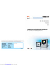
Smart Sensors with Ultra-High-Speed Color CCD Cameras
Brand: Omron
|
Category: Security System
|
Size: 7 MB
Table of Contents
Advertisement

OMRON ZFV-C Manual (162 pages)
Smart Sensor with Ultra-High-Speed Color CCD Cameras
Brand: OMRON
|
Category: Security Camera
|
Size: 4 MB
Table of Contents

Omron ZFV-C Command Reference Manual (29 pages)
CompoWay/F Communication
Brand: Omron
|
Category: Accessories
|
Size: 0 MB
Table of Contents
Advertisement

Omron ZFV-C Command Reference Manual (22 pages)
Smart Sensor, Non-procedural Communication
Brand: Omron
|
Category: Accessories
|
Size: 0 MB
Table of Contents
Omron ZFV-C Specification (8 pages)
Smart Sensors with Ultra-High-Speed Color CCD Cameras
Brand: Omron
|
Category: Transmitter
|
Size: 0 MB
Advertisement