Omron CJ Series Manuals
Manuals and User Guides for Omron CJ Series. We have 18 Omron CJ Series manuals available for free PDF download: Operation Manual, Operator's Manual, Connection Manual, Manual
Advertisement
Omron CJ Series Operation Manual (304 pages)
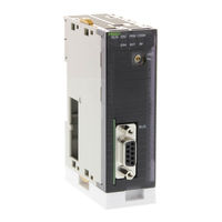
Master Unit
Brand: Omron
|
Category: Control Unit
|
Size: 3 MB
Table of Contents
Omron CJ Series Operation Manual (290 pages)
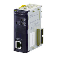
Ethernet Units Construction of Networks
Brand: Omron
|
Category: Network Hardware
|
Size: 4 MB
Table of Contents
Advertisement
Omron CJ Series Operator's Manual (274 pages)
CX-Simulator
Brand: Omron
|
Category: Controller
|
Size: 1 MB
Table of Contents
Omron CJ Series Operation Manual (278 pages)
Machine Automation Controller
Brand: Omron
|
Category: Controller
|
Size: 3 MB
Table of Contents
Omron CJ Series Operation Manual (184 pages)
Machine Automation Controller Analog I/O Units
Brand: Omron
|
Category: I/O Systems
|
Size: 1 MB
Table of Contents
Omron CJ Series Operation Manual (181 pages)
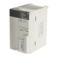
Built-in I/O. CPU Units
Brand: Omron
|
Category: Controller
|
Size: 2 MB
Table of Contents
Omron CJ Series Operation Manual (117 pages)
Sysmac Temperature Control Units
Brand: Omron
|
Category: Temperature Controller
|
Size: 1 MB
Table of Contents
Omron CJ Series Connection Manual (96 pages)
General-purpose Ethernet Connection Guide (TCP/IP) for Yamaha Motor RCX Robot Controller
Brand: Omron
|
Category: Controller
|
Size: 2 MB
Table of Contents
Omron CJ Series Connection Manual (82 pages)
General-purpose Serial (RS-232C), Corporation Displacement Sensor
Brand: Omron
|
Category: Controller
|
Size: 2 MB
Table of Contents

Omron CJ Series Connection Manual (78 pages)
Brand: Omron
|
Category: Controller
|
Size: 4 MB
Table of Contents

Omron CJ Series Connection Manual (64 pages)
General-purpose Serial, RS-485 Modbus Communication, Multi-function Compact Inverter
Table of Contents
Omron CJ Series Connection Manual (64 pages)
General-purpose Serial Connection Guide for Oriental Motor Brushless Motor and Driver Package BLE
Brand: Omron
|
Category: Controller
|
Size: 2 MB
Table of Contents

Omron CJ Series Connection Manual (54 pages)
EtherNet/IP Coupler Unit
Brand: Omron
|
Category: Network Hardware
|
Size: 3 MB
Table of Contents
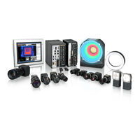
Omron CJ Series Connection Manual (54 pages)
CJ Series EtherNet/IP
Brand: Omron
|
Category: Machine Vision Systems
|
Size: 2 MB
Table of Contents
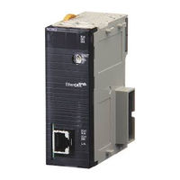
OMRON CJ Series Connection Manual (36 pages)
CJ Series
EtherCAT
Digital Sensor Communication Unit
Brand: OMRON
|
Category: Accessories
|
Size: 2 MB
Table of Contents

Omron CJ Series Manual (38 pages)
HOST Link Driver
Brand: Omron
|
Category: Controller
|
Size: 0 MB
Table of Contents
Omron CJ Series Connection Manual (20 pages)
EtherNet/IP Vision System
Brand: Omron
|
Category: Computer Hardware
|
Size: 0 MB
Table of Contents
Advertisement