Omron CJ Series Operation Manual
Machine automation controller analog i/o units
Hide thumbs
Also See for CJ Series:
- Operation manual (304 pages) ,
- Connection manual (96 pages) ,
- Manual (38 pages)

Related Manuals for Omron CJ Series


Summary of Contents for Omron CJ Series
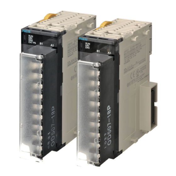
- Page 1 Machine Automation Controller CJ-series Analog I/O Units Operation Manual for NJ-series CPU Unit CJ1W-PDC15 CJ1W-PH41U CJ1W-AD04U Analog I/O Units W498-E1-03...
- Page 2 OMRON. No patent liability is assumed with respect to the use of the information contained herein. Moreover, because OMRON is constantly striving to improve its high-quality products, the information contained in this manual is subject to change without notice.
-
Page 3: Introduction
Introduction Introduction Thank you for purchasing an CJ-series Analog I/O Units . This manual contains information that is necessary to use with the NJ-series CPU Unit. Please read this manual and make sure you understand the functionality and performance of the NJ-series CPU Unit before you attempt to use it in a control system. -
Page 4: Relevant Manuals
Relevant Manuals Relevant Manuals There are three manuals that provide basic information on the NJ-series CPU Units: the NJ-series CPU Unit Hardware User’s Manual, the NJ-series CPU Unit Software User’s Manual, and the NJ-series Instructions Reference Manual. Most operations are performed from the Sysmac Studio Automation Software. Refer to the Sysmac Studio Version 1 Operation Manual (Cat. -
Page 5: Manual Configuration
Manual Configuration Manual Configuration NJ-series CPU Unit Hardware User’s Manual (Cat. No. W500) Section Description Section 1 This section provides an introduction to the NJ-series Controllers and their features, Introduction and gives the NJ-series Controller specifications. Section 2 This section describes the system configuration used for NJ-series Controllers. System Configuration Section 3 This section describes the parts and functions of the configuration devices in the NJ-... - Page 6 Units (CJ1W-AD04U/PH41U), and describes the operating procedure and how to Input Units wire the Unit. Appendices CJ Series Analog I/O Unit Operation Manual (Cat. No. W368) Section Description This section presents an overview of the CS/CJ-series Analog I/O Units and outlines Section 1 Overview and Feature their features.
-
Page 7: Manual Structure
Manual Structure Manual Structure Page Structure The following page structure is used in this manual. Level 1 heading 4 Installation and Wiring Level 2 heading Mounting Units Level 3 heading Level 2 heading Gives the current headings. Level 3 heading 4-3-1 Connecting Controller Components The Units that make up an NJ-series Controller can be connected simply by pressing the Units together... - Page 8 Manual Structure Precaution on Terminology In this manual, “download” refers to transferring data from the Sysmac Studio to the physical Controller and “upload” refers to transferring data from the physical Controller to the Sysmac Studio. For the Sysmac Studio, synchronization is used to both upload and download data. Here, “synchronize” means to automatically compare the data for the Sysmac Studio on the computer with the data in the physical Controller and transfer the data in the direction that is specified by the user.
-
Page 9: Sections In This Manual
Sections in this Manual Sections in this Manual Overview and Features Isolated-type Direct Current Input Unit Isolated-type Universal Input Units Appendices Index CJ-series Analog I/O Units Operation Manual for NJ-series CPU Unit(W498) -
Page 10: Table Of Contents
CONTENTS CONTENTS Introduction ....................... 1 Relevant Manuals ...................... 2 Manual Configuration ....................3 Manual Structure ....................... 5 Sections in this Manual .................... 7 CONTENTS......................... 8 Read and Understand this Manual ................ 11 Safety Precautions ....................14 Precautions for Safe Use..................19 Precautions for Correct Use................... -
Page 11: Contents
CONTENTS Specifications and Installation ..................... 1-19 1-4-1 Specifications..........................1-19 1-4-2 Nomenclature and Functions....................1-20 Mounting the Units ........................ 1-23 1-5-1 Mounting the Units (Common)....................1-23 1-5-2 Precautions when Handling Units..................... 1-25 1-5-3 Connecting Crimp Terminals ....................1-26 1-5-4 Dimensions ..........................1-26 Exchanging Data with the CPU Unit .................. - Page 12 CONTENTS CJ1W-PH41U Isolated-type Universal Input Unit ..............3-14 3-2-1 Overview ........................... 3-14 3-2-2 System Configuration........................ 3-14 3-2-3 Features ............................ 3-15 3-2-4 Model Information ........................3-15 3-2-5 Block Diagram (Order of Processing) ..................3-16 3-2-6 Specifications ..........................3-17 3-2-7 Setting Parameters (Device Variables for CJ-series Unit)............3-25 3-2-8 Operation Data (Device Variables for CJ-series Unit) ...............
-
Page 13: Read And Understand This Manual
WHETHER SUCH CLAIM IS BASED ON CONTRACT, WARRANTY, NEGLIGENCE, OR STRICT LIABILITY. In no event shall the responsibility of OMRON for any act exceed the individual price of the product on which liability is asserted. IN NO EVENT SHALL OMRON BE RESPONSIBLE FOR WARRANTY, REPAIR, OR OTHER CLAIMS... - Page 14 Application Considerations SUITABILITY FOR USE OMRON shall not be responsible for conformity with any standards, codes, or regulations that apply to the combination of products in the customer's application or use of the products. At the customer's request, OMRON will provide applicable third party certification documents identifying ratings and limitations of use that apply to the products.
- Page 15 Performance data given in this manual is provided as a guide for the user in determining suitability and does not constitute a warranty. It may represent the result of OMRON's test conditions, and the users must correlate it to actual application requirements. Actual performance is subject to the OMRON Warranty and Limitations of Liability.
-
Page 16: Safety Precautions
Safety Precautions Safety Precautions Definition of Precautionary Information The following notation is used in this manual to provide precautions required to ensure safe usage of a CJ-series Analog I/O Unit. The safety precautions that are provided are extremely important to safety. Always read and heed the information provided in all safety precautions. - Page 17 Safety Precautions Symbols The circle and slash symbol indicates operations that you must not do. The specific operation is shown in the circle and explained in text. This example indicates prohibiting disassembly. The triangle symbol indicates precautions (including warnings). The specific operation is shown in the triangle and explained in text. This example indicates a precaution for electric shock.
- Page 18 Safety Precautions WARNING During Power Supply Do not touch any of the terminals or terminal blocks while the power is being supplied. Doing so may result in electric shock. Do not attempt to take any Unit apart. In particular, high-voltage parts are present in the Power Supply Unit while power is supplied or immediately after power is turned OFF.
- Page 19 Safety Precautions WARNING Fail-safe Measures Unintended outputs may occur when an error occurs in variable memory or in memory used for CJ-series Units. As a countermeasure for such prob- lems, external safety measures must be provided to ensure safe operation of the system.
- Page 20 Safety Precautions Caution Application Do not touch any Unit when power is being supplied or immediately after the power supply is turned OFF. Doing so may result in burn injury. Wiring Be sure that all terminal screws and cable connector screws are tightened to the torque specified in the relevant manuals.
-
Page 21: Precautions For Safe Use
Precautions for Safe Use Precautions for Safe Use Disassembly and Dropping • Do not attempt to disassemble, repair, or modify any Units. Doing so may result in malfunction or fire. • Do not drop any Unit or subject it to abnormal vibration or shock. Doing so may result in Unit malfunc- tion or burning. - Page 22 Precautions for Safe Use • Do not apply voltages or connect loads to the Output Units or slaves in excess of the maximum rat- ings. • Surge current occurs when the power supply is turned ON. When selecting fuses or breakers for external circuits, consider the above precaution and allow sufficient margin in shut-off performance.
- Page 23 Precautions for Safe Use • Connecting cables or wiring the system • Connecting or disconnecting the connectors The Power Supply Unit may continue to supply power to the rest of the Controller for a few seconds after the power supply turns OFF. The PWR indicator is lit during this time. Confirm that the PWR indicator is not lit before you perform any of the above.
- Page 24 CAT slaves are cut off. During that period, the slave outputs behave according to the slave settings. The time that communications are cut off depends on the EtherCAT network configuration. If the EtherCAT network configuration contains only OMRON EtherCAT slaves, communications are cut off for a maximum of 45 seconds.
- Page 25 Precautions for Safe Use • If the Fail-soft Operation parameter is set to stop operation, process data communications will stop for all slaves when an EtherCAT communications error is detected in a slave. For this reason, if Servo Drives are connected, the Servos for all axes will be turned OFF. Make sure that the Fail-soft Operation parameter setting results in safe operation when a device error occurs.
- Page 26 Precautions for Safe Use • Apply power for at least five minutes before changing the Battery. Install a new Battery within five minutes (at 25°C) of turning OFF the power supply. If power is not supplied for at least 5 minutes, the saved data may be lost.
-
Page 27: Precautions For Correct Use
Precautions for Correct Use Precautions for Correct Use Storage, Mounting, and Wiring • Do not operate or store the Controller in the following locations. Operation may stop or malfunctions may occur. • Locations subject to direct sunlight • Locations subject to temperatures or humidity outside the range specified in the specifications •... - Page 28 Precautions for Correct Use Error Processing • In applications that use the results of instructions that read the error status, consider the affect on the system when errors are detected and program error processing accordingly. For example, even the detection of a minor error, such as Battery replacement during operation, can affect the system depending on how the user program is written.
- Page 29 Precautions for Correct Use Battery Replacement • Be sure to install a replacement Battery within two years of the production date shown on the Battery label. • Turn ON the power after replacing the Battery for a CPU Unit that has been unused for a long time. Leaving the CPU Unit unused again without turning ON the power even once after the Battery is replaced may result in a shorter Battery life.
- Page 30 Precautions for Correct Use SD Memory Cards • Insert the SD Memory Card all the way. • Do not turn OFF the power supply to the Controller during SD Memory Card access. The files may be corrupted. If there is a corrupted file in the SD Memory Card, the file is automatically deleted by the restoration function when the power supply is turned ON.
-
Page 31: Regulations And Standards
Concepts EMC Directive OMRON devices that comply with EC Directives also conform to the related EMC standards so that they can be more easily built into other devices or the overall machine. The actual products have been checked for conformity to EMC standards.* Whether the products conform to the standards in the system used by the customer, however, must be checked by the customer. - Page 32 The NJ-series Controllers comply with the following shipbuilding standards. Applicability to the ship- building standards is based on certain usage conditions. It may not be possible to use the product in some locations. Contact your OMRON representative before attempting to use a Controller on a ship.
-
Page 33: Unit Versions
Gives the lot number and serial number of the Unit. serial number DDMYY: Lot number, @: For use by OMRON, xxxx: Serial number “M” gives the month (1 to 9: January to September, X: October, Y: November, Z: December) MAC address Gives the MAC address of the built-in port on the Unit. - Page 34 Unit Versions Right-click any open space in the Unit Editor and select Production Information. The Production Information Dialog Box is displayed. Simple Display Detailed Display In this example, “Ver.1.00” is displayed next to the unit model. The following items are displayed. CPU Unit CJ-series Units Unit model...
-
Page 35: Related Manuals
Related Manuals Related Manuals The following manuals are related to the NJ-series Controllers. Use these manuals for reference. Manual name Cat. No. Model numbers Application Description NJ-series CPU Unit W500 NJ501-@@@@ Learning the basic specifi- An introduction to the entire NJ-series system is Hardware User’s Manual NJ301-@@@@ cations of the NJ-series... -
Page 36: Revision History
Revision History Revision History A manual revision code appears as a suffix to the catalog number on the front and back covers of the manual. W498-E1-03 Cat. No. Revision code Revision code Date Revised content July 2011 Original production March 2012 Corrected errors. -
Page 37: Overview And Features
Overview and Features This section presents an overview of the CJ-series Analog I/O Units and outlines their features. 1-1 Overview of Analog I/O Units ........1-3 1-2 Features and Functions . - Page 38 1 Overview and Features 1-6 Exchanging Data with the CPU Unit ......1-27 1-6-1 Exchanging Data with the CPU Unit .
-
Page 39: Overview Of Analog I/O Units
1 Overview and Features Overview of Analog I/O Units The CJ Series includes two types of Analog I/O Units available in three models as shown in the follow- ing table. Name Model I/O type Num- Resolu- Conver- Field I/O Main functions... - Page 40 1 Overview and Features Name Model I/O type Num- Resolu- Conver- Field I/O Main functions ber of tion sion isolation cycle Isolated- CJ1W- • Resistance 4 inputs 1/12,000 250 ms/ All inputs are • Process value scaling type Uni- AD04U thermometer: 4 inputs isolated.
-
Page 41: Features And Functions
1 Overview and Features Features and Functions 1-2-1 Isolation between Channels The Analog I/O Units listed below have isolation between inputs. Therefore sneak circuits do not occur between thermocouples or between the power supply's common voltage inputs, so there is no need to utilize a signal converter to prevent sneak circuits. -
Page 42: Process Value Scaling To Industrial Units
1 Overview and Features 1-2-3 Process Value Scaling to Industrial Units This function takes the value scaled to industrial units with respect to the input signal's zero point and span point, and outputs it to the CPU Unit as the process value. Because of this, no user program is required at the CPU Unit for scaling. -
Page 43: Offset Compensation
1 Overview and Features 1-2-4 Offset Compensation Offset compensation is possible for process value errors. The amount of the error is added to the pro- cess value. Applicable Units Isolated-type Universal Input Unit CJ1W-PH41U Upper limit (2147483647) Scaling upper limit Scaling offset value Scaling lower limit... -
Page 44: Rate-Of-Change Calculation And Alarm
1 Overview and Features 1-2-6 Rate-of-change Calculation and Alarm The Analog I/O Units listed below calculate the rate of change for the process value, and output an alarm when the high or low limit is exceeded. The rate-of-change value is derived by taking the differ- ence each second between the process value at that time and the process value before the comparison time interval *1. -
Page 45: Alarm Hysteresis
1 Overview and Features 1-2-7 Alarm Hysteresis An hysteresis can be set for the process value alarm and the rate-of-change alarm. The operation is as shown in the following diagram. Applicable Units Isolated-type Direct Current Input Unit CJ1W-PDC15 Isolated-type Universal Input Units CJ1W-AD04U CJ1W-PH41U Hysteresis... -
Page 46: Mean Value Processing
1 Overview and Features OFF-delay Outputs This function makes it possible to turn OFF the alarm signal after a set time period (0 to 60 s) has elapsed after alarm status is cleared, rather than having the alarm turned OFF immediately. An alarm OFF-delay time can be set for each input. -
Page 47: Input Disconnection Detected
1 Overview and Features 1-2-10 Input Disconnection Detected Sensor disconnections can be detected for thermocouple input and resistance thermometer input. When a disconnection occurs, Input Error in the Operation Data becomes 1. Either the high (115%) or low (−15%) direction can be specified for when a disconnection is detected. Applicable Units Isolated-type Universal Input Units CJ1W-AD04U... -
Page 48: Cold Junction Sensor Errors Detection
1 Overview and Features 1-2-12 Cold Junction Sensor Errors Detection If a Universal Input Unit cold junction sensor is disconnected, if a short-circuit occurs, or if an error occurs at the cold junction sensor, Cold Junction Sensor Error in the Operation Data is set to 1 and the temperature process value with no cold junction compensation is stored. - Page 49 1 Overview and Features Zero/Span Adjustment Only Applicable Units Isolated-type Universal Input Unit CJ1W-AD04U Zero/Span Adjustment and Zero/Span Adjustment for Specified Points Applicable Units Isolated-type Analog Input Unit CJ1W-PDC15 Isolated-type Universal Input Unit CJ1W-PH41U CPU Unit Analog I/O Unit Zero/Span Adjustment Output data Setting Parameters Maximum range...
-
Page 50: Adjustment Period Control
1 Overview and Features 1-2-15 Adjustment Period Control When zero/span adjustment is executed and the Adjustment Update Bit is set, the date is internally recorded at the Unit. When the preset Zero/Span Adjustment Period End and Notice of Days Remaining in the expansion setting parameters have elapsed, this function turns ON a warning flag to give notice that it is time for readjustment. -
Page 51: Peak And Bottom Detection
1 Overview and Features 1-2-16 Peak and Bottom Detection This function detects the peak (maximum) and bottom (minimum) process values. This function detects the maximum and minimum analog input values, from when the Hold Start in the Expansion Operation Data turns ON until it turns OFF. The "Peak/Top Value"... -
Page 52: Top And Valley Detection
1 Overview and Features 1-2-17 Top and Valley Detection This function detects the top and valley values of the process value. This function detects the top and valley input values from when the Hold Start in the Expansion Opera- tion Data turns ON until it turns OFF. A detection hysteresis can be set so that minute changes are not detected. -
Page 53: Integral Value Calculation
1 Overview and Features 1-2-18 Integral Value Calculation This function calculates the integral of the process value over time. The unit can be selected as either "hour" or "minute" with the Integer Unit setting in the Expansion Set- ting Parameters. The integral value can be output to "Integral Value"... -
Page 54: System Configuration
1 Overview and Features System Configuration These Analog I/O Units belong to the NJ-series CJ Special I/O Unit group. You can mount them to NJ- series CPU Racks or Expansion Racks. The number of Units that you can mount to one Rack (either a CPU Rack or an Expansion Rack) depends upon the maximum current supplied by the Power Supply Unit and the current consumption by the other Units. -
Page 55: Specifications And Installation
1 Overview and Features Specifications and Installation 1-4-1 Specifications The specifications shown in the following table apply to all the Analog I/O Units. For specifications specific to each Unit, refer to 2-1-6 Specifications for CJ1W-PDC15, 3-1-6 Specifica- tions for CJ1W-AD04U, and 3-2-6 Specifications for CJ1W-PH41U. Item Specification Unit classification... -
Page 56: Nomenclature And Functions
1 Overview and Features 1-4-2 Nomenclature and Functions Slider Indicators PH41U MACH Unit number switch Expansion connector Terminal block Terminal-block lock lever Slider (When the lever is lowered, the lever releases the lock.) DIN track mounting pins CJ1W-PDC15 EXT PS Indicator Meaning Status... - Page 57 1 Overview and Features CJ1W-AD04U Indicator Meaning Status Operating status RUN (green) Operating Operating normally. Not lit Unit has stopped exchanging data with the CPU Unit. ERC (red) Error detected Data setting is out of range in a parameter or Input Error by Unit has occurred.
- Page 58 1 Overview and Features Unit Number Switches Use the unit number switches to set the specific unit number for each Special I/O Unit mounted in a CPU Rack or Expansion Rack. The unit number must be the one registered in the Unit Configura- tion.
-
Page 59: Mounting The Units
1 Overview and Features Mounting the Units Precautions for Correct Use Precautions for Correct Use • Do not connect a Relay Output Unit (CJ1W-OC@@@) to a CPU Rack or Expansion Rack when using the CJ1W-PH41U. Because the CJ1W-PH41U measures at high resolution, there is possibility of normal measurement being impossible due to noise generated during relay out- put switching. - Page 60 1 Overview and Features Move the sliders on the top and bottom of the Unit to the lock position to secure the Units. The sliders should click into place. Move the sliders to the back until they click into place. Slider Lock Release...
-
Page 61: Precautions When Handling Units
1 Overview and Features 1-5-2 Precautions when Handling Units • Be sure to turn OFF the power supply to the Controller before Units or connecting lines are installed or disconnected. • To reduce the risk of malfunctioning due to electrical noise, wire input and output lines in separate ducts from high-voltage and power lines. -
Page 62: Connecting Crimp Terminals
1 Overview and Features 1-5-3 Connecting Crimp Terminals M3 screw Fork type Round type 6.0 mm max. 6.0 mm max. Precautions for Correct Use Precautions for Correct Use Tighten the terminal screws securely to a torque of 0.5 N·m. Loose screws may result in conver- sion errors. -
Page 63: Exchanging Data With The Cpu Unit
1 Overview and Features Exchanging Data with the CPU Unit 1-6-1 Exchanging Data with the CPU Unit Overview of Data Exchange The CPU Unit and Analog I/O Unit exchange data, such as Operation Data and initial settings parameters, via I/O ports created for Analog I/O Units or as necessary via the memory used for CJ- series Units. - Page 64 1 Overview and Features When a device variable name for CJ-series Unit is assigned with method 2 or 3, the variable input by Sysmac Studio is automatically registered in the variable table. The following is the configuration of variable names created with method 3. Device variable (name) for CJ-series Unit *_ Ch1_L_PVAlmSta This is an I/O port name.
-
Page 65: Cj1W-Pdc15
1 Overview and Features Create user-defined variables in Sysmac Studio's variable table by using the structures defined for Expansion Setting Parameters of each Unit. Assign to these variables, via AT specification, the addresses of memory used for CJ-series Unit for Expansion Setting Parameters specified in The names of variables used in the user program are listed below. - Page 66 1 Overview and Features Parameter/data AT specification Setting method Operation Data I/O port Creates automatically when the unit is registered to the unit configuration. Expansion Operation Data Memory used for Set the allocated address with one of the following methods. CJ-series Unit (After this setting, reset the Controller or restart the unit.) 1.
- Page 67 1 Overview and Features NJ-series CPU Unit CJ1W-PDC15 User program Operation Data I/O port Process value Operation Data I/O refresh Rate of change Device variables (Automatic creation Alarm output, for CJ-series Unit specification with unit registration) etc. Expansion Operation Data Memory used for CJ-series Unit Hold instruction Expansion Operation...
- Page 68 1 Overview and Features The following functions are available with respect to Setting Parameters and Operation Data of the CJ1W-PDC15. Operation Data The data is continuously refreshed. The following types of data are output: Values scaled to industrial units for process values and rate-of-change values, alarm contact data, Input Error Flag, etc.
-
Page 69: Cj1W-Ad04U
1 Overview and Features Address of Data Range Error will be 100 or greater. (The value will be 100 if the first word of the Expansion Set- ting Parameters is erroneous.) For the correspondence between range error addresses and setting parameter or expansion setting parameter addresses, refer to A-3 Correspondence Table of Analog I/O Unit Variables and CJ-series CPU Addresses. - Page 70 1 Overview and Features NJ-series CPU Unit CJ1W-AD04U User program Operation Data I/O port Process value Operation Data Alarm output, I/O refresh Device variables (Automatic creation etc. specification for CJ-series Unit with unit registration) Expansion Operation Memory used for CJ-series Unit Data Expansion Operation Data...
- Page 71 1 Overview and Features The following functions are available with respect to Setting Parameters and Operation Data of the CJ1W-AD04U. Operation Data The data for operation is continuously refreshed. The following types of data are output: Values scaled to industrial units for process values alarm contact data, Input Error Flag, etc. Expansion Opera- The data is continuously refreshed.
-
Page 72: Cj1W-Ph41U
1 Overview and Features Unit Restart To restart the Unit after the Initial Settings Parameters are changed or an error is corrected, restart the Unit with the following methods. The changes in the Initial Settings Parameters are reflected after restart. •... - Page 73 1 Overview and Features NJ-series CPU Unit CJ1W-PH41U User program Operation Data I/O port Process value Operation Data I/O refresh Rate of change Device variables (Automatic creation Alarm output, for CJ-series Unit specification with unit registration) etc. Expansion Operation Data Memory used for CJ-series Unit Hold instruction Expansion Operation...
- Page 74 1 Overview and Features The following functions are available with respect to Setting Parameters and Operation Data of the CJ1W-PH41U. Operation Data The data is continuously refreshed. The following types of data are output: Values scaled to industrial units for process values alarm contact data, Input Error Flag, etc.
- Page 75 1 Overview and Features * The ERC indicator on the Unit's front panel will light if an out-of-range setting is made in either Setting Parameter Group 1 (Continuously Refreshed Parameters) or Setting Parameter Group 2 (Initial Settings Parameters). The offset (the number of words) from the start address to the lowest address that has the range error will be out- put in the Address of Data Range Error.
-
Page 76: Operating Procedures
1 Overview and Features Operating Procedures Use the following procedures to operate the Analog I/O Unit. The procedures are the same for all mod- els. Initial Setup (Hardware) Set the unit number by using the rotary switches on the front panel of the Unit. Set the same number as in the Unit Configuration settings. - Page 77 1 Overview and Features Initial Software Setup Use Sysmac Studio to create and set programs. For operations of Sysmac Studio, refer to the Sysmac Studio Version 1 Operation Manual (Cat. No. W504). Create the Unit Configuration. Create it on the CPU/Expansion Racks screen in Configurations and Setup of Sysmac Studio. At this time, set both the device name and the unit number of the unit to be registered.
-
Page 78: Error Processing
1 Overview and Features Error Processing The following table shows the meanings of the indicator displays of the Analog I/O Unit. The contents shown here are the same for all models. For error processing specific to each Unit, refer to 2-1-13 Error Processing for CJ1W-PDC15, 3-1-12 Error Processing for CJ1W-AD04U, and 3-2-13 Error Processing for CJ1W-PH41U. - Page 79 1 Overview and Features Device variable for CJ- Processing Result Indicators on Unit series Unit *_CfgErrAdr When the Controller is The Unit will not start up. ERC indicator is lit. The offset value from the reset or the Unit is RUN indicator is not lit.
-
Page 80: Errors Related To The Cpu Unit
1 Overview and Features 1-8-2 Errors Related to the CPU Unit Meaning Probable cause Error type Detailed cause Unit status Remedy Indi- Indica- cator (red) (green) Error in data During normal I/O bus check A data transmission Conversion data Turn OFF the power exchange operation, an I/O error... -
Page 81: Event Logs
1 Overview and Features 1-8-3 Event Logs Overview of the Event Logs You use the same methods to manage all of the events that occur on the NJ-series Controller. (The events include errors and information.) You can use the Sysmac Studio or an NS-series PT to confirm current Controller events and the logs of events that have occurred. - Page 82 1 Overview and Features Error Table The errors that may occur for this Unit are listed below. The following abbreviations and symbols are used in the event level column. Abbreviation Name Major fault level Partial fault level Minor fault level Observation Info Information...
- Page 83 1 Overview and Features Error Descriptions This section describes the information that is given for individual errors. Controller Error Descriptions The items that are used to describe individual errors (events) are described in the following copy of an error table. Event name Gives the name of the error.
- Page 84 1 Overview and Features Error Descriptions Event name A/D Conversion Error Event code 0460 0000 hex Meaning An error occurred in A/D conversion. Source PLC Function Module Source details CJ-series Unit Detection Continuously timing Error attributes Level Minor fault Recovery Cycle the power Log category System...
- Page 85 1 Overview and Features Event name Non-volatile Memory Error Event code 04620000 hex Meaning An error occurred in non-volatile memory. Source PLC Function Module Source details CJ-series Unit Detection Continuously timing Error attributes Level Minor fault Recovery Cycle the power Log category System supply.
- Page 86 1 Overview and Features Event name Input Error Event code 647A 0000 hex Meaning An input error occurred. Source PLC Function Module Source details CJ-series Unit Detection Continuously timing Error attributes Level Minor fault Recovery Error reset Log category System Effects User program Continues.
- Page 87 1 Overview and Features Event name Zero/Span Adjustment Period Notice Event code 647E0000 hex Meaning The zero/span adjustment period is close to expiring. Source PLC Function Module Source details CJ-series Unit Detection Continuously timing Error attributes Level Observation Recovery Log category System Effects User program...
- Page 88 1 Overview and Features 1-52 CJ-series Analog I/O Units Operation Manual for NJ-series CPU Unit(W498)
-
Page 89: Isolated-Type Direct Current Input Unit
Isolated-type Direct Current Input Unit This section describes each of the CJ-series Isolated-type Direct Current Input Units in detail. 2-1 CJ1W-PDC15 Isolated-type Direct Current Input Unit ....2-2 2-1-1 Overview . -
Page 90: Cj1W-Pdc15 Isolated-Type Direct Current Input Unit
2 Isolated-type Direct Current Input Unit CJ1W-PDC15 Isolated-type Direct Current Input Unit 2-1-1 Overview The CJ1W-PDC15 Isolated-type Direct Current Input Unit provides two direct-current inputs. All inputs are isolated. CJ1W-PDC15 P D C R U N E R C E R H E X T M A C N o . -
Page 91: Features
2 Isolated-type Direct Current Input Unit 2-1-3 Features • Up to two DC inputs can be made to each Unit. 4 to 20 mA, 0 to 20 mA, 0 to 10 V, −10 to 10 V, 0 to 5 V, −5 to 5 V, 1 to 5 V, 0 to 1.25 V, or −1.25 to 1.25 V can be selected separately for each input. -
Page 92: Block Diagram (Order Of Processing)
2 Isolated-type Direct Current Input Unit 2-1-5 Block Diagram (Order of Processing) CPU Unit Expansion Operation Data Peak/Bottom value Top/valley value Operation Data HH, H, L, LL H, L Process value Process value alarm Rate-of-change value Rate-of-change alarm Input error Isolated-type Direct Current Input Unit Process value alarm Output limit: −15% to +115%... -
Page 93: Specifications
2 Isolated-type Direct Current Input Unit 2-1-6 Specifications Item Specifications Model CJ1W-PDC15 Applicable PLC NJ Series Unit classification CJ-series Special I/O Unit Mounting position NJ-series CPU Rack, Expansion Rack Maximum number of Units 40 (within the allowable current consumption and power consumption range) Unit numbers 00 to 95 (Cannot duplicate Special I/O Unit numbers.) Areas for data... - Page 94 2 Isolated-type Direct Current Input Unit Item Specifications Maximum time to store data in CPU Conversion cycle + CPU Unit one task period Unit Input error detection Check only for 4 to 20 mA and 1 to 5 V. Error detected for −17.2% (1.25 mA, 0.3125 V) or less and 112.5% (22 mA, 5.5 V) or more. For 4 to 20 mA and 1 to 5 V: Stores −15% process value.
-
Page 95: Setting Parameters (Device Variables For Cj-Series Unit)
2 Isolated-type Direct Current Input Unit Accuracy and Resolution in ±10-V User-set Range The ±10-V user-set range allows the input signal's input range to be set to any range within –10.000 V to 10.000 V. Accuracy and resolution, however, are not determined by the input range, but rather by the measurable input range (–10.000 V to 10.000 V). - Page 96 2 Isolated-type Direct Current Input Unit Device variable (name) (1 or 2 is included in Type Data range Default Parameter contents place of #.) −32000 to +32000 *_Ch#_PVSclValCfg_H +4000 Scaling Value for Maximum Value in Range (Span) −32000 to +32000 *_Ch#_PVSclValCfg_L Scaling Value for Minimum Value in Range (Zero)
-
Page 97: Operation Data (Device Variables For Cj-Series Unit)
2 Isolated-type Direct Current Input Unit 3 When specifying the start address of Expansion Setting Parameters, be sure that the allocated area does not exceed the range of the memory used for CJ-series Unit in the CPU Unit. 2-1-8 Operation Data (Device Variables for CJ-series Unit) Device variable (name) (1 or 2 is included in Type... -
Page 98: Expansion Setting Parameters
2 Isolated-type Direct Current Input Unit Device variable (name) (1 or 2 is included in Type Data range Data contents place of #.) *_AdjPrdEnd_ErrSta BOOL Zero/Span Adjustment Period 0: Adjustment valid 1: Adjustment period end *_AdjPrevNotice_ErrSt BOOL Zero/Span Adjustment Period 0: Adjustment Notice valid... -
Page 99: Expansion Operation Data (User-Defined Variables: _Scjpdc15_Ex_Cmdsta Type)
2 Isolated-type Direct Current Input Unit 2-1-10 Expansion Operation Data (User-defined Variables: _sCJPDC15_Ex_CmdSta Type) Member name (1 or 2 is Type Data range Data contents included in place of #.) HdMd BYTE 16#00 to 16#03 A BYTE-type variable that includes the following BOOL-type variables. -
Page 100: Terminal Connection Diagram
2 Isolated-type Direct Current Input Unit 2-1-11 Terminal Connection Diagram Voltage Inputs B1 (10) A1 (1) B2 (11) Voltage output A2 (2) − device COM1 B3 (12) A3 (3) B4 (13) A4 (4) Voltage output − COM2 B5 (14) device A5 (5) B6 (15) A6 (6) - Page 101 2 Isolated-type Direct Current Input Unit Precautions for Correct Use Precautions for Correct Use • In both of the above cases, leave all unused inputs open between the positive and negative terminals (e.g., between B2 and B3 for voltage input No. 1). •...
-
Page 102: Terminal Block Diagram
2 Isolated-type Direct Current Input Unit 2-1-12 Terminal Block Diagram Isolation circuit 250 Ω 5 VDC converter 1 MΩ Photocoupler COM1 1 MΩ Input selector Digital Isolation circuit circuits 250 Ω 1 MΩ converter Photocoupler COM2 1 MΩ 24-VDC Power circuit supply circuit 2-1-13 Error Processing... - Page 103 2 Isolated-type Direct Current Input Unit Converted Values are Unstable Probable cause Remedy Input signals are being affected by external Change the connection paths of the input signal lines. (Sepa- noise. rate them from sources of noise or use shielded cable.) Insert 0.01-µF to 0.1-µF ceramic capacitors between the I+ and COM input terminals.
- Page 104 2 Isolated-type Direct Current Input Unit 2-16 CJ-series Analog I/O Units Operation Manual for NJ-series CPU Unit(W498)
-
Page 105: Isolated-Type Universal Input Units
Isolated-type Universal Input Units This section describes each of the CJ-series Isolated-type Universal Input Units in detail. 3-1 CJ1W-AD04U Universal Input Units ....... 3-2 3-1-1 Overview . -
Page 106: Cj1W-Ad04U Universal Input Units
3 Isolated-type Universal Input Units CJ1W-AD04U Universal Input Units 3-1-1 Overview The CJ1W-AD04U Isolated-type Universal Input Unit supports four input channels, each of which can be set to a platinum resistance thermometer, thermocouple, or DC signal input. All inputs are isolated. CJ1W-AD04U 3-1-2 System Configuration... -
Page 107: Features
3 Isolated-type Universal Input Units 3-1-3 Features • A single Unit supports a maximum of four inputs: platinum resistance thermometer, thermocouple, and DC voltage and current. (The input type is set separately for each input.) Platinum resistance thermometer input Pt100 (JIS, IEC), Pt1000, or JPt100 can be selected. Thermocouple input K, J, T, L, R, S, or B can be selected. -
Page 108: Block Diagram (Order Of Processing)
3 Isolated-type Universal Input Units 3-1-5 Block Diagram (Order of Processing) CPU Unit H, L Expansion Operation Data Process value alarm Operation Data H, L Cold junction sensor error Process value Process value alarm Input error alarm Isolated-type Universal Input Unit Process value alarm Input error Upper limit +20 °C or lower limit −20 °C... -
Page 109: Specifications
3 Isolated-type Universal Input Units 3-1-6 Specifications Item Specifications Model CJ1W-AD04U Applicable PLC NJ Series Type of Unit CJ-series Special I/O Unit Mounting position NJ-series CPU Rack, Expansion Rack Maximum number of Units 40 (within the allowable current consumption and power consumption range) Unit numbers 00 to 95 (Cannot duplicate Special I/O Unit numbers.) Areas for... - Page 110 3 Isolated-type Universal Input Units Item Specifications ±100 ppm FS/°C max. Temperature coefficient Resolution For 1/12,000 (voltage or current input) temperature input, refer to Input Types and Input Ranges on page 3-7. Input signal range Voltage or current input: −5% to 105% of the input range set by scaling Temperature input: ±20 °C or ±20 °F in relation to the high or low limit for each sensor range.
- Page 111 3 Isolated-type Universal Input Units Input Types and Input Ranges The input types are set in the Setting Parameter for each input. Input type Setting parameter Measurable input range −200.0 to 650.0 °C −300.0 to 1200.0 °F Resistance Pt100 thermometer −200.0 to 650.0 °C −300.0 to 1200.0 °F JPt100...
-
Page 112: Setting Parameters (Device Variables For Cj-Series Unit)
3 Isolated-type Universal Input Units 3-1-7 Setting Parameters (Device Variables for CJ-series Unit) Device variable Type Data range Default Parameter contents (name) *_LoadDefaultCfg UINT 0 or 12345 Default Block Read Command Once this parameter is set, the following will occur when the Controller is reset or the Unit is restarted. - Page 113 3 Isolated-type Universal Input Units Device variable Type Data range Default Parameter contents (name) Input Signal Type *_Ch#_SensTypCfg UINT 0 to 54 0: RTD-Pt100 21: TC-K 48: 4 to 20mA 3: RTD-JPt100 23: TC-J 49: 0 to 20mA 7: RTD-Pt1000 25: TC-T 50: 1 to 5V 33: TC-L...
-
Page 114: Operation Data (Device Variables For Cj-Series Unit)
3 Isolated-type Universal Input Units 3-1-8 Operation Data (Device Variables for CJ-series Unit) Device variable (name) Data Type Data contents (1 or 4 is included range in place of #.) −32768 *_Ch#_AIInPV Process value Data scaled according to the Setting Parameter is output. +32767 *_PVAlmSta WORD... -
Page 115: Expansion Operation Data (User-Defined Variables)
3 Isolated-type Universal Input Units 3-1-9 Expansion Operation Data (User-defined Variables) First word: o = Address specified by the device variable for CJ-series Unit *_ExtIOAdr in the Setting Parameter Channel Name Data item Contents Input No. 1 Process Value L (low limit) Alarm 0 or 1 0: Process value >... -
Page 116: Terminal Block Diagram
3 Isolated-type Universal Input Units Wiring Analog Inputs Ground the shield of the shielded cable to protect against the affects of noise. Two-core, shielded twisted-pair cable CJ1W-AD04U Analog Universal Input Unit output signal Precautions for Correct Use Precautions for Correct Use •... -
Page 117: Error Processing
3 Isolated-type Universal Input Units 3-1-12 Error Processing Conversion Data Does Not Change Probable cause Remedy The gain for span adjustment is set to 0. Set the gain for span adjustment to a value other than The input type setting is incorrect. Check and correct the input type setting. -
Page 118: Cj1W-Ph41U Isolated-Type Universal Input Unit
3 Isolated-type Universal Input Units CJ1W-PH41U Isolated-type Universal Input Unit 3-2-1 Overview The CJ1W-PH41U Isolated-type Universal Input Unit supports four input channels, each of which can be set to a resistance thermometer, thermocouple, DC signal, or potentiometer input. All inputs are iso- lated. -
Page 119: Features
3 Isolated-type Universal Input Units 3-2-3 Features • A single Unit supports a maximum of four inputs: resistance thermometer, thermocouple, DC cur- rent/voltage, and potentiometer. The input type is set separately for each input. Platinum resistance thermometer input Pt100 (JIS, IEC 3-wire), JPt100 (3-wire), Pt1000 (3-wire), or Pt100 (JIS, IEC 4-wire) can be selected. -
Page 120: Block Diagram (Order Of Processing)
3 Isolated-type Universal Input Units 3-2-5 Block Diagram (Order of Processing) CPU Unit Expansion Operation Data Top/valley value Peak/bottom value Rate-of-change value Operation Data H, L HH, H, L, LL Cold junction Process value Input error alarm Process value alarm Rate-of-change alarm sensor error I/O refresh... -
Page 121: Specifications
3 Isolated-type Universal Input Units 3-2-6 Specifications Item Specifications Model CJ1W-PH41U Applicable PLC NJ Series Type of Unit CJ-series Special I/O Unit Mounting position NJ-series CPU Rack, Expansion Rack Maximum number of Units 40 (within the allowable current consumption and power consumption range) Unit numbers 00 to 95 (Cannot duplicate Special I/O Unit numbers.) Areas for... - Page 122 3 Isolated-type Universal Input Units Item Specifications Applicable standards for resis- Pt100: JIS C1604-1997, IEC 60751-95 tance thermometer and thermo- JPt100: JIS C1604-1989 couple inputs K, J, T, E, N, R, S, B: JIS C1602-1995 L, U: DIN 43710-1985 WRe5-26: ASTM E988-96 PLII: ASTM E1751-00 Scaling It is possible to scale process data (with user-set minimum and maximum values for...
- Page 123 3 Isolated-type Universal Input Units Item Specifications Warmup time Platinum resistance thermometer input: 30 min Thermocouple, ±100 mV user-set range input: 45 min Current or voltage input (excluding ±100 mV user-set range): 30 min Potentiometer input: 10 min Response time 1/256,000 resolution: Platinum resistance thermometer input: 180 ms max.
- Page 124 3 Isolated-type Universal Input Units Item Specifications Input disconnection and input Resistance thermometer, thermocouple, ±100 mV user-set range, potentiometer input: error detection Input Error Flag turns ON when a disconnection occurs or when 115% or −15% of the measurable input range is exceeded. The process value overrange direction for when a disconnection occurs can be specified.
- Page 125 3 Isolated-type Universal Input Units Item Specifications Insulation resistance 20 MΩ (at 500 V DC) between all inputs Dielectric strength Between all inputs: 500 V AC, at 50 or 60 Hz, for 1 min, leakage current 10 mA max. External terminal connections Terminal block (detachable) Unit number settings Set by rotary switches on front panel, from 0 to 95.
- Page 126 3 Isolated-type Universal Input Units Input type Parameter settings Measurable input range 4 to 20 mA 4 to 20 mA 0 to 20 mA 0 to 20 mA 1 to 5 V 1 to 5 V 0 to 1.25 V 0 to 1.25 V 0 to 5 V 0 to 5 V...
- Page 127 3 Isolated-type Universal Input Units Resolution: 1/16,000 Input type Parameter settings Measurable input range −200.0 to 1300.0°C −200.0 to 1000.0°C CJ-series Analog I/O Units Operation Manual for NJ-series CPU Unit(W498) 3-23...
- Page 128 3 Isolated-type Universal Input Units Accuracy and Temperature Coefficient According to Resistance Thermometer and Thermocouple Input Types and Measured Temperatures Input classification Measured tempera- Standard accuracy Temperature coefficient *1 ture (°C) °C (%) °C/°C (ppm/°C) * 2 Temperature Temperature range sensor type (°C) Pt100 (3-wire)
-
Page 129: Setting Parameters (Device Variables For Cj-Series Unit)
3 Isolated-type Universal Input Units 3-2-7 Setting Parameters (Device Variables for CJ-series Unit) Device variable (name) Type Data range Default Parameter contents *_LoadDefaultCfg UINT 0 or 12345 Default Block Read Command Once this parameter is set, the following will occur when the Controller is reset or the Unit is restarted. - Page 130 3 Isolated-type Universal Input Units Device variable (name) Type Data range Default Parameter contents *_Ch#_PVUnitCfg WORD 16#0000 or 16#0001 16#0000 Temperature 0: °C Unit 1: °F Data overrange direction at input error *_Ch#_SensErrCfg WORD 16#0000 or 16#0001 16#0000 0: Upper 1: Lower Mean value processing function *_Ch#_AveCfg...
- Page 131 3 Isolated-type Universal Input Units Note 1 The ERC indicator on the Unit's front panel will light if an out-of-range setting is made in Set- ting Parameter Group 1 (Continuously Refreshed Parameters), Setting Parameter Group 2 (Initial Settings Parameters), or the Expansion Setting Parameters. The offset (the number of words) from the start address to the lowest memory address that has the range error will be stored in the Address of Data Range Error.
-
Page 132: Operation Data (Device Variables For Cj-Series Unit)
3 Isolated-type Universal Input Units 3-2-8 Operation Data (Device Variables for CJ-series Unit) Device variable (name) Type Data range Data contents *_Ch#_AIInPV −32768 to +32767 Process Value Data scaled according to the Setting Parameter is output. *_Ch#_AIInPVDint DINT −2147483648 to Set the data length with the device variable for CJ-series Unit +2147483647 *_ResolutionCfg, which is a Setting Parameter. - Page 133 3 Isolated-type Universal Input Units Device variable (name) Type Data range Data contents *_RateAlmSta BYTE 16#00 to 16#FF A BYTE-type variable that includes the following BOOL-type variables: number *_Ch1_L _RateAlmSta BOOL 0 or 1 Input No. 1 Rate-of-change 0: No alarm Value L (low limit) Alarm 1: An alarm occurred...
-
Page 134: Expansion Setting Parameters
3 Isolated-type Universal Input Units 3-2-9 Expansion Setting Parameters (User-defined Variables: _sCJPH41U_Ex_Param Type) Member name Type Data range Default Parameter contents Setting Parameter Group 3: Continuously Refreshed Parameters (parameters that can be changed regardless of the CPU Unit mode) Process value alarm settings Ch#_PVAlmValCfg_HH DINT −2147483648 to... - Page 135 3 Isolated-type Universal Input Units Member name Type Data range Default Parameter contents Ch#_RateSclValCfg_H DINT −2147483648 to +10000 Scaling Value for Maximum Rate-of-change +2147483647 Range Value Ch#_RateSclValCfg_L DINT −2147483648 to −10000 Scaling Value for Minimum Rate-of-change +2147483647 Range Value Zero/span adjustment function Ch#_GainAdjFVCfg UINT 0 to 32000...
-
Page 136: Expansion Operation Data (User-Defined Variables: _Scjph41U_Ex_Cmdsta Type)
3 Isolated-type Universal Input Units 3-2-10 Expansion Operation Data (User-defined Variables: _sCJPH41U_Ex_CmdSta Type) Member name Type Data range Data contents HdMd BYTE 16#00 to 16#0F A BYTE-type variable that includes the following BOOL-type variables: number Ch1_HdMd BOOL 0 or 1 Input No. -
Page 137: Terminal Connection Diagram
3 Isolated-type Universal Input Units Member name Type Data range Data contents Ch#_AdjPrdEnd BOOL 0 or 1 Zero/Span Adjustment Period 0: Adjustment valid 1: Adjustment period end Ch#_AdjPrevNotice BOOL 0 or 1 Zero/Span Adjustment Period 0: Adjustment valid Notice 1: Notice period MemErr BOOL 0 or 1... - Page 138 3 Isolated-type Universal Input Units Precautions for Safe Use • Do not remove the cold junction sensors that are connected to the CJ+ and CJ− terminals. If they are removed, compensation will not be executed and temperatures will not be correctly measured.
-
Page 139: Block Diagram
3 Isolated-type Universal Input Units 3-2-12 Block Diagram Isolated circuit Input circuit A/D converter Digital isolator Isolated circuit Input circuit A/D converter Digital isolator Input circuit A/D converter Isolated circuit Input circuit Digital isolator A/D converter Isolated circuit Input circuit A/D converter Digital isolator 5 VDC... -
Page 140: Error Processing
3 Isolated-type Universal Input Units 3-2-13 Error Processing Conversion data does not change. Probable cause Remedy The gain for span adjustment is set to 0. Set the gain for span adjustment to a value other than 0. The maximum and minimum values set for Set suitable maximum and minimum values for process value scaling. -
Page 141: Appendices
Appendices A-1 Supplementary Explanation of Functions ......A-2 A-1-1 Changing Set Values during Output of Process Value Alarm or Rate-of-change Alarm . -
Page 142: Supplementary Explanation Of Functions
Appendices A-1 Supplementary Explanation of Functions The following supplements the explanation given in 1-2 Features and Functions. A-1-1 Changing Set Values during Output of Process Value Alarm or Rate-of-change Alarm HH (High High Limit) and H (High Limit) Alarms When the alarm set value is raised while the alarm output is ON, the alarm output will be turned OFF when the following condition is satisfied. -
Page 143: A-1-2 Alarm Operation When Upper Limit Is Less Than Lower Limit
Appendices Applicable Units Isolated-type Direct Current Input Unit CJ1W-PDC15 Isolated-type Universal Input Units CJ1W-AD04U CJ1W-PH41U A-1-2 Alarm Operation when Upper Limit Is Less Than Lower Limit Process value and rate-of-change value alarm set values can be set freely regardless of the relative sizes of HH >... -
Page 144: A-1-3 Alarm Output Operation When Falling Back From Alarm Condition Before Alarm On-Delay Time Elapses
Appendices A-1-3 Alarm Output Operation when Falling Back from Alarm Condition Before Alarm ON-Delay Time Elapses If inputs fall back from the alarm-ON condition (including hysteresis) before the alarm ON-delay time has elapsed, the alarm output will not turn ON. Process value or rate-of-change value Falling back from ON condition Set value... -
Page 145: A-1-5 Alarm Operation During Process Value Scaling With Negative Bias
Appendices * With the CJ1W-AD04U, the upper and lower limits of process values are 4200 (105%) and -200 (−5%), respec- tively. A-1-5 Alarm Operation during Process Value Scaling with Negative Bias During process value scaling with negative bias, the alarm operates on the process value after scaling, and not on the input signal. -
Page 146: A-1-6 Maximum/Minimum Value For When Input Disconnection Occurs During Process Value Scaling With Negative Bias
Appendices A-1-6 Maximum/Minimum Value for when Input Disconnection Occurs during Process Value Scaling with Negative Bias If an input is disconnected during process value scaling with negative bias, either the maximum or min- imum process value will be specified. If the data overrange direction is high, the maximum process value will be specified. If the data overrange direction is low, the minimum process value will be specified. -
Page 147: A-1-8 Adjustment Period Control
Appendices Applicable Units Isolated-type Direct Current Input Unit CJ1W-PDC15 Isolated-type Universal Input Unit CJ1W-PH41U A-1-8 Adjustment Period Control Final Adjustment Date Not Stored in the Unit's Non-volatile Memory (Initial Status) The set values are as follows: • The data for the final adjustment date is set to 16#00000000. •... -
Page 148: A-1-9 Integral Value Calculation
Appendices A-1-9 Integral Value Calculation Integral Value Unit: Hour The process value is calculated using an integral width of 3.6 s (1/1,000th of an hour), and the total is output to the integral value in the Expansion Operation Data. An integral value of 1,000 indicates that a process value of 1,000 has continued for one hour. Integral Value Unit: Minute The process value is calculated using an integral width of 60 ms (1/1,000th of a minute), and the total is output to the integral value in the Expansion Operation Data. - Page 149 Appendices Integral Value Overflow The integral value will become undefined if the integral value exceeds the data range (−2147483648 to 2147483647) during integral calculation. For the CJ1W-PDC15, an integral value overflow will occur after a minimum of 45 days has lapsed from the start of integral calculation. Use the Integral Value Calculation Start, Integral Value Reset and (for the CJ1W-PH41U only) Integral Value Coefficient so that an integral value overflow does not occur.
-
Page 150: Zero/Span Adjustment Example
Appendices Zero/Span Adjustment Example The Analog I/O Unit's zero/span adjustment can be performed as described below using a calibration device. Connect Sysmac Studio to the CPU Unit. Connect a suitable calibration device as shown in the following table to the Analog I/O Unit. Model Input Calibration device... - Page 151 Appendices Zero/span Adjustment Example for Any Points (CJ1W-PDC15, PH41U) Use the following adjustment equation to perform zero/span adjustment for any points. Process value after adjustment = (X − B) × ((C − A) × E − B + A)/(C − B) + D + B X: Input value A: Zero Point *_Ch#_PVSclValCfg_L B: Zero Adjustment Position Ch#_ZeroAdjFVCfg...
- Page 152 Appendices Process value After adjustment (after adjustment = stored data) Before adjustment 4600 (115%) 4000 (100%) gain for span adjustment (e.g., 1.006) Zero adjustment value (e.g., 5) Process value (before adjustment) 0 (0%) −600 (−15%) −600 4000 4600 Zero Span adjustment adjustment position (e.g., 95%)
-
Page 153: Correspondence Table Of Analog I/O Unit Variables And Cj-Series Cpu Addresses
Appendices A-3 Correspondence Table of Analog I/O Unit Variables and CJ-series CPU Addresses When this Unit is used with an NJ-series CPU Unit, the user program uses device variables for CJ- series Unit with AT specification for the memory used for CJ-series Unit and user-defined variables to use the Unit functions. -
Page 154: Cj1W-Pdc15
Appendices A-3-1 CJ1W-PDC15 Special I/O Unit Area (Device Variables for CJ-series Unit) CJ-series NJ-series device variable for CJ-series Unit I/O memory address Word Bit No. Variable (name) Description Data type Input (Unit to 00 to 07 *_PVAlmSta Process Value Alarm BYTE CPU) *_Ch1_LL_PVAlmSta... - Page 155 Appendices Special I/O Unit DM Area (Device Variables for CJ-series Unit) CJ-series NJ-series device variable for CJ-series Unit I/O memory address DM No. Bit No. Variable (name) Description Data type D(m) 00 to 15 *_LoadDefaultCfg Default Block Read Command UINT D(m+2) 00 to 15 *_Ch1_PVAlmValCfg_HH...
- Page 156 Appendices CJ-series NJ-series device variable for CJ-series Unit I/O memory address DM No. Bit No. Variable (name) Description Data type D(m+46) 00 to 15 *_Ch1_RateSclValCfg_L Input No. 1 Scaling Value for Minimum Rate- of-change Range Value D(m+47) 00 to 15 *_Ch1_AveCfg Input No.
- Page 157 Appendices Expansion Special I/O Unit Area (User-defined Variables: _sCJPDC15_Ex_CmdSta Type) CJ-series NJ-series User-defined Variable I/O memory address Word Bit No. Variable (name) Description Data type Output (CPU to 00 to 07 HdMd Hold Function Selection BYTE Unit) Ch1_HdMd Input No. 1 Hold Function BOOL Selection Ch2_HdMd...
- Page 158 Appendices CJ-series NJ-series User-defined Variable I/O memory address Word Bit No. Variable (name) Description Data type Input (Unit to Ch1_AdjPrdEnd Input No. 1 Zero/Span Adjust- BOOL CPU) ment Period End Ch1_AdjPrevNotice Input No. 1 Zero/Span Adjust- BOOL ment Period Notice Ch2_AdjPrdEnd Input No.
- Page 159 Appendices Expansion Special I/O Unit Area (User-defined Variables: _sCJPDC15_Ex_Param Type) CJ-series NJ-series User-defined Variable I/O memory address DM No. Bit No. Variable (name) Description Data type 00 to 15 ExtIOArea Area of Expansion Operation Data UINT 00 to 15 ExtIOAdr First Word in Expansion Operation Data UINT Area...
-
Page 160: Cj1W-Ad04U
Appendices A-3-2 CJ1W-AD04U Special I/O Unit Area (Device Variables for CJ-series Unit) CJ-series NJ-series device variable for CJ-series Unit I/O memory address Word Bit No. Variable (name) Description Data type Input (Unit to 00 to 07 *_PVAlmSta Process Value Alarm WORD CPU) *_Ch1_L_PVAlmSta... - Page 161 Appendices Special I/O Unit DM Area (Device Variables for CJ-series Unit) CJ-series NJ-series device variable for CJ-series Unit I/O memory address DM No. Bit No. Variable (name) Description Data type D(m) 00 to 15 *_LoadDefaultCfg Default Block Read Command UINT D(m+1) 00 to 15 *_CfgErrAdr...
- Page 162 Appendices CJ-series NJ-series device variable for CJ-series Unit I/O memory address DM No. Bit No. Variable (name) Description Data type D(m+18) 00 to 07 *_PVUnitCfg Temperature Unit BYTE *_Ch1_PVUnitCfg Input No. 1 Temperature Unit BOOL *_Ch2_PVUnitCfg Input No. 2 Temperature Unit BOOL *_Ch3_PVUnitCfg Input No.
-
Page 163: Cj1W-Ph41U
Appendices Expansion Special I/O Unit Area CJ-series NJ-series User-defined Variable I/O memory address Word Bit No. Variable (name) Description Data type Input (Unit to The CJ1W-AD04U does not Input No. 1 Process Value L CPU) have structure data types for (low limit) Alarm Expansion Operation Data. - Page 164 Appendices CJ-series NJ-series device variable for CJ-series Unit I/O memory address Word Bit No. Variable (name) Description Data type Input (Unit to 00 to 15 *_PVAlmSta Process Value Alarm WORD CPU) *_Ch1_LL_PVAlmSta Input No. 1 Process Value LL BOOL (low low limit) Alarm *_Ch1_L_PVAlmSta Input No.
- Page 165 Appendices CJ-series NJ-series device variable for CJ-series Unit I/O memory address Word Bit No. Variable (name) Description Data type Input (Unit to 00 to 07 *_RateAlmSta Rate-of-change Value Alarm BYTE CPU) *_Ch1_L_RateAlmSta Input No. 1 Rate-of-change L BOOL (low limit) Alarm *_Ch1_H_RateAlmSta Input No.
- Page 166 Appendices Special I/O Unit DM Area (Device Variables for CJ-series Unit) CJ-series NJ-series device variable for CJ-series Unit I/O memory address DM No. Bit No. Variable (name) Description Data type D(m) 00 to 15 *_LoadDefaultCfg Default Block Read Command UINT D(m+1) 00 to 15 *_ResolutionCfg...
- Page 167 Appendices CJ-series NJ-series device variable for CJ-series Unit I/O memory address DM No. Bit No. Variable (name) Description Data type D(m+26) 00 to 15 *_Ch4_PVAlmValCfg_H Input No. 4 Process Value H (high limit) DINT Alarm Setting (Lower) D(m+27) 00 to 15 Input No.
- Page 168 Appendices CJ-series NJ-series device variable for CJ-series Unit I/O memory address DM No. Bit No. Variable (name) Description Data type D(m+56) 00 to 15 *_Ch2_PVSclValCfg_L Input No. 2 Scaling Value for Minimum DINT Value in Range (Zero) (Lower) D(m+57) 00 to 15 Input No.
- Page 169 Appendices CJ-series NJ-series device variable for CJ-series Unit I/O memory address DM No. Bit No. Variable (name) Description Data type D(m+88) 00 to 15 *_Ch4_PVSclOfsValCfg Input No. 4 Scaling Offset (Lower) DINT D(m+89) 00 to 15 Input No. 4 Scaling Offset (Upper) D(m+90) 00 to 15 *_Ch4_AlmHystrsValCfg...
- Page 170 Appendices CJ-series NJ-series User-defined Variable I/O memory address Word Bit No. Variable (name) Description Data type Output (CPU to 00 to 07 IntgCmd Integral Direction BYTE Unit) Ch1_StartIntgCmd Input No. 1 Integral Value BOOL Calculation Start Ch2_StartIntgCmd Input No. 2 Integral Value BOOL Calculation Start Ch3_StartIntgCmd...
- Page 171 Appendices CJ-series NJ-series User-defined Variable I/O memory address Word Bit No. Variable (name) Description Data type Input (Unit to 00 to 15 Ch1_RateVal Input No. 1 Rate-of-change DINT CPU) Value (Lower) 00 to 15 Input No. 1 Rate-of-change Value (Upper) 00 to 15 Ch2_RateVal Input No.
- Page 172 Appendices CJ-series NJ-series User-defined Variable I/O memory address Word Bit No. Variable (name) Description Data type Input (Unit to p+21 Ch1_VlyDetectSta Input No. 1 Valley Detection BOOL CPU) Timing Flag Ch1_TopDetectSta Input No. 1 Top Detection BOOL Timing Flag Ch2_VlyDetectSta Input No.
- Page 173 Appendices CJ-series NJ-series User-defined Variable I/O memory address Word Bit No. Variable (name) Description Data type Input (Unit to p+34 00 to 15 Ch4_PkTopVal Input No. 4 Peak/Top Value DINT CPU) (Lower) p+35 00 to 15 Input No. 4 Peak/Top Value (Upper) p+36 00 to 15...
- Page 174 Appendices CJ-series NJ-series User-defined Variable I/O memory address DM No. Bit No. Variable (name) Description Data type 00 to 15 Ch2_PVAlmValCfg_HH Input No. 2 Process Value HH (high high DINT limit) Alarm Setting (Lower) 00 to 15 Input No. 2 Process Value HH (high high limit) Alarm Setting (Upper) o+10 00 to 15...
- Page 175 Appendices CJ-series NJ-series User-defined Variable I/O memory address DM No. Bit No. Variable (name) Description Data type o+34 00 to 15 Ch1_SqrtCfg Input No. 1 Square Root Extraction WORD o+35 00 to 15 Ch1_InRateSpanValCfg_H Input No. 1 Maximum Rate-of-change Range Value o+36 00 to 15 Ch1_InRateSpanValCfg_L...
- Page 176 Appendices CJ-series NJ-series User-defined Variable I/O memory address DM No. Bit No. Variable (name) Description Data type o+61 00 to 07 Ch2_IntgUnit Input No. 2 Integer Unit BYTE 08 to 15 Ch2_IntgCoef Input No. 2 Integral Value Coefficient BYTE o+62 00 to 15 Ch3_SqrtCfg Input No.
- Page 177 Appendices CJ-series NJ-series User-defined Variable I/O memory address DM No. Bit No. Variable (name) Description Data type o+88 00 to 15 Ch4_TopVlyHystrs Input No. 4 Top and Valley Detection Hys- UINT teresis o+89 00 to 07 Ch4_IntgUnit Input No. 4 Integer Unit BYTE 08 to 15 Ch4_IntgCoef...
- Page 178 Appendices A-38 CJ-series Analog I/O Units Operation Manual for NJ-series CPU Unit(W498)
- Page 179 Index CJ-series Analog I/O Units Operation Manual for NJ-series CPU Unit(W498) Index-1...
- Page 180 Index Index Device variable for CJ-series unit ........ 1-27 Dielectric strength ..........2-6, 3-6, 3-21 DM area ...............A-13 A/D conversion error ............ 1-48 Duplicate unit number ..........1-44 Absolute maximum rating ..........3-18 Accuracy ............2-5, 3-5, 3-18 Accuracy and temperature coefficient according to resistance thermometer and thermocouple ERC ..............1-20, 1-21 input type and measured temperature ......
- Page 181 Index Input signal range ......... 2-5, 3-6, 3-18 Platinum resistance thermometer ......... 3-6 Power OFF retention ........... 1-27 Input signal type ............2-5 Input type ............. 3-5, 3-17 Process data ..........2-5, 3-5, 3-18 Input type and input range ........3-7, 3-21 Process value alarm ..........
- Page 182 Index Unstable ..............2-15 User-defined variable ..........1-28 Valley value ..............1-16 Values are not converted as intended ....2-14, 3-36 Variable input range setting ........... 1-5 Warmup time ............... 1-40 Width ................A-8 Zero adjustment position ........1-12, A-11 Zero adjustment value ........1-12, A-10 Zero point .............1-6, 1-12 Zero/Span adjustment ........
- Page 184 The Netherlands IL 60173-5302 U.S.A. Tel: (31)2356-81-300/Fax: (31)2356-81-388 Tel: (1) 847-843-7900/Fax: (1) 847-843-7787 © OMRON Corporation 2011 All Rights Reserved. OMRON (CHINA) CO., LTD. OMRON ASIA PACIFIC PTE. LTD. In the interest of product improvement, Room 2211, Bank of China Tower, No.
Need help?
Do you have a question about the CJ Series and is the answer not in the manual?
Questions and answers