Sign In
Upload
Manuals
Brands
Mitsubishi Electric Manuals
Inverter
700 Series
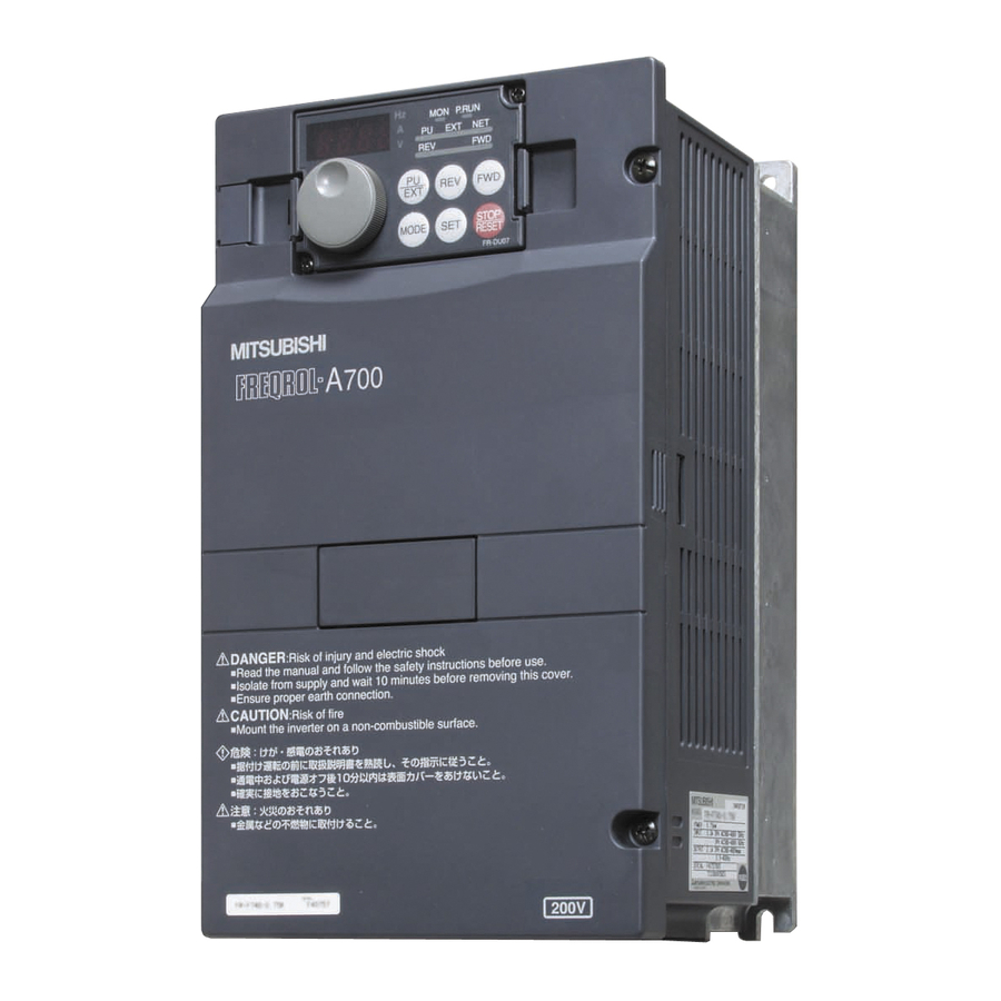
Mitsubishi Electric 700 Series Manuals
Manuals and User Guides for Mitsubishi Electric 700 Series. We have
6
Mitsubishi Electric 700 Series manuals available for free PDF download: Instruction Manual, Programming Manual, Installation Manualline
Mitsubishi Electric 700 Series Instruction Manual (242 pages)
Brand:
Mitsubishi Electric
| Category:
Inverter
| Size: 16.09 MB
Table of Contents
5
Table of Contents
12
1 Outline
13
Product Checking and Parts Identification
14
Inverter and Peripheral Devices
15
Peripheral Devices
16
Removal and Reinstallation of the Cover
16
Front Cover
18
Wiring Cover
19
Installation of the Inverter and Enclosure Design
19
Inverter Installation Environment
21
Cooling System Types for Inverter Enclosure
22
Inverter Placement
24
2 Wiring
25
Terminal Connection Diagram
25
Wiring
26
Main Circuit Terminal Specifications
26
Specification of Main Circuit Terminal
26
Terminal Arrangement of the Main Circuit Terminal, Power Supply and the Motor Wiring
28
Cables and Wiring Length
31
Control Circuit Specifications
31
Control Circuit Terminal
32
Wiring of Control Circuit
34
Connecting the 24V External Power Supply
35
Safety Stop Function
36
Connection of Stand-Alone Option Unit
36
Connection of a Dedicated External Brake Resistor (MRS Type, MYS Type, FR-ABR)
38
Connection of the Brake Unit (FR-BU2)
39
Connection of the DC Reactor (FR-HEL)
40
3 Precautions for Use of the Inverter
41
EMC and Leakage Currents
41
Leakage Currents and Countermeasures
43
EMC Measures
45
Power Supply Harmonics
46
Harmonic Suppression Guideline in Japan
48
Installation of Power Factor Improving Reactor
49
Power-OFF and Magnetic Contactor (MC)
50
Inverter-Driven 400V Class Motor
51
Precautions for Use of the Inverter
53
Failsafe of the System Which Uses the Inverter
57
FL Remote Communication Specification
57
Node Address Setting
58
Wiring
58
Connecting to the Network
58
Precautions for System Configuration
58
Cable Specifications
59
Connecting the FL-Net Dedicated Cable
60
LED Status
60
Device Status LED (DEV), Remote Status LED (RMT)
60
Transmitting (Tx)/Receiving (RX) LED
60
Communication Set Status LED (CHG)
61
Operation Mode Setting
61
Operation Mode Basics
61
FL Remote Communication
62
PU Operation Interlock
62
Operation Availability in each Operation Mode
62
FL Remote Communication
63
Overview of FL Remote Communication
63
FL Remote Data Communication Types
64
Cyclic Transmission
65
Common Memory
68
Output Data (Master to Inverter)
70
Input Data (Inverter to Master)
72
Message Transmission
72
Error Response at Word Block Read/Write
73
Word Block Read/Write
79
Network Parameter Read
80
Log Data Read
80
Log Data Clear
81
Profile Read
82
Message Loopback
84
5 Parameters
85
Operation Panel
85
Names and Functions of the Operation Panel
86
Basic Operation (Factory Setting)
87
Changing the Parameter Setting Value
88
Setting Dial Push
89
Parameter List
95
Control Mode
98
Changing the Control Method (Pr. 80, Pr. 81, Pr. 800)
99
Adjustment of the Output Torque (Current) of the Motor
99
Manual Torque Boost (Pr. 0, Pr. 46)
100
Advanced Magnetic Flux Vector Control (Pr. 71, Pr. 80, Pr. 81, Pr.89, Pr. 800)
103
General-Purpose Magnetic Flux Vector Control (Pr. 71, Pr. 80, Pr. 81, Pr. 800)
105
Slip Compensation (Pr. 245 to Pr. 247)
106
Stall Prevention Operation (Pr. 22, Pr. 23, Pr. 48, Pr. 66, Pr. 156, Pr. 157, Pr. 277)
110
Limiting the Output Frequency
110
Maximum/Minimum Frequency (Pr. 1, Pr. 2, Pr. 18)
111
Avoiding Mechanical Resonance Points (Frequency Jumps) (Pr. 31 to Pr. 36)
112
V/F Pattern
112
Base Frequency, Voltage (Pr. 3, Pr. 19, Pr. 47)
114
Load Pattern Selection (Pr. 14)
116
Frequency Setting by Input Signals
116
Operation by Multi-Speed Operation (Pr. 4 to Pr. 6, Pr. 24 to Pr. 27)
118
Remote Setting Function (Pr. 59)
121
Setting of Acceleration/Deceleration Time and Acceleration/ Deceleration Pattern
121
Setting of the Acceleration and Deceleration Time (Pr. 7, Pr. 8, Pr. 20, Pr. 21, Pr. 44, Pr. 45, Pr. 147)
124
Starting Frequency and Start-Time Hold Function (Pr. 13, Pr. 571)
125
Acceleration/Deceleration Pattern (Pr. 29)
126
Shortest Acceleration/Deceleration (Automatic Acceleration/Deceleration)
126
(Pr. 61 to Pr. 63, Pr. 292, Pr. 293)
128
Selection and Protection of a Motor
128
Motor Overheat Protection (Electronic Thermal O/L Relay) (Pr. 9, Pr. 51)
130
Applied Motor (Pr. 71, Pr. 450)
132
Exhibiting the Best Performance for the Motor (Offline Auto Tuning) (Pr. 71, Pr. 80 to Pr. 84, Pr. 90 to Pr. 94, Pr. 96, Pr. 859)
140
5.10 Motor Brake and Stop Operation
140
DC Injection Brake (Pr. 10 to Pr. 12)
141
Selection of a Regenerative Brake (Pr. 30, Pr. 70)
143
Stop Selection (Pr. 250)
144
Stop-On Contact Control Function (Pr. 6, Pr. 48, Pr. 270, Pr. 275, Pr. 276)
146
5.11 I/O Signal Control
146
Operation of Start Signals (STF, STR Signal)
147
Reset Cancel Signal (READY Signal) and Inverter Running Signal (RUN Signal)
148
Second Function Selection Signal (RT Signal)
148
Inverter Output Shutoff Signal (MRS Signal, Pr. 17)
149
Detection of Output Frequency (SU, FU Signal, Pr. 41 to Pr. 43)
150
Output Current Detection Function (Y12 Signal, Y13 Signal, Pr. 150 to Pr. 153)
151
5.12 Monitor Display and Monitor Output Signal
151
Speed Display and Speed Setting (Pr. 37)
152
Monitor Display Selection of the Operation Panel (Pr. 52, Pr. 170, Pr. 171, Pr. 268, Pr. 563, Pr. 564)
156
Operation Selection at Power Failure and Instantaneous Power Failure
156
Automatic Restart after Instantaneous Power Failure/Flying Start (Pr. 57, Pr. 58, Pr. 96, Pr. 162, Pr. 165, Pr. 298, Pr. 299, Pr. 611)
161
Power-Failure Deceleration Stop Function (Pr. 261)
163
5.14 Operation Setting at Fault Occurrence
163
Retry Function (Pr. 65, Pr. 67 to Pr. 69)
165
Input/Output Phase Loss Protection Selection (Pr. 251, Pr. 872)
165
Earth (Ground) Fault Detection at Start (Pr. 249)
166
Display and Erasure of Communication Error Occurrence Count (Pr. 501)
167
5.15 Energy Saving Operation
167
Optimum Excitation Control (Pr. 60)
168
5.16 Motor Noise, EMI Measures, Mechanical Resonance
168
PWM Carrier Frequency and Soft-PWM Control (Pr. 72, Pr. 240)
169
Speed Smoothing Control (Pr. 653)
170
5.17 Misoperation Prevention and Parameter Setting Restriction
170
Reset Selection/Pu Stop Selection (Pr. 75)
171
Parameter Write Disable Selection (Pr. 77)
172
Reverse Rotation Prevention Selection (Pr. 78)
172
Extended Parameter Display and User Group Function (Pr. 160, Pr. 172 to Pr. 174)
174
Password Function (Pr. 296, Pr. 297)
176
5.18 Special Operation and Frequency Control
176
Jog Operation (Pr. 15, Pr. 16)
178
Droop Control (Pr. 286, Pr. 287)
179
Regeneration Avoidance Function (Pr. 665, Pr. 882, Pr. 883, Pr. 885, Pr. 886)
181
Cooling Fan Operation Selection (Pr. 244)
182
Display of the Life of the Inverter Parts (Pr. 255 to Pr. 259)
185
Maintenance Timer Alarm (Pr. 503, Pr. 504)
186
Free Parameter (Pr. 888, Pr. 889)
187
5.20 Setting from the Operation Panel
187
RUN Key Rotation Direction Selection (Pr. 40)
188
Operation Panel Frequency Setting/Key Lock Operation Selection (Pr. 161)
190
Magnitude of Frequency Change Setting (Pr. 295)
191
5.21 Parameter Clear/ All Parameter Clear
192
5.22 Initial Value Change List
193
5.23 Check and Clear of the Faults History
196
6 Troubleshooting
197
Reset Method of Protective Function
198
List of Fault or Alarm Indications
199
Causes and Corrective Actions
208
Correspondences between Digital and Actual Characters
209
Check First When You Have a Trouble
209
Motor Does Not Start
210
Motor or Machine Is Making Abnormal Acoustic Noise
210
Inverter Generates Abnormal Noise
211
Motor Generates Heat Abnormally
211
Motor Rotates in the Opposite Direction
211
Speed Greatly Differs from the Setting
211
Acceleration/Deceleration Is Not Smooth
212
Speed Varies During Operation
212
Operation Mode Is Not Changed Properly
212
6.5.10 Operation Panel Display Is Not Operating
213
6.5.11 Motor Current Is too Large
213
6.5.12 Speed Does Not Accelerate
213
6.5.13 Unable to Write Parameter Setting
214
6.5.14 Troubleshooting in FL Remote Communication
214
Check First When You Have a Trouble
217
7 Precautions for Maintenance and Inspection
217
Inspection Items
217
Daily Inspection
217
Periodic Inspection
218
Daily and Periodic Inspection
219
Display of the Life of the Inverter Parts
219
Checking the Inverter and Converter Modules
219
Cleaning
220
Replacement of Parts
223
Measurement of Main Circuit Voltages, Currents and Powers
225
Measurement of Powers
225
Measurement of Voltages and Use of PT
226
Measurement of Currents
226
Use of CT and Transducer
226
Measurement of Inverter Input Power Factor
226
Measurement of Converter Output Voltage (Across Terminals P and N)
227
Insulation Resistance Test Using Megger
227
Pressure Test
228
8 Specifications
229
Rating
230
Common Specifications
231
Outline Dimension Drawings
236
Appendix
237
Appendix 1 Specification Change
237
Appendix 1-1 SERIAL Number Check
237
Appendix 1-2 Changed Functions
238
Appendix 2 Index
Advertisement
Mitsubishi Electric 700 Series Programming Manual (183 pages)
700 Series PLC FUNCTION PROGRAMMING MANUAL
Brand:
Mitsubishi Electric
| Category:
Inverter
| Size: 3.64 MB
Table of Contents
2
Table of Contents
6
Plc Function
7
Function Block Diagram
8
PLC Function Specifications
9
System Configuration
10
Wiring of the Inverter and Personal Computer Using GX Developer for RS-485 Communication
11
Prior to Sequence Program Creation
11
Precautions for Sequence Program Creation
11
Usable Main GX Developer Functions
12
Sequence Program Execution Key
13
Sequence Program Write
14
Setting List of Built-In PLC Function Parameter
15
Device Map
15
I/O Device Map
17
Internal Relay (M) Device Map
17
Data Register (D) Device Map
17
Special Relays
19
Special Registers
25
Inverter Status Monitoring, Special Registers for Control
25
Data That Can Be Read at All Times
28
Data That Are Read By Controlling (OFF to ON) the Read Command
30
How to Write Data By Controlling (OFF to ON) the Write Command
36
Inverter Operation Status Control
38
Inverter Parameter Access Error (D9150)
38
Inverter Status (D9151)
39
Inverter Parameter Read/Write Method
39
Reading the Inverter Parameters
41
Writing the Inverter Parameters
43
User Area Read/Write Method
43
User Parameter Read/Write Method
44
Analog I/O Function
44
Analog Input
44
Analog Output
45
Paluse Train Input Function
46
PID Control
48
Inverter Operation Lock Mode Setting
50
CC-Link COMMUNICATION
51
System Configuration
51
System Configuration Example
52
Function Block Diagram
54
CC-Link Parameters
54
CC-Link Extended Setting (Pr. 544)
55
CC-Link I/O Specifications
62
Buffer Memory
62
Remote Output Signals (Master Module to Inverter(Fr-A7Nc))
63
Remote Input Signals Pr.544=100
63
(Inverter(Fr-A7Nc) to Master Module)
64
Remote Registers Pr.544=100
64
(Master Module to Inverter(Fr-A7Nc))
65
Remote Registers Pr.544=100
65
(Inverter(Fr-A7Nc) to Master Module)
66
Sequence Programming
67
Overview
67
Outline of Operation Processings
69
RUN and STOP Operation Processings
69
Program Makeup
70
Programming Languages
70
Relay Symbolic Language (Ladder Mode)
72
Logic Symbolic Language (List Mode)
73
Operation Processing Method of PLC Function
74
I/O Processing Method
74
What Is Refresh System
75
Response Delay in Refresh System
76
Scan Time
77
Numerical Values Usable in Sequence Program
78
BIN (Binary Code)
79
HEX (HEX Decimal)
80
Description of Devices
80
Device List
81
Inputs, Outputs X, Y
84
Internal Relays M
85
Timers T
85
100Ms, 10Ms and 100Ms Retentive Timers
86
Timer Processing Method and Accuracy
88
Counters C
89
Count Processing in Refresh System
90
Maximum Counting Speed of Counter
91
Data Registers D
92
Special Relays, Special Registers
94
Function List
95
How to RUN/STOP the Built-In PLC Function From Outside (Remote RUN/STOP)
97
Watchdog Timer (Operation Clog Up Monitor Timer)
98
Self-Diagnostic Function
99
Error-Time Operation Mode
100
Keyword Registration
101
Setting of Output (Y) Status at Switching From STOP Status to RUN Status
102
Instruction Format
104
Bit Device Processing Method
104
1-Bit Processing
104
Digit Designation Processing
106
Handling of Numerical Value
107
Operation Error
108
Instructions List
108
How to Use the Instruction List
110
Sequence Instruction
112
Basic Instructions
114
Application Instructions
115
Description of the Instructions
116
Sequence Instructions
116
Contact Instructions
116
Operation Start, Series Connection, Parallel Connection
117
Or, Ori
118
Contact Instructions : Ladder Block Series Connection, Parallel Connection
118
Anb, Orb
122
Connection Instructions : Ladder Block Series Connection, Parallel Connection
125
Connection Instructions : Operation Result, Push, Read, Pop
128
Output Instructions : Bit Device, Timer, Counter
131
Output Instructions : Device Set, Reset
132
Program Examples
134
Output Instructions : Leading Edge, Trailing Edge Differential Outputs
134
Plf
136
Shift Instructions : Bit Device Shift
138
Master Control Instructions : Master Control Set, Reset
142
10End Instruction : Sequence Program End
143
11Other Instructions : No Operation
145
Basic Instructions
145
Comparison Operation Instructions
147
Comparison Operation Instructions : 16-Bit Data Comparison
149
Arithmetic Operation Instructions
150
Arithmetic Operation Instructions : BIN 16-Bit Addition, Subtraction
154
Arithmetic Operation Instructions : BIN 16-Bit Multiplication, Division
157
Operation Errors
158
Data Transfer Instructions
158
Data Transfer Instructions : 16-Bit Data Transfer
160
Application Instructions
160
Logical Operation Instructions
161
Logical Operation Instructions : 16-Bit Logical Product
164
Logical Operation Instructions : 16-Bit Logical Add
167
Logical Operation Instructions : 16-Bit Exclusive Logical Add
170
Logical Operation Instructions : 16-Bit NOT Exclusive Logical Add
173
Logical Operation Instructions : BIN 16-Bit 2'S Complement
176
Error Code List
177
How to Read the Error Code
180
Appendix
181
Appendix1Instruction Processing Time
Mitsubishi Electric 700 Series Instruction Manual (45 pages)
Plug-in option
Brand:
Mitsubishi Electric
| Category:
Inverter
| Size: 4.2 MB
Table of Contents
4
Table of Contents
6
1 Pre-Operation Instructions
6
Unpacking and Product Confirmation
6
Product Confirmation (FR-A700/F700 Series)
7
Product Confirmation (FR-E700 Series (E Kit))
8
Parts
9
Specifications
10
2 Installation and Wiring (Fr-A700/F700 Series)
10
Pre-Installation Instructions
11
Installation Procedure
13
Wiring
13
Wiring of FR-A7AX
15
Wiring at Inverter Side
17
3 INSTALLATION and WIRING (FR-E700 SERIES (E Kit))
17
Pre-Installation Instructions
17
Installation Procedure
22
Wiring
22
Wiring of FR-A7AX
24
Wiring of Inverter
25
4 Connection Diagram and Terminal
25
Connection Diagram
27
Internal Block Diagram
28
Terminals
29
Code Input Example
30
5 PARAMETERS Parameter List
32
Parameter Setting
32
Selection of Input Method (Pr. 304) (FR-A700/F700 SERIES)
33
Selection of Input Method (Pr. 304) (FR-E700 Series)
34
Read Timing Operation Selection (Pr. 305)
36
Bias and Gain Adjustment (Pr. 300, Pr. 301, Pr. 302, Pr. 303)
39
Digital Input Unit Selection (Pr. 329)
40
16-Bit Digital Torque Command (FR-A700 Series Only)
44
Instructions
Advertisement
Mitsubishi Electric 700 Series Installation Manualline (43 pages)
Brand:
Mitsubishi Electric
| Category:
Inverter
| Size: 1.5 MB
Table of Contents
1
Table of Contents
6
Installation of the Inverter and Instructions
8
Specifications
11
Wiring
18
Precautions for the Use of the Inverter
20
Failsafe of the System Which Uses the Inverter
21
Parameter
30
A770 Dedicated Specifications
39
Troubleshooting
41
Aappendix
Mitsubishi Electric 700 Series Installation Manualline (43 pages)
Brand:
Mitsubishi Electric
| Category:
Inverter
| Size: 3.98 MB
Table of Contents
1
Table of Contents
4
Product Checking and Parts Identification
6
Outline Dimension Drawings
8
Wiring
18
Precautions for Use of the Inverter
20
Failsafe of the System Which Uses the Inverter
21
Parameter List
25
Troubleshooting
Mitsubishi Electric 700 Series Installation Manualline (25 pages)
Brand:
Mitsubishi Electric
| Category:
Inverter
| Size: 1.4 MB
Table of Contents
3
Fire Prevention
4
Emergency Stop
4
Disposing of the Inverter
4
General Instructions
5
Inverter Type
5
Installation of the Inverter
8
Main Circuit
8
Control Circuit
9
Terminal Layout and Wiring
14
Control Circuit Terminals
14
Terminal Layout
17
List of Alarm Display
Share and save
Advertisement
Related Products
Mitsubishi Electric FR-A 740-00038-EC
Mitsubishi Electric FR-A 740-00250-EC
Mitsubishi Electric FR-A 740-00620-EC
Mitsubishi Electric FR-A 740-00930-EC
Mitsubishi Electric FR-A 740-01800-EC
Mitsubishi Electric FR-A 740-02600-EC
Mitsubishi Electric FR-A 740-09620-EC
Mitsubishi Electric FR-A 740-08660-EC
Mitsubishi Electric FR-F 746-00170-EC
Mitsubishi Electric FR-F 746-00620-EC
Mitsubishi Electric Categories
Air Conditioner
Controller
Projector
Inverter
Monitor
More Mitsubishi Electric Manuals
Login
Sign In
OR
Sign in with Facebook
Sign in with Google
Upload manual
Upload from disk
Upload from URL