Table of Contents
Advertisement
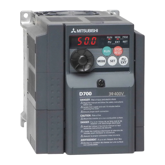
INVERTER
FR-D700
INSTALLATION GUIDELINE
FR-D720-008 to 318-NA
FR-D740-012 to 160-NA
FR-D720S-008 to 100-NA
FR-D710W-008 to 042-NA
Thank you for choosing this Mitsubishi Inverter.
Please read through this Installation Guideline and the CD-ROM enclosed to operate this inverter
correctly.
Do not use this product until you have a full knowledge of the equipment, safety information and
instructions.
Please forward this Installation Guideline and the CD-ROM to the end user.
PRODUCT CHECKING AND PARTS IDENTIFICATION ..........1
1
OUTLINE DIMENSION DRAWINGS ........................................3
2
WIRING ..................................................................................4
3
PRECAUTIONS FOR USE OF THE INVERTER .....................12
4
5
PARAMETER LIST ...............................................................15
6
TROUBLESHOOTING...........................................................19
7
Instruction Manual [IB(NA)-0600368ENG]
Safety stop function instruction manual [BCN-A211508-000]
These manuals are required if you are going to utilize functions and
performance.
CONTENTS
700
Advertisement
Table of Contents

Related Manuals for Mitsubishi Electric FR-D720-008


Summary of Contents for Mitsubishi Electric FR-D720-008
-
Page 1: Table Of Contents
INVERTER FR-D700 INSTALLATION GUIDELINE FR-D720-008 to 318-NA FR-D740-012 to 160-NA FR-D720S-008 to 100-NA FR-D710W-008 to 042-NA Thank you for choosing this Mitsubishi Inverter. Please read through this Installation Guideline and the CD-ROM enclosed to operate this inverter correctly. Do not use this product until you have a full knowledge of the equipment, safety information and instructions. - Page 2 This Installation Guideline provides handling information and precautions for use of the equipment. Please forward this Installation Guideline to the end user. 2. Fire Prevention This section is specifically about safety matters CAUTION Do not attempt to install, operate, maintain or inspect the Inverter must be installed on a nonflammable wall without inverter until you have read through the Installation holes (so that nobody touches the inverter heatsink on the...
- Page 3 (2) Wiring CAUTION CAUTION The electronic thermal relay function does not guarantee Do not install a power factor correction capacitor or surge protection motor from overheating. suppressor/capacitor type filter on the inverter output recommended to install both an external thermal and PTC side.
-
Page 4: Product Checking And Parts Identification
Serial number Single-phase 100V class Installation of the inverter Enclosure surface mounting Remove the front cover and wiring cover to mount the inverter to the surface. FR-D720-008 to 042 FR-D720-070 or higher FR-D720S-008 to 042 FR-D740-012 or higher FR-D710W-008 to 025... - Page 5 PRODUCT CHECKING AND PARTS IDENTIFICATION General Precaution The bus capacitor discharge time is 10 minutes. Before starting wiring or inspection, switch power OFF, wait for more than 10 minutes, and check for residual voltage between terminal P/+ and N/- with a meter etc., to avoid a hazard of electrical shock. Environment Before installation, check that the environment meets the following specifications.
-
Page 6: Outline Dimension Drawings
2 OUTLINE DIMENSION DRAWINGS FR-D720-008 to 042 FR-D720-070 to 318 FR-D720S-008 to 042 FR-D740-012 to 160 FR-D710W-008 to 025 FR-D720S-070, 100 FR-D710W-042 2-φC hole 1-φC hole (Unit:mm(inches)) • Three-phase 200V class Inverter Model FR-D720-008 80.5(3.17) FR-D720-014 68(2.68) 56(2.20) 112.5(4.43) FR-D720-025 FR-D720-042 128(5.04) -
Page 7: Wiring
AC power S/L2 overheat and burnout of the brake resistor. (Ground) supply (The brake resistor can not be connected Jumper PR N/- to the FR-D720-008 and 014, FR-D720S- 008 and 014, FR-D710W-008 and 014.) MCCB Motor R/L1 Three-phase S/L2 AC power... -
Page 8: Main Circuit Terminal Specifications
WIRING Main circuit terminal specifications 3.2.1 Terminal arrangement of the main circuit terminal, power supply and the motor wiring Three-phase 200V class FR-D720-008 to 042 FR-D720-070 to 165 Jumper Screw size (M3.5) Jumper N/- P/+ Screw size (M4) R/L1 S/L2 T/L3... - Page 9 WIRING Single-phase 100V class FR-D710W-008 to 025 FR-D710W-042 Screw size (M3.5) N/- P/+ Screw size (M4) R/L1 S/L2 R/L1 S/L2 Screw size Screw size (M3.5) (M4) Power supply Motor Power supply Motor NOTE Make sure the power cables are connected to the R/L1, S/L2, T/L3. (Phase need not be matched.) Never connect the power cable to the U, V, W of the inverter.
-
Page 10: Cables And Wiring Length
U, V, W (ground) S/L2 U, V, W S/L2 U, V, W (ground) T/L3 T/L3 cable T/L3 T/L3 cable FR-D720-008 to 042 M3.5 2-3.5 2-3.5 FR-D720-070 and 100 FR-D720-165 5.5-4 5.5-4 FR-D720-238 5.5-5 5.5-5 FR-D720-318 14-5 Three-phase 400V class (when input power supply is 440V) - Page 11 WIRING NOTE Tighten the terminal screw to the specified torque. A screw that has been tighten too loosely can cause a short circuit or malfunction. A screw that has been tighten too tightly can cause a short circuit or malfunction due to the unit breakage. Use crimping terminals with insulation sleeve to wire the power supply and motor.
- Page 12 WIRING Total wiring length The overall wiring length for connection of a single motor or multiple motors should be within the value in the table below. 100V, 200V class Pr. 72 PWM frequency selection setting (carrier frequency) or Higher 200m 200m 300m 500m...
-
Page 13: Control Circuit Specifications
WIRING Control circuit specifications (1) Control circuit terminal layout Recommended wire size: 0.3mm to 0.75mm RUN SE S1 S2 SC STF STR (2) Wiring method Wiring Use a blade terminal and a wire with a sheath stripped off for the control circuit wiring. For a single wire, strip off the sheath of the wire and apply directly. - Page 14 WIRING 3) Insert the wire into a socket. When using a single wire or stranded wire without a blade terminal, push an open/ close button all the way down with a flathead screw driver, and insert the wire. Open/close button Flathead screwdriver Note When using a stranded wire without a blade terminal, twist enough to avoid short circuit with a nearby terminals or...
-
Page 15: Precautions For Use Of The Inverter
(11) Across P/+ and PR terminals, connect only the brake resistor. The brake resistor cannot be connected to the FR-D720-008 and 014, FR-D720S-008 and 014, FR-D710W-008 and 014. Do not connect a mechanical brake. Leave terminals P/+ and PR open. Also, never short between P/+ and PR. - Page 16 PRECAUTIONS FOR USE OF THE INVERTER (12) Do not apply a voltage higher than the permissible voltage to the inverter I/O signal circuits. Application of a voltage higher than the permissible voltage to the inverter I/O signal circuits or opposite polarity may damage the I/O devices.
-
Page 17: Failsafe Of The System Which Uses The Inverter
FAILSAFE OF THE SYSTEM WHICH USES THE INVERTER FAILSAFE OF THE SYSTEM WHICH USES THE INVERTER When a fault occurs, the inverter trips to output a fault signal. However, a fault output signal may not be output at an inverter fault occurrence when the detection circuit or output circuit fails, etc. -
Page 18: Parameter List
PARAMETER LIST 6 PARAMETER LIST For simple variable-speed operation of the inverter, the initial setting of the parameters may be used. Set the necessary parameters to meet the load and operational specifications. Parameter setting, change and check can be made from the operation panel. - Page 19 PARAMETER LIST Initial Initial Name Setting Range Name Setting Range Value Value 0, 0.1 to 5s, 0.1 to 1000%, Restart coasting time 9999 PID proportional band 100% 9999 9999 Restart cushion time 0 to 60s 0.1 to 3600s, PID integral time Remote function selection 0, 1, 2, 3 9999...
- Page 20 PARAMETER LIST Initial Initial Name Setting Range Name Setting Range Value Value Monitor decimal digits 0, 1, 3, 4, 7, 8, 0, 1, 9999 9999 selection 11 to 16, 25, 26, RUN terminal function Parameter for manufacturer setting. Do not set. 46, 47, 64, 70, selection Magnitude of frequency...
- Page 21 10s: FR-D720-238 and 318, FR-D740-120 and 160 value ∗3 Differ according to capacities. Regeneration avoidance 6%: FR-D720-008 and 014, FR-D720S-008 and 014, FR-D710W-008 and 0 to 200% 100% voltage gain 4%: FR-D720-025 to 318, FR-D740-012 to 160, FR-D720S-025 to 100,...
-
Page 22: Troubleshooting
TROUBLESHOOTING 7 TROUBLESHOOTING When a fault occurs in the inverter, the inverter trips and the PU display automatically changes to one of the following fault or alarm indications. If the fault does not correspond to any of the following faults or if you have any other problem, please contact your sales representative. -
Page 23: List Of Fault Or Alarm Indications
TROUBLESHOOTING List of fault or alarm indications Operation Panel Operation Panel Name Name Indication Indication E.ILF ∗ Input phase loss E--- Faults history E.OLT Stall prevention stop HOLD Operation panel lock E. BE Brake transistor alarm detection Er1 to 4 Parameter write error Output side earth (ground) fault E.GF... - Page 24 CE marking. The authorized representative in the EU The authorized representative in the EU is shown below. Name: Mitsubishi Electric Europe B.V. Address: Gothaer Strasse 8, 40880 Ratingen, Germany Note We declare that this inverter, when equipped with the dedicated EMC filter, conforms with the EMC Directive in industrial environments and affix the CE marking on the inverter.
- Page 25 (2) Low Voltage Directive We have self-confirmed our inverters as products compliant to the Low Voltage Directive (Conforming standard EN 61800- 5-1) and affix the CE marking on the inverters. Outline of instructions ∗ Do not use an earth leakage circuit breaker as an electric shock protector without connecting the equipment to the earth. Connect the equipment to the earth securely.
- Page 26 ∗ Select a UL and cUL certified fuse with Class T fuse equivalent cut-off speed or faster with the appropriate rating for branch circuit protection, or a UL489 molded case circuit breaker (MCCB) in accordance with the table below. FR-D720- Rated fuse voltage(V) 240V or more Without power factor improving reactor...
-
Page 27: Appendix 2 Instructions For Ul And Cul
Appendix 2 Instructions for UL and cUL (Standard to comply with: UL 508C, CSA C22.2 No. 14) 1. General Precaution The bus capacitor discharge time is 10 minutes. Before starting wiring or inspection, switch power off, wait for more than 10 minutes, and check for residual voltage between terminal P/+ and N/- with a meter etc., to avoid a hazard of electrical shock. - Page 28 REVISIONS *The manual number is given on the bottom left of the back cover. Print Date Revision Manual Number Sep. 2008 IB-0600367ENG-A First edition Oct. 2008 IB-0600367ENG-B Addition FR-D710W-008 to 042-NA Jun. 2009 IB-0600367ENG-C Addition • Setting values "81, 181" of Pr.190 and Pr.192 (Output terminal function selection) •...
- Page 29 • The copyright and other rights of this CD-ROM all belong to Mitsubishi Electric Corporation. • No part of this CD-ROM may be copied or reproduced without the permission of Mitsubishi Electric Corporation. • Specifications of this CD-ROM are subject to change for modification without notice.
- Page 30 HEADQUARTERS EUROPEAN REPRESENTATIVES EUROPEAN REPRESENTATIVES EUROPEAN REPRESENTATIVES MITSUBISHI ELECTRIC EUROPE GEVA AUSTRIA MITSUBISHI ELECTRIC IRELAND Beijer Electronics AB SWEDEN EUROPE B.V. Wiener Straße 89 EUROPE B.V.-Irish Branch Box 426 German Branch A-2500 Baden Westgate Business Park S-20123 Malmö Gothaer Straße 8...
Need help?
Do you have a question about the FR-D720-008 and is the answer not in the manual?
Questions and answers