Mitsubishi Electric FR-D720-0.4K Instruction Manual
Hide thumbs
Also See for FR-D720-0.4K:
- Instruction manual (60 pages) ,
- Instruction manual (313 pages) ,
- Instruction manual (311 pages)
Table of Contents
Advertisement
Quick Links
Advertisement
Table of Contents

Related Manuals for Mitsubishi Electric FR-D720-0.4K


Summary of Contents for Mitsubishi Electric FR-D720-0.4K
- Page 1 INVERTER FR-D700 INSTRUCTION MANUAL (Applied) FR-D720-0.1K to 15K FR-D740-0.4K to 15K FR-D720S-0.1K to 2.2K FR-D710W-0.1K to 0.75K OUTLINE WIRING PRECAUTIONS FOR USE OF THE INVERTER PARAMETERS TROUBLESHOOTING PRECAUTIONS FOR MAINTENANCE AND INSPECTION SPECIFICATIONS...
- Page 2 Thank you for choosing this Mitsubishi Inverter. This Instruction Manual (Applied) provides instructions for advanced use of the FR-D700 series inverters. Incorrect handling might cause an unexpected fault. Before using the inverter, always read this Instruction Manual and the Instruction Manual (Basic) [IB-0600438ENG] packed with the product carefully to use the equipment to its optimum performance.
- Page 3 (2) Wiring (5) Emergency stop CAUTION CAUTION Do not install a power factor correction capacitor or surge A safety backup such as an emergency brake must be suppressor/capacitor type filter on the inverter output side. provided to prevent hazardous condition to the machine These devices on the inverter output side may be and equipment in case of inverter failure.
-
Page 4: Table Of Contents
CONTENTS OUTLINE Product checking and parts identification ......... 2 Inverter and peripheral devices ............3 1.2.1 Peripheral devices .......................... 4 Removal and reinstallation of the cover..........5 1.3.1 Front cover ............................. 5 1.3.2 Wiring cover............................ 7 Installation of the inverter and enclosure design ......8 1.4.1 Inverter installation environment..................... - Page 5 3.1.1 Leakage currents and countermeasures ..................38 3.1.2 EMC measures ..........................40 3.1.3 Power supply harmonics....................... 42 3.1.4 Harmonic suppression guideline in Japan ..................43 Installation of power factor improving reactor........ 45 Power-OFF and magnetic contactor (MC) ........46 Inverter-driven 400V class motor ............. 47 Precautions for use of the inverter ..........
- Page 6 deceleration pattern................. 97 4.7.1 Setting of the acceleration and deceleration time (Pr. 7, Pr. 8, Pr. 20, Pr. 44, Pr. 45) ..................... 97 4.7.2 Starting frequency and start-time hold function (Pr. 13, Pr. 571) ..........99 4.7.3 Acceleration/deceleration pattern (Pr. 29) ................. 100 Selection and protection of a motor ..........
- Page 7 4.14 Energy saving operation ..............148 4.14.1 Optimum excitation control (Pr. 60) ................... 148 4.15 Motor noise, EMI measures, mechanical resonance ....149 4.15.1 PWM carrier frequency and Soft-PWM control (Pr. 72, Pr. 240, Pr. 260)........149 4.15.2 Speed smoothing control (Pr. 653) .................... 150 4.16 Frequency setting by analog input (terminal 2, 4) ......
- Page 8 4.21.5 Free parameter (Pr. 888, Pr. 889) ..................... 235 4.22 Setting the parameter unit and operation panel ......236 4.22.1 RUN key rotation direction selection (Pr. 40) ................236 4.22.2 PU display language selection (Pr.145) ..................236 4.22.3 Operation panel frequency setting/key lock selection (Pr. 161) ..........237 4.22.4 Magnitude of frequency change setting (Pr.
- Page 9 Inspection items ................274 6.1.1 Daily inspection........................... 274 6.1.2 Periodic inspection........................274 6.1.3 Daily and periodic inspection ...................... 275 6.1.4 Display of the life of the inverter parts ..................276 6.1.5 Checking the inverter and converter modules ................277 6.1.6 Cleaning............................
- Page 10 OUTLINE This chapter explains the "OUTLINE" for use of this product. Always read the instructions before using the equipment. Product checking and parts identification ......... 2 Inverter and peripheral devices........... 3 Removal and reinstallation of the cover ........5 Installation of the inverter and enclosure design ...... 8 <Abbreviation>...
-
Page 11: Product Checking And Parts Identification
Product checking and parts identification Product checking and parts identification Unpack the inverter and check the capacity plate on the front cover and the rating plate on the inverter side face to ensure that the product agrees with your order and the inverter is intact. Inverter model FR - D740... -
Page 12: Inverter And Peripheral Devices
Inverter and peripheral devices Inverter and peripheral devices AC power supply Use within the permissible power supply specifications of the inverter. To ensure safety, use a moulded case circuit breaker, RS-232C - RS-485 converter is Enclosure surface operation earth leakage circuit breaker or magnetic required when connecting to PC panel (FR-PA07) contactor to switch power ON/OFF. -
Page 13: Peripheral Devices
Reactor connection FR-HAL FR-HEL without with without with 0.4K ∗5 0.4K ∗5 FR-D720-0.1K S-N10 S-N10 0.4K ∗5 0.4K ∗5 FR-D720-0.2K S-N10 S-N10 FR-D720-0.4K S-N10 S-N10 0.4K 0.4K FR-D720-0.75K 0.75 S-N10 S-N10 0.75K 0.75K FR-D720-1.5K S-N10 S-N10 1.5K 1.5K FR-D720-2.2K S-N10 S-N10 2.2K... -
Page 14: Removal And Reinstallation Of The Cover
Removal and reinstallation of the cover Removal and reinstallation of the cover 1.3.1 Front cover 3.7K or lower Removal (Example of FR-D740-1.5K) 1) Loosen the mounting screws of the front cover. (The screws cannot be removed.) 2) Remove the front cover by pulling it like the direction of arrow. Mounting screw Reinstallation (Example of FR-D740-1.5K) 1) Place the front cover in front of the inverter, and install it straight. - Page 15 Removal and reinstallation of the cover 5.5K or higher Removal (Example of FR-D740-7.5K) 1) Loosen the mounting screws of the front cover. (The screws cannot be removed.) 2) Remove the front cover by pulling it like the direction of arrow with holding the installation hook on the front cover. Installation hook Mounting screw...
-
Page 16: Wiring Cover
Removal and reinstallation of the cover 1.3.2 Wiring cover Removal and reinstallation 3.7K or lower Hold the side of the wiring cover, and pull it downward for Also pull the wiring cover downward by holding a removal. frontal part of the wiring cover. To reinstall, fit the cover to the inverter along the guides. -
Page 17: Installation Of The Inverter And Enclosure Design
Installation of the inverter and enclosure design Installation of the inverter and enclosure design When an inverter enclosure is to be designed and manufactured, heat generated by contained equipment, etc., the environment of an operating place, and others must be fully considered to determine the enclosure structure, size and equipment layout. - Page 18 Installation of the inverter and enclosure design Dust, dirt, oil mist Dust and dirt will cause such faults as poor contact of contact points, reduced insulation or reduced cooling effect due to moisture absorption of accumulated dust and dirt, and in-enclosure temperature rise due to clogged filter. In the atmosphere where conductive powder floats, dust and dirt will cause such faults as malfunction, deteriorated insulation and short circuit in a short time.
-
Page 19: Cooling System Types For Inverter Enclosure
Installation of the inverter and enclosure design 1.4.2 Cooling system types for inverter enclosure From the enclosure that contains the inverter, the heat of the inverter and other equipment (transformers, lamps, resistors, etc.) and the incoming heat such as direct sunlight must be dissipated to keep the in-enclosure temperature lower than the permissible temperatures of the in-enclosure equipment including the inverter. -
Page 20: Inverter Placement
Installation of the inverter and enclosure design 1.4.3 Inverter placement Installation of the inverter Enclosure surface mounting Remove the front cover and wiring cover to mount the inverter to the surface. (Remove the covers in the directions of the arrows.) FR-D720-0.1K to 0.75K FR-D720-1.5K to 3.7K FR-D720-5.5K to 15K... - Page 21 Installation of the inverter and enclosure design Inverter mounting orientation Mount the inverter on a wall as specified. Do not mount it horizontally or any other way. Above inverter Heat is blown up from inside the inverter by the small fan built in the unit. Any equipment placed above the inverter should be heat resistant.
-
Page 22: Wiring
WIRING This chapter describes the basic "WIRING" for use of this product. Always read the instructions before using the equipment. Wiring..................... 14 Main circuit terminal specifications ..........15 Control circuit specifications ............20 Connection of stand-alone option unit ........31... -
Page 23: Terminal Connection Diagram
Wiring Wiring 2.1.1 Terminal connection diagram 1. DC reactor (FR-HEL) When connecting a DC reactor, remove the Sink logic jumper across P1 and P/+ *6 Terminal P1 is not available for single- Main circuit terminal Single-phase 100V power input model is not phase 100V power input model. -
Page 24: Main Circuit Terminal Specifications
Main circuit terminal specifications Main circuit terminal specifications 2.2.1 Specification of main circuit terminal Terminal Terminal Name Description Symbol R/L1, Connect to the commercial power supply. S/L2, AC power input Keep these terminals open when using the high power factor converter (FR-HC) or T/L3 ∗1 power regeneration common converter (FR-CV). - Page 25 Main circuit terminal specifications Three-phase 400V class FR-D740-0.4K to 3.7K FR-D740-5.5K, 7.5K Jumper Jumper N/- P/+ R/L1 S/L2 T/L3 R/L1 S/L2 T/L3 P/+ PR Power supply Motor Power supply Motor FR-D740-11K, 15K P/+ PR R/L1 S/L2 T/L3 Jumper Power supply Motor Single-phase 200V class FR-D720S-0.1K to 0.75K...
-
Page 26: Cables And Wiring Length
Main circuit terminal specifications 2.2.3 Cables and wiring length Applied wire size Select the recommended cable size to ensure that a voltage drop will be 2% or less. If the wiring distance is long between the inverter and motor, a main circuit cable voltage drop will cause the motor torque to decrease especially at the output of a low frequency. - Page 27 Main circuit terminal specifications Earthing (Grounding) precautions Always earth (ground) the motor and inverter. 1) Purpose of earthing (grounding) Generally, an electrical apparatus has an earth (ground) terminal, which must be connected to the ground before use. An electrical circuit is usually insulated by an insulating material and encased. However, it is impossible to manufacture an insulating material that can shut off a leakage current completely, and actually, a slight current flow into the case.
- Page 28 Main circuit terminal specifications Total wiring length The overall wiring length for connection of a single motor or multiple motors should be within the value in the table below. 100V, 200V class Pr. 72 PWM frequency selection Setting 1.5K or 0.1K 0.2K 0.4K...
-
Page 29: Control Circuit Specifications
Control circuit specifications Control circuit specifications 2.3.1 Control circuit terminal indicates that terminal functions can be selected using Pr. 178 to Pr. 182, Pr. 190, Pr. 192, Pr. 197 (I/O terminal function selection). (Refer to page 114). Input signal Terminal Refer to Type Terminal Name... - Page 30 Control circuit specifications NOTE Set Pr. 267 and a voltage/current input switch correctly, then input analog signals in accordance with the settings. Applying a voltage with voltage/current input switch in "I" position (current input is selected) or a current with switch in "V"...
-
Page 31: Changing The Control Logic
Control circuit specifications 2.3.2 Changing the control logic The input signals are set to sink logic (SINK) when shipped from the factory. To change the control logic, the jumper connector above the control terminal must be moved to the other position. Change the jumper connector in the sink logic (SINK) position to source logic (SOURCE) position using tweezers, a pair of long-nose pliers etc. - Page 32 Control circuit specifications (1) Sink logic type and source logic type In sink logic, a signal switches ON when a current flows from the corresponding signal input terminal. Terminal SD is common to the contact input signals. Terminal SE is common to the open collector output signals. In source logic, a signal switches ON when a current flows into the corresponding signal input terminal.
-
Page 33: Wiring Of Control Circuit
Control circuit specifications 2.3.3 Wiring of control circuit Standard control circuit terminal layout Recommend wire size: 0.3mm to 0.75mm RUN SE S1 S2 SC STF STR Wiring method Wiring Use a blade terminal and a wire with a sheath stripped off for the control circuit wiring. For a single wire, strip off the sheath of the wire and apply directly. - Page 34 Control circuit specifications 3) Insert the wire into a socket. When using a single wire or a stranded wire without a blade terminal, push an open/close button all the way down with a flathead screw driver, and insert the wire. Open/close button Flathead screwdriver NOTE...
- Page 35 Control circuit specifications Signal inputs by contactless switches The contacted input terminals of the inverter (STF, STR, RH, RM, RL) can be controlled using a transistor +24V instead of a contacted switch as shown on the right. STF, etc. Inverter External signal input using transistor Wiring instructions 1) It is recommended to use the cables of 0.3mm...
-
Page 36: Safety Stop Function
Control circuit specifications 2.3.4 Safety stop function Description of the function The terminals related to the safety stop function are shown below. Refer to page 20 for the rated specification of each terminal. Terminal Description Symbol For input of safety stop channel 1. Between S1 and SC / S2 and SC ∗1 Open: In safety stop mode. - Page 37 Control circuit specifications Safety stop function operation Input signal Internal Output signal Input power safety Inverter operation state S1-SC S2-SC SAFE SAFE2 ∗2 ∗2 circuit ∗1 ----- ---- - ----- Output shutoff (Safe state) No failure Drive enabled Short Short Failure Output shutoff (Safe state) No failure...
-
Page 38: Connection To The Pu Connector
Control circuit specifications 2.3.5 Connection to the PU connector Using the PU connector, you can perform communication operation from the parameter unit (FR-PA07), enclosure surface operation panel (FR-PA07), or a personal computer, etc. Parameter setting and monitoring can be performed by FR Configurator (FR-SW3-SETUP-W ). Remove the inverter front cover when connecting. - Page 39 Control circuit specifications RS-485 communication When the PU connector is connected with a personal, FA or other computer by a communication cable, a user program can run and monitor the inverter or read and write to parameters. The protocol can be selected from Mitsubishi inverter and Modbus-RTU. PU connector pin-outs Name Description...
-
Page 40: Connection Of Stand-Alone Option Unit
(used at 100% torque/6%ED) Refer to page 7.5K or lower FR-ABR 11K or higher FR-D720-1.5K to 3.7K FR-D720-0.4K, 0.75K FR-D740-0.4K to 3.7K FR-D720S-0.4K, 0.75K FR-D720S-1.5K, 2.2K FR-D710W-0.4K FR-D710W-0.75K Connect the brake resistor across terminals P/+ and PR. Connect the brake resistor across terminals P/+ and PR. - Page 41 Connection of stand-alone option unit It is recommended to configure a sequence, which shuts off power in the input side of the inverter by the external thermal relay as shown below, to prevent overheat and burnout of the brake resistor (MRS type, MYS type) and high duty brake resistor (FR-ABR) in case the regenerative brake transistor is damaged.
-
Page 42: Connection Of The Brake Unit (Fr-Bu2)
Connection of stand-alone option unit 2.4.2 Connection of the brake unit (FR-BU2) Connect the brake unit (FR-BU2(-H)) as shown below to improve the braking capability at deceleration. If the transistors in the brake unit should become faulty, the resistor can be unusually hot. To prevent unusual overheat and fire, install a magnetic contactor on the inverter's input side to configure a circuit so that a current is shut off in case of fault. -
Page 43: Connection Of The High Power Factor Converter (Fr-Hc)
Connection of stand-alone option unit Connection example with the FR-BR(-H) type resistor ∗2 FR-BR MCCB Motor ∗4 R/L1 Three-phase AC S/L2 power supply T/L3 ∗3 FR-BU2 Inverter ∗1 ∗1 ∗5 ∗3 5m or less ∗1 Connect the inverter terminals (P/+ and N/-) and brake unit (FR-BU2) terminals so that their terminal names match with each other. (Incorrect connection will damage the inverter and brake unit.) ∗2 When the power supply is 400V class, install a step-down transformer. -
Page 44: Connection Of The Power Regeneration Common Converter (Fr-Cv)
Connection of stand-alone option unit 2.4.4 Connection of the power regeneration common converter (FR-CV) When connecting the power regeneration common converter (FR-CV), connect the inverter terminals (P/+ and N/-) and power regeneration common converter (FR-CV) terminals as shown below so that their symbols match with each other. After making sure that the wiring is correct, set "2"... - Page 45 MEMO...
-
Page 46: Precautions For Use Of The Inverter
PRECAUTIONS FOR USE OF THE INVERTER This chapter explains the "PRECAUTIONS FOR USE OF THE INVERTER" for use of this product. Always read the instructions before using the equipment. EMC and leakage currents ............38 Installation of power factor improving reactor ......45 Power-OFF and magnetic contactor (MC) ......... -
Page 47: Emc And Leakage Currents
EMC and leakage currents EMC and leakage currents 3.1.1 Leakage currents and countermeasures Capacitances exist between the inverter I/O cables, other cables and earth and in the motor, through which a leakage current flows. Since its value depends on the static capacitances, carrier frequency, etc., low acoustic noise operation at the increased carrier frequency of the inverter will increase the leakage current. - Page 48 EMC and leakage currents Selection of rated sensitivity current of earth (ground) leakage current breaker When using the earth leakage current breaker with the inverter circuit, select its rated sensitivity current as follows, independently of the PWM carrier frequency. Breaker designed for harmonic and Ig1, Ig2: Leakage currents in wire path during commercial surge suppression...
-
Page 49: Emc Measures
EMC and leakage currents 3.1.2 EMC measures Some electromagnetic noises enter the inverter to malfunction it and others are radiated by the inverter to malfunction peripheral devices. Though the inverter is designed to have high immunity performance, it handles low-level signals, so it requires the following basic techniques. -
Page 50: Precautions For Use Of The Inverter
EMC and leakage currents Propagation Path Measures When devices that handle low-level signals and are liable to malfunction due to electromagnetic noises, e.g. instruments, receivers and sensors, are contained in the enclosure that contains the inverter or when their signal cables are run near the inverter, the devices may malfunction due to air-propagated electromagnetic noises. -
Page 51: Power Supply Harmonics
EMC and leakage currents 3.1.3 Power supply harmonics The inverter may generate power supply harmonics from its converter circuit to affect the power generator, power capacitor etc. Power supply harmonics are different from noise and leakage currents in source, frequency band and transmission path. Take the following countermeasure suppression techniques. -
Page 52: Harmonic Suppression Guideline In Japan
EMC and leakage currents 3.1.4 Harmonic suppression guideline in Japan Harmonic currents flow from the inverter to a power receiving point via a power transformer. The Harmonic Suppression Guidelines was established to protect other consumers from these outgoing harmonic currents. The three-phase 200V input specifications 3.7kW or less (single-phase 200V power input model 2.2kW or less, single-phase 100V power input model 0.75kW) are previously covered by "Harmonic Suppression Guidelines for Household Appliances and General-purpose Products"... - Page 53 EMC and leakage currents Table 4 Harmonic Contents (Values at the fundamental current of 100%) Reactor 11th 13th 17th 19th 23rd 25th Not used Three-phase bridge Used (AC side) 14.5 (Capacitor smoothing) Used (DC side) Used (AC, DC sides) ⎯ ⎯...
-
Page 54: Installation Of Power Factor Improving Reactor
Installation of power factor improving reactor Installation of power factor improving reactor When the inverter is connected near a large-capacity power transformer (500kVA or more) or when a power capacitor is to be switched over, an excessive peak current may flow in the power input circuit, damaging the converter circuit. To prevent this, always install an optional reactor (FR-HAL, FR-HEL). -
Page 55: Power-Off And Magnetic Contactor (Mc)
Power-OFF and magnetic contactor (MC) Power-OFF and magnetic contactor (MC) Inverter input side magnetic contactor (MC) On the inverter input side, it is recommended to provide an MC for the following purposes. (Refer to page 4 for selection.) 1) To release the inverter from the power supply when the fault occurs or when the drive is not functioning (e.g. emergency stop operation). -
Page 56: Inverter-Driven 400V Class Motor
Inverter-driven 400V class motor Inverter-driven 400V class motor In the PWM type inverter, a surge voltage attributable to wiring constants is generated at the motor terminals. Especially for a 400V class motor, the surge voltage may deteriorate the insulation. When the 400V class motor is driven by the inverter, consider the following measures: Measures It is recommended to take either of the following measures:... -
Page 57: Precautions For Use Of The Inverter
Precautions for use of the inverter Precautions for use of the inverter The FR-D700 series is a highly reliable product, but using incorrect peripheral circuits or incorrect operation/handling methods may shorten the product life or damage the product. Before starting operation, always recheck the following items. (1) Use crimping terminals with insulation sleeve to wire the power supply and motor. - Page 58 Precautions for use of the inverter (12) Do not apply a voltage higher than the permissible voltage to the inverter I/O signal circuits. Application of a voltage higher than the permissible voltage to the inverter I/O signal circuits or opposite polarity may damage the I/O devices.
-
Page 59: Failsafe Of The System Which Uses The Inverter
Failsafe of the system which uses the inverter Failsafe of the system which uses the inverter When a fault occurs, the inverter trips to output a fault signal. However, a fault output signal may not be output at an inverter fault occurrence when the detection circuit or output circuit fails, etc. - Page 60 Failsafe of the system which uses the inverter 4)Checking the motor operating status by the start signal input to the inverter and inverter output current detection signal. The output current detection signal (Y12 signal) is output when the inverter operates and currents flows in the motor. Check if Y12 signal is output when inputting the start signal to the inverter (forward signal is STF signal and reverse signal is STR signal).
- Page 61 MEMO...
-
Page 62: Parameters
PARAMETERS This chapter explains the "PARAMETERS" for use of this product. Always read the instructions before using the equipment. The following marks are used to indicate the controls as below..V/F control ..General-purpose magnetic flux vector control GP MFVC GP MFVC GP MFVC (Parameters without any mark are valid for both controls.) -
Page 63: Operation Panel
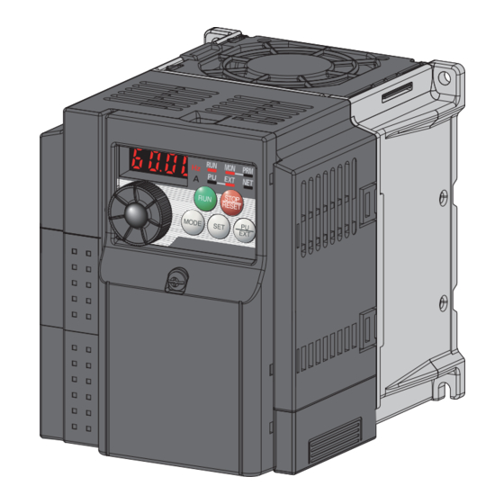
Operation panel Operation panel 4.1.1 Names and functions of the operation panel The operation panel cannot be removed from the inverter. Operation mode indicator Operating status indicator ∗ Lit or flicker during inverter operation. PU: Lit to indicate PU operation mode. * Lit: When the forward rotation operation EXT: Lit to indicate External operation mode. -
Page 64: Basic Operation (Factory Setting)
Operation panel 4.1.2 Basic operation (factory setting) Operation mode switchover At power-ON (External operation mode) PU Jog operation mode (Example) PU operation mode Value change and frequency flicker. (output frequency monitor) Frequency setting has been written and completed!! STOP Output current monitor Output voltage monitor Display the Parameter setting mode... -
Page 65: Easy Operation Mode Setting (Easy Setting Mode)
Operation panel 4.1.3 Easy operation mode setting (easy setting mode) Setting of Pr. 79 Operation mode selection according to combination of the start command and speed command can be easily made. Changing Start command: external (STF/STR), frequency command: operate with example Operation Display... -
Page 66: Changing The Parameter Setting Value
Operation panel 4.1.4 Changing the parameter setting value Changing Change the Pr. 1 Maximum frequency setting. example Operation Display Screen at power-ON The monitor display appears. PU indicator is lit. Press to choose the PU operation mode. PRM indicator is lit. Press to choose the parameter setting mode. -
Page 67: Parameter List
Parameter list Parameter list Parameter list 4.2.1 Parameter list For simple variable-speed operation of the inverter, the initial setting of the parameters may be used. Set the necessary parameters to meet the load and operational specifications. Parameter setting, change and check can be made from the operation panel. - Page 68 Parameter list Parameter list Control Mode-based Minimum Refer Instruction Code Parameter Func- Initial Customer Correspondence Table Parameter Name Setting Range Setting Parameter Remarks tion Value Setting Increments Page Read Write Extended Copy Clear All clear GP MFVC GP MFVC GP MFVC 111, —...
- Page 69 Parameter list Parameter list Control Mode-based Minimum Refer Instruction Code Parameter Func- Initial Customer Correspondence Table Parameter Name Setting Range Setting Parameter Remarks tion Value Setting Increments Page Read Write Extended Copy Clear All clear GP MFVC GP MFVC GP MFVC ×...
- Page 70 Parameter list Parameter list Control Mode-based Minimum Refer Instruction Code Parameter Func- Initial Customer Correspondence Table Parameter Name Setting Range Setting Parameter Remarks tion Value Setting Increments Page Read Write Extended Copy Clear All clear GP MFVC GP MFVC GP MFVC Output current detection signal 0 to 10s, 9999 0.1s...
- Page 71 Parameter list Parameter list Control Mode-based Minimum Refer Instruction Code Parameter Func- Initial Customer Correspondence Table Parameter Name Setting Range Setting Parameter Remarks tion Value Setting Increments Page Read Write Extended Copy Clear All clear GP MFVC GP MFVC GP MFVC —...
- Page 72 Parameter list Parameter list Control Mode-based Minimum Refer Instruction Code Parameter Func- Initial Customer Correspondence Table Parameter Name Setting Range Setting Parameter Remarks tion Value Setting Increments Page Read Write Extended Copy Clear All clear GP MFVC GP MFVC GP MFVC Current average time 0.1 to 1s 0.1s...
- Page 73 Parameter list Parameter list Control Mode-based Minimum Refer Instruction Code Parameter Func- Initial Customer Correspondence Table Parameter Name Setting Range Setting Parameter Remarks tion Value Setting Increments Page Read Write Extended Copy Clear All clear GP MFVC GP MFVC GP MFVC Pr.CL Parameter clear 0, 1...
- Page 74 Parameters according to purposes Adjustment of the output torque (current) of the motor 4.3.1 Manual torque boost (Pr. 0, Pr. 46) ....................75 4.3.2 Acquiring large starting torque and low speed torque (General-purpose magnetic flux vector control (Pr. 71, Pr. 80))....................76 4.3.3 Slip compensation (Pr.
- Page 75 4.10.8 Remote output selection (REM signal, Pr. 495, Pr. 496) ............127 4.11 Monitor display and monitor output signal 4.11.1 Speed display and speed setting (Pr. 37)................... 128 4.11.2 Monitor display selection of DU/PU and terminal FM (Pr. 52, Pr. 54, Pr. 170, Pr. 171, Pr. 268, Pr. 563, Pr. 564, Pr. 891) .......... 129 4.11.3 Reference of the terminal FM (pulse train output) (Pr.
- Page 76 4.19.3 Operation selection at communication error occurrence (Pr. 121, Pr. 122, Pr. 502) ....183 4.19.4 Communication EEPROM write selection (Pr. 342) ..............186 4.19.5 Mitsubishi inverter protocol (computer link communication) ............187 4.19.6 Modbus-RTU communication specifications (Pr. 117, Pr. 118, Pr. 120, Pr. 122, Pr. 343, Pr. 502, Pr. 549) ............ 199 4.20 Special operation and frequency control 4.20.1 PID control (Pr.
-
Page 77: Adjustment Of The Output Torque (Current) Of The Motor
Adjustment of the output torque (current) of the motor Adjustment of the output torque (current) of the motor Purpose Parameter that should be Set Refer to Page Set starting torque manually Manual torque boost Pr. 0, Pr. 46 Automatically control output current General-purpose magnetic Pr. -
Page 78: Acquiring Large Starting Torque And Low Speed Torque (General-Purpose Magnetic Flux Vector Control (Pr. 71, Pr. 80))
Adjustment of the output torque (current) of the motor 4.3.2 Acquiring large starting torque and low speed torque (General-purpose magnetic flux vector control (Pr. 71, Pr. 80)) GP MFVC GP MFVC GP MFVC General-purpose magnetic flux vector control is available. Large starting torque and low speed torque are available with General-purpose magnetic flux vector control. - Page 79 Adjustment of the output torque (current) of the motor Selection method of General-purpose magnetic flux vector control Perform secure wiring. (Refer to page 14) Display the extended function parameters. (Pr. 160) (Refer to page 163) Set "0" in Pr. 160 to display the extended function parameters. Set the motor.
- Page 80 Adjustment of the output torque (current) of the motor Control method switching by external terminals (X18 signal) Use the V/F switchover signal (X18) to change the control method (V/F control and General-purpose magnetic flux vector control) with external terminal. Turn the X18 signal ON to change the currently selected control method (General-purpose magnetic flux vector control) to V/F control.
-
Page 81: Slip Compensation (Pr. 245 To Pr. 247)
Adjustment of the output torque (current) of the motor 4.3.3 Slip compensation (Pr. 245 to Pr. 247) Inverter output current may be used to assume motor slip to keep the motor speed constant. Parameter Name Initial Value Setting Range Description Number 0.01 to 50% Rated motor slip... -
Page 82: Stall Prevention Operation (Pr. 22, Pr. 23, Pr. 48, Pr. 66, Pr. 156, Pr. 157)
Adjustment of the output torque (current) of the motor 4.3.4 Stall prevention operation (Pr. 22, Pr. 23, Pr. 48, Pr. 66, Pr. 156, Pr. 157) This function monitors the output current and automatically changes the output frequency to prevent the inverter from coming to trip due to overcurrent, overvoltage, etc. - Page 83 Adjustment of the output torque (current) of the motor Setting of stall prevention operation level (Pr. 22) Pr. 22 Set in the percentage of the output current to the rated inverter current at which stall prevention operation will be Output current performed.
- Page 84 Adjustment of the output torque (current) of the motor Setting of stall prevention operation in high frequency range (Pr. 22, Pr. 23, Pr. 66) Setting example (Pr. 22 = 150%, Pr. 23 = 100%, Pr. 66 = 60Hz) Pr. 22 When Pr.
- Page 85 Adjustment of the output torque (current) of the motor Limit the stall prevention operation and fast-response current limit operation according to the operating status (Pr. 156) Refer to the following table and select whether stall prevention operation and fast-response current limit operation will be performed or not and the operation to be performed at OL signal output.
-
Page 86: Limiting The Output Frequency
Limiting the output frequency Limiting the output frequency Purpose Parameter that should be Set Refer to Page Set upper limit and lower limit of Maximum/minimum Pr. 1, Pr. 2, Pr. 18 output frequency frequency Perform operation by avoiding Frequency jump Pr. -
Page 87: Avoiding Mechanical Resonance Points (Frequency Jumps) (Pr. 31 To Pr. 36)
Limiting the output frequency 4.4.2 Avoiding mechanical resonance points (frequency jumps) (Pr. 31 to Pr. 36) When it is desired to avoid resonance attributable to the natural frequency of a mechanical system, these parameters allow resonant frequencies to be jumped. Parameter Name Initial Value... -
Page 88: V/F Pattern
V/F pattern V/F pattern Purpose Parameter that should be Set Refer to Page Base frequency, Set motor ratings Pr. 3, Pr. 19, Pr. 47 Base frequency voltage Select a V/F pattern according to Load pattern selection Pr. 14 applications 4.5.1 Base frequency, voltage (Pr. - Page 89 V/F pattern Base frequency voltage setting (Pr. 19) Use Pr. 19 Base frequency voltage to set the base voltage (e.g. rated motor voltage). If the setting is less than the power supply voltage (Twice the amount of the power supply voltage for single-phase 100V power input model), the maximum output voltage of the inverter is as set in Pr.
-
Page 90: Load Pattern Selection (Pr. 14)
V/F pattern 4.5.2 Load pattern selection (Pr. 14) Optimum output characteristic (V/F characteristic) for the application and load characteristics can be selected. Parameter Name Initial Value Setting Range Description Number For constant-torque load For variable-torque load For constant-torque elevators Load pattern selection (at reverse rotation boost of 0%) For constant-torque elevators (at forward rotation boost of 0%) - Page 91 V/F pattern (3) Constant-torque load application Pr. 14 = 3 Pr. 14 = 2 (setting "2, 3") For vertical lift loads For vertical lift loads Set "2" when a vertical lift load is fixed as power At forward rotation boost...0% At forward rotation boost...Pr.
-
Page 92: Frequency Setting By External Terminals
Frequency setting by external terminals Frequency setting by external terminals Purpose Parameter that should be Set Refer to Page Make frequency setting by Pr. 4 to Pr. 6, Pr. 24 to Pr. 27, Multi-speed operation combination of terminals Pr. 232 to Pr. 239 Perform Jog operation Jog operation Pr. - Page 93 Frequency setting by external terminals Multi-speed setting for 4 or more speeds (Pr. 24 to Pr. 27, Pr. 232 to Pr. 239) Frequency from 4th speed to 15th speed can be set according to the combination of the RH, RM, RL and REX signals. Set the running frequencies in Pr.
-
Page 94: Jog Operation (Pr. 15, Pr. 16)
Frequency setting by external terminals 4.6.2 Jog operation (Pr. 15, Pr. 16) The frequency and acceleration/deceleration time for Jog operation can be set. Jog operation can be performed in either of the external and the PU operation mode. This operation can be used for conveyor positioning, test operation, etc. Parameter Initial Name... - Page 95 Frequency setting by external terminals Jog operation from PU Select Jog operation mode from the operation panel and PU (FR-PU04/FR-PU07). Operation is performed only while the start button is pressed. Inverter R/L1 Three-phase AC S/L2 Motor power supply T/L3 Operation panel Operation Display Confirmation of the operating status indicator...
-
Page 96: Remote Setting Function (Pr. 59)
Frequency setting by external terminals NOTE When Pr. 29 Acceleration/deceleration pattern selection = "1" (S-pattern acceleration/deceleration A), the acceleration/ deceleration time is the period of time required to reach Pr. 3 Base frequency. The Pr. 15 setting should be equal to or higher than the Pr. 13 Starting frequency. The JOG signal can be assigned to the input terminal using any of Pr. - Page 97 Frequency setting by external terminals Remote setting function Use Pr. 59 to select whether the remote setting function is used or not and whether the frequency setting storage function in the remote setting mode is used or not. When Pr. 59 is set to any of "1 to 3" (remote setting function valid), the functions of the RH, RM and RL signals are changed to acceleration (RH), deceleration (RM) and clear (RL).
- Page 98 Frequency setting by external terminals REMARKS During Jog operation or PID control operation, the remote setting function is invalid. Setting frequency is "0" Even when remotely-set frequency is cleared by turning ON the RL (clear) signal after turn Remotely-set frequency stored last time OFF (ON) of both the RH and RM Within 1 minute signals, the inverter operates at...
-
Page 99: Setting Of Acceleration/Deceleration Time And Acceleration/ Deceleration Pattern
Setting of acceleration/deceleration time and acceleration/ deceleration pattern Setting of acceleration/deceleration time and acceleration/ deceleration pattern Purpose Parameter that should be Set Refer to Page Motor acceleration/deceleration time Acceleration/deceleration Pr. 7, Pr. 8, Pr. 20, Pr. 44, Pr. 45 setting times Starting frequency and start- Starting frequency... - Page 100 Setting of acceleration/deceleration time and acceleration/ deceleration pattern Deceleration time setting (Pr. 8, Pr. 20) Use Pr. 8 Deceleration time to set the deceleration time required to reach 0Hz from Pr. 20 Acceleration/deceleration reference frequency. Set the deceleration time according to the following formula. Deceleration Pr.
-
Page 101: Starting Frequency And Start-Time Hold Function (Pr. 13, Pr. 571)
Setting of acceleration/deceleration time and acceleration/ deceleration pattern 4.7.2 Starting frequency and start-time hold function (Pr. 13, Pr. 571) You can set the starting frequency and hold the set starting frequency for a certain period of time. Set these functions when you need the starting torque or want to smooth motor drive at a start. Parameter Name Initial Value... -
Page 102: Acceleration/Deceleration Pattern (Pr. 29)
Setting of acceleration/deceleration time and acceleration/ deceleration pattern 4.7.3 Acceleration/deceleration pattern (Pr. 29) You can set the acceleration/deceleration pattern suitable for application. Parameter Name Initial Value Setting Range Description Number Linear acceleration/ deceleration Acceleration/deceleration S-pattern acceleration/deceleration A pattern selection S-pattern acceleration/deceleration B The above parameters can be set when Pr. -
Page 103: Selection And Protection Of A Motor
Selection and protection of a motor Selection and protection of a motor Purpose Parameter that should be Set Refer to Page Electronic thermal O/L relay Motor protection from overheat Pr. 9, Pr. 51, Pr. 561 PTC thermistor protection Use the constant-torque motor Applied motor Pr. - Page 104 Selection and protection of a motor Set two different electronic thermal O/L relays (Pr. 51) Use this function when running two motors of different rated currents individually by a single inverter. (When running two motors together, use external thermal relays.) Set the rated current of the second motor to Pr.
- Page 105 Selection and protection of a motor PTC thermistor protection (Pr. 561) Inverter Motor Terminal 2 and terminal 10 are available for inputting of motor built-in PTC thermistor output. When the PTC thermistor input reaches to the resistance value set in Pr. 561 PTC thermistor protection level, inverter outputs PTC thermistor operation error PTC thermistor input connection signal (E.PTC) and trips.
-
Page 106: Applied Motor (Pr. 71, Pr. 450)
Selection and protection of a motor 4.8.2 Applied motor (Pr. 71, Pr. 450) Setting of the used motor selects the thermal characteristic appropriate for the motor. Setting is required to use a constant-torque motor. Thermal characteristic of the electronic thermal relay function suitable for the motor is set. - Page 107 Selection and protection of a motor Use two motors (Pr. 450) Set Pr. 450 Second applied motor to use two different motors with one inverter. When "9999" (initial value) is set, no function is selected. When a value other than 9999 is set in Pr. 450, the second motor is valid with the RT signal ON. For the RT signal, set "3"...
-
Page 108: Exhibiting The Best Performance For The Motor (Offline Auto Tuning) (Pr. 71, Pr. 80, Pr. 82 To Pr. 84, Pr. 90, Pr. 96)
Selection and protection of a motor 4.8.3 Exhibiting the best performance for the motor (offline auto tuning) (Pr. 71, Pr. 80, Pr. 82 to Pr. 84, Pr. 90, Pr. 96) The motor performance can be maximized with offline auto tuning. What is offline auto tuning? When performing General-purpose magnetic flux vector control, the motor can be run with the optimum operating characteristics by automatically measuring the motor constants (offline auto tuning) even when each motor constants... - Page 109 Selection and protection of a motor Before performing offline auto tuning Check the following before performing offline auto tuning. Make sure General-purpose magnetic flux vector control (Pr. 80) is selected. (Tuning can be performed even under V/F control selected by turning ON X18.) A motor should be connected.
- Page 110 Selection and protection of a motor Execution of tuning POINT Before performing tuning, check the monitor display of the operation panel or parameter unit (FR-PU04/FR-PU07) if the inverter is in the status for tuning. (Refer to 2) below) When the start command is turned ON under V/F control, the motor starts.
- Page 111 Selection and protection of a motor 3) When offline auto tuning ends, press of the operation panel during PU operation. For External operation, turn OFF the start signal (STF signal or STR signal) once. This operation resets the offline auto tuning and the PU's monitor display returns to the normal indication. (Without this operation, next operation cannot be started.) 4) If offline auto tuning ended in error (see the table below), motor constants are not set.
-
Page 112: Motor Brake And Stop Operation
Motor brake and stop operation Motor brake and stop operation Purpose Parameter that should be Set Refer to Page Motor braking torque adjustment DC Injection brake Pr. 10 to Pr. 12 Improve the motor braking torque with Selection of a Pr. -
Page 113: Selection Of A Regenerative Brake (Pr. 30, Pr. 70)
Set Pr. 30 to "0" (initial value). The Pr. 70 setting is invalid. At this time, the regenerative brake duty is as follows. Type Regenerative brake duty FR-D720-0.4K to 3.7K FR-D720S-0.4K or higher FR-D710W-0.4K or higher FR-D720-5.5K or higherhigher FR-D740-0.4K or higher Assign the inverter operation enable signal (X10) to the contact input terminal. - Page 114 Motor brake and stop operation Brake resistor (MYS type) used at 100% torque/6%ED (FR-D720-3.7K only) Set "1" in Pr. 30. Set "6%" in Pr. 70. When using the high-duty brake resistor (FR-ABR) (0.4K or higher) Set "1" in Pr. 30. Set Pr.
-
Page 115: Stop Selection (Pr. 250)
Motor brake and stop operation 4.9.3 Stop selection (Pr. 250) Used to select the stopping method (deceleration to a stop or coasting) when the start signal turns OFF. Used to stop the motor with a mechanical brake, etc. together with switching OFF of the start signal. You can also select the operations of the start signals (STF/STR). -
Page 116: Function Assignment Of External Terminal And Control
Function assignment of external terminal and control 4.10 Function assignment of external terminal and control Purpose Parameter that should be Set Refer to Page Input terminal function Assign function to input terminal Pr. 178 to Pr. 182 selection Set MRS signal (output shutoff) to MRS input selection Pr. - Page 117 Function assignment of external terminal and control Input terminal function assignment Using Pr. 178 to Pr. 182, set the functions of the input terminals. Refer to the following table and set the parameters: Refer to Setting Signal Function Related Parameters Page Pr.
-
Page 118: Inverter Output Shutoff Signal (Mrs Signal, Pr. 17)
Function assignment of external terminal and control 4.10.2 Inverter output shutoff signal (MRS signal, Pr. 17) The inverter output can be shut off by the MRS signal. Also, logic for the MRS signal can be selected. Parameter Name Initial Value Setting Range Description Number... -
Page 119: Condition Selection Of Function Validity By Second Function Selection Signal (Rt)
Function assignment of external terminal and control 4.10.3 Condition selection of function validity by second function selection signal (RT) You can select the second function using the RT signal. When the RT signal turns ON, the second function becomes valid. For the RT signal, set "3"... -
Page 120: Start Signal Operation Selection (Stf, Str, Stop Signal, Pr. 250)
Function assignment of external terminal and control 4.10.4 Start signal operation selection (STF, STR, STOP signal, Pr. 250) You can select the operation of the start signal (STF/STR). Used to select the stopping method (deceleration to a stop or coasting) when the start signal turns OFF. Used to stop the motor with a mechanical brake, etc. - Page 121 Function assignment of external terminal and control Three-wire type (STF, STR, STOP signal) The three-wire connection is shown below. Turning the STOP signal ON makes start self-holding function valid. In this case, the forward/reverse rotation signal is activated only as a start signal. If the start signal (STF or STR) is turned ON and then OFF, the start signal is held and makes a start.
-
Page 122: Output Terminal Function Selection (Pr. 190, Pr. 192, Pr. 197)
Function assignment of external terminal and control 4.10.5 Output terminal function selection (Pr. 190, Pr. 192, Pr. 197) You can change the functions of the open collector output terminal and relay output terminal. Parameter Initial Name Initial Signal Setting Range Number Value RUN terminal... - Page 123 Function assignment of external terminal and control Setting Refer Related Signal Function Operation Positive Negative Parameter Page logic logic Pr. 127 to Pr. Output when the PID output interruption function is 134, SLEEP PID output interruption executed. Pr. 575 to Pr. SAFE Safety monitor output Output while safety stop function is activated.
- Page 124 Function assignment of external terminal and control Inverter operation ready signal (RY signal) and inverter running signal (RUN signal) Power supply DC injection brake operation point DC injection brake operation Pr. 13 Starting frequency Time Reset processing When the inverter is ready to operate, the output of the operation ready signal (RY) is ON. (It is also ON during inverter running.) When the output frequency of the inverter rises to or above Pr.
- Page 125 Function assignment of external terminal and control Fault output signal (ALM signal) Inverter fault occurrence If the inverter comes to trip, the ALM signal is output. (Trip) Output frequency Time ON OFF Reset processing (about 1s) Reset ON REMARKS The ALM signal is assigned to the ABC contact in the initial setting. By setting "99 (positive logic) or 199 (negative logic) in Pr.190, Pr.192 or Pr.197 (output terminal function selection), the ALM signal can be assigned to the other signal.
-
Page 126: Detection Of Output Frequency (Su, Fu Signal, Pr. 41 To Pr. 43)
Function assignment of external terminal and control 4.10.6 Detection of output frequency (SU, FU signal, Pr. 41 to Pr. 43) The inverter output frequency is detected and output at the output signals. Parameter Name Initial Value Setting Range Description Number Up-to-frequency 0 to 100% Level where the SU signal turns ON. -
Page 127: Output Current Detection Function (Y12 Signal, Y13 Signal, Pr. 150 To Pr. 153, Pr. 166, Pr. 167)
Function assignment of external terminal and control 4.10.7 Output current detection function (Y12 signal, Y13 signal, Pr. 150 to Pr. 153, Pr. 166, Pr. 167) The output current during inverter running can be detected and output to the output terminal. Parameter Setting Name... - Page 128 Function assignment of external terminal and control Zero current detection (Y13 signal, Pr. 152, Pr. 153) If the output current remains lower than the Pr. 152 setting during inverter operation for longer than the time set in Pr. 153, the zero current detection (Y13) signal is output from the inverter's open collector or relay output terminal.
-
Page 129: Remote Output Selection (Rem Signal, Pr. 495, Pr. 496)
Function assignment of external terminal and control 4.10.8 Remote output selection (REM signal, Pr. 495, Pr. 496) You can utilize the ON/OFF of the inverter's output signals instead of the remote output terminal of the programmable logic controller. Parameter Initial Setting Name Description... -
Page 130: Monitor Display And Monitor Output Signal
Monitor display and monitor output signal 4.11 Monitor display and monitor output signal Refer to Purpose Parameter that should be Set Page Display motor speed Speed display and speed setting Pr. 37 Set speed Monitor display/PU main display Pr. 52, Pr. 54, Pr. 170, Pr. 171, Change PU monitor display data data selection Pr. -
Page 131: Monitor Display Selection Of Du/Pu And Terminal Fm (Pr. 52, Pr. 54, Pr. 170, Pr. 171, Pr. 268, Pr. 563, Pr. 564, Pr. 891)
Monitor display and monitor output signal 4.11.2 Monitor display selection of DU/PU and terminal FM (Pr. 52, Pr. 54, Pr. 170, Pr. 171, Pr. 268, Pr. 563, Pr. 564, Pr. 891) The monitor to be displayed on the main screen of the operation panel and parameter unit (FR-PU04/FR-PU07) can be selected. - Page 132 Monitor display and monitor output signal Pr. 52 Setting Operation Pr. 54 (FM) Terminal FM Types of Monitor Unit Description panel main Setting Full Scale Value monitor 100V class, Converter output 400V ∗1 0.1V 200V class Displays the DC bus voltage value. voltage 400V class 800V Regenerative brake...
- Page 133 Monitor display and monitor output signal Pr. 52 Setting Operation Pr. 54 (FM) Terminal FM Types of Monitor Unit Description panel main Setting Full Scale Value monitor Displays the PTC thermistor resistance at PTC thermistor terminal 2 when PTC thermistor protection ×...
- Page 134 Monitor display and monitor output signal Operation panel I/O terminal monitor (Pr. 52) When Pr. 52 = "55", the I/O terminal status can be monitored on the operation panel. The I/O terminal monitor is displayed on the third monitor. The LED is ON when the terminal is ON, and the LED is OFF when the terminal is OFF. The center line of LED is always On the I/O terminal monitor (Pr.
- Page 135 Monitor display and monitor output signal Cumulative energization time and actual operation time monitor (Pr. 171, Pr. 563, Pr. 564) Cumulative energization time monitor (Pr. 52 = "20") accumulates energization time from shipment of the inverter every one hour. On the actual operation time monitor (Pr. 52 = "23"), the inverter running time is added up every hour. (Time is not added up during a stop.) If the monitored value exceeds 65535, it is added up from 0.
-
Page 136: Reference Of The Terminal Fm (Pulse Train Output) (Pr. 55, Pr. 56)
Monitor display and monitor output signal 4.11.3 Reference of the terminal FM (pulse train output) (Pr. 55, Pr. 56) The pulse train output terminal FM is available for monitor output. Set the reference of the signal output from terminal FM. Parameter Name Initial Value... -
Page 137: Terminal Fm Calibration (Calibration Parameter C0 (Pr. 900))
Monitor display and monitor output signal 4.11.4 Terminal FM calibration (calibration parameter C0 (Pr. 900)) By using the operation panel or parameter unit, you can calibrate terminal FM to full scale deflection. Parameter Name Initial Value Setting Range Description Number Calibrates the scale of the meter C0 (900) FM terminal calibration... - Page 138 Monitor display and monitor output signal How to calibrate the terminal FM when using the operation panel Operation Display (When Pr. 54 = 1) Confirm the operation status indicator and operation mode indicator PRM indicator is lit. Press to choose the parameter setting mode.
-
Page 139: Operation Selection At Power Failure And Instantaneous Power Failure
Operation selection at power failure and instantaneous power failure 4.12 Operation selection at power failure and instantaneous power failure Purpose Parameter that should be Set Refer to Page At instantaneous power failure Automatic restart operation Pr. 30, Pr. 57, Pr. 58, Pr. 96, occurrence, restart inverter without after instantaneous power Pr. - Page 140 Operation selection at power failure and instantaneous power failure When Pr. 162 = 1, 11 (without frequency search) Automatic restart operation selection (Pr. 30, Pr. 162, Pr. 299) Instantaneous (power failure) time Without frequency search Power supply When Pr. 162 = "1 (initial value) or 11", automatic restart (R/L1, S/L2, T/L3) operation is performed in a reduced voltage system, where the voltage is gradually risen with the output...
- Page 141 Operation selection at power failure and instantaneous power failure NOTE When automatic restart operation after instantaneous power failure is activated while the motor is running at a low speed (less than 10Hz), the motor restarts in the direction prior to instantaneous power failure without detecting the rotation direction (Pr. 299 Rotation direction detection selection at restarting = "1").
- Page 142 Operation selection at power failure and instantaneous power failure Frequency search gain (Pr. 298), offline auto tuning (Pr. 96) When automatic restart after instantaneous power failure operation (with frequency search) is valid at V/F control, perform offline auto tuning. Perform offline auto tuning during V/F control in the following order to set Pr. 298 Frequency search gain automatically. (Refer to page 106 during General-purpose magnetic flux vector control.) Before performing offline auto tuning Check the following before performing offline auto tuning.
- Page 143 Operation selection at power failure and instantaneous power failure Execution of tuning POINT Before performing tuning, check the monitor display of the operation panel or parameter unit (FR-PU04/FR-PU07) if the inverter is in the status for tuning. (Refer to 2) below) 1) When performing PU operation, press of the operation panel.
- Page 144 Operation selection at power failure and instantaneous power failure 4) If offline auto tuning ended in error (see the table below), frequency search gain are not set. Perform an inverter reset and restart tuning. Error Error Cause Remedy Display Forced end Set "21"...
-
Page 145: Power-Failure Deceleration Stop Function (Pr. 261)
Operation selection at power failure and instantaneous power failure 4.12.2 Power-failure deceleration stop function (Pr. 261) When a power failure or undervoltage occurs, the inverter can be decelerated to a stop or can be decelerated and re- accelerated to the set frequency. Parameter Initial Setting... - Page 146 Operation selection at power failure and instantaneous power failure Operation continuation at instantaneous power failure function (Pr. 261 = "2") When power is restored during deceleration after a power failure, acceleration is made again up to the set frequency. When this function is used in combination with the automatic restart after instantaneous power failure function(Pr.57 ≠ "9999"), deceleration can be made at a power failure and acceleration can be made again after power restoration.
-
Page 147: Operation Setting At Fault Occurrence
Operation setting at fault occurrence 4.13 Operation setting at fault occurrence Purpose Parameter that should be Set Refer to Page Recover by retry operation at fault Retry operation Pr. 65, Pr. 67 to Pr. 69 occurrence Do not output input/output phase Input/output phase failure Pr. - Page 148 Operation setting at fault occurrence Using Pr. 65, you can select the fault that will cause a retry to be executed. No retry will be made for the fault not indicated. (Refer to page 256 for the fault description.) indicates the faults selected for retry. Fault for Pr.
-
Page 149: Input/Output Phase Loss Protection Selection (Pr. 251, Pr. 872)
Operation setting at fault occurrence 4.13.2 Input/output phase loss protection selection (Pr. 251, Pr. 872) You can choose whether to make Input/output phase loss protection valid or invalid. Output phase loss protection is a function to stop the inverter output if one of the three phases (U, V, W) on the inverter's output side is lost. -
Page 150: Energy Saving Operation
Energy saving operation 4.14 Energy saving operation Purpose Parameter that should be Set Refer to Page Energy saving operation Optimum excitation control Pr. 60 4.14.1 Optimum excitation control (Pr. 60) Without a fine parameter setting, the inverter automatically performs energy saving operation. This operation is optimum for fan and pump applications Parameter Name... -
Page 151: Motor Noise, Emi Measures, Mechanical Resonance
Motor noise, EMI measures, mechanical resonance 4.15 Motor noise, EMI measures, mechanical resonance Purpose of Use Parameter that should be Set Refer to Page Reduction of the motor noise Carrier frequency and Measures against EMI and leakage Pr. 72, Pr. 240, Pr. 260 Soft-PWM selection currents Reduce mechanical resonance... -
Page 152: Speed Smoothing Control (Pr. 653)
Motor noise, EMI measures, mechanical resonance 4.15.2 Speed smoothing control (Pr. 653) Vibration due to mechanical resonance influences the inverter control, causing the output current (torque) unstable. In this case, the output current (torque) fluctuation can be reduced to ease vibration by changing the output frequency. Parameter Name Initial Value... -
Page 153: Frequency Setting By Analog Input (Terminal 2, 4)
Frequency setting by analog input (terminal 2, 4) 4.16 Frequency setting by analog input (terminal 2, 4) Purpose Parameter that should be Set Refer to Page Selection of voltage/current input (terminal 2, 4) Analog input selection Pr. 73, Pr. 267 Perform forward/reverse rotation by analog input. - Page 154 Frequency setting by analog input (terminal 2, 4) NOTE Set Pr. 267 and a voltage/current input switch correctly, then input an analog signal in accordance with the setting. Incorrect setting as in the table below could cause component damage. Incorrect settings other than below can cause abnormal operation.
-
Page 155: Response Level Of Analog Input And Noise Elimination (Pr. 74)
Frequency setting by analog input (terminal 2, 4) Perform operation by analog input selection Inverter When the pressure or temperature is controlled constantly by a fan, Forward rotation pump, etc., automatic operation can be performed by inputting the output signal 4 to 20mADC of the adjuster across the terminals 4-5. 4 to 20mADC The AU signal must be turned ON to use the terminal 4. -
Page 156: Bias And Gain Of Frequency Setting Voltage (Current) (Pr. 125, Pr. 126, Pr. 241, C2 (Pr. 902) To C7 (Pr. 905))
Frequency setting by analog input (terminal 2, 4) 4.16.3 Bias and gain of frequency setting voltage (current) (Pr. 125, Pr. 126, Pr. 241, C2 (Pr. 902) to C7 (Pr. 905)) You can set the magnitude (slope) of the output frequency as desired in relation to the frequency setting signal (0 to 5VDC, 0 to 10VDC or 4 to 20mADC). - Page 157 Frequency setting by analog input (terminal 2, 4) Change frequency maximum analog input (Pr. 125, Pr. 126) Initial value 60Hz Set Pr. 125 (Pr. 126) when changing frequency setting (gain) of the maximum analog input voltage (current) only. (C2 (Pr. 902) to C7 (Pr.905) setting need not be changed) Gain Pr.
- Page 158 Frequency setting by analog input (terminal 2, 4) Frequency setting signal (current) bias/gain adjustment method (a) Method to adjust any point by application of a voltage (current) across terminals 2 and 5 (4 and 5). Operation Display Confirm the operation status indicator and operation mode indicator The inverter should be at a stop.
- Page 159 Frequency setting by analog input (terminal 2, 4) (b) Method to adjust any point without application of a voltage (current) across terminals 2 and 5 (4 and 5) (To change from 4V (80%) to 5V (100%)) Operation Display Confirm the operation status indicator and operation mode indicator The inverter should be at a stop.
- Page 160 Frequency setting by analog input (terminal 2, 4) (c) Adjusting only the frequency without adjusting the gain voltage (current). (When changing the gain frequency from 60Hz to 50Hz) Operation Display Turn until (Pr. 125) or Terminal 2 input Terminal 4 input is (Pr.
-
Page 161: Misoperation Prevention And Parameter Setting Restriction
Misoperation prevention and parameter setting restriction 4.17 Misoperation prevention and parameter setting restriction Purpose Parameter that should be Set Refer to Page Limits reset function Reset selection/disconnected PU Trips when PU is disconnected Pr. 75 detection/PU stop selection Stops from PU Prevention of parameter rewrite Parameter write disable selection Pr. - Page 162 Misoperation prevention and parameter setting restriction PU stop selection In any of the PU operation, External operation and Network operation modes, the motor can be stopped by pressing STOP key of the operation panel or parameter unit (FR-PU04/FR-PU07, operation panel for FR-E500 (PA02)). When the inverter is stopped by the PU stop function, "...
- Page 163 Misoperation prevention and parameter setting restriction Restart (PS reset) method when PU stop (PS display) is made during PU operation PU stop (PS display) is made when the motor is stopped from the unit where control command source is not selected (operation panel, parameter unit (FR-PU04/FR-PU07, operation panel for FR-E500 (PA02)) in the PU operation mode.
-
Page 164: Parameter Write Disable Selection (Pr. 77)
Misoperation prevention and parameter setting restriction 4.17.2 Parameter write disable selection (Pr. 77) You can select whether write to various parameters can be performed or not. Use this function to prevent parameter values from being rewritten by misoperation. Parameter Name Initial Value Setting Range Description... -
Page 165: Reverse Rotation Prevention Selection (Pr. 78)
Misoperation prevention and parameter setting restriction 4.17.3 Reverse rotation prevention selection (Pr. 78) This function can prevent reverse rotation fault resulting from the incorrect input of the start signal. Parameter Initial Name Setting Range Description Number Value Both forward and reverse rotations allowed Reverse rotation prevention Reverse rotation disabled selection... -
Page 166: Password Function (Pr. 296, Pr. 297)
Misoperation prevention and parameter setting restriction 4.17.5 Password function (Pr. 296, Pr. 297) Registering a 4-digit password can restrict parameter reading/writing. Parameter Name Initial Value Setting Range Description Number Select restriction level of parameter reading/ 1 to 6, 101 to 106 writing when a password is registered. - Page 167 Misoperation prevention and parameter setting restriction Password lock/unlock (Pr.296, Pr.297 ) <Lock> 1) Set parameter reading/writing restriction level.(Pr. 296 ≠ 9999) Pr.296 Setting Restriction of Password Pr.297 Display Unlock Error Value 1 to 6 No restriction Always 0 Displays error count 101 to 106 Restricted at fifth error (0 to 5)
-
Page 168: Selection Of Operation Mode And Operation Location
Selection of operation mode and operation location 4.18 Selection of operation mode and operation location Purpose Parameter that should be Set Refer to Page Operation mode selection Operation mode selection Pr. 79 Started in Network operation mode Operation mode at power-on Pr. - Page 169 Selection of operation mode and operation location Operation mode basics The operation mode specifies the source of the start command and the frequency command for the inverter. Basically, there are following operation modes. External operation mode: For inputting start command and frequency command with an external potentiometer and switches which are connected to the control circuit terminal.
- Page 170 Selection of operation mode and operation location Operation mode selection flow In the following flowchart, select the basic parameter setting and terminal connection related to the operation mode. START Connection Parameter setting Operation Where is the start command source? From outside (STF/STR terminal) Where is the frequency command source?
- Page 171 Selection of operation mode and operation location External operation mode (setting "0" (initial value), "2") Select the External operation mode when the start command and the frequency command are applied from a frequency setting potentiometer, start switch, etc. which are provided externally and connected to the control circuit terminals of the inverter.
- Page 172 Selection of operation mode and operation location PU/External combined operation mode 1 (setting "3") Select the PU/External combined operation mode 1 when applying frequency command from the operation panel or parameter unit (FR-PU04/FR- PU07) and inputting the start command with the external start switch.
- Page 173 Selection of operation mode and operation location Switchover mode (setting "6") While continuing operation, you can switch among the PU operation, External operation and Network operation (NET operation). Operation Mode Switching Switching Operation/Operating Status Select the PU operation mode with the operation panel or parameter unit. Rotation direction is the same as that of External operation.
- Page 174 Selection of operation mode and operation location NOTE If the X12 (MRS) signal is ON, the operation mode cannot be switched to the PU operation mode when the start signal (STF, STR) is ON. When the MRS signal is used as the PU interlock signal, the MRS signal serves as the normal MRS function (output stop) by turning ON the MRS signal and then changing the Pr.
- Page 175 Selection of operation mode and operation location (11) Switching of operation mode by external signals (X65, X66 signals) When Pr. 79 = any of "0, 2, 6", the operation mode switching signals (X65, X66) can be used to change the PU or External operation mode to the Network operation mode during a stop (during a motor stop or start command OFF).
-
Page 176: Operation Mode At Power-On (Pr. 79, Pr. 340)
Selection of operation mode and operation location 4.18.2 Operation mode at power-ON (Pr. 79, Pr. 340) When power is switched ON or when power comes back ON after instantaneous power failure, the inverter can be started up in the Network operation mode. After the inverter has started up in the Network operation mode, parameter write and operation can be performed from a program. -
Page 177: Start Command Source And Frequency Command Source During Communication Operation (Pr. 338, Pr. 339, Pr. 551)
Selection of operation mode and operation location 4.18.3 Start command source and frequency command source during communication operation (Pr. 338, Pr. 339, Pr. 551) When the RS-485 communication with the PU connector is used, the external start command and frequency command can be valid. - Page 178 Selection of operation mode and operation location Controllability through communication Controllability through communication in each operation mode is shown below. Monitoring and parameter read can be performed from any operation regardless of operation mode. Operation External/PU External/PU Mode Operation Condition External Combined Combined...
- Page 179 Selection of operation mode and operation location Selection of control source in Network operation mode (Pr. 338, Pr. 339) There are two control sources: operation command source, which controls the signals related to the inverter start command and function selection, and speed command source, which controls signals related to frequency setting. In Network operation mode, the commands from the external terminals and communication are as listed below.
- Page 180 Selection of operation mode and operation location Switching of command source by external signal (X67) In the Network operation mode, the command source switching signal (X67) can be used to switch the start command source and speed command source. Set "67" to any of Pr. 178 to Pr. 182 (input terminal function selection) to assign the X67 signal to the control terminal. When the X67 signal is OFF, the start command source and speed command source are control terminal.
-
Page 181: Communication Operation And Setting
Communication operation and setting 4.19 Communication operation and setting Purpose Parameter that should be Set Refer to Page Initial setting of computer link Pr. 117 to Pr. 124 communication (PU connector) Communication operation from PU Pr. 117, Pr. 118, Pr. 120, connector Modbus-RTU communication Pr. - Page 182 Communication operation and setting PU connector communication system configuration Connection of a computer to the inverter (1:1 connection) Station 0 Station 0 Computer Computer Inverter Inverter Inverter RS-232C connector FR-PU07 RS-485 RS-232C connector Maximum connector connector cable interface/terminals RS-232C RS-485 RJ-45 connector 2) converter RJ-45...
- Page 183 Communication operation and setting Connection with RS-485 computer Wiring of one RS-485 computer and one inverter Cable connection and signal direction Inverter Computer side terminals *1 PU connector Communication cable Receive data Receive data Send data Send data 0.2mm or more Signal ground Wiring of one RS-485 computer and "n"...
-
Page 184: Initial Settings And Specifications Of Rs-485 Communication (Pr. 117 To Pr. 120, Pr. 123, Pr. 124, Pr. 549)
Communication operation and setting 4.19.2 Initial settings and specifications of RS-485 communication (Pr. 117 to Pr. 120, Pr. 123, Pr. 124, Pr. 549) The following parameters are used to perform required settings for RS-485 communication between the inverter and personal computer. Use PU connector of the inverter for communication. -
Page 185: Operation Selection At Communication Error Occurrence (Pr. 121, Pr. 122, Pr. 502)
Communication operation and setting 4.19.3 Operation selection at communication error occurrence (Pr. 121, Pr. 122, Pr. 502) You can select the inverter operation when a communication line error occurs during RS-485 communication from the PU connector. Parameter Initial Setting Name Description Number Value... - Page 186 Communication operation and setting Signal loss detection (Pr.122) If a signal loss (communication stop) is detected between the inverter and computer as a result of a signal loss detection, a communication fault (E.PUE) occurs and the inverter trips. (as set in Pr. 502). When the setting is "9999", communication check (signal loss detection) is not made.
- Page 187 Communication operation and setting Stop operation selection at occurrence of communication fault (Pr. 502) Stop operation when retry count exceeds (Mitsubishi inverter protocol only) or signal loss detection error occurs can be selected. Operation at fault occurrence Pr. 502 Setting Operation Indication Fault Output...
-
Page 188: Communication Eeprom Write Selection (Pr. 342)
Communication operation and setting 4.19.4 Communication EEPROM write selection (Pr. 342) When parameter write is performed from RS-485 communication with the inverter PU connector, parameters storage device can be changed from EEPROM + RAM to RAM only. Set when a frequent parameter change is necessary. Parameter Name Initial Value... -
Page 189: Mitsubishi Inverter Protocol (Computer Link Communication)
Communication operation and setting 4.19.5 Mitsubishi inverter protocol (computer link communication) You can perform parameter setting, monitoring, etc. from the PU connector of the inverter using the Mitsubishi inverter protocol (computer link communication). Communication The communication specifications are given below. Related Item Description... - Page 190 Communication operation and setting Communication operation presence/absence and data format types Data communication between the computer and inverter is made in ASCII code (hexadecimal code). Communication operation presence/absence and data format types are as follows: Operation Multi Parameter Inverter Parameter Operation Monitor Command...
- Page 191 Communication operation and setting Data reading format Communication request data from the computer to the inverter 1) Number of Characters Format Inverter ∗3 ∗4 Instruction code ∗1 ∗2 station number check Reply data from the inverter to the computer 3) (No data error detected) Number of Characters Format Inverter...
- Page 192 Communication operation and setting Data definitions 1) Control code Signal ASCII Code Description Start of Text (Start of data) End of Text (End of data) Enquiry (Communication request) Acknowledge (No data error detected) Line Feed Carriage Return Negative Acknowledge (Data error detected) 2) Inverter station number Specify the station number of the inverter which communicates with the computer.
- Page 193 Communication operation and setting 7) Error code If any error is found in the data received by the inverter, its definition is sent back to the computer together with the NAK code. Error Error Item Error Description Inverter Operation Code The number of errors detected consecutively in communication request Computer NAK error data from the computer is greater than allowed number of retries.
- Page 194 Communication operation and setting Instructions for the program 1) When data from the computer has any error, the inverter does not accept that data. Hence, in the user program, always insert a retry program for data error. 2) All data communication, for example, run command or monitoring, are started when the computer gives a communication request.
- Page 195 Communication operation and setting General flowchart Port open Communication setting Time out setting Send data processing Data setting Sum code calculation Data transmission Receive data waiting Receive data processing Data retrieval Screen display CAUTION Always set the communication check time interval before starting operation to prevent hazardous conditions. Data communication is not started automatically but is made only once when the computer provides a communication request.
- Page 196 Communication operation and setting Setting items and set data After completion of parameter settings, set the instruction codes and data then start communication from the computer to allow various types of operation control and monitoring. Number of Read/ Instruction Item Data Definition Data Digits Write...
- Page 197 Communication operation and setting Number of Instruction Read/ Item Data Definition Data Digits Write Code (Format) H9696: resets the inverter 4 digits As the inverter is reset at start of communication by the computer, the inverter (A, C/D) cannot send reply data back to the computer. Inverter reset Write H9966: resets the inverter...
- Page 198 Communication operation and setting REMARKS Set 65520 (HFFF0) as a parameter value "8888" and 65535 (HFFFF) as "9999". For the instruction codes HFF, HEC and HF3, their values are held once written but cleared to zero when an inverter reset or all clear is performed.
- Page 199 Communication operation and setting [Fault data] Refer to page 255 for details of fault description Fault record display example (instruction code H74) Data Definition Data Definition Data Definition For read data H3010 No fault E.THM E.PE (Previous fault ..THT) E.FIN E.PUE present...
- Page 200 Communication operation and setting [Multi command (HF0)] Sending data format from computer to inverter Number of Characters Format Send Receive Inverter Instruction Data2 Waiting ∗ data data station Code Data1 CR/LF ∗ time check ∗ ∗ number (HF0) type type Reply data format from inverter to computer (No data error detected) Number of Characters Format...
-
Page 201: Modbus-Rtu Communication Specifications (Pr. 117, Pr. 118, Pr. 120, Pr. 122, Pr. 343, Pr. 502, Pr. 549)
Communication operation and setting 4.19.6 Modbus-RTU communication specifications (Pr. 117, Pr. 118, Pr. 120, Pr. 122, Pr. 343, Pr. 502, Pr. 549) Using the Modbus-RTU communication protocol, communication operation or parameter setting can be performed from the PU connector of the inverter. Setting Parameter Name... - Page 202 Communication operation and setting Communication specification The communication specifications are given below. Related Item Description Parameter Communication protocol Modbus-RTU protocol Pr. 549 Conforming standard EIA-485(RS-485) — Number of connectable devices 1:N (maximum 32 units), setting is 0 to 247 stations Pr.
- Page 203 Communication operation and setting Message format Inverter response time Query communication (Refer to the following table for the data check time) Programmable controller (master) Query message Response message Inverter (slave) Data absence time (3.5 bytes or more) Broadcast communication Query message Programmable controller (master) No Response Inverter (slave)
- Page 204 Communication operation and setting Message frame (protocol) Communication method Basically, the master sends a query message (question) and the slave returns a response message (response). When communication is normal, Device Address and Function Code are copied, and when communication is abnormal (function code or data code is illegal), bit 7 (= 80h) of Function Code is turned ON and the error code is set to Data Bytes.
- Page 205 Communication operation and setting Message format types The message formats corresponding to the function codes in Table 1 on page 202 will be explained. Read holding register data (H03 or 03) Can read the description of 1) system environment variables, 2) real-time monitor, 3) faults history, and 4) inverter parameters assigned to the holding register area (refer to the register list (page 208)) Query message 1) Slave...
- Page 206 Communication operation and setting Write holding register data (H06 or 06) Can write the description of 1) system environment variables and 4) inverter parameters assigned to the holding register area (refer to the register list ( page 208)). Query message 1) Slave Address 2) Function 3) Register Address...
- Page 207 Communication operation and setting Function diagnosis (H08 or 08) A communication check can be made since the query message sent is returned unchanged as a response message (function of sub function code H00). Sub function code H00 (Return Query Data) Query message 1) Slave Address 2) Function...
- Page 208 Communication operation and setting Description of normal response 1) to 4) (including CRC check) of the normal response are the same as those of the query message. Example: To write 0.5s (H05) to 41007 (Pr. 7) at the slave address 25 (H19) and 1s (H0A) to 41008 (Pr.8). Query message Slave Starting...
- Page 209 Communication operation and setting Error response An error response is returned if the query message received from the master has an illegal function, address or data. No response is returned for a parity, CRC, overrun, framing or busy error. NOTE No response message is sent in the case of broadcast communication also.
- Page 210 Communication operation and setting Modbus registers System environment variable Register Definition Read/write Remarks 40002 Inverter reset Write Any value can be written 40003 Parameter clear Write Set H965A as a written value. 40004 All parameter clear Write Set H99AA as a written value. Parameter clear ∗1 40006 Write...
- Page 211 Communication operation and setting Parameter Read/ Parameter Register Parameter Name Remarks Write 41000 to Refer to the parameter list (page The parameter number + 41000 is the register 0 to 999 Read/write 41999 58) for the parameter names. number. Terminal 2 frequency setting C2(902) 41902 Read/write...
- Page 212 Communication operation and setting Pr. 343 Communication error count You can check the cumulative number of communication errors. Minimum Parameter Setting Range Initial Value Setting Range (Reading only) NOTE The number of communication errors is temporarily stored into the RAM. As it is not stored into the EEPROM performing a power supply reset or inverter reset clears the value to 0.
-
Page 213: Special Operation And Frequency Control
Special operation and frequency control 4.20 Special operation and frequency control Purpose Parameter that should be Set Refer to Page Perform process control such as Pr. 127 to Pr. 134, PID control pump and air volume. Pr. 575 to Pr. 577 PID control (dancer control Dancer control Pr. - Page 214 Special operation and frequency control PID control basic configuration Pr. 128 = "20, 21" (measured value input) Inverter circuit Motor Pr. 133 Manipulated PID operation or terminal 2 variable Kp 1+ Set point 0 to 5VDC (0 to 10VDC) Terminal 4 Feedback signal (measured value) 4 to 20mADC (0 to 5V, 0 to 10V) Kp: Proportionality constant Ti: Integral time S: Operator Td: Differential time...
- Page 215 Special operation and frequency control 3)PID action The PI action and PD action are combined to utilize the advantages of both Set point actions for control. Deviation (Note) PID action is the sum of P, I and D actions. Measured value action Time action...
- Page 216 Special operation and frequency control Connection diagram Sink logic Inverter Pr. 128 = 20 MCCB Pr. 182 = 14 Pump Motor R/L1 Pr. 190 = 15 Power supply S/L2 T/L3 Forward rotation Reverse rotation RH(X14) PID control selection 2-wire type 3-wire type Detector Upper limit...
- Page 217 Special operation and frequency control I/O signals and parameter setting Set "20, 21" in Pr. 128 to perform PID operation. Set "14" in any of Pr. 178 to Pr. 182 (input terminal function selection) to assign PID control selection signal (X14) to turn the X14 signal ON.
- Page 218 Special operation and frequency control PID automatic switchover control (Pr. 127) The system can be started up without PID control only at a start. When the frequency is set to Pr. 127 PID control automatic switchover frequency within the range 0 to 400Hz, the inverter starts up without PID control from a start until output frequency is reached to the set frequency of Pr.
- Page 219 Special operation and frequency control Adjustment procedure Parameter setting Adjust the PID control parameters, Pr. 127 to Pr. 134. Set the I/O terminals for PID control (Pr. 178 to Pr. 182 (input terminal Terminal setting function selection), Pr. 190 , Pr. 192, Pr. 197 (output terminal function selection)) When X14 signal is not assigned, setting a value other than "0"...
- Page 220 Special operation and frequency control <Set point input calibration> 1. Apply the input voltage of 0% set point setting (e.g. 0V) across terminals 2-5. 2. Enter in C2 (Pr. 902) the frequency which should be output by the inverter at the deviation of 0% (e.g. 0Hz). 3.
-
Page 221: Dancer Control (Pr. 44, Pr. 45, Pr. 128 To Pr. 134)
Special operation and frequency control 4.20.2 Dancer control (Pr. 44, Pr. 45, Pr. 128 to Pr. 134) Performs PID control by feedbacking the position detection of the dancer roller, controlling the dancer roller is in the specified position. Parameter Setting Name Initial Value Description... - Page 222 Special operation and frequency control Dancer control block diagram Acceleration/deceleration of main speed Main speed command Target frequency Ratio PID deviation Acceleration/ Limit deceleration Pr. 128 = 42, 43 PID control Dancer roll setting point + Td S) Kp(1+ Ti S Pr.
- Page 223 Special operation and frequency control Dancer control overview Performs dancer control by setting 40 to 43 in Pr. 128 PID action selection. The main speed command is the speed command of each operation mode (External, PU, Network). Performs PID control by the position detection signal of the dancer roller, then the result is added to the main speed command.
- Page 224 Special operation and frequency control I/O signals and parameter setting Set "40 to 43" in Pr. 128 to perform dancer control. Set "14" in any of Pr. 178 to Pr. 182 (input terminal function selection) to assign PID control selection signal (X14) to turn the X14 signal ON.
- Page 225 Special operation and frequency control Parameter details When ratio (Pr. 128 = "42, 43") is selected for addition method, PID Initial value 60Hz control × (ratio of main speed) is added to the main speed. The ratio is determined by the Pr. 125 Terminal 2 frequency setting gain frequency and C2 (Pr.
- Page 226 Special operation and frequency control Adjustment procedure Dancer roller position detection signal adjustment When terminal 4 input is voltage input, 0V is the minimum position and 5V(10V) is the maximum position. When current is input, 4mA is the minimum position and 20mA is the maximum position. (initial value) When 0 to 7V is output from the potentiometer, it is necessary to calibrate C7 (Pr .905) at 7V.
-
Page 227: Regeneration Avoidance Function (Pr. 665, Pr. 882, Pr. 883, Pr. 885, Pr. 886)
Special operation and frequency control 4.20.3 Regeneration avoidance function (Pr. 665, Pr. 882, Pr. 883, Pr. 885, Pr. 886) This function detects a regeneration status and increases the frequency to avoid the regenerative status. Possible to avoid regeneration by automatically increasing the frequency to continue operation if the fan happens to rotate faster than the set speed due to the effect of another fan in the same duct. - Page 228 Special operation and frequency control REMARKS The acceleration/deceleration ramp while the regeneration avoidance function is operating changes depending on the regeneration load. The DC bus voltage of the inverter is about times of normal input voltage. (For 100V class, twice the amount of the power input voltage.) When the input voltage is 100VAC, bus voltage is approximately 283VDC.
-
Page 229: Useful Functions
Useful functions 4.21 Useful functions Purpose Parameter that should be Set Refer to Page Cooling fan operation To increase cooling fan life Pr. 244 selection Inverter part life display Pr. 255 to Pr. 259 Maintenance output To determine the maintenance time Pr. -
Page 230: Display Of The Lives Of The Inverter Parts (Pr. 255 To Pr. 259)
Useful functions 4.21.2 Display of the lives of the inverter parts (Pr. 255 to Pr. 259) Degrees of deterioration of main circuit capacitor, control circuit capacitor, cooling fan and inrush current limit circuit can be diagnosed by a monitor. When any part has approached to the end of its life, an alarm can be output by self diagnosis to prevent a fault. (Use the life check of this function as a guideline since the life except the main circuit capacitor is calculated theoretically.) For the life check of the main circuit capacitor, the alarm signal (Y90) will not be output if a measuring method of (4) is... - Page 231 Useful functions Life alarm display and signal output (Y90 signal, Pr. 255) Whether any of the control circuit capacitor, main circuit capacitor, cooling fan and inrush current limit circuit has reached the life alarm output level or not can be checked by Pr. 255 Life alarm status display and life alarm signal (Y90). 0 0 0 0 0 0 0 0 0 0 0 0 1 0 0 Pr.
- Page 232 Useful functions Main circuit capacitor life display (Pr. 258, Pr. 259) The deterioration degree of the control circuit capacitor is displayed in Pr. 258 as a life. On the assumption that the main circuit capacitor capacitance at factory shipment is 100%, the capacitor life is displayed in Pr.
- Page 233 Useful functions Cooling fan life display The cooling fan speed of 50% or less is detected and "FN" is displayed on the operation panel and parameter unit (FR- PU04/FR-PU07). As an alarm display, Pr. 255 bit 2 is turned ON and also an alarm is output to the Y90 signal. REMARKS When the inverter is mounted with two or more cooling fans, "FN"...
-
Page 234: Maintenance Timer Alarm (Pr. 503, Pr. 504)
Useful functions 4.21.3 Maintenance timer alarm (Pr. 503, Pr. 504) When the cumulative energization time of the inverter reaches the parameter set time, the maintenance timer output signal (Y95) is output. (MT) is displayed on the operation panel. This can be used as a guideline for the maintenance time of peripheral devices. Parameter Name Initial Value... -
Page 235: Current Average Value Monitor Signal (Pr. 555 To Pr. 557)
Useful functions 4.21.4 Current average value monitor signal (Pr. 555 to Pr. 557) The average value of the output current during Programmable controller constant speed operation and the maintenance timer Output unit Input unit Inverter value are output as a pulse to the current average value monitor signal (Y93). - Page 236 Useful functions 2) Setting of Pr. 555 Current average time The average output current is calculated during Hi output of start pulse (1s). Set the time taken to average the current during start pulse output in Pr. 555. 3) Setting of Pr.557 Current average value monitor signal output reference current Set the reference (100%) for outputting the signal of the current average value.
-
Page 237: Free Parameter (Pr. 888, Pr. 889)
Useful functions 4.21.5 Free parameter (Pr. 888, Pr. 889) You can input any number within the setting range of 0 to 9999. For example, the number can be used: As a unit number when multiple units are used. As a pattern number for each operation application when multiple units are used. As the year and month of introduction or inspection. -
Page 238: Setting The Parameter Unit And Operation Panel
Setting the parameter unit and operation panel 4.22 Setting the parameter unit and operation panel Purpose Parameter that should be Set Refer to Page Selection of rotation direction by RUN key rotation Pr. 40 direction selection of the operation panel Switch the display language of the PU display language Pr. -
Page 239: Operation Panel Frequency Setting/Key Lock Selection (Pr. 161)
Setting the parameter unit and operation panel 4.22.3 Operation panel frequency setting/key lock selection (Pr. 161) The setting dial of the operation panel can be used for setting like a potentiometer. The key operation of the operation panel can be disabled. Parameter Setting Name... - Page 240 Setting the parameter unit and operation panel REMARKS If the display changes from flickering "60.00" to "0.00", the setting of Pr. 161 Frequency setting/key lock operation selection may not be "1". Independently of whether the inverter is running or at a stop, the frequency can be set by merely turning the dial. When the frequency is changed, it will be stored in EEPROM as the set frequency after 10s.
-
Page 241: Magnitude Of Frequency Change Setting (Pr. 295)
Setting the parameter unit and operation panel 4.22.4 Magnitude of frequency change setting (Pr. 295) When setting the set frequency with the setting dial, frequency changes in 0.01Hz increments in the initial status. Setting this parameter increases the magnitude of frequency which changes according to the rotated amount of the setting dial, improving operability. -
Page 242: Buzzer Control (Pr. 990)
Setting the parameter unit and operation panel 4.22.5 Buzzer control (Pr. 990) You can make the buzzer "beep" when you press the key of the parameter unit (FR-PU04/FR-PU07). Parameter Name Initial Value Setting Range Description Number Without buzzer PU buzzer control With buzzer The above parameter can be set when Pr. -
Page 243: E500 Series Operation Panel (Pa02) Setting
FR-E500 series operation panel (PA02) setting 4.23 FR-E500 series operation panel (PA02) setting The operation panel (PA02) for the FR-E500 series can be hooked up with the PU cable for use. (The inverter can not be directly connected.) Purpose Parameter that should be Set Refer to Page Select the frequency setting method Frequency setting... -
Page 244: Bias And Gain Of The Built-In Frequency Setting Potentiometer (C22 (Pr. 922) To C25 (Pr. 923))
FR-E500 series operation panel (PA02) setting 4.23.2 Bias and gain of the built-in frequency setting potentiometer (C22 (Pr. 922) to C25 (Pr. 923)) When the operation panel (PA02) for the FR-E500 series is hooked up with the PU cable, the magnitude (slope) of the output frequency to the frequency setting potentiometer of the operation panel can be set as desired. - Page 245 FR-E500 series operation panel (PA02) setting Pr. 923 "Built-in frequency setting potentiometer gain" (Pr. 922 can be adjusted in a similar manner.) Set the magnitude (slope) of the output frequency by the built-in potentiometer as desired using the built-in frequency setting potentiometer.
- Page 246 FR-E500 series operation panel (PA02) setting Operation Set the gain frequency in Pr.923 to display the analog voltage value of the built-in frequency setting potentiometer in %. (80Hz maximum) Current setting of gain Changing the gain frequency frequency Press to change the set frequency. Press for 1.5s Analog voltage value (%) of the built-in A near-0 value is shown at the...
- Page 247 FR-E500 series operation panel (PA02) setting Method to adjust any point without turning the potentiometer (changing from 4V(80%) to 5V(100%)) Operation Perform steps 1. to 4. on page 243, 244. Set the gain voltage (%). Analog voltage Press the Set the gain voltage (%) with value (%) of the key once to display key.
- Page 248 FR-E500 series operation panel (PA02) setting [Setting with the inverter operation panel without fitting the FR-E500 series operation panel (PA02)] a) Method to adjust any point (to change to 80% from 100%) Operation Display Confirm the operation status indicator and operation mode indicator The inverter should be at a stop.
- Page 249 FR-E500 series operation panel (PA02) setting b) Method to set frequency only without adjusting gain analog value (When changing the gain frequency from 60Hz to 50Hz) Operation Display Confirm the operation status indicator and operation mode indicator The inverter should be at a stop. The inverter should be in the PU operation mode (depends on The parameter...
-
Page 250: Parameter Clear/ All Parameter Clear
Parameter clear/ All parameter clear 4.24 Parameter clear/ All parameter clear POINT Set "1" in Pr.CL Parameter clear, ALLC all parameter clear to initialize parameters. (Parameters are not cleared when "1" is set in Pr. 77 Parameter write selection.) Refer to the extended parameter list on page 58 for parameters cleared with this operation. Operation Display Screen at power-ON... -
Page 251: Initial Value Change List
Initial value change list 4.25 Initial value change list Displays and sets the parameters changed from the initial value. Operation Display Screen at power-ON The monitor display appears. PU indicator is lit. Press to choose the PU operation mode. PRM indicator is lit. Press to choose the parameter setting mode. -
Page 252: Check And Clear Of The Faults History
Check and clear of the faults history 4.26 Check and clear of the faults history Check for the faults history Monitor/frequency setting Parameter setting [Operation panel is [Parameter setting change] used for operation] Faults history [Operation for displaying the faults history] Past eight faults can be displayed with the setting dial. - Page 253 Check and clear of the faults history Clearing procedure POINT Set "1" in Er.CL Fault history clear to clear the faults history. Operation Display Screen at power-ON The monitor display appears. PRM indicator is lit. Press to choose the parameter setting mode. (The parameter number read previously appears.) Turn...
- Page 254 MEMO...
-
Page 255: Troubleshooting
TROUBLESHOOTING This chapter provides the "TROUBLESHOOTING" of this product. Always read the instructions before using the equipment. Reset method of protective function ......... 254 List of fault or alarm indications ..........255 Causes and corrective actions ........... 256 Correspondences between digital and actual characters ..265 Check first when you have a trouble ......... -
Page 256: Reset Method Of Protective Function
Reset method of protective function When a fault occurs in the inverter, the inverter trips and the PU display automatically changes to one of the following fault or alarm indications. If the fault does not correspond to any of the following faults or if you have any other problem, please contact your sales representative. -
Page 257: List Of Fault Or Alarm Indications
List of fault or alarm indications List of fault or alarm indications Refer Refer Operation Panel Operation Panel Name Name Indication Indication Page Page E.ILF ∗ Input phase loss E--- Faults history E.OLT Stall prevention stop HOLD Operation panel lock Brake transistor alarm E. -
Page 258: Causes And Corrective Actions
Causes and corrective actions Causes and corrective actions (1) Error message A message regarding operational troubles is displayed. Output is not shut off. Operation panel HOLD indication Name Operation panel lock Description Operation lock mode is set. Operation other than is invalid. - Page 259 Causes and corrective actions Operation panel Err. indication Name Inverter reset Executing reset using RES signal, or reset command from communication or PU Description Displays at powering OFF. Corrective action Turn OFF the reset command (2) Warning When a warning occurs, the output is not shut off. Operation panel FR-PU04 indication...
- Page 260 Causes and corrective actions Operation panel FR-PU04 indication FR-PU07 Name PU stop Stop with of the PU is set in Pr. 75 Reset selection/disconnected PU detection/PU stop selection. (For Pr. 75 refer to Description page 159 .) Check point Check for a stop made by pressing of the operation panel.
- Page 261 Causes and corrective actions Operation panel FR-PU04 —— indication FR-PU07 Name Safety stop Description Appears when safety stop function is activated (during output shutoff). (Refer to page 27) Check if the shorting wire between S1 and SC or between S2 and SC is disconnected when not using the safety stop Check point function.
- Page 262 Causes and corrective actions Operation panel FR-PU04 E.OC3 OC During Dec indication FR-PU07 Name Overcurrent trip during deceleration or stop When the inverter output current reaches or exceeds approximately 200% of the rated inverter current during Description deceleration (other than acceleration or constant speed), the protective circuit is activated and the inverter trips. Check for sudden speed reduction.
- Page 263 Causes and corrective actions Operation panel FR-PU04 Inv. Overload E.THT indication FR-PU07 Name Inverter overload trip (electronic thermal O/L relay function) If the temperature of the output transistor element exceeds the protection level under the condition that a current not Description less than the rated inverter current flows and overcurrent trip does not occur (200% or less), the electronic thermal relay activates to stop the inverter output.
- Page 264 Causes and corrective actions Operation panel FR-PU04 Fault 14 E.ILF FR-PU07 Input phase loss indication Input phase loss ∗ Name Inverter trips when function valid setting (=1) is selected in Pr. 872 Input phase loss protection selection and one phase of the three phase power input is lost.
- Page 265 Causes and corrective actions Operation panel FR-PU04 OH Fault E.OHT FR-PU07 indication Name External thermal relay operation If the external thermal relay provided for motor overheat protection or the internally mounted temperature relay in the motor, etc. switches ON (contacts open), the inverter output is stopped. Description This function is available when "7"...
- Page 266 Causes and corrective actions Fault 5 FR-PU04 Operation panel indication FR-PU07 E.CPU CPU Fault Name CPU fault Description Stops the inverter output if the communication fault of the built-in CPU occurs. Check point Check for devices producing excess electrical noises around the inverter. Take measures against noises if there are devices producing excess electrical noises around the inverter.
-
Page 267: Correspondences Between Digital And Actual Characters
Correspondences between digital and actual characters Correspondences between digital and actual characters There are the following correspondences between the actual alphanumeric characters and the digital characters displayed on the operation panel: Actual Digital Actual Digital Actual Digital... -
Page 268: Check First When You Have A Trouble
Check first when you have a trouble Check first when you have a trouble POINT If the cause is still unknown after every check, it is recommended to initialize the parameters (initial value) then set the required parameter values and check again. 5.5.1 Motor does not start Refer... - Page 269 Check first when you have a trouble Refer Check Possible Cause Countermeasures points page Increase Pr. 0 setting by 0.5% increments while Pr. 0 Torque boost setting is improper when V/F control is observing the rotation of a motor. used. If that makes no difference, decrease the setting.
-
Page 270: Motor Or Machine Is Making Abnormal Acoustic Noise
Check first when you have a trouble 5.5.2 Motor or machine is making abnormal acoustic noise Refer Check Possible Cause Countermeasures points page Input Take countermeasures against EMI. signal Disturbance due to EMI when frequency command is Parameter given from analog input (terminal 2, 4). Increase the Pr. -
Page 271: Inverter Generates Abnormal Noise
Check first when you have a trouble 5.5.3 Inverter generates abnormal noise Refer Check Possible Cause Countermeasures points page Fan cover was not correctly installed when a cooling fan Install the fan cover correctly. was replaced. 5.5.4 Motor generates heat abnormally Refer Check Possible Cause... -
Page 272: Acceleration/Deceleration Is Not Smooth
Check first when you have a trouble 5.5.7 Acceleration/deceleration is not smooth Refer Check Possible Cause Countermeasures points page Acceleration/deceleration time is too short. Increase acceleration/deceleration time. Torque boost (Pr. 0, Pr. 46) setting is improper under V/F Increase/decrease Pr. 0 Torque boost setting value by control, so the stall prevention function is activated. -
Page 273: Operation Mode Is Not Changed Properly
Check first when you have a trouble 5.5.9 Operation mode is not changed properly Refer Check Possible Cause Countermeasures points page Check that the STF and STR signals are OFF. Input Start signal (STF or STR) is ON. When either is ON, the operation mode cannot be signal changed. -
Page 274: Speed Does Not Accelerate
Check first when you have a trouble 5.5.12 Speed does not accelerate Refer Check Possible Cause Countermeasures points page Check if the start command and the frequency Start command and frequency command are chattering. — command are correct. Input The wiring length used for analog frequency command Perform analog input bias/gain calibration. - Page 275 PRECAUTIONS FOR MAINTENANCE AND INSPECTION This chapter provides the "PRECAUTIONS FOR MAINTENANCE AND INSPECTION" of this product. Always read the instructions before using the equipment. Inspection items................274 Measurement of main circuit voltages, currents and powers ..282...
-
Page 276: Precautions For Maintenance And Inspection
Inspection items The inverter is a static unit mainly consisting of semiconductor devices. Daily inspection must be performed to prevent any fault from occurring due to the adverse effects of the operating environment, such as temperature, humidity, dust, dirt and vibration, changes in the parts with time, service life, and other factors. -
Page 277: Daily And Periodic Inspection
Inspection items 6.1.3 Daily and periodic inspection Interval Area of Corrective Action at Customer's Inspection Item Description Periodic Inspection Daily Alarm Occurrence Check ∗2 Surrounding Check the surrounding air temperature, Improve environment environment humidity, dirt, corrosive gas, oil mist, etc. Check alarm location and Check for unusual vibration and noise. -
Page 278: Display Of The Life Of The Inverter Parts
Inspection items 6.1.4 Display of the life of the inverter parts The self-diagnostic alarm is output when the life span of the control circuit capacitor, cooling fan and each parts of the inrush current limit circuit is near its end. It gives an indication of replacement time. The life alarm output can be used as a guideline for life judgement. -
Page 279: Checking The Inverter And Converter Modules
Inspection items 6.1.5 Checking the inverter and converter modules <Preparation> (1) Disconnect the external power supply cables (R/L1, S/L2, T/L3) and motor cables (U, V, W). (2) Prepare a tester. (Use 100Ω range.) <Checking method> Change the polarity of the tester alternately at the inverter terminals R/L1, S/L2, T/L3, U, V, W, + and -, and check for continuity. -
Page 280: Cleaning
Inspection items 6.1.6 Cleaning Always run the inverter in a clean status. When cleaning the inverter, gently wipe dirty areas with a soft cloth immersed in neutral detergent or ethanol. NOTE Do not use solvent, such as acetone, benzene, toluene and alcohol, as these will cause the inverter surface paint to peel off. The display, etc. - Page 281 Inspection items Cooling fan The replacement interval of the cooling fan used for cooling the parts generating heat such as the main circuit semiconductor is greatly affected by the surrounding air temperature. When unusual noise and/or vibration is noticed during inspection, the cooling fan must be replaced immediately.
- Page 282 Inspection items Reinstallation 1) After confirming the orientation of the fan, reinstall the fan so that the arrow on the left of "AIR FLOW" faces up. AIR FLOW <Fan side face> 2) Reconnect the fan connectors. 3) When wiring, avoid the cables being caught by the fan. 5.5K or higher 3.7K or lower 4) Reinstall the fan cover.
- Page 283 Inspection items Smoothing capacitors A large-capacity aluminum electrolytic capacitor is used for smoothing in the main circuit DC section, and an aluminum electrolytic capacitor is used for stabilizing the control power in the control circuit. Their characteristics are deteriorated by the adverse effects of ripple currents, etc.
-
Page 284: Measurement Of Main Circuit Voltages, Currents And Powers
Measurement of main circuit voltages, currents and powers Measurement of main circuit voltages, currents and powers Since the voltages and currents on the inverter power supply and output sides include harmonics, measurement data depends on the instruments used and circuits measured. When instruments for commercial frequency are used for measurement, measure the following circuits with the instruments given on the next page. - Page 285 Measurement of main circuit voltages, currents and powers Measuring Points and Instruments Item Measuring Point Measuring Instrument Remarks (Reference Measured Value) R/L1 and S/L2 Commercial power supply Power supply voltage Moving-iron type AC S/L2 and T/L3 Within permissible AC voltage fluctuation (Refer to voltmeter ∗5 T/L3 and R/L1 ∗4 page 288)
-
Page 286: Measurement Of Powers
Measurement of main circuit voltages, currents and powers 6.2.1 Measurement of powers Use digital power meters (for inverter) for the both of inverter input and output side. Alternatively, measure using electrodynamic type single-phase wattmeters for the both of inverter input and output side in two-wattmeter or three- wattmeter method. -
Page 287: Measurement Of Currents
Measurement of main circuit voltages, currents and powers 6.2.3 Measurement of currents Use moving-iron type meters on both the input and output sides of the inverter. However, If the carrier frequency exceeds 5kHz, do not use that meter since an overcurrent losses produced in the internal metal parts of the meter will increase and the meter may burn out. -
Page 288: Insulation Resistance Test Using Megger
Measurement of main circuit voltages, currents and powers 6.2.8 Insulation resistance test using megger For the inverter, conduct the insulation resistance test on the main circuit only as shown below and do not perform the test on the control circuit. (Use a 500VDC megger.) Motor R/L1 Power... -
Page 289: Specifications
SPECIFICATIONS This chapter provides the "SPECIFICATIONS" of this product. Always read the instructions before using the equipment. Rating..................... 288 Common specifications ............... 290 Outline dimension drawings............291... -
Page 290: Rating
Rating Rating Three-phase 200V power supply Model FR-D720- K 0.75 Applicable motor capacity (kW) 0.75 ∗1 Rated capacity (kVA) 12.7 17.9 23.1 ∗2 Rated current (A) 10.0 16.5 23.8 31.8 45.0 58.0 Overload current rating 150% 60s, 200% 0.5s (inverse-time characteristics) ∗3 Rated voltage Three-phase 200 to 240V... - Page 291 Rating Single-phase 200V power supply Model FR-D720S- K 0.75 Applicable motor capacity (kW) 0.75 ∗1 Rated capacity (kVA) ∗2 Rated current (A) 10.0 Overload current rating 150% 60s, 200% 0.5s (inverse-time characteristics) ∗3 Rated voltage Three-phase 200 to 240V ∗4 Regenerative braking torque 150% 100%...
-
Page 292: Common Specifications
Common specifications Common specifications Soft-PWM control/high carrier frequency PWM control (V/F control, General-purpose magnetic flux vector control, Control method and Optimum excitation control are available) Output frequency range 0.2 to 400Hz 0.06Hz/60Hz (terminal2, 4: 0 to 10V/10 bits) Analog input Frequency setting 0.12Hz/60Hz (terminal2, 4: 0 to 5V/9 bits) 0.06Hz/60Hz (terminal4: 0 to 20mA/10 bits) -
Page 293: Outline Dimension Drawings
FR-D720-0.1K to 0.75K FR-D720S-0.1K to 0.75K FR-D710W-0.1K to 0.4K 1-φ5 hole Rating plate Inverter Model FR-D720-0.1K, 0.2K FR-D720S-0.1K, 0.2K 80.5 FR-D710W-0.1K FR-D710W-0.2K 110.5 FR-D720-0.4K 112.5 FR-D720-0.75K 132.5 FR-D720S-0.4K 142.5 FR-D710W-0.4K FR-D720S-0.75K 162.5 (Unit: mm) FR-D720-1.5K to 3.7K FR-D740-0.4K to 3.7K FR-D720S-1.5K FR-D710W-0.75K... - Page 294 Outline dimension drawings FR-D720S-2.2K 2- φ 5 hole Rating plate (Unit: mm) FR-D720-5.5K, 7.5K FR-D740-5.5K, 7.5K 2-φ5 hole Rating plate (Unit: mm)
- Page 295 Outline dimension drawings FR-D720-11K, 15K FR-D740-11K, 15K 2-φ6 hole 10.5 84.5 Rating plate (Unit: mm) Parameter unit (option) (FR-PU07) Outline drawing > Panel cut dimension drawing < < > 25.05 (14.2) (11.45) Air-bleeding hole 4-R1 4-φ4 hole 26.5 26.5 Effective depth of the installation screw hole 5.0) M3 screw *2 ∗1...
- Page 296 MEMO...
-
Page 297: Appendix
APPENDIX This chapter provides the "APPENDIX" of this product. Always read the instructions before using the equipment. -
Page 298: Appendix1 For Customers Replacing The Conventional Model With This Inverter
APPENDIX Appendix1 For customers replacing the conventional model with this inverter Appendix 1-1 Replacement of the FR-S500 series Instructions for installation 1) Removal procedure of the front cover and wiring cover was changed. (Refer to page 5) 2) FR-SW0-SETUP, FR-SW1-SETUP, FR-SW2-SETUP (setup softwares) can not be used. Instructions for continuous use of the FR-PU04 (parameter unit) 1) For the FR-D700 series, many functions (parameters) have been added. - Page 299 Item FR-S500 FR-D700 Replacement function (General-purpose magnetic flux vector control) Pr. 98 Automatic torque boost selection (Pr. 80 Motor capacity) Deleted functions Pr. 99 Motor primary resistance (Pr. 90 Motor constant (R1)) Setting unnecessary (setting value 10, 11 of Pr. 240 is Long wiring mode (setting value 10, 11 of Pr.
-
Page 300: Appendix2 Specification Change Check
Appendix2 Specification change check Appendix 2-1 Changed function Addition of output signal for the safety function The change applies to the February 2009 production or later. Output of safety monitor output signal 2 (SAFE2) is enabled by setting "81 or 181" to any of Pr.190, Pr.192, Pr.197 (Output terminal function selection). -
Page 301: Appendix3 Index
Appendix3 Index Numerics Display of the life of the inverter parts (Pr. 255 to Pr. 259)............228, 276 15-speed selection (REX signal) ........90, 114 During PID control activated (PID signal) .....120, 211, 219 During retry (Y64 signal) ..........120, 145 Acceleration time, deceleration time setting (Pr. 7, Pr. 8, Pr. 20, Pr. - Page 302 Overcurrent trip during acceleration (E.OC1) ...... 259 Overcurrent trip during constant speed (E.OC2) ....259 Jog operation (Pr. 15, Pr. 16) ...........92 Overcurrent trip during deceleration or stop (E.OC3) ..260 Jog operation selection (JOG signal) ......92, 114 Overload alarm (OL signal) ..........80, 120 Leakage currents and countermeasures ........38 Parameter list................
- Page 303 Reverse rotation command (assigned to STR terminal (Pr. 179) only) (STR signal) ..........114, 118 Reverse rotation prevention selection (Pr. 78)....163 RUN key rotation direction selection (Pr. 40) ...... 236 Safety circuit fault (E.SAF) ..........27, 264 Safety monitor output (SAFE signal) ........120 Safety monitor output 2 (SAFE2 signal).......
- Page 304 REVISIONS *The manual number is given on the bottom left of the back cover. ∗Manual Number Print Date Revision Jul. 2008 IB(NA)-0600366ENG-A First edition Sep. 2008 IB(NA)-0600366ENG-B Addition FR-D720-0.1K to 7.5K FR-D720S-0.1K to 2.2K Jan. 2009 IB(NA)-0600366ENG-C Addition FR-D710W-0.1K to 0.75K Modification 5.5 Check first when you have a trouble Feb.
- Page 305 FR-D Series Instruction Manual Supplement For the FR-D700 series manufactured in March 2014 or later, the following specifications are added. Check the serial number printed on the rating plate or on package of the inverter. (For how to find the SERIAL number, refer to page 3.) 1 6-point frequency jump (Pr.552) When it is desired to avoid resonance attributable to the natural frequency of a mechanical system, these parameters allow resonant frequencies to be jumped.
- Page 306 (1) 3-point frequency jump (Pr.31 to Pr.36) Up to three areas may be set, with the Frequency jump jump frequencies set to either the top or Pr. 36 bottom point of each area. Pr. 35 The value set to 1A, 2A or 3A is a jump Pr.
- Page 307 (2) 6-point frequency jump (Pr.552) The total of six jump ranges can be set using Pr.31 to Pr.36. Pr.36 When frequency jump ranges overlap, the lower limit of the lower jump range and the Pr.35 upper limit of the upper jump range are used. Pr.33 When a frequency is set to a point within a ...
- Page 308 MEMO BCN-C22005-652...
- Page 309 FR-D700 Series Instruction Manual Supplement For the FR-D700 series manufactured in March 2014 or later, the following specifications are added. Check the serial number printed on the rating plate or on package of the inverter. (For how to find the SERIAL number, refer to page 2.) ●Voltage reduction selection during stall prevention operation (Pr.154) Pr.154 Voltage reduction selection during stall prevention operation is added Parameter...
- Page 310 Operation panel FR-PU04 E.OV2 Stedy Spd OV indication FR-PU07 Name Regenerative overvoltage trip during constant speed If regenerative energy causes the inverter's internal main circuit DC voltage to reach or exceed Description the specified value, the protective circuit is activated to stop the inverter output. The circuit may also be activated by a surge voltage produced in the power supply system.
- Page 311 ●Instructions for UL and cUL Wiring protection Integral solid state short circuit protection does not provide branch circuit protection. Branch circuit protection must be provided in accordance with the National Electrical Code for the U.S. or the Canadian Electrical Code for Canada and any additional codes. As specified, UL Class T, Class J, Class CC fuses or any faster acting fuse with the appropriate rating or Listed UL 489 Molded Case Circuit Breaker (MCCB) must be employed.
- Page 312 MEMO BCN-C22005-689...
- Page 313 HEAD OFFICE: TOKYO BUILDING 2-7-3, MARUNOUCHI, CHIYODA-KU, TOKYO 100-8310, JAPAN FR-D700 MODEL INSTRUCTION MANUAL (Applied) MODEL 1A2-P35 CODE IB(NA)-0600366ENG-G (1207)MEE Printed in Japan Specifications subject to change without notice.
Need help?
Do you have a question about the FR-D720-0.4K and is the answer not in the manual?
Questions and answers
How i can see the last fault occurred
To view the last fault on the Mitsubishi Electric FR-D720-0.4K:
1. Use the setting dial to access the fault history.
2. The past eight faults are displayed, with the latest fault ending with a ".".
3. If no fault exists, "i" is displayed.
4. Turn the setting dial to scroll through the faults.
The latest fault is shown first in the fault history display.
This answer is automatically generated