M&C CSS Series Manuals
Manuals and User Guides for M&C CSS Series. We have 5 M&C CSS Series manuals available for free PDF download: Instruction Manual

M&C CSS Series Instruction Manual (59 pages)
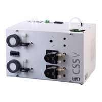
Gas Conditioning Unit, 19“, wall mount or portable in carrying case with software version 1.6
Brand: M&C
|
Category: Laboratory Equipment
|
Size: 5 MB
Table of Contents
Advertisement
M&C CSS Series Instruction Manual (36 pages)
19“ housing or wall mounting Gas Conditioning Unit
Brand: M&C
|
Category: Laboratory Equipment
|
Size: 1 MB
Table of Contents

M&C CSS Series Instruction Manual (31 pages)
Gas Conditioning Unit
Brand: M&C
|
Category: Analytical Instruments
|
Size: 5 MB
Table of Contents
Advertisement
M&C CSS Series Instruction Manual (31 pages)
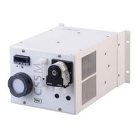
CSS-M/W wall mount
Brand: M&C
|
Category: Air Conditioner
|
Size: 1 MB
Table of Contents

M&C CSS Series Instruction Manual (25 pages)
Wall Mount Gas Conditioning Unit Mount
Table of Contents
Advertisement