M&C CSS Series Instruction Manual
Css-m/w wall mount
Hide thumbs
Also See for CSS Series:
- Instruction manual (59 pages) ,
- Instruction manual (36 pages) ,
- Instruction manual (31 pages)

Related Manuals for M&C CSS Series


Summary of Contents for M&C CSS Series
- Page 1 ® Gas Conditioning Unit Series CSS CSS-M/W wall mount Instruction Manual Version 1.02.01...
- Page 2 Dear customer, Thank you for buying our product. In this instruction manual you will find all necessary information about this M&C product. The information in the instruction manual is fast and easy to find, so you can start using your M&C product right after you have read the manual. If you have any question regarding the product or the application, please don’t hesitate to contact M&C or your M&C authorized distributor.
-
Page 3: Table Of Contents
Contents 1 General information ........................5 2 Declaration of conformity ......................5 3 Safety instructions ......................... 6 3.1 Intended use ..........................6 4 Warranty ............................7 5 Used terms and signal indications ....................7 6 Introduction ............................ 9 7 Application ............................. 9 8 ... - Page 4 List of Illustrations Figure 1 Scheme of gas flow ......................9 Figure 2 Dimensions CSS-M/W ......................11 Figure 3 Hose connections CSS-M/W ....................13 Figure 4 Electronic board CSS-M..................... 17 Figure 5 Replacement of the filter element and the O-ring ............... 19 Figure 6 ...
-
Page 5: General Information
Head Office M&C TechGroup Germany GmbH Rehhecke 79 40885 Ratingen Germany Telephone: 02102 / 935 - 0 Fax: 02102 / 935 - 111 E - mail: info@mc-techgroup.com www.mc-techgroup.com 1 GENERAL INFORMATION The product described in this manual has been built and tested in our production facility. All M&C products are packed to be shipped safely. -
Page 6: Safety Instructions
3 SAFETY INSTRUCTIONS Follow these safety directions and instructions regarding installation, commissioning and operation of the device: Read this manual before commissioning and operating the product. Make sure to follow all safety instructions. Installation and commissioning of electrical devices must be carried out only by qualified skilled personnel in compliance with the current regulations. -
Page 7: Warranty
4 WARRANTY In case of a device failure, please contact immediately M&C or your M&C authorized distributor. We have a warranty period of 12 months from the delivery date. The warranty covers only appropriately used products and does not cover the consumable parts. Please find the complete warranty conditions in our terms and conditions. - Page 8 Contains gas under pressure. Do not open container! Check pressure before opening container, and adjust pressure to atmospheric pressure. Wear protective gloves! Working with chemicals, sharp objects or extremely high temperatures requires wearing protective gloves. Wear safety glasses! Protect your eyes while working with chemicals or sharp objects. Wear safety glasses to avoid getting something in your eyes.
-
Page 9: Introduction
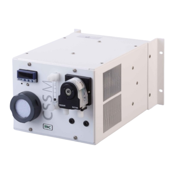
6 INTRODUCTION The gas conditioning unit CSS-M/W for wall mounting is a completely pre-assembled compact gas conditioning system working continuously and delivering a sample gas quantity of max. 70 Nl/h. The entire gas conditioning unit is housed in a compact and robust steel sheet case which ensures that the gas analyzes can be carried out quickly, safely and with a minimum amount of maintenance. -
Page 10: Technical Data
8 TECHNICAL DATA Gas Conditioning Unit Type CSS-M/W Range of adjustment: +2 to +15 °C [35.6 to 59 °F], factory Sample outlet dew point setting: +5 °C [41 °F] Dew point stability At constant conditions < ± 0.1 °C [± 0.18 °F] Sample inlet temperature **Max. -
Page 11: Description
9 DESCRIPTION Figure 2 shows the dimensions and construction of the CSS-M/W. 101,5 Netzkabel Signalkabel 37,75 47,5 Kondensat 372,5 Figure 2 Dimensions CSS-M/W Fine filter FPF-2-0,3GF Electronic controller Flow meter FM40 with sample gas outlet ... -
Page 12: Receipt Of Marchendise And Storage
10 RECEIPT OF MARCHENDISE AND STORAGE The gas sampling system CSS-M/W is a completely pre-installed unit. The scope of delivery includes furthermore: 25 x Filter elements (1 package) 1 x Connection cable 1 x Instruction Manual Please take the CSS-M/W and possible special accessories carefully out of the packaging material immediately after arrival, and compare the goods with the items listed on the delivery note;... -
Page 13: Supply Connections
12 SUPPLY CONNECTIONS 12.1 HOSE CONNECTIONS Sample gas inlet DN4/6 Sample gas outlet DN4/6 Mains cable Signal cable 3000mm 3000mm Condensate out DN3,2/6,4 350mm Figure 3 Hose connections CSS-M/W Do not mix up the hose connections; the connections are marked according to Figure 3. -
Page 14: Electrical Connections
Aggressive condensate is possible. Warning Chemical burns caused by aggressive media possible! Wear protective gloves and protective glasses! Wear proper protective clothing! 12.2 ELECTRICAL CONNECTIONS False supply voltage can damage the equipment. When connecting the Warning equipment, please ensure that the supply voltage is identical with the information provided on the model type plate! For the assembly of power installations with rated voltages up to 1000 V, the requirements of VDE 0100 and relevant standards and specifications... -
Page 15: Starting
13 STARTING Before starting the gas conditioning system, pay attention to the site-oriented and process-oriented precautions. Please check once again that the operating voltage (see type plate) corresponds to the supply voltage! Before connecting the equipment to the mains voltage, the main switch must be in position “0“. -
Page 16: Cooler Regulation
13.1 COOLER REGULATION Indication LED K1 LED K2 After starting up > 8 °C [46.4 °F] Off (Status alarm and pump Yellow light is (Ambient temp.) off) permanently on (cooling) 7.5 °C After approx. 10 min. Yellow light is on. Yellow light is In case no condensate alarm permanently on... -
Page 17: Figure 4 Electronic Board Css-M
Figure 4 Electronic board CSS-M.. www.mc-techgroup.com CSS-M/W | 1.02.01... -
Page 18: Closing Down
14 CLOSING DOWN The location for the gas conditioning unit must remain frost-free, even if the unit has been switched off. Note There are no special regulations to be observed if the gas conditioning unit CSS-M/W is to be closed down for a short period of time. -
Page 19: Replacement Of The Filter Element And The O-Ring
In order to protect downstream analyzers, the wet filter element must always be replaced in the event of a condensate ingress. Note The hose of the condensate pump SR25.2 should be checked every six months and, if necessary, replaced (see chapter 15.3.1). ... -
Page 20: Dismounting The Sample Gas Pump For Examination Or Maintenance
15.2 DISMOUNTING THE SAMPLE GAS PUMP FOR EXAMINATION OR MAINTENANCE For dismounting the sample gas pump N3 KPE : Dangerous voltage. Before any maintenance work is carried out on the Warning gas conditioning system, disconnect the unit from the mains! 1. -
Page 21: Mounting Instructions For Peristaltic Pump
Peristaltic pump is under pressure! Do not open housing! A peristaltic pump might be part of a system, which is under pressure. Check pressure before opening peristaltic pump, and adjust pressure to atmospheric pressure. Flexible tube, conveying belt, contact pulleys and contact springs are the only parts of the pump subject to wear. -
Page 22: Changing The Pump Tubing
15.3.2 CHANGING THE PUMP TUBING 1 Conveying belt 2 S-bolt 3 Tubing set 4 contact pulley 5 springs Figure 7 Changing the pump tubing For changing the pump tubing please proceed as follows: 1. Unplug the pump from the mains voltage. The device needs to be voltage free. Open tube connections at the pump;... -
Page 23: Changing Contact Pulleys And Springs
Figure 8 Different pump tube sizes 15.3.3 CHANGING CONTACT PULLEYS AND SPRINGS While mounting, make sure that the center of rotation and the driver are aligned. Use genuine spare parts only! Note Follow these instructions to change the contact pulley and springs: 1. -
Page 24: Figure 10 Check Of Axes And Rolls
6. Dismount roller axes and change contact pulleys. Take care that axes are not worn out by the springs and have damaged the dent at the axes front end. In case of abrasion the axes have to be changed (see Figure 10). The dent prevents rotation of the axis worn out... -
Page 25: Reassembly Of The Driver
15.3.4 REASSEMBLY OF THE DRIVER Reassemble the driver in reverse order: 1. Insert the roll carrier back into the pump head 2. Push the pump head with the roll carrier onto the motor shaft 3. Tighten the nuts of the pump head fastening (SW 5.5) While mounting, make sure that the center of rotation and the roll carrier (driver) are aligned. -
Page 26: Operating Of The Built-In Electronic Temperature Controller
16 OPERATING OF THE BUILT-IN ELECTRONIC TEMPERATURE CONTROLLER A new electronic temperature controller was installed in the housing of the conditioning unit CSS-M/W effective April 2022. 16.1 TEMPERATURE CONTROLLER VERSION UNTIL MARCH 2022 During normal operation, the display of the temperature regulator shows the actual cooling temperature. -
Page 27: Changing The Set Value
16.2.1 CHANGING THE SET VALUE Pressing the or key once causes the set setpoint to start flashing in the bottom line. Now the setpoint can be increased or reduced using the or keys. However, the value should not be set lower than +1 °C [33.8 °F], otherwise the heat exchanger is likely to freeze. -
Page 28: Proper Disposal Of The Device
Display Fault Possible cause Examination/Correction Pump defective Return instrument for repair to M&C. Pump works, Flow meter : but sample Needle valve is shut. gas flow is Sample probe or Set the desired flow rate on the needle valve. interrupted; sample hose clogged Loosen the sample hose from the sample gas inlet or line squeezed;... -
Page 29: Spare Part List
19 SPARE PART LIST Wear, tear and replacement part requirements depend on specific operating conditions. The recommended quantities are based on experience and are not binding. Gas Conditioning Unit Version CSS-M/W (C) Consumables, (R) Recommended Spare Parts and (S) Spare Parts Recommended quantity after operation of [years] Part No. -
Page 30: Appendix
20 APPENDIX Circuit diagram CSS-M/W For further product documentation, please see our webside: www.mc-techgroup.com Instruction manual peristaltic pump SR25.2, Instruction manual diaphragm pump series N Flowmeter FM 40 Data sheet: 9.2 Liquid alarm sensor LA1 Data sheet: 8.1 CSS-M/W | 1.02.01 www.mc-techgroup.com... -
Page 31: Circuit Diagram Css-M/W
Figure 13 Circuit diagram CSS-M/W www.mc-techgroup.com CSS-M/W | 1.02.01...
Need help?
Do you have a question about the CSS Series and is the answer not in the manual?
Questions and answers