Sign In
Upload
Manuals
Brands
Lucent Technologies Manuals
Gateway
PacketStar PSAX 4500
Lucent Technologies PacketStar PSAX 4500 Manuals
Manuals and User Guides for Lucent Technologies PacketStar PSAX 4500. We have
10
Lucent Technologies PacketStar PSAX 4500 manuals available for free PDF download: User Manual
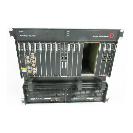
Lucent Technologies PacketStar PSAX 4500 User Manual (722 pages)
Multiservice Media Gateway
Brand:
Lucent Technologies
| Category:
Gateway
| Size: 5 MB
Table of Contents
Table of Contents
15
User Guide
1
Legal Notices, Safety, and Regulatory Information
3
Notices
3
Trademarks
3
Warranty Information
3
Software and Hardware Limited Warranties
3
Warranty Warnings
4
Regulatory Standards Compliance
5
Safety
5
Telecommunications
5
Regulatory Statements
6
FCC Part 15
6
FCC Part 68
6
USA Regulatory Statements
6
Underwriters Laboratories, UL 1950
7
Canadian Regulatory Statements
9
CE-Marking
9
European Union Regulatory Statement
9
Issue 8
9
Version 8
9
Japanese Regulatory Statements
13
VCCI
13
CISPR 22, en 55022, and AS/NZS-3548 Class a EMC Regulatory Statement
14
Jate
14
Table of Contents
15
List of Figures
29
List of Tables
35
Getting Started
41
Purpose of this Guide
41
Audience for this Guide
41
What You Should Know
41
Related Reading
42
Conventions
42
Other Publications
42
Printed Documents
42
Product Information Library
42
Text Types Used in this Document
42
Command Description Tables
43
Icons and Symbols
43
Text Conventions
43
Field Description Tables
44
Selecting Options, Fields, and Commands
44
Command Description Table Example
44
Field Description Table Example
44
Shortcut Keys for Navigating Console Interface Windows
45
Help Information
46
Main Menu Help Window
46
About Lucent Technologies
47
About the Packetstar PSAX Product Family
47
For more Information
47
History
47
PSAX 1000 Multiservice Media Gateway
47
Technical Support
47
PSAX 1250 Multiservice Media Gateway
48
PSAX 2300 Multiservice Media Gateway
48
PSAX 4500 Multiservice Media Gateway
49
System Responses to Selecting Options, Fields, or Commands
45
Hardware Description
51
Overview of this Chapter
51
System Features
51
System Hardware Components
51
DC Power Supply Module
51
Chassis
52
Functional Description
52
Packetstar PSAX 4500 Multiservice Media Gateway
52
Midplane
53
Module Slot Locations
53
Power Supply Modules
54
Data Flow through the Midplane
54
Physical Features
55
Stratum 3-4 Module
55
Timing Sources
56
Stratum 3-4 Module Status LED Indicators
56
Redundant System Timing
57
System Control and Monitoring
57
Timing Source Failures
57
Midplane Switching
58
Stratum 3-4 Module Traffic Switcher
58
CPU2 Module
59
System Redundancy
59
Optimizing Module Placement
60
PSAX 4500 Midplane Slot Structure
60
Chassis Specifications
61
Hardware Specifications
61
Chassis Hardware Specifications
61
Power Supply Module Specifications
62
System Environmental Specifications
62
CPU2 Module Specifications
63
Stratum 3-4 Module Specifications
63
Module Performance and Power Specifications
64
Packetstar I/O and Server Module Specifications
64
CPU2 Module Specifications
64
Physical Hardware Specifications for the Packetstar PSAX I/O and the Server Modules
64
Performance and Power Specifications for the PSAX Modules
64
System Features
69
Overview of this Chapter
69
System Capabilities
69
PSAX System Feature Highlights
69
PSAX System User Benefits
69
Interface Architecture
70
Connections Support
71
Soft Permanent Virtual Circuit (SPVC) Connections
71
SPVC Reconnection Prioritization
72
Sample SPVC Reconnection Prioritization Scheme
73
Sample User-Defined Priority Scheme for Reconnecting SPVC ATM IMA Links
73
Switched Virtual Circuit (SVC) Connections
74
Call States
75
SVC Functional Description
75
Circuit Emulation Service
78
Circuit Emulation Service for the Multiserial Module
78
SPVC Support for CES
78
User Interfaces
78
DS1 Service
79
Dynamic Bandwidth Circuit Emulation Service
79
Dynamic CAC
79
DS3 Service
80
HDLC Passthrough Bit Inversion
80
Interim Interswitch Signaling Protocol (IISP) Interface
80
Overview
80
Private Network-Network Interface (PNNI) 1.0
80
PNNI Features Supported by the PSAX Systems
81
PNNI Peer Group Dynamics
81
PNNI Hierarchies
82
PNNI Topology State Element (PTSE) Information
82
ATM Maintenance
84
PNNI Hierarchical Topology Showing Three Node Levels
84
ILMI over PNNI Overview
85
Integrated Link Management Interface (ILMI)
85
ATM Terminal Emulation
86
Inverse Multiplexing for ATM (IMA)
86
Load Balancing for IISP and PNNI
86
UNI 4.0 Signaling
86
Automatic Use of IMA Links
87
IMA Configuration Considerations
87
Frame Relay-To-ATM Interworking
88
Frame Relay-To-Frame Relay Interworking
88
FRF.5 Encapsulating Frames
88
FRF.8 Converting Frames
88
GR-303 Interface
88
Network Management
91
Aqueview ® Element Management System
92
Connection Gateway API
93
Connection Gateway API Overview
93
Multiservice Media Gateway Software Features
93
PSAX System as a TCP Client Device
94
PSAX System as a TCP Server Device
94
The PSAX 4500 as a TCP Client/Server for the Connection Gateway API
94
DS0A Non-Latched Loop Codes
95
DS1 ANI In-Line Codes for Loopbacks
95
N:1 Protection Scheme
96
PSAX 4500 System Traffic Protection Capabilities
96
N:1 Protection Scheme on the PSAX 4500 System
99
APS/MSP Protection on the Optical Modules
100
Interface Protection Group Feature
100
Typical Interface Protection Group Configuration
101
Alternate Rerouting Using Dual-Homed Pvcs
102
Automatic Rerouting with Dual-Homed Pvcs
103
Firmware Release Control
103
Forward Error Correction
104
H.248 Media Gateway Access Protocol
104
Rate Options
105
Internet Protocol (IP) Throttling
106
LANET Protocol
106
The Relationship between LANET and the OSI Model
107
LANET Frame Structure
108
OAM Cell Characteristics
109
Operations, Administration, and Maintenance (OAM)
109
Overview of OAM
109
OAM ATM Layer Flows
110
OAM Cell Fields
110
OAM F4 Flows
111
OAM F5 Flows
111
OAM Hierarchy
111
ATM Layer OAM Functions
112
OAM Activation/Deactivation Cells
113
Packet Pipe AAL5-To-AAL2 Wireless Trunking for Mobile Voice
113
Reduction in Post-Dial Delay
114
Traffic Management Using the Aqueman Algorithm
114
Trap Descriptions
114
Class of Service Descriptions
115
Multiservice Media Gateway System-Supported Service Classes
115
Cell Loss and Cell Delay Characteristics of ATM Service Classes
116
Class of Service Descriptions
116
CBR and VBR Service-Level Priorities
117
ATM Traffic Management (UPC Support)
118
Cell Bus Traffic Shaping
118
Cell Bus Traffic Shaping Happens on Egress to the Backplane
119
Cell Bus Traffic Shaping Using the Input Cell-Selection Algorithm
120
ATM Traffic Shaping
121
Channels
121
Overview of ATM Traffic Shaping
121
ATM Traffic Shaping for CBR and VBR-Rt
122
Task Summary for Implementing ATM Traffic Shaping
122
VBR ATM Traffic Shaping Priorities
122
ATM Traffic Shaping Table Sample Queue 1 Values
123
How the ATM Traffic Shaping Algorithm Works
123
Maximum Number of ATM Traffic-Shaped Connections
123
Formula for Determining the PCR of an ATM Traffic-Shaped Connection
124
V5.2 European IDLC
125
Virtual Interfaces
125
Echo Cancellation
126
Voice Compression
126
Voice Processing
126
Wireless Mobile Voice Backhaul
126
Packet Pipe AAL5-To-AAL2 Wireless Trunking from Cell Site to MSC for Mobile Voice
127
Virtual Routing
127
Traffic Flow Description
128
Virtual Router Concept
129
PSAX Module Features
130
Route Server Module and Example Configuration
130
Mapping ATM Service Classes to Multiservice Media Gateway System Priority Levels
117
Using VT100 Terminal Emulation
131
Overview of this Chapter
131
Setting up the Windows Hyperterminal Emulator
131
Connection Description Window
131
Connect to Window
132
COM 1 Properties Window
132
Connecting a Dialup Modem to the Chassis
133
Windows Hyperterminal Settings
133
Site-Specific Configuration
135
Overview of this Chapter
135
Logging Onto the System
135
PSAX 4500 Multiservice Media Gateway System Logon Window
136
Console Interface Main Menu Window
137
Field Descriptions for the Logon Window
137
Changing the System Password and Other User Options
138
User Options Window
139
Field Descriptions for the User Options Window
140
Console Interface Main Menu Options
142
Site-Specific Configuration Menu Options
142
Accessing the Site-Specific Menu
143
Configuring the System for Your Site
143
Configuring System Identification Information
144
Site-Specific Configuration Window
145
Rules for Configuring IP Addresses
146
ATM Addresses and OAM Properties
147
Configuring System Identification
147
Rules for Configuring IP Address Masks
147
Field Descriptions for the System Identification Panel
149
Configuring System Date and Time
150
Field Descriptions for the System Date and Time Panel
150
Configuring the PSAX System as a TCP Server or a TCP Client
151
TCP Server Configuration Window (PSAX System as a TCP Client)
152
TCP Server Configuration Window (PSAX System as a TCP Server)
152
Configuring SNMP Trap Destinations
153
Field Descriptions for the TCP Server Configuration Window
153
Field Descriptions for the SNMP Trap Destinations Panel
154
Configuring Call Control Resource Allocation
155
Setting the Configuration Values
155
Site-Specific Menu Window
156
Call Control Resource Allocation Configuration Window
157
Field Descriptions for the Call Control Resource Allocation Configuration Window
158
Field Descriptions for the Call Control Resource Allocation Configuration Window
159
Saving the Configuration and Rebooting the System
161
Diagnostics Menu
162
Remote Reboot Configuration Window
162
Backing up Configuration Data
163
Configuring DSP Resource Use
163
Configuring H.248 (Media Gateway Control Protocol)
163
Configuring TAS Module System-Wide Use
163
Enabling and Disabling System-Wide Features
163
Feature Turn On/Off Window
165
Rebooting Redundant or Non-Redundant PSAX System Cpus
167
Console Interface Main Menu Window
168
Console Interface Main Menu Window (Save Configuration Option Selected)
168
Remote Reboot Configuration Window (Primary Switchover Option Selected)
169
Configuring Interface Protection Groups
171
Setting up an Interface Protection Group ID
171
Interface Protection Feature Configuration Window
172
Protection Group Table Window
173
Protection Group Configuration Window
174
Field Descriptions for the Protection Group Configuration Window
174
Creating an Interface Protection Group
176
Interface Protection Table Window
176
Interface Protection Configuration Window
177
Field Descriptions for the Interface Protection Configuration Window
178
Internet Protocol (IP) Throttling
179
The IP Throttling Window (Disabled)
180
The IP Throttling Window (Enabled)
181
Field Descriptions for the IP Throttling Configuration Window
182
SNMP Trap Activation/Deactivation
184
Enabling and Disabling SNMP Trap Messages
185
Trap Activation Table Window
185
Trap Activation Table
186
Configuring N:1 Protection Groups
187
Field Descriptions for the Trap Activation Table Window
187
N to M Protection Feature Menu Window
188
N to M Protection Group Table Window
189
N to M Protection Group Configuration Window
190
Field Descriptions for the N to M Protection Group Configuration Window
191
N to M Protection Feature Menu Window
193
N to M Protection Table Window
194
Field Descriptions for the N to M Protection Table Window
194
N to M Protection Configuration Window
195
Field Descriptions for the N to M Protection Configuration Window
196
Using the Equipment Configuration Window
197
Sample Equipment Configuration Window on a PSAX 1000, PSAX 2300, or PSAX 4500
199
Field Descriptions for the Equipment Configuration Window
200
Alarm Status Descriptions for Modules on the Equipment Configuration Window
202
Configuring the Stratum 3-4 Module
202
Setting the Stratum Configuration Values
203
Stratum Configuration Window (Freerun)
203
Stratum Configuration Window (Linetiming Synchronization)
204
Field Descriptions for the Stratum Configuration Window
205
Switching the Line Timing Source
209
Alarm Status Values
210
Saving the Equipment Configuration Values and Logging off
210
Configuring PNNI
213
PNNI System-Wide Configuration
213
Configuring the PNNI Node
213
PNNI System-Wide Configuration Window
214
PNNI Node Table Window
216
PNNI Node Configuration Window
217
Field Descriptions for the PNNI Node Configuration Window
218
Configuring the PNNI Node Peer Group Leader
221
Modifying PNNI Configurations
221
Steps to Modify a Configured PNNI Node
221
PNNI Node PGL Configuration
222
Configuring the PNNI Node Timer
225
PNNI Node Timer Configuration
226
Field Descriptions for the PNNI Node Timer Configuration Window
226
Configuring the PNNI Node SVCC
228
PNNI Node SVCC Configuration
229
Field Descriptions for the PNNI Node SVCC Configuration Window
229
Configuring the PNNI Node Scope Mapping
230
PNNI Scope Mapping Configuration
231
Field Descriptions for the PNNI Scope Mapping Configuration Window
231
Configuring the PNNI Route Addresses
233
PNNI Route Address Table Window
234
PNNI Route Address Configuration Window
235
Configuring PNNI Metrics
238
PNNI Metrics Table Window
239
PNNI Metrics Configuration Window
240
Field Descriptions for the PNNI Metrics Configuration Window
241
Configuring PNNI Route TNS
243
PNNI Route TNS Table Window
243
Field Descriptions for the PNNI Route TNS Table Window
244
PNNI Route TNS Configuration Window
245
Viewing PNNI Map TNS Information
248
PNNI Map TNS Table
249
Field Descriptions for the PNNI Map TNS Table
250
PNNI Route TNS Table Window
251
Field Descriptions for the PNNI Map TNS Configuration Window
251
Configuring Summary Addresses
252
PNNI Summary Address Table Window
253
PNNI Summary Address Configuration Window
254
Field Descriptions for the PNNI Summary Address Configuration Window
255
Viewing the PNNI Map Information
256
PNNI Map Table Window
257
PNNI Map Information Window
258
Field Descriptions for the PNNI Map Information Window
258
PNNI Map Node Table Window
260
Viewing PNNI Map Node Information
260
PNNI Map Node Information Window
261
Field Descriptions for the PNNI Map Node Table Window
261
Field Descriptions for the PNNI Map Node Information Window
262
Viewing PNNI Map Address Information
264
PNNI Map Address Table Window
265
PNNI Map Address Information Window
266
Field Descriptions for the PNNI Map Address Table Window
266
Field Descriptions for the PNNI Map Address Entry Window
267
Viewing the PNNI Link Table
267
PNNI Link Table
268
PNNI Link Information Window
269
Field Descriptions for the PNNI Link Configuration Window
270
Viewing the PNNI SVCC RCC Information
273
PNNI Svccrcc Table
274
PNNI Svccrcc Information Window
275
Field Descriptions for the PNNI SVCC RCC Table Window
275
Field Descriptions for the PNNI SVCC RCC Configuration Window
276
Viewing the PNNI Neighbor Peer Table
277
PNNI Neighbor Peer Table Window
278
PNNI Neighbor Peer Information Window
279
Field Descriptions for the PNNI Neighbor Peer Configuration Window
279
Viewing the PNNI Neighbor Peer Port Table
281
PNNI Neighbor Peer Port Table
282
Field Descriptions for the PNNI Neighbor Peer Port Table Window
283
Viewing PNNI Topology State Element (PTSE) Information
283
PNNI PTSE Table
284
PNNI PTSE Information Window
285
Field Descriptions for the PNNI PTSE Table Window
285
Field Descriptions for the PNNI PTSE Information Window
286
PNNI System Statistics Window
288
Viewing PNNI System Statistics
288
Field Descriptions for the PNNI System Statistics Window
289
Configuring ATM Trunking
291
Overview of this Chapter
291
Configuring the Local IWF Node
291
Site-Specific Menu Window-ATM Trunking Configuration Option Selected
292
Site-Specific Menu Window
292
ATM Trunking Local Node Configuration Window
293
Field Descriptions for the ATM Trunking Local Node Configuration Window
294
Configuring a Remote IWF Node
295
ATM Trunking Remote IWF Table Window
296
ATM Trunking Remote IWF Configuration Window
297
Field Descriptions for the ATM Trunking Remote IWF Configuration Window
298
Adding a Signaling VCC Identifier
299
ATM Trunking Sig VCC Table Window
300
ATM Trunking Sig VCC Configuration Window
301
Field Descriptions for the ATM Trunking Sig VCC Table Window
301
Field Descriptions for the ATM Trunking Sig VCC Configuration Window
302
Adding a Bearer VCC Identifier
305
ATM Trunking Bearer VCC Table Window
306
Field Descriptions for the ATM Trunking Bearer VCC Table Window
306
ATM Trunking Bearer VCC Configuration Window
307
Field Descriptions for the ATM Trunking Bearer VCC Configuration Window
308
Adding a Narrowband Address
315
ATM Trunking Narrowband Routing Table Window
316
Field Descriptions for the ATM Trunking Narrowband Routing Table Window
316
Adding a Broadband Address
317
ATM Trunking Broadband Routing Table Window
318
Field Descriptions for the ATM Trunking Broadband Routing Table Window
318
Viewing ATM Trunking Information
319
ATM Trunking Data Channel Table
320
Configuring V5.2 European IDLC
323
Overview of the V5.2 European IDLC
323
V5.2 PSTN Implementation on the PSAX System
323
V5.2 ISDN Implementation on the PSAX System
326
PSTN Configuration
326
Enabling the V5 Feature on the Site Specific Configuration Window
326
Feature Turn On/Off Window
328
Setting Call Control Resource Allocation Values
330
Call Control Resource Allocation Configuration Window
332
Accessing the V5 Resource Allocation Configuration Window
337
Rebooting the Chassis
337
V5 Interface Configuration Window
337
V5 Interface Configuration Menu Window
338
V5 Resource Allocation Configuration Window
339
Field Descriptions for the V5 Resource Allocation Configuration Window
339
Accessing the V5 Interface Configuration Window
341
V5 Resource Allocation Configuration Window
342
V5 Interface Configuration Window
343
Field Descriptions for the V5 Interface Configuration Window
344
Accessing the V5 Variant Table
345
V5 Resource Allocation Configuration Window
346
Accessing the V5 Interface Variant Configuration Window
347
V5 Resource Allocation Configuration Window
348
Accessing the Data Link Configuration Table
351
V5 Data Link Configuration Table
351
Accessing the V5 Data Link Configuration Window
352
V5 Data Link Configuration Window
353
Accessing the V5 Physical C-Channel Configuration Table
354
V5 Physical C-Channel Configuration Table
355
Accessing the V5 Physical C-Channel Configuration Window
356
V5 Physical C-Channel Configuration Window
357
Field Descriptions for the V5 Physical C Channel Configuration Window
358
Accessing the V5 E1 Link Configuration Table
360
V5 E1 Link Configuration Table
360
Accessing the V5 E1 Link Configuration Window
361
V5 E1 Link Configuration Window
362
Field Descriptions for the V5 E1 Link Configuration Window
363
Accessing the V5 E1 Interface Configuration Window
364
The V5 E1 Interface Configuration Window Is Entirely Display-Only Fields
365
Field Descriptions for the V5 E1 Interface Configuration Window
365
Accessing the V5 Time Slot Table
366
Accessing the Data Link Configuration Table
367
V5 Time Slot Table
367
V5 Data Link Configuration Table
368
Accessing the V5 Data Link Configuration Window
369
V5 Data Link Configuration Window
370
Accessing the V5 User Port Table
373
V5 User Port Table
373
Accessing the V5 User Port Configuration Window, PSTN Port Type
374
V5 User Port Configuration Window for PSTN as Port Type
375
Field Descriptions for the V5 User Port Configuration Window
376
Accessing the User Port Configuration, ISDN Port Type
381
V5 User Port Configuration Window, Port Type ISDN Selected
382
Using System Diagnostics
383
Overview of this Chapter
383
Menu Option Descriptions for the Diagnostics Menu Window
383
Viewing System Status
384
Diagnostics Menu Window
385
System Information Window
386
Field Descriptions for the System Information Window
387
Running Cell Test Diagnostics
388
Cell Test Diagnostics Window
389
Field Descriptions for the Cell Test Diagnostics Window
390
Cell Test Payload Configuration Window
391
Field Descriptions for the Cell Test Payload Window
392
Rebooting PSAX Hardware Components
393
Removing Configuration Files
393
Unlocking a Telnet Session
394
Enabling OAM Loopback Functions
395
Operations Administration and Maintenance (OAM)
395
Unlock Shell / Ping Window
395
OAM Loopback Table Window
396
OAM Loopback Window
397
Field Descriptions for the OAM Loopback Window
398
OAM Activation and Deactivation
399
OAM Activate & Deactivate Table Window
400
OAM Activation -Deactivation Window
401
Field Descriptions for the OAM Activation-Deactivation Window
402
Backing up and Restoring PSAX System Files
405
Overview of this Chapter
405
Database Configuration Save and Restore Feature
405
Backing up System Database Files
406
Remote Database Operation
406
Remote Database Operation Window
406
Field Descriptions for the Remote Database Operation Window
407
Backing up Database Files Using FTP
410
Backing up Database Files Using Xmodem/Ymodem Transfer
411
Setting up for the File Transfer Process
411
Copying the Database Files to a Storage Medium
412
Software Version Configuration Window
412
Software Version Configuration Window (XMODEM/YMODEM File Transfer Selected)
412
XMODEM/YMODEM File Transfer Window (Send Options Panel Selected)
413
Restoring Database Files Using FTP
417
Restoring System Database Files
417
Rebooting the PSAX System
419
Restoring Database Files Using Xmodem/Ymodem File Transfer
420
Setting up for the File Transfer Process
420
Copying the Backup Files to the System
421
Rebooting the PSAX System
426
Restoring Backup Files to the Standby CPU2 Module
426
Connecting a Cable to the Standby (Backup) CPU Module
427
Upgrading PSAX System Software
429
Directory Structures
429
Overview of this Chapter
429
Saving Your Modified System Configuration
430
Preparing to Install a New Software Release
431
Tasks for Transferring Files to Your PSAX System
431
Upgrading Using the File Transfer Protocol Method
432
Migration of the Files During the PSAX System Upgrade
432
Setting up a Windows FTP Server
433
Upgrading the PSAX System Software Using FTP
433
SRD Download Configuration Window
435
Field Descriptions for the SRD Download Configuration Window
436
Error Status Code Values for the [Error Status] Field on the SRD Download Configuration Window
437
Determining Whether to Proceed with System Upgrade
441
Determining Whether to Save Your Current System Configuration before Upgrade
442
Setting up for the File Transfer Process
443
Setting up the Connection between the PC Workstation, the Local Modem, and the Telephone
443
Upgrading Using the Xmodem/Ymodem File Transfer Method
443
Downloading Software Files Using Xmodem/Ymodem
444
Setting up the Connection between the Modem and the PSAX System
444
Upgrading the PSAX System Software Using Xmodem/Ymodem Transfer
449
Firmware Version Control Window
450
Upgrading Firmware
450
Selecting Firmware Drivers
451
System Updating of Firmware Drivers
451
Upgrading I/O and Server Module Firmware
452
Firmware Version Control Window
453
The Software Version Configuration Window (Firmware Version Control Option Selected)
453
Field Descriptions for the Firmware Version Control Window
454
Falling Back to the Previous Software Release
455
Overview of this Appendix
457
Viewing Trap Log Information
457
A SNMP Trap Messages
458
D Reference Information. . . . . . . . . . . . . . . . . . . . . . . . . . . . . . . . . . . . . . .D-1
635
E PSAX Modules . . . . . . . . . . . . . . . . . . . . . . . . . . . . . . . . . . . . . . . . . . . . . . .E-1
671
SNMP Trap Messages
457
System Indicators
459
SNMP Trap Names and Descriptions with Associated MIB Object Names
460
System
460
AAL2 Configure Failure Codes
509
Definitions of MIB Objects Used for Trap Messages
509
Active Stratum Codes
511
Alarm Module Reason Codes
511
APS Failure Reason Codes
512
ARP Status Codes
512
ATM IMA Interface Status Codes
514
ATM Trunking Configuration Failure Codes
517
Module Operational Status Codes
521
Module Protection Status Codes
521
Module Type Codes
521
Chassis over Temperature Alarm Reason Codes
524
Firmware Download Reason Codes
526
LMI Operational Status Codes
529
GR-303 Interface Group Backup EOC Status Codes
530
GR-303 Interface Group Backup TMC Status Codes
531
GR-303 Interface Group Primary EOC Status Codes
531
GR-303 Interface Group Primary TMC Status Codes
532
GR-303 PPS Reason Codes
532
GR-303 PPS Source Codes
533
IMA GRP Channel End State Codes
533
IMA GRP Channel End State Codes
534
IMA GRP Channel Failure Status Codes
534
IMA Group Channel Status Codes
535
IMA GRP Channel Symmetry Codes
536
Interface Failure Reason Codes
536
Interface Type Codes
542
IP Interface Status Codes
544
IP Type Reason Codes
545
IPT Result Codes
545
IUA Application Server Process State Codes
547
Client/Server Option Codes
548
IUA Association State Codes
548
IUA Heartbeat Codes
549
Lim Status Codes
549
DS0A Line Status Codes
550
DS1 Line Status Alarms
550
Enhanced DS1 Line Status Codes
550
Enhanced E1 Line Status Codes
552
Ethernet Module Line Status Codes
554
Optical Modules Line Status Codes
555
LMI DLCI Operational Status Codes
556
Voice 2 Wire Office and Voice 2 Wire Station Line Status Codes
556
Ntom Protection Reason Codes
557
OAM Activation Deactivation Result Codes
558
OAM Test Failure Reason Codes
564
OC-3C APS Protection Line Signal Status Codes
565
OC-3C APS Reason Codes
565
OC-3C APS Selector State Codes
567
OC-3C APS Working Line Signal Status Codes
567
PGT Result Codes
568
Ping Status Reason Codes
569
PNNI Codes
569
Port Failure Reason Codes
570
Power Supply Reason Codes
571
PVC Failure Reason Codes
572
Remote Database Operation Error Status
590
Remote Database Operation Status
590
Remote Reboot Reason Codes
591
Remove Configuration Files Codes
593
Routing Status Codes
593
Sapphire Interface Address Fail Reason Codes
594
Save Configuration Reason Codes
594
SPVC Configuration Failure Codes
595
Static Route Codes
597
Stratum 3-4 Module Mode Codes
598
Stratum Configuration Modification Failure Reason Codes
598
Subchannel Status Codes
598
Switch Alarm Status Codes
599
Switch Fan Status Codes
600
TAS Module Compression Announcement Reason Codes
600
TAS Module Cache Memory Allocation Reason Codes
601
TAS Module Continuity Check Reason Codes
601
TAS Module Control Block Memory Reason Codes
601
TAS Module Memory Reason Codes
602
TAS Module Test Line Request Codes
602
Timing Reason Codes
603
Tone Announcement FTP Error Status Codes
603
Tone Announcement FTP Status Codes
604
Upgrade Software Copy Status Codes
604
Upgrade Software Error Status Codes
605
V5 Data Link Communication Path ID Codes
606
V5 Interface User Port Type Codes
607
Version Configuration Reason Codes
610
VPN Trap Status Codes
613
CONSOLE Connector Pin Assignments
615
Overview of this Appendix
615
RJ-12-To-DB25 Adapter Pin Assignments
615
RJ-12-To-DB9 Adapter Pin Assignments
615
B Pin Configurations
616
ETHERNET Connector Pin Assignments
616
ETHERNET Connector Pin Locations
616
Pin Assignments for the RJ-45 Connector on the Stratum 3-4 Module
617
C Configuring In-Band Management
619
Using the Direct Connection Configuration
620
Setting up ATM ARP Table Entries
621
Using the Routed Connection Configuration
622
Setting up Connections for a Routed Connection Configuration
623
Setting PVC Connections for Routed Connection Configuration
625
Using the Hybrid Connection Configuration
628
D Reference Information
633
ATM UNI Specification Cause Codes, Version 3.1
635
Industry Compliance Specifications
639
Connection Type by Interface Type Table
659
Interface Type by Input/Output Module Type Table
660
Interface Types by I/O Module Types
660
Module Alarm Status Table
665
Quality of Service (QOS) Class Tables
666
PSAX System-Supported Quality of Service Classes
667
Cell Loss and Cell Delay Characteristics of ATM Service Classes
668
Mapping ATM Service Classes to PSAX System Priority Levels
668
E PSAX Modules
669
Packetstar PSAX Modules
669
LIM 3–4 Module
671
Alarm Module
672
PSAX 4500 Alarm Module
673
Hardware Features
674
Software Features
675
Hardware Features
677
Software Features
678
Port Channelized STS-1E T1 Module
679
Hardware Features
680
Port Channelized DS3/STS-1E CES Protection Module
681
Port DS3 ATM Module
682
Port Unchannelized DS3 Frame Relay Module
683
Port DS3 IMA Module
684
Software Features
685
Port Enhanced DS1 Module
686
Software Features
687
Software Features
688
Software Features
689
Ethernet Module
690
Software Features
691
Port High-Density E1 Multiservice Module
692
Hardware Features
693
Software Features
694
Software Features
695
Port Medium-Density DS1 IMA Module
696
Port Medium-Density DS1/E1/DS0A CES Module
697
Port Multiserial Module
699
Circuit Emulation
700
Hardware Features
701
Software Features
702
Software Features
703
Software Features
704
Specifications
704
Port OC-12C/Stm-4C 1+1 APS/MSP Multimode and Single-Mode Modules
705
1-Port OC-12C/Stm-4C 1+1 APS/MSP SM and MM Modules Hardware Specifications
706
Software Features
706
Port OC-3C Multimode and Single-Mode Modules
707
Port OC-3C 1+1 APS Multimode and Single-Mode Modules
708
Software Features
709
Port STM-1 Multimode and Single-Mode Modules
710
Port STM-1 1+1 MSP Multimode and Single-Mode Modules
711
Software Features
712
Server Modules
713
Software Features
714
Hardware Features
715
Route Server Module
716
Hardware Features
717
Software Features
718
Advertisement
Lucent Technologies PacketStar PSAX 4500 User Manual (748 pages)
PSAX Multiservice Media Gateways
Brand:
Lucent Technologies
| Category:
Gateway
| Size: 10 MB
Table of Contents
Table of Contents
5
User Guide
1
Legal Notices, Safety, and Regulatory Information
3
Trademarks
3
Notices
3
Warranty Information
3
Regulatory Standards Compliance
4
Safety Information
4
Table of Contents
5
List of Figures
23
List of Tables
31
Getting Started
41
Purpose of this Guide
41
Audience for this Guide
41
What You Should Know
41
Related Reading
42
Other Publications
42
Printed Documents
42
Product Information Library
42
Conventions
42
Text Types Used in this Document
42
Text Conventions
42
Command Description Tables
43
Field Description Tables
43
Icons and Symbols
43
Command Description Table Example
43
Selecting Options, Fields, and Commands
44
Field Description Table Example
44
Help Information
45
System Responses to Selecting Options, Fields, or Commands
45
Shortcut Keys for Navigating Console Interface Windows
45
Main Menu Help Window
46
About Lucent Technologies
47
About the Packetstar PSAX Product Family
47
For more Information
47
History
47
PSAX 1000 Multiservice Media Gateway
47
Technical Support
47
PSAX 1000 Multiservice Media Gateway
51
Hardware Description
51
Front View of the PSAX 1000 Chassis
53
Rear View of the PSAX 1000 Chassis
53
PSAX 1000 Chassis Hardware Specifications
54
PSAX 1000 System Environmental Specifications
55
PSAX 1250 Multiservice Media Gateway
55
PSAX 1250 Multiservice Media Gateway(19-In.)
56
PSAX 1250 Multiservice Media Gateway (23-In.)
56
PSAX 1250 48.26-CM (19-In.) Chassis Backplane
58
PSAX 1250 58.42-CM (23-In.) Chassis Backplane
59
PSAX 1250 Chassis Hardware Specifications
59
PSAX 1250 System Environmental Specifications
60
Packetstar PSAX 2300 Multiservice Media Gateway
61
PSAX 2300 Chassis Hardware Specifications
63
PSAX 2300 System Environmental Specifications
63
Packetstar PSAX 4500 Multiservice Media Gateway
65
Data Flow through the PSAX 4500 Midplane
67
Chassis Hardware Specifications
67
PSAX 1000 Stratum 3-4/-48 V DC Power Supply Module
69
PSAX 1000 Stratum 3-4/110/220 V Ac Power Supply Module
70
Stratum 3-4/24 V DC Power Supply Module
71
PSAX 1000 Stratum 3-4/Power Supply Module Specifications
74
PSAX 1250 110 Vac, 220 Vac, and -48 V DC Power Supply Modules
76
PSAX 2300/4500 -48 V DC Power Supply Module
78
Functional Description
79
PSAX 1250 Stratum 3-4 Module
80
Stratum 3-4 Module Specifications
81
PSAX 2300 Stratum 3-4 Module Specifications
82
PSAX 4500 Stratum 3-4 Module
83
Stratum 3-4 Module Traffic Switcher
87
PSAX 1000 CPU3 Module
89
PSAX 1000 CPU3 Module Specifications
89
PSAX CPU4 Module
91
CPU4 Module Specifications
91
PSAX 1000 Fan/Alarm Module
92
PSAX 4500 Alarm Module
93
Example Configuration with the PSAX 4500 Alarm Module
93
Generating Central Office Alarms
94
Alarm Outputs
95
Generating Central Office Alarms (Example)
95
Alarm and PSAX 4500 Alarm Module Alarm Generation Criteria
96
Alarm Relay Operation
97
Fan/Alarm Module Alarm Generation Criteria
97
Alarm and PSAX 4500 Alarm Module ALARM Connector Configuration
98
Chapter 2 Hardware Description
98
Fan/Alarm Module ALARM Connector Configuration
99
Audible Alarm Cutoff (ACO)
100
Generating Alarms
100
Monitoring and Reporting on External Events
101
Monitoring and Reporting on External Events (Example)
101
Control Outputs
102
Control Output Relay Configuration
102
Remote Status Inputs
103
Activating Supplemental Air Conditioning
103
Monitoring and Reporting on Door Sensors
103
6-Port Multiserial Modules
104
I/O and Server Modules
104
Optimizing I/O and Server Module Placement
104
PSAX 1000 Chassis
104
PSAX 4500 Chassis
104
PSAX 4500 Midplane Slot Structure
104
Module Performance and Power Consumption
105
Performance and Power Specifications for the PSAX Modules
106
Feature Highlights
113
Overview of this Chapter
113
System Capabilities
113
System Features
113
User Benefits
113
Connections Supported
115
Interface Architecture
115
Permanent Virtual Circuit (PVC) Connections
115
Soft Permanent Virtual Circuit (SPVC) Connections
115
SPVC Reconnection Priority Scheme
116
Sample SPVC Reconnection Prioritization Scheme
117
Sample User-Defined Priority Scheme for Reconnecting SPVC ATM IMA Links
117
Modification of Parameters for Active SPVC Connections
118
SPVC Auto-Restart
118
Switched Virtual Circuit (SVC) Connections
118
Call States
119
SVC Functional Description
119
SVC Call State Transition Messages
120
System
121
User Interfaces
121
Circuit Emulation Service
122
Circuit Emulation Service for the 6-Port Multiserial Module
122
Dynamic Bandwidth Circuit Emulation Service
122
SPVC Support for CES
122
DS1 Service
123
DS3 Service
123
Dynamic CAC
123
HDLC Passthrough Bit Inversion
124
Interim Interswitch Signaling Protocol (IISP) Interface
124
Overview
124
Private Network-Network Interface (PNNI) 1.0
124
PNNI Features Supported by the PSAX Systems
125
PNNI Peer Group Dynamics
126
PNNI Topology State Element (PTSE) Information
126
PNNI Hierarchies
127
ATM Maintenance
128
PNNI Hierarchical Topology Showing Three Node Levels
128
Integrated Link Management Interface (ILMI)
129
Path and Connection Trace
129
ATM Terminal Emulation
130
ILMI over PNNI Overview
130
Load Balancing for IISP and PNNI
130
ATM UNI 4.0 Signaling
131
Automatic Use of IMA Links
131
IMA Configuration Considerations
131
Inverse Multiplexing over ATM (IMA)
131
Frame Relay-To-ATM Interworking
133
FRF.5 Encapsulating Frames
133
FRF.8 Converting Frames
133
Inverse Address Resolution Protocol (ARP)
133
Frame Relay-To-Frame Relay Interworking
134
GR-303 Interface
134
CAS Refresh Rates in the On-Hook State
135
Fax/Modem Master/Slave Support
135
Dynamic Bandwidth Allocation
136
Idle Channel Suppression Support for the Cellpipe IAD
136
Interoperability
136
DBA-Controlled Backplane Traffic
137
Network Management
138
Network Management Options
138
Simple Network Management Protocol Version 3
139
Navis EMS-PSAX System
140
Bulk Statistics Collection
141
Connection Gateway API
141
Connection Gateway API Overview
141
PSAX System Software Features
141
PSAX System as a TCP Client/Server for the Connection Gateway API
142
PSAX System as a TCP Client Device
142
Fractional PRI Support
143
PNNI Support
143
PSAX System as a TCP Server Device
143
DS0A Non-Latched Loop Codes
144
DS1 ANI In-Line Codes for Loopbacks
144
N:1 Traffic Protection with the PSAX 4500 System
145
PSAX System Traffic Protection Capabilities
145
N:1 Traffic Protection Scheme on the PSAX 4500 System
148
1:1 Traffic Protection with the PSAX 1000 System
149
1:1 Protection Scheme on the PSAX 1000 System
151
1:1 Traffic Protection with the PSAX 24-Port RJ Protection Patch Panel
152
1:1 Protection Scheme on the PSAX System
154
APS/MSP Protection on the Optical Modules
155
Line Defect Protection
155
Interface Protection Group with ATM Interfaces
156
Typical Interface Protection Group Configuration
157
Alternate Rerouting Using DHPVC
158
Firmware Release Control
159
Automatic Traffic Rerouting Using Dhpvcs
159
Forward Error Correction
160
Forward Error Correction Automatic Rate Options
161
H.248 Media Gateway Access Protocol
162
Interface and Connection Naming
162
Internet Protocol (IP) Throttling
164
LANET Protocol
164
Relationship between LANET and the OSI Model
165
Operations, Administration, and Maintenance (OAM)
166
Overview of OAM
166
LANET Frame Structure
166
OAM Cell Characteristics
167
OAM Cell Fields
168
OAM ATM Layer Flows
169
OAM F4 Flows
170
OAM F5 Flows
170
OAM Hierarchy
170
Modules Supporting OAM Flows
171
PSAX Modules Supporting OAM Flows
171
ATM Layer OAM Functions
172
OAM Activation/Deactivation Cells
173
Packetpipe AAL5-To-AAL2 Wireless Trunking for Mobile Voice
174
SNMP Trap Descriptions
174
CBR and VBR Service-Level Priorities
175
Traffic Management Using the Aqueman Algorithm
175
ATM Traffic Management
176
Guaranteed Frame Rate
176
UPC Support
177
Usage Parameter Control
177
Adjustable Queue Depth
178
ATM Traffic Shaping
178
Early Packet Discard
178
Overview of ATM Traffic Shaping
178
Configuring ATM Traffic Shaping
179
Sample ATM Traffic Shaping Flow
179
ATM Traffic Shaping Priorities
180
Task Summary for Implementing ATM Traffic Shaping
180
ATM Traffic Shaping Capabilities by PSAX Module
181
ATM Traffic Shaping for CBR and VBR-Rt
181
Connection Egress Priority on PSAX Modules Supporting ATM Traffic Shaping
181
Maximum Number of ATM Traffic-Shaped Connections
181
ATM Traffic Management Capabilities by Module
182
Virtual Interfaces
183
Sample Uses of Virtual Interfaces
184
Combining the UPC Feature and Either the TS or VI Feature on a Connection
185
ATM Traffic Shaping, UPC Support, and VI Support Configuration Compatibility
185
Packetpipe AAL5-To-AAL2 Wireless Trunking from Cell Site to MSC for Mobile Voice
189
Virtual Router Concept
190
Route Server and Example Configuration
191
Enhanced Router and Example Configuration
191
End-To-End Continuity Check
192
System
194
System Security
198
PSAX System Access Authentication Via RADIUS Servers
199
Connection Description Window
204
Starting the Hyperterminal Program
204
Connect to Window
205
COM1 Properties Window
205
Windows Hyperterminal Settings
206
PSAX System Logon Window Field Descriptions
211
Console Interface Main Menu Options and Commands
213
User Options Window-Authentication Mode Hybrid Selected
216
User Options Window Field Descriptions (RADIUS Server Fields)
218
Permissions for PSAX-Defined Usernames
220
User Options Window-Logged on as Username Readwrite
221
User Options Window-Logged on as Username Readonly
222
User Options Fields)
222
User Options Window Field Descriptions
222
ASCII Characters Permitted for Use in Passwords
224
Site-Specific Menu Window (no System Options Configured)
227
Site-Specific Menu Options Descriptions
228
System Identification Panel on the Site-Specific Configuration Window Field Descriptions
231
Site-Specific Configuration Window
234
Master ATM Address and OAM Related Data Panel on the Site-Specific Configuration Window Field Descriptions
234
Site-Specific Configuration Window Commands
234
Window Field Descriptions
234
System Related Data Panel on the Site-Specific Configuration Window
236
System Date and Time Panel on the Site-Specific Configuration Window
237
TCP Server Configuration Window Commands
239
TCP Server Configuration Window Field Descriptions
240
Site-Specific Menu Window
242
Call Control Resource Allocation Configuration Window Commands
243
Call Control Resource Allocation Configuration Window Field Descriptions
243
Call Control Resource Allocation Configuration Window Field Descriptions
244
Diagnostics Menu
251
Sample IUA Layer Configuration for the OMG and TMG Sides
261
IUA Layer Configuration Window Commands
261
IUA Layer Configuration Window Field Descriptions
261
Interface Protection Feature Configuration Window
263
Protection Group Table Window
264
Interface Protection Feature Configuration Window Commands
264
Protection Group Table Window Commands
264
Protection Group Configuration Window
265
Protection Group Configuration Window Commands
265
Protection Group Configuration Window Field Descriptions
265
Interface Protection Table Window
267
Interface Protection Table Window Commands
267
Interface Protection Configuration Window Commands
268
Interface Protection Configuration Window
269
Interface Protection Configuration Window Field Descriptions
269
N to M Protection Feature Menu Window (N:1 Protection)
270
N to M Protection Group Table Window (N:1 Protection)
271
N to M Protection Group Table Window Commands
271
N to M Protection Group Configuration Window (N:1 Protection)
272
N to M Protection Group Configuration Window (1:1 Protection)
272
N to M Protection Group Configuration Window Commands
273
N to M Protection Group Configuration Window Field Descriptions
273
N to M Protection Feature Menu Window
275
N to M Protection Table Window Commands
277
N to M Protection Table Window Field Descriptions
277
N to M Protection Configuration Window
279
N to M Protection Configuration Window Commands
279
N to M Protection Configuration Window Field Descriptions
279
The IP Throttling Window (Disabled)
282
The IP Throttling Window (Enabled)
282
IP Throttling Configuration Window Commands
282
IP Throttling Configuration Window Field Descriptions
283
Trap Activation Table Window Commands
287
Trap Activation Table
288
Trap Activation Table Window Field Descriptions
288
Bulk Statistics Configuration Window
290
Bulk Statistics Configuration Window Commands
290
Bulk Statistics Configuration Window Field Descriptions
290
Sample Equipment Configuration Window on a PSAX 1000 System
293
Sample Equipment Configuration Window on a PSAX 1250
293
Sample Equipment Configuration Window on a PSAX 2300 or PSAX 4500 System
294
Sample Equipment Configuration Window on a PSAX 1000, PSAX 2300, or PSAX 4500 System
294
Equipment Configuration Window Commands
295
Equipment Configuration Window Field Descriptions
296
Module Alarm Status Descriptions on the Equipment Configuration Window
298
Stratum Configuration Window (Freerun)
300
Stratum Configuration Window (Linetiming Synchronization)
300
Stratum Configuration Window Commands
301
Stratum Configuration Window Field Descriptions
301
Save Configuration [Modified] (before Saving)
309
Messages Generated after the Save Configuration Process
309
PNNI System-Wide Configuration Menu Window
312
PNNI System-Wide Configuration Window Commands
312
PNNI Node Table Window Commands
314
PNNI Node Table Window Field Descriptions
314
PNNI Node Configuration Window Commands
316
PNNI Node Configuration Window Field Descriptions
316
Modifying a Configured PNNI Node
319
PNNI Node PGL Configuration
320
PNNI Node PGL Configuration Window Field Descriptions
320
PNNI Node Timer Configuration Window
323
PNNI Node Timer Configuration Window Field Descriptions
323
PNNI Node SVCC Configuration Window
326
PNNI Node SVCC Configuration Window Field Descriptions
326
PNNI Scope Mapping Configuration
328
PNNI Scope Mapping Configuration Window Commands
328
PNNI Scope Mapping Configuration Window Field Descriptions
328
PNNI Route Address Table Window
331
PNNI Route Address Table Window Commands
331
PNNI Local Route Address through Interface Index Window
332
PNNI Route Address Table Window Field Descriptions
332
PNNI Route Address Configuration Window
333
PNNI Local Route Address through Interface Index Window Commands
333
PNNI Route Address Configuration Window Commands
333
PNNI Route Address Configuration Window Field Descriptions
334
PNNI Metrics Table Screen
337
PNNI Metrics Table Screen Commands
337
PNNI Metrics Configuration Screen
338
PNNI Metrics Table Screen Field Descriptions
338
PNNI Metrics Configuration Screen Commands
339
PNNI Metrics Configuration Screen Field Descriptions
339
PNNI Summary Address Table Window
341
PNNI Summary Address Table Window Commands
342
PNNI Summary Address Table Window Field Descriptions
342
PNNI Summary Address Configuration Window
343
PNNI Summary Address Configuration Window Commands
343
PNNI Summary Address Configuration Window Field Descriptions
343
PNNI Map Table Window
345
PNNI Map Table Window Commands
346
PNNI Map Table Window Field Descriptions
346
PNNI Map Information Window
347
PNNI Map Information Window Commands
347
PNNI Map Information Window Field Descriptions
347
PNNI Map Node Table Window Commands
349
PNNI Map Node Table Window
350
PNNI Map Node Information Window Command
350
PNNI Map Node Table Window Field Descriptions
350
PNNI Map Node Information Window
351
PNNI Map Node Information Window Field Descriptions
351
PNNI Map Address Table Window
354
PNNI Map Address Table Window Commands
354
PNNI Map Address Table Window Field Descriptions
354
PNNI Map Address Information Window
355
PNNI Map Address Information Window Commands
355
PNNI Map Address Information Window Field Descriptions
355
PNNI Link Table Window
357
PNNI Link Table Window Commands
357
PNNI Link Information Window
358
PNNI Link Information Window Commands
358
PNNI Link Table Window Field Descriptions
358
PNNI Link Configuration Window Field Descriptions
359
PNNI Svccrcc Table Window
362
PNNI Svccrcc Table Window Commands
362
PNNI SVCC RCC Table Window Field Descriptions
363
PNNI SVCC RCC Information Window Commands
364
PNNI SVCC RCC Information Window Field Descriptions
364
PNNI Neighbor Peer Table Window Commands
366
PNNI Neighbor Peer Table Window
367
PNNI Neighbor Peer Information Window Commands
367
PNNI Neighbor Peer Table Window Field Descriptions
367
PNNI Neighbor Peer Information Window
368
PNNI Neighbor Peer Information Window Field Descriptions
368
PNNI Neighbor Peer Port Table Window
370
PNNI Neighbor Peer Port Table Window Commands
370
PNNI Neighbor Peer Port Table Window Field Descriptions
371
PNNI PTSE Table Window
372
PNNI PTSE Table Window Commands
372
PNNI PTSE Information Window
373
PNNI PTSE Table Window Field Descriptions
373
PNNI Route TNS Table Window Commands
373
PNNI PTSE Information Window Field Descriptions
374
PNNI System Statistics Screen Window
375
PNNI System Statistics Screen Window Commands
376
PNNI System Statistics Window Field Descriptions
376
Site-Specific Menu Window-ATM Trunking Configuration Option Selected
381
ATM Trunking Local Node Configuration Window
381
ATM Trunking Local Node Configuration Window Commands
382
ATM Trunking Local Node Configuration Window Field Descriptions
382
ATM Trunking Remote IWF Table Window
384
ATM Trunking Remote IWF Table Window Commands
384
ATM Trunking Remote IWF Table Window Field Descriptions
384
ATM Trunking Remote IWF Configuration Window Commands
385
ATM Trunking Remote IWF Configuration Window Field Descriptions
386
ATM Trunking Sig VCC Table Window
388
ATM Trunking Signal VCC Table Window Commands
388
ATM Trunking Signal VCC Table Window Field Descriptions
388
ATM Trunking Sig VCC Configuration Window
389
ATM Trunking Signal VCC Configuration Window Commands
389
ATM Trunking Signal VCC Configuration Window Field Descriptions
390
ATM Trunking Bearer VCC Table Window
393
ATM Trunking Bearer VCC Table Window Commands
393
ATM Trunking Bearer VCC Table Window Field Descriptions
394
ATM Trunking Bearer VCC Configuration Window
395
ATM Trunking Bearer VCC Configuration Window Commands
395
ATM Trunking Bearer VCC Configuration Window Field Descriptions
396
ATM Trunking Bearer VCC Parameters Window
403
ATM Trunking Bearer VCC Parameters Window Commands
404
ATM Trunking Bearer VCC Parameters Window Field Descriptions
404
ATM Trunking Narrowband Routing Table Window
408
ATM Trunking Narrowband Routing Table Window Commands
408
ATM Trunking Narrowband Routing Table Window Field Descriptions
408
ATM Trunking Broadband Routing Table Window
409
ATM Trunking Broadband Routing Table Window Commands
410
ATM Trunking Broadband Routing Table Window Field Descriptions
410
ATM Trunking Data Channel Table
411
ATM Trunking Data Channel Table Window Commands
411
ATM Trunking Data Channel Table Window Field Descriptions
411
ATM Trunking Bearer VCC Profile Config Table Window
413
ATM Trunking Bearer VCC Profile Config Table Window Commands
413
ATM Trunking Bearer VCC Profile Config Table Window Field Descriptions
413
ATM Trunking Bearer VCC Profile Configuration Window
414
ATM Trunking Bearer VCC Profile Configuration Window Commands
414
ATM Trunking Bearer VCC Profile Configuration Window Field Descriptions
414
V5.2 Voice Switch Interoperability
420
Pstn Configuration
421
V5.2 IAD Interoperability
421
Call Control Resource Allocation Configuration Window Commands
427
V5 Configuration Window
435
V5 Interface Configuration Menu Window Commands
435
V5 Resource Allocation Configuration Window
436
V5 Resource Allocation Configuration Window Commands
436
V5 Resource Allocation Configuration Window Field Descriptions
436
V5 DSP over Subscription Table Window
439
V5 DSP over Subscription Table Window Commands
439
V5 DSP over Subscription Table Window Field Descriptions
440
V5 DSP Resource Pool over Subscription Configuration Window
441
V5 DSP Resource Pool over Subscription Configuration Window Commands
441
V5 DSP Resource Pool over Subscription Configuration Window Field Descriptions
442
V5 Interface Table Window
443
V5 Interface Table Window Commands
443
V5 Interface Table Window Field Descriptions
444
V5 Interface Configuration Window Commands
445
V5 Interface Configuration Window
446
V5 Interface Configuration Window Field Descriptions
446
V5 Intf Variant Table Window
448
V5 Interface Variant Table Window Field Descriptions
448
V5 Intf Variant Table Window Commands
448
V5 Interface Variant Configuration Window Commands
450
V5 Interface Variant Configuration Window
451
V5 Interface Variant Configuration Window Field Descriptions
451
V5 Physical C-Channel Configuration Table Window
453
V5 Physical C-Channel Configuration Table Window Commands
453
V5 Physical C-Channel Configuration Table Window Field Descriptions
454
V5 Physical C-Channel Configuration Window
455
V5 Physical C-Channel Configuration Window Commands
455
V5 Physical C Channel Configuration Window Field Descriptions
456
V5 E1 Link Configuration Table Window
458
V5 E1 Link Configuration Table Window Commands
458
V5 E1 Link Configuration Table Window Field Descriptions
459
V5 E1 Link Configuration Window
460
V5 E1 Link Configuration Window Field Descriptions
460
V5 E1 Interface Configuration Window
462
V5 E1 Interface Configuration Window Field Descriptions
463
V5 Time Slot Table
464
V5 Timeslot Table Window Commands
464
V5 Data Link Configuration Table
465
V5 Data Link Configuration Table Window Commands
465
V5 Data Link Configuration Table Window Field Descriptions
465
V5 Data Link Configuration Window
466
V5 Data Link Configuration Window Commands
466
V5 Data Link Configuration Window Field Descriptions
467
ATM Trunking Remote IWF Configuration Window
468
V5 User Port Table
469
V5 User Port Table Window Commands
469
V5 User Port Configuration Window for PSTN as Port Type
471
V5 User Port Configuration Window Commands
471
V5 User Port Configuration Window Field Descriptions
472
V5 User Port Configuration Window, Port Type ISDN Selected
477
V5 B Channels CID Table Window
478
V5 B Channel CID Table Window Commands
478
V5 B Channel CID Table Window Field Descriptions
478
Snmp Overview
479
Site-Specific Menu Window, SNMP Agent Selected
481
SNMP Agent System-Wide Configuration Window, Non-Root User View
481
SNMP Agent System-Wide Configuration Window, Root User View
482
SNMP Agent System-Wide Configuration Window Menu Options
482
Community String Table Window
483
Community String Table Window Commands
483
Community String Configuration Window
484
Community String Configuration Window Commands
484
Community String Table Window Field Descriptions
484
Community String Configuration Window Field Descriptions
485
Default USM User Information
485
Usm User Table Window
486
Usm User Table Window Commands
487
Usm User Table Window Field Descriptions
487
Usm User Creation Window
488
Usm User Creation Window Commands
488
Usm User Creation Window Field Descriptions
488
Usm User Key Change Configuration Window
490
Usm User Key Change Configuration Window Commands
490
Usm User Key Change Configuration Window Field Descriptions
491
Default VACM Access Groups
492
Vacm Access Table Window
493
Vacm Access Table Window Commands
493
Vacm Access Table Window Field Descriptions
494
Vacm Access Configuration Window Commands
495
Vacm Access Configuration Window
496
Vacm Access Configuration Window Field Descriptions
496
Default VACM Access Group Assignments
499
Valid VACM Group Assignment for USM Security Level
500
Vacm Security to Group Table Window
501
Vacm Security to Group Table Window Commands
501
Vacm Security to Group Table Window Field Descriptions
502
Vacm Security to Group Configuration Window
503
Vacm Security to Group Configuration Window Commands
503
Vacm Security to Group Configuration Window Field Descriptions
504
Notification Table Window
506
Notification Configuration Window
507
Notification Table Window Commands
507
Notification Table Window Field Descriptions
507
Notification Configuration Window Commands
508
Notification Configuration Window Field Descriptions
508
ATM UNI Interface ATM Security Window
513
ATM UNI Interface ATM Security Window Commands
513
ATM UNI Interface ATM Security Window Field Descriptions
514
ATM UNI Interface ATM Security Configuration Window (Integrity Security Service Only)
515
ATM UNI Interface ATM Security Configuration Window Field Descriptions
516
ATM UNI Interface ATM Security Configuration Window Commands
516
Security Services
520
ATM UNI Interface ATM Security Statistics Window
520
ATM UNI Interface ATM Security Statistics Window Commands
520
ATM UNI Interface ATM Security Statistics Window Field Descriptions
521
PNNI Node Configuration Window
524
ATM PNNI SVCC RCC Security Configuration Window (Integrity Security Service Only)
525
ATM PNNI SVCC RCC Security Configuration Window
525
And Confidentiality Security Services)
526
ATM PNNI SVCC RCC Security Configuration Window Commands
526
ATM PNNI SVCC RCC Security Configuration Window Field Descriptions
527
ATM PNNI SVCC RCC Security Statistics Window
531
ATM PNNI SVCC RCC Security Statistics Window Commands
531
ATM PNNI SVCC RCC Security Statistics Window Field Descriptions
532
ATM PNNI Interface ATM Security Window
535
ATM PNNI Interface ATM Security Window Commands
535
ATM PNNI Interface ATM Security Window Field Descriptions
536
ATM PNNI Interface ATM Security Configuration
537
Window - Signaling PVC (Integrity Security Service Only)
537
ATM PNNI Interface ATM Security Configuration Window - Signaling PVC (both Integrity Security and Confidentiality Services)
538
ATM PNNI Interface ATM Security Configuration - Signaling PVC
538
Window Commands
538
ATM PNNI Interface ATM Security Configuration - Signaling PVC Window Field Descriptions
539
ATM PNNI Interface ATM Security Statistics - Signaling PVC Window
542
ATM PNNI Interface ATM Security Statistics - Signaling PVC Window Commands
543
ATM PNNI Interface ATM Security Statistics - Signaling PVC Window Field Descriptions
543
ATM PNNI Interface ATM Security Configuration - Routing PVC Window (Integrity Security Service Only)
546
ATM PNNI Interface ATM Security Configuration - Routing PVC Window (both Integrity Security and Confidentiality Services)
546
ATM PNNI Interface ATM Security Configuration - Routing
547
ATM PNNI Interface ATM Security Configuration - Routing PVC
547
PVC Window Commands
547
ATM PNNI Interface ATM Security Statistics - Routng PVC Window
551
ATM PNNI Interface ATM Security Statistics - Routing PVC Window Commands
551
ATM PNNI Interface ATM Security Statistics - Routing PVC Window Field Descriptions
552
ATM Security Agents Table Window (Populated)
554
ATM Security Agents Table Window Commands
555
ATM Security Agents Table Window Field Descriptions
555
ATM Security Statistics Window
557
ATM Security Statistics Window Commands
557
ATM Security Statistics Window Field Descriptions
558
Diagnostics Menu Window
562
Diagnostics Menu Window Commands
563
System Information Window
564
System Information Window Commands
564
System Information Window Field Descriptions
565
Module Connection Count Window
568
Module Connection Count Table Window Commands
568
Module Connection Count Table Window Field Descriptions
568
Cell Test Diagnostics Window
570
Cell Test Diagnostics Window Commands
570
Cell Test Diagnostics Window Field Descriptions
571
Cell Test Payload Configuration Window
572
Cell Test Payload Configuration Window Commands
572
Cell Test Payload Configuration Window Field Descriptions
573
Remote Reboot Configuration Window Commands
576
Unlock Shell / Ping Window
578
OAM Loopback Table Window Commands
580
OAM Loopback Table Window
581
OAM Loopback Window
581
OAM Loopback Table Window Field Descriptions
581
OAM Loopback Window Commands
582
OAM Loopback Window Field Descriptions
582
OAM Activate & Deactivate Table Window
585
OAM Activate & Deactivate Table Window Commands
585
OAM Activation - Deactivation Window
586
OAM Activation - Deactivation Window Commands
586
OAM Activation - Deactivation Window Field Descriptions
586
Tasks for Copying Database Configuration Files between the PSAX System and a Remote Storage Medium
594
Remote Database Operation Window
596
Remote Database Operation Window Commands
596
Remote Database Operation Window Field Descriptions
596
PSAX System Configuration Files
600
Software Version Configuration Window
602
XMODEM/YMODEM File Transfer Window (Send Options Panel Selected)
603
XMODEM/YMODEM File Transfer Window Commands
603
XMODEM/YMODEM File Transfer Window Commands
604
XMODEM/YMODEM File Transfer Window Field Descriptions
604
XMODEM/YMODEM File Transfer Window Field Descriptions
605
Connecting a Cable to the Standby (Backup) CPU Module
611
Tasks for Transferring Files to Your PSAX System
614
SRD Download Configuration Window
617
SRD Download Configuration Window Commands
618
SRD Download Configuration Window Field Descriptions
618
Error Status Code Values for the [Error Status] Field on the SRD Download Configuration Window Field Descriptions
619
Determining Whether to Proceed with System Upgrade
622
Migration of the Files During the PSAX System Upgrade
623
Determining Whether to Save Your Current System Configuration before Upgrade
624
Length of Time Required for Firmware Downloading
626
Setting up the Connection between the Modem and the PSAX System
628
Setting up the Connection between the PC Workstation, the Local Modem, and the Telephone Jack
628
The Software Version Configuration Window (Firmware Version Control Selected)
636
Firmware Version Control Window
638
Firmware Version Control Window Commands
638
Firmware Version Control Window Field Descriptions
639
AC Power Supply Connector Pin Configuration
643
AC Power Supply Connector Pin Assignments
643
Cpun Module CONSOLE Connector Pin Assignments
644
ETHERNET1 and ETHERNET2 Connector Pin Locations
645
Cpun Module ETHERNET1 and ETHERNET2 Connector Pin Assignments
645
RJ-12-To-DB9 Adapter Pin Assignments
645
Attaching the External Clock Connector
646
RJ-12-To-DB25 Adapter Pin Assignments
646
Stratum 3-4 Module Connector Pin Assignments
647
Stratum 3-4 Module RJ-45 Connector Pin Assignments
647
ALARM Connector Pin Locations on the Fan/Alarm Module
648
ALARM Cable with 26-Pin Connector and Pigtail
648
(Comcode 300164290
648
ALARM Connector Pin Assignments and Cable Pigtail Color Code
648
ALARM Connector Pin Assignments and Cable Pigtail Color Code
649
ALARM Connector Pin Locations on the Alarm Module
650
ALARM Connector Pin Locations on the PSAX 4500 Alarm Module
650
ALARM Cable with 26-Pin Connector and Pigtail
650
STATUS/CONTROL Connector Pin Locations on the Alarm Module
652
STATUS/CONTROL Connector Pin Locations on the PSAX 4500 Alarm Module
652
STATUS/CONTROL Cable with 44-Pin Connector and Pigtail
653
STATUS/CONTROL Connector Pin Assignments and Cable Pigtail Color Code (COMCODE 300164282
653
Direct Connection Configuration Diagram
656
Routed Connection Configuration Diagram
658
Hybrid Connection Configuration Diagram
664
Reference Information
669
Traffic Processing Options and Priority Queueing for Modules Supporting ATM Interfaces
671
Connection Release Cause Codes for Spvcs
673
Connection Type by Interface Type
677
Interface Type by I/O Module Type
679
PSAX System-Supported Quality of Service Categories
682
Mapping ATM Service Categories to PSAX System Priority Levels
683
ATM Traffic Shaping, UPC Support, and VI Support Configuration Compatibility
684
Combining the UPC Feature and Either the TS or VI Feature on a Connection
685
ATM Traffic Shaping CPS Calculation Table
685
I/O Module Transmit Clock Options
689
Packetstar PSAX Multiservice Media Gateway Modules
693
PSAX 1-Port STM-1 1+1 MSP Module Optical Specifications
732
Lucent Technologies PacketStar PSAX 4500 User Manual (644 pages)
1-Port Channelized STS-1e, T1 Format Module
Brand:
Lucent Technologies
| Category:
Gateway
| Size: 4 MB
Table of Contents
Copyright and Legal Notices
3
Trademarks
3
Warranty Information
3
Software and Hardware Limited Warranties
3
Warranty Warnings
4
Regulatory Standards Compliance
4
Safety and Electromagnetic Compatibility (EMC)
4
Safety Information
7
Table of Contents
9
1 Getting Started
19
Purpose of this Guide
19
Audience for this Guide
19
What You Should Know
19
Related Reading
20
Lucent Technologies Information Products
20
Printed Documents
20
Product Information Library
20
Other Publications
20
About Lucent Technologies
20
History
20
For more Information
20
About the Packetstar ® PSAX Product Family
21
Text Conventions
22
Text Types Used in this Document
22
Icons and Symbols
23
Electrostatic Discharge Precautions
24
Grounding Wrist Straps
24
Floor Covering
24
Temperature and Humidity
24
Clothing
25
Handling PSAX System Components
25
Technical Support
25
Comments on this Guide
25
Before You Begin
25
2 Module Description
27
Overview of this Module
27
Software Features
28
Hardware Features
29
Hardware Specifications
29
Chassis Speed, Power Consumption, and Memory Allocation
29
Status Indicators
30
3 Configuring Ports and Channels Using the Console Interface
33
Overview of this Chapter
33
Before You Begin
33
Loopback Configuration Options
33
Setting the Values for Ports and Channels
35
Configuring a Virtual Port with One Channel
44
Configuring a Virtual Port with up to 24 Channels
48
Viewing Port Statistics
51
Saving the Equipment Configuration and Logging off
56
4 Configuring Ports and Channels Using the Aqueview ® System
59
Overview of this Chapter
59
Before You Begin
59
Loopback Configuration Options
59
Using the Right-Click Menu
60
Configuring Ports and Channels
60
Context-Sensitive Help
61
Configuring the Module
62
Physical Port Configuration
63
Virtual Port Configuration
67
Copying a Port Configuration
73
Channel Configuration
74
Viewing Port Statistics
76
5 Configuring the Interfaces Using the Console Interface
81
Overview of this Chapter
81
Configuring the ATM IISP User/Network Interfaces
81
Optimizing SVC Call Performance
82
Configuring the ATM IISP Interface
82
Configuring the ATM PNNI 1.0 Interface
87
Optimizing SVC Call Performance
87
Configuring the ATM PNNI 1.0 Interface
88
Configuring PNNI ILMI
94
Viewing PNNI ILMI Interface Statistics
97
Viewing PNNI Interface Statistics
98
Changing PNNI Values
100
Changing the Non-Administrative Weight Values for the ATM PNNI Interface
100
Configuring the ATM UNI 3.0/3.1 Interface
101
Configuring the Interface
101
Viewing ATM UNI Interface Statistics
107
Configuring ATM UNI ILMI
109
Displaying Registered Addresses
112
Viewing ILMI Statistics
112
Configuring the Circuit Emulation Interface
114
Configuring the Dynamic Bandwith Circuit Emulation Service Interface
117
Viewing Frame Relay Statistics
126
Viewing Frame Relay LMI Statistics
128
Changing Interface Field Values
130
Deleting an Interface
131
Configuring the HDLC Passthrough Interface
131
Viewing HDLC Pass through Interface Statistics
134
Advertisement
Lucent Technologies PacketStar PSAX 4500 User Manual (596 pages)
PSAX 6-Port DS1 IMA Module
Brand:
Lucent Technologies
| Category:
Gateway
| Size: 4 MB
Table of Contents
Copyright and Legal Notices
3
Trademarks
3
Warranty Information
3
Software and Hardware Limited Warranties
3
Warranty Warnings
4
Regulatory Standards Compliance
4
Safety and Electromagnetic Compatibility (EMC)
4
Telecommunications
5
Regulatory Statements
5
USA Regulatory Statements
5
FCC Part 68
5
Canadian Regulatory Statements
6
Issue 8
6
Version 8
7
Japanese Regulatory Statements
7
Jate
7
Safety Warnings and Information
9
Table of Contents
11
1 Getting Started
21
Purpose of this Guide
21
Audience for this Guide
21
What You Should Know
21
Related Reading
21
Lucent Technologies Information Products
21
Product Information Library
21
Printed Documents
22
About Lucent Technologies
22
History
22
For more Information
22
About the Packetstar® PSAX Product Family
22
Text Conventions
24
Text Types Used in this Document
24
Icons and Symbols
25
Electroststic Discharge Precautions
26
Grounding Wrist Straps
26
Floor Covering
26
Temperature and Humidity
26
Clothing
27
Handling Multiservice Media Gateway System Components
27
Technical Support
27
Comments on this Guide
27
Before You Begin
27
2 Module Description
29
Overview of this Module
29
Software Features
30
Hardware Features
31
Hardware Specifications
31
Chassis Speed, Power Consumption, and Memory Allocation
31
LED Indicators
32
3 Configuring Ports and Channels Using the Console
35
Overview of this Chapter
35
Before You Begin
35
Loopback Configuration Options
36
Configuring the Module
37
Configuring the 6-Port DS1 IMA Module
37
Configuring the IMA Ports
37
IMA Port and Channel Configuration
42
Port Statistics
46
IMA Groups
47
Saving Equipment Configuration and Logging off
52
4 Configuring Ports and Channels Using the Aqueview ® System
55
Overview of this Chapter
55
Before You Begin
55
Loopback Configuration Options
55
Using the Right-Click Menu
56
Configuring Ports and Channels
56
Context-Sensitive Help
57
Configuring the 6-Port DS1 IMA Module
58
Configuring the Module
59
IMA Port Configuration
59
Copying a Port Configuration
64
Channel Configuration
65
Viewing Port Statistics
67
IMA Virtual Channels
67
IMA Virtual Channel Configuration
68
Virtual Channel Configuration
68
Viewing Channel Details
72
IMA Channel Details
72
Lucent Technologies PacketStar PSAX 4500 User Manual (556 pages)
Multiservice Media Gateway
Brand:
Lucent Technologies
| Category:
Gateway
| Size: 4 MB
Table of Contents
Copyright and Legal Notices
3
Trademarks
3
Warranty Information
3
Software and Hardware Limited Warranties
3
Warranty Warnings
4
Regulatory Standards Compliance
5
Safety
5
Electromagnetic Compatibility
5
Telecommunications
6
Regulatory Statements
6
USA Regulatory Statements
6
FCC Part 68
6
Canadian Regulatory Statements
9
Issue 8
9
Version 8
10
European Union Regulatory Statement
11
CE-Marking
11
Japanese Regulatory Statements
15
Jate
15
VCCI
15
Class a Electromagnetic Compatibility (EMC) Regulatory Statement
16
Cispr 22, en 55022, As/Nzs-3548
16
Safety Information
17
Overview of this Section
17
Warnings
17
Electrostatic Discharge (ESD) Precautions
19
Grounding Wrist Straps
19
Floor Covering
20
Table of Contents
23
Getting Started
33
Purpose of this Guide
33
Audience for this Guide
33
What You Should Know
33
Related Reading
34
Lucent Technologies Information Products
34
Other Publications
34
Printed Documents
34
Product Information Library
34
Text Conventions
34
Text Types Used in this Document
34
Icons and Symbols
35
Technical Support
36
About Lucent Technologies
36
History
36
For more Information
36
About the Packetstar ® PSAX Product Family
36
Comments on this Guide
39
Hardware Description
41
Overview of this Chapter
41
System Features
41
System Hardware Components
41
Chassis Hardware
42
Chassis Description
42
Module Slots
43
PSAX 4500 Midplane
43
Power Supply Modules
44
Stratum Modules
45
Physical Features
45
Timing Control
46
System Control and Monitoring
47
Midplane Switching
48
System Redundancy
49
CPU2 Modules
50
Optimizing Module Placement
50
Lucent Technologies PacketStar PSAX 4500 User Manual (404 pages)
21-Port High-Density E1 Multiservice Module
Brand:
Lucent Technologies
| Category:
Gateway
| Size: 4 MB
Table of Contents
User Guide
1
Legal Notices, Safety, and Regulatory Information
3
Trademarks
3
Notice
3
Warranty Information
4
Software and Hardware Limited Warranties
4
Warranty Warnings
4
Safety Warnings and Information
4
Regulatory Standards Compliance
5
Safety and Electromagnetic Compatibility (EMC)
5
Telecommunications
5
Regulatory Statements
5
Table of Contents
11
Contents
12
List of Figures
18
Packetstar ® PSAX 21-Port High-Density E1 Multiservice Module User Guide, Issue 1 Release
24
1 Getting Started
27
Purpose of this Guide
27
Audience for this Guide
27
What You Should Know
27
Related Reading
28
Lucent Technologies Information Products
28
Other Publications
28
Printed Documents
28
Product Information Library
28
About Lucent Technologies
28
About the Packetstar PSAX Product Family
28
PSAX 1000 Multiservice Media Gateway
29
PSAX 1250 Multiservice Media Gateway
29
PSAX 2300 Multiservice Media Gateway
29
PSAX 4500 Multiservice Media Gateway
30
Conventions
31
Icons and Symbols
31
Text Types Used in this Document
31
Use of Command Description Tables
31
Text Conventions
31
Use of Field Description Tables
32
Command Description Table Example
32
Field Description Table Example
32
General Navigational Guidelines
33
Selecting Options, Fields, and Commands Using the Console Interface
33
System Responses to Selecting Options, Fields, or Commands
33
Selecting Menu Options and Fields in the Aqueview GUI
34
Shortcut Keys for Navigating Console Interface Windows
34
Selecting Multiple Menu Options or Buttons in Succession
34
Help Information
35
How Fields Are Displayed in the Aqueview GUI
35
Shortcut Keys for Navigating the Aqueview GUI
35
Technical Support
36
Main Menu Help Window
36
Before You Begin
37
Comments on this Guide
37
2 Module Description
39
Overview of this Module
39
Connection Options
40
21-Port High-Density E1 Multiservice Modules Connected to the PSAX 48-Port RJ Patch Panel
41
(Front View)
41
Software Features
42
Hardware Features
43
Hardware Specifications
43
Physical Hardware Specifications
43
Performance and Power Specifications
44
LED Indicators
44
LED Indicators for the 21-Port High-Density E1 Multiservice Module
45
3 Configuring Ports and Channels Using the Console Interface
49
Overview of this Chapter
49
Before You Begin
49
Loopback Configuration Options
49
Obtaining General Module Data and Accessing Ports and Channels
50
Loopback Configuration Options
50
Sample Equipment Configuration Window on a PSAX 1000 System
51
Sample Equipment Configuration Window on a PSAX 1250 System
52
Sample Equipment Configuration Window on a PSAX 2300 or PSAX 4500 System
52
Sample Equipment Configuration Window on a PSAX 1000, PSAX 2300, or PSAX 4500
53
Commands for the Equipment Configuration Window
54
Field Descriptions for the Equipment Configuration Window
54
Configuring the Module
56
Configuring HD E1 Ports
56
Configuring the Ports
56
Alarm Status Descriptions for Modules on the Equipment Configuration Window
56
Console Interface Main Menu (Equipment Configuration Selected)
57
Equipment Configuration Window (as Displayed on the PSAX 1250, PSAX 2300 and PSAX 4500 Console)
57
High-Density E1 Configuration Window
58
High-Density E1 Port and Channel Configuration Window
59
Field Descriptions for the High-Density E1 Port and Channel Configuration Window
61
Configuring a Port with One Channel
65
High-Density E1 Channel Configuration Window (One Channel Per Port)
65
High-Density E1 Channel Configuration Window
65
Field Descriptions for the High Density E1 Channel Configuration Window
68
Configuring a Port with Several Channels
69
High-Density E1 Channel Configuration Window (Several Channels Per Port)
69
High-Density E1 Ds0S Strap Display Window
70
Viewing Port Statistics
71
High-Density E1 Port Statistics Window
71
Field Descriptions for the High-Density E1 Port Statistics Window
72
Saving the Equipment Configuration and Logging off
73
Lucent Technologies PacketStar PSAX 4500 User Manual (268 pages)
4-Port Voice 2-Wire Office Module for the PacketStar PSAX Multiservice Media Gateways
Brand:
Lucent Technologies
| Category:
Telephone Accessories
| Size: 1 MB
Table of Contents
User Guide
1
Copyright and Legal Notices
3
Trademarks
3
Warranty Information
3
Software and Hardware Limited Warranties
3
Warranty Warnings
4
Regulatory Standards Compliance
4
Safety and Electromagnetic Compatibility (EMC)
4
Telecommunications
5
Regulatory Statements
5
USA Regulatory Statements
5
Canadian Regulatory Statements
6
Issue 8
6
Version 8
7
Safety Warnings and Information
9
Table of Contents
11
1 Getting Started
15
Overview of this Guide
15
Audience for this Guide
15
What You Should Know
15
Related Reading
16
Lucent Technologies Information Products
16
Product Information Library
16
Printed Documents
16
Other Publications
16
About Lucent Technologies
16
History
16
For more Information
16
About the Packetstar PSAX Product Family
17
Document Conventions
18
Text Types Used in this Document
18
Icons and Symbols
19
Electrostatic Discharge Precautions
20
Grounding Wrist Straps
20
Floor Covering
20
Temperature and Humidity
20
Clothing
21
Handling Multiservice Media Gateway System Components
21
Technical Support
21
Comments
21
Before You Begin
22
2 Module Description
23
Overview of this Chapter
23
4-Port Voice 2-Wire Office Module
24
Module Placement Requirements
24
Hardware Features
24
General Hardware Specifications
24
Chassis Speed, Power Consumption, and Memory Allocation
25
LED Indicators
25
Lucent Technologies PacketStar PSAX 4500 User Manual (156 pages)
for the PacketStar PSAX Multiservice
Brand:
Lucent Technologies
| Category:
Control Unit
| Size: 1 MB
Table of Contents
Legal Notices, Safety, and Regulatory Information
3
Trademarks
3
Notices
3
Warranty Information
4
Software and Hardware Limited Warranties
4
Warranty Warnings
4
Safety Warnings and Information
4
Regulatory Standards Compliance
4
Safety and Electromagnetic Compatibility
4
Regulatory Statements
5
European Union Regulatory Statement
5
CE Marking
5
Table of Contents
11
List of Figures
15
1 Getting Started
19
Purpose of this Guide
19
Audience for this Guide
19
What You Should Know
19
Related Reading
20
Lucent Technologies Information Products
20
Product Information Library
20
Printed Documents
20
Other Publications
20
About Lucent Technologies
20
About the Packetstar PSAX Product Family
20
PSAX 1000 Multiservice Media Gateway
21
PSAX 1250 Multiservice Media Gateway
21
PSAX 2300 Multiservice Media Gateway
21
PSAX 4500 Multiservice Media Gateway
22
Conventions
23
Text Types Used in this Document
23
Icons and Symbols
23
Text Conventions
23
Use of Command Description Tables
24
Use of Field Description Tables
24
Command Description Table Example
24
Field Description Table Example
24
General Navigational Guidelines
25
Selecting Options, Fields, and Commands Using the Console Interface
25
System Responses to Selecting Options, Fields, or Commands
25
Selecting Menu Options and Fields in the Aqueview GUI
26
Shortcut Keys for Navigating Console Interface Windows
26
Selecting Multiple Menu Options or Buttons in Succession
26
Help Information
27
How Fields Are Displayed in the Aqueview GUI
27
Shortcut Keys for Navigating the Aqueview GUI
27
Technical Support
28
Main Menu Help Window
28
Before You Begin
29
Comments on this Guide
29
2 Module Description
31
Functional Description
31
Software Features
32
Autosensing and Autonegotiating
32
Autonegotiation on the 4-Port Ethernet Module
32
Bridging
33
VPLS over ATM
34
IP Forwarding
34
ATM Traffic Shaping
35
Configuring ATM Traffic Shaping for Ethernet Virtual Channels
36
ATM Traffic Shaping Flow
36
LLC and VC Encapsulation
37
Multicasting
37
Hardware Features
37
Hardware Specifications
38
Performance and Power Specifications
38
Physical Hardware Specifications for the I/O and the Server Modules
38
LED Indicators
39
Performance and Power Specifications for the 4-Port Ethernet Module
39
LED Indicators for the 4-Port Ethernet Module
39
Connector on 4-Port Ethernet Module
40
Lucent Technologies PacketStar PSAX 4500 User Manual (194 pages)
DSP2x Voice Server Modules
Brand:
Lucent Technologies
| Category:
Gateway
| Size: 2 MB
Table of Contents
Trademarks
3
Notices
3
Warranty Information
3
Safety Warnings and Information
4
Electrostatic Discharge Precautions
4
Regulatory Standards Compliance
6
Safety and Electromagnetic Compatibility (EMC)
6
Regulatory Statements
6
Table of Contents
11
1 Getting Started
17
Overview of this Guide
17
Audience for this Guide
17
What You Should Know
17
Printed Documents
18
About Lucent Technologies
18
History
18
For more Information
18
About the Packetstar ® PSAX Product Family
18
PSAX 1000 Multiservice Media Gateway
18
PSAX 1250 Multiservice Media Gateway
19
PSAX 2300 Multiservice Media Gateway
19
PSAX 4500 Multiservice Media Gateway
19
Text Conventions
20
Text Types Used in this Document
20
Icons and Symbols
20
Use of Field Description Tables
21
Technical Support
24
Comments on this Guide
25
Before You Begin
25
2 Modules Description
27
Overview of the Dsp2X Voice Server Modules
27
Dsp2X Software Features
32
Dsp2X Hardware Features
33
DSP2E Voice Server for Wireless Backhaul Applications
33
DSP2F Packet Pipe Voice Server for AAL5-To-AAL2 Wireless Trunking Applications
33
DSP2D Voice Server Feature Matrix
34
Using the DSP2D, DSP2E, and DSP2F Voice Server Modules for AAL5-To-AAL2 Wireless Trunking Applications
35
Using the DSP2D Voice Server Module for GR-303 LES and 7 R/E™ Applications
37
Configuring the GR-303 LES Interface
37
Module Placement
37
DSP2C Voice Server Module Software Features
38
Emulated Algosets 2 and 3 on the DSP2C Module with Improved Features
38
DSP2C Fax Demodulation/Remodulation
38
DSP2C Module Feature Matrix
41
Dsp2X Voice Server Module Feature Details
43
Multiplexed or Nonmultiplexed AAL2
43
Dynamic DSP Resource Allocation
43
Failure Alarm
44
Caller ID/Flash Hook Signalling
44
Hybrid Algoset Configurations
44
OAM Support on the DSP2D Module
44
Previous System Software Release Version Compatibility
44
Semi-Permanent Virtual Circuit Support
44
Voice Processing
45
Silence Suppression
45
Input/Output PSAX Modules Compatible with Voice Processing
45
DSP2A and DSP2B Single-Algoset Voice Server Modules (System Release 6.2.0)
45
Hardware Features
47
Hardware Specifications
47
Chassis Speed, Power Consumption, and Memory Allocation Specifications
48
LED Indicators
48
Lucent Technologies PacketStar PSAX 4500 User Manual (54 pages)
Alarm Module
Brand:
Lucent Technologies
| Category:
Security System
| Size: 0 MB
Table of Contents
Legal Notices, Safety, and Regulatory Information
3
Trademarks
3
Notices
3
Warranty Information
3
Safety Warnings and Information
3
Regulatory Standards Compliance
4
Table of Contents
5
List of Figures
7
List of Tables
9
1 Getting Started
11
Purpose of this Guide
11
Audience for this Guide
11
What You Should Know
11
Related Publications
11
Product Information Library
11
Printed Documents
12
Other Publications
12
About Lucent Technologies
12
For more Information
12
History
12
About the Packetstar PSAX Product Family
12
PSAX 1000 Multiservice Media Gateway
12
PSAX 1250 Multiservice Media Gateway
13
PSAX 2300 Multiservice Media Gateway
13
PSAX 4500 Multiservice Media Gateway
14
Conventions
14
Text Types Used in this Document
14
Icons and Symbols
15
Text Conventions
15
Use of Command Description Tables
15
Selecting Options, Fields, and Commands
16
Use of Field Description Tables
16
Field Description Table Example
16
Command Description Table Example
16
Shortcut Keys for Navigating Console Interface Windows
17
System Responses to Selecting Options, Fields, or Commands
17
Help Information
18
Main Menu Help Window
18
Technical Support
19
Comments on this Guide
19
Before You Begin
19
2 Module Description
21
Overview of this Chapter
21
Functional Description
21
Example Configuration with the PSAX 4500 Alarm Module
21
Generating Central Office Alarms
22
Alarm Outputs
23
Alarm Severity Levels
23
Output Generation Criteria
23
Generating Central Office Alarms (Example)
23
Alarm Relay Operation
24
Module Alarm Generation Criteria
24
Alarm and PSAX 4500 Alarm Module ALARM Connector Configuration
25
Audible Alarm Cutoff (ACO)
26
Generating Alarms
26
Monitoring and Reporting on External Events
27
Monitoring and Reporting on External Events (Example)
27
Control Outputs
28
Control Output Relay Configuration
28
Remote Status Inputs
29
Activating Supplemental Air Conditioning
29
Monitoring and Reporting on Door Sensors
29
Hardware Features
30
Hardware Specifications
30
Performance and Power Specifications for the PSAX Module
30
Physical Hardware Specifications for the PSAX 4500 Alarm Module
30
Power Consumption
30
Required Components to Install the Module
31
Installing the Module
32
Standard Rear Panel Blank Faceplate Kit Configuration
32
PSAX 4500 Alarm Module Installation
33
Removing the Module
34
Overview of this Chapter
35
Before You Begin
35
Configuring the Alarm Module
35
Alarm Module Configuration Window
35
Alarm Module Configuration Window
36
Alarm Module Configuration Window Commands
36
Alarm Module Configuration Window Field Descriptions
37
Monitoring Alarm Module Conditions
39
Console Interface Main Menu (Equipment Configuration Selected)
39
Equipment Configuration Window
40
Controlling a Remote Device
41
Alarm Module Configuration Window
41
Using the Equipment Configuration Window
42
Accessing the Equipment Configuration Window
42
Sample Equipment Configuration Window on a PSAX 2300 or
43
PSAX 4500 System
43
Sample Equipment Configuration Window on a PSAX 1000, PSAX 2300, or PSAX 4500 System
43
Equipment Configuration Window Commands
44
Equipment Configuration Window Field Descriptions
44
Alarm Status Values
45
Module Alarm Status Descriptions on the Equipment Configuration Window
46
Advertisement
Related Products
Lucent Technologies PacketStar PSAX 1250
Lucent Technologies PacketStar PSAX 1000
Lucent Technologies PacketStar PSAX 2300
Lucent Technologies PacketStar PSAX 60
Lucent Technologies PacketStar PSAX
Lucent Technologies PacketStar PSAX Series
Lucent Technologies PacketStar PSAX 20
Lucent Technologies PortMaster OR-LS
Lucent Technologies PARTNER Voice Messaging
Lucent Technologies PacketStar
Lucent Technologies Categories
Telephone
Switch
Conference System
Software
Telephone System
More Lucent Technologies Manuals
Login
Sign In
OR
Sign in with Facebook
Sign in with Google
Upload manual
Upload from disk
Upload from URL