Lucent Technologies PSAX 1000 User Manual
Psax multiservice media gateways
Hide thumbs
Also See for PSAX 1000:
- User manual (718 pages) ,
- Quick start manual (6 pages) ,
- User manual (156 pages)

Related Manuals for Lucent Technologies PSAX 1000


Summary of Contents for Lucent Technologies PSAX 1000
-
Page 1: User Guide
Top of Guide ® PacketStar PSAX Multiservice Media Gateways User Guide for the PSAX 1000, PSAX 1250, PSAX 2300, and PSAX 4500 Issue 1, December 2004 System Software Release 10.0.0 Doc. No.: 255-700-686R10.0.0... - Page 2 Copyright © 2004 by Lucent Technologies. All rights reserved. For trademark, regulatory compliance, and related legal information, see the "Legal Notices, Safety, and Regulatory Information" section.
-
Page 3: Legal Notices, Safety, And Regulatory Information
This material is protected by the copyright laws of the United States and other countries. It may not be reproduced, distributed, or altered in any fash- ion by any entity (either internal or external to Lucent Technologies), except in accordance with applicable agreements, contracts or licensing, without the express written consent of the originating organization and the business management owner of the material. -
Page 4: Regulatory Standards Compliance
(EMC), and telecommunica- tions standards. The applicable standards for each system are described in the indicated PSAX installation guide: • PSAX 1000 Multiservice Media Gateway, model 10S00,refer to the ® PacketStar PSAX 1000 Multiservice Media Gateway Installation Guide •... -
Page 5: Table Of Contents
About the PacketStar PSAX Product Family ........1-7 PSAX 1000 Multiservice Media Gateway ....... . . 1-7 PSAX 1250 Multiservice Media Gateway . - Page 6 PSAX 1000 Multiservice Media Gateway ........
- Page 7 Functional Description ......... . . 2-38 2-38 PSAX 1000 CPU3 Module Specifications ......2-39 2-39 PSAX CPU4 Module .
- Page 8 PSAX 1000 Chassis ........
- Page 9 Table of Contents Private Network-Network Interface (PNNI) 1.0 ......3-12 3-12 Overview ........... . . 3-12 3-12 PNNI Features Supported by the PSAX Systems .
- Page 10 N:1 Traffic Protection with the PSAX 4500 System ..... . 3-33 3-33 1:1 Traffic Protection with the PSAX 1000 System ..... . 3-37 3-37 1:1 Traffic Protection with the PSAX 24-Port RJ Protection Patch Panel .
- Page 11 Table of Contents Virtual Interfaces ..........3-71 3-71 PSAX Modules Supporting Virtual Interfaces .
- Page 12 Table of Contents Overview of Tasks for Setting Up a RADIUS Server ......5-6 Configuring RADIUS Server Options on the PSAX System ..... 5-7 Changing the System Password and Other User Options .
- Page 13 Table of Contents Collecting Bulk Statistics ..........5-81 5-81 Overview of Tasks .
- Page 14 Table of Contents Adding a Bearer VCC Identifier ......... . . 7-14 7-14 Adding a Narrowband Address .
- Page 15 Table of Contents Configuring SNMP Authentication Options ..... . . 9-1 Overview of This Chapter ..........9-1 SNMP Overview .
- Page 16 Table of Contents Using System Diagnostics ........11-1 11-1 Overview of This Chapter .
- Page 17 PSAX 1000 System ........
- Page 18 Table of Contents Setting PVC Connections for Routed Connection Configuration ....B-6 Using the Hybrid Connection Configuration ........B-9 Reference Information .
- Page 19 Table of Contents Hardware Features ..........D-9 24-Port High-Density DS1 Multiservice Module (23N35) .
- Page 20 Table of Contents Hardware Features ..........D-23 D-23 3-Port Unstructured DS3/E3 CES Protection Module (45N02) .
- Page 21 Hardware Features ..........D-44 D-44 PSAX 1000 3-Port Line Interface Module (45N01) ......D-44 D-44 Software Features .
- Page 22 Table of Contents Hardware Features ..........D-53 D-53 8-Port Voice 2-Wire Station Module (20N30) .
-
Page 23: List Of Figures
2-17 2-11 PSAX 1000 Stratum 3–4/-48 V dc Power Supply Module ......2-19 2-19 2-12 PSAX 1000 Stratum 3–4/110/220 V ac Power Supply Module . - Page 24 1:1 Protection Scheme on the PSAX 1000 System ....... .
- Page 25 5-43 Sample Equipment Configuration Window on a PSAX 1000, PSAX 2300, or PSAX 4500 System (Page 2) ..........5-86...
- Page 26 List of Figures PNNI Node Timer Configuration Window ........6-13 6-13 PNNI Node SVCC Configuration Window .
- Page 27 List of Figures Site-Specific Menu Window (Feature Turn On/Off Option Selected) ....8-7 Feature Turn On/Off Window ..........8-7 Site-Specific Menu Window .
- Page 28 List of Figures 10-3 ATM UNI Interface ATM Security Configuration Window (Both Integrity and Confidentiality Security Services) ............10-5 10-5 10-4 ATM UNI Interface ATM Security Statistics Window .
- Page 29 List of Figures 13-4 Migration of the Files During the PSAX System Upgrade ......13-11 13-11 13-5 Software Version Configuration Window (XMODEM/YMODEM File Transfer Selected) .
- Page 30 List of Figures ® PSAX Multiservice Media Gateway User Guide, Issue 1 Release 10.0.0 PacketStar 255-700-686R10.0.0...
-
Page 31: List Of Tables
PSAX 1000 Chassis Hardware Specifications ........2-4 PSAX 1000 System Environmental Specifications ....... . . 2-5 PSAX 1250 Chassis Hardware Specifications . - Page 32 List of Tables User Options Window Commands ..........5-9 User Options Window Field Descriptions (RADIUS Server Fields) .
- Page 33 List of Tables 5-40 IP Throttling Configuration Window Commands ....... . . 5-74 5-74 5-41 IP Throttling Configuration Window Field Descriptions .
- Page 34 List of Tables 6-29 PNNI Map Table Window Field Descriptions ........6-36 6-36 6-30 PNNI Map Information Window Commands .
- Page 35 List of Tables 7-10 ATM Trunking Signal VCC Configuration Window Field Descriptions ....7-12 7-12 7-11 ATM Trunking Bearer VCC Table Window Commands ......7-15 7-15 7-12 ATM Trunking Bearer VCC Table Window Field Descriptions .
- Page 36 List of Tables 8-24 V5 Physical C-Channel Configuration Window Commands ......8-39 8-39 8-25 V5 Physical C Channel Configuration Window Field Descriptions ....8-40 8-40 8-26 V5 E1 Link Configuration Table Window Commands .
- Page 37 List of Tables 9-23 Vacm Security to Group Configuration Window Field Descriptions ....9-26 9-26 9-24 Notification Table Window Commands ........9-29 9-29 9-25 Notification Table Window Field Descriptions .
- Page 38 List of Tables 11-6 Cell Test Diagnostics Window Commands ........11-10 11-10 11-7 Cell Test Diagnostics Window Field Descriptions .
- Page 39 List of Tables RJ-12-to-DB25 Adapter Pin Assignments ........A-4 Stratum 3–4 Module Connector Pin Assignments .
- Page 40 List of Tables ® PacketStar PSAX Multiservice Media Gateway User Guide, Issue 1 Release 10.0.0 255-700-686R10.0.0...
-
Page 41: Getting Started
Getting Started Purpose of This Guide ® The PacketStar PSAX Multiservice Media Gateway User Guide provides a descrip- tion of the PSAX system and its functions and features. It also provides infor- mation about using the console interface to: • Configure basic system parameters and managing the PSAX system •... -
Page 42: Related Reading
Related Reading Related Reading Product Information Library To install, operate, and configure your PSAX system and I/O and server mod- ules, read the PSAX publications provided on your Lucent Technologies ® PacketStar PSAX Multiservice Media Gateways Product Information Library CD-ROM. -
Page 43: Icons And Symbols
Chapter 1 Getting Started Conventions Icons and Symbols Follow all safety guidelines in this document to help prevent personal injury to you and damage to the PSAX system. Standard icons and symbols to alert you to dangers, warnings, cautions, and notes are described as follows: DANGER: Warnings for a personal injury hazard are identified by this format. -
Page 44: Selecting Options, Fields, And Commands
Chapter 1 Getting Started Conventions Identifies editable fields Identifies initial field Describes the function of the field or display-only fields on value default and special instructions for screens configuring modules Field Name Field Values Description Interface Type Default: 0 Specifies the type of end-to-end connection Range: 0-22 protocol that governs the transmission parameters Format: Numeric... -
Page 45: Help Information
Chapter 1 Getting Started Help Information Table 1-3. System Responses to Selecting Options, Fields, or Commands For a selected... the following occurs: option name The window corresponding to the option name is displayed. field The following variations occur: • The field entry area is blank or contains the default or previously entered value. -
Page 46: Main Menu Help Window
Chapter 1 Getting Started Help Information ® recorded in a trap log. See the PacketStar PSAX Simple Network Management Protocol (SNMP) Trap Reference Guide for details on displaying the trap log and obtaining explanations of the trap messages. To view the Help windows from the Console Interface Main Menu window, perform the following procedure. -
Page 47: Technical Support
For More Information To learn more about the PacketStar PSAX family of Multiservice Media Gate- ways and the complete line of Lucent Technologies products, visit our Web site at http://www.lucent.com. About the PacketStar PSAX Product Family Lucent Technologies provides a complete range of PSAX Multiservice Media Gateways in the PacketStar PSAX family. - Page 48 When it is functioning in a redundant operating mode and after it has experi- enced a single-point failure, the PSAX 1000 system provides up to 630 Mbps of ATM cell bus capacity. The total ATM cell bus capacity of the system may also be scaled to provide nonblocking, nonredundant chassis bandwidths beyond 630 Mbps.
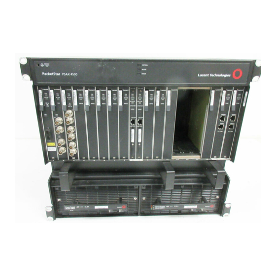
- Page 49 Chapter 1 Getting Started Comments on This Guide PSAX 4500 Multiservice Media Gateway The PacketStar PSAX 4500 Multiservice Media Gateway provides carrier-class reliability, with an unmatched range of service capabilities, end-to-end traffic prioritization, “any-service, any-channel” flexibility, and breakthrough voice technology. Ideal for the central office or a large enterprise multiservice media gateway, the PSAX 4500 system provides highly reliable network access for time-division multiplex voice, frame relay, 10/100BASE-T Ether- net, and ATM data applications.
- Page 50 Chapter 1 Getting Started Comments on This Guide ® PSAX Multiservice Media Gateway User Guide, Issue 1 Release 10.0.0 PacketStar 1-10 255-700-686R10.0.0...
-
Page 51: Psax 1000 Multiservice Media Gateway
(OC-3c/STM-1) access for an ATM edge switch; CDMA soft hand- off; and connection to SONET/SDH ready ATM network elements (for exam- ple, large routers). The PSAX 1000 system focuses on providing a highly reli- able carrier-class, multiservice access switch that can be deployed at the ATM network edge to carry voice, data, and video. - Page 52 Figure 2-1. PSAX 1000 Multiservice Media Gateway Chassis Hardware The PSAX 1000 chassis is 48.26-cm (19-in.) wide by 8.9 cm (3.5 in.) high by 36.8 cm (14.5 in.) deep and can be rack- or wall-mounted with the appropri- ate mounting brackets. It is designed to support two CPU3 modules, two Stratum 3–4/Power Supply modules (24 or -48 V dc or 110/220 V ac), and...
-
Page 53: Front View Of The Psax 1000 Chassis
Slot 15 Slot 16 Fan/Alarm Module Figure 2-2. Front View of the PSAX 1000 Chassis The rear panel has two slots for line interface modules (for future enhance- ments) and two slots for the Stratum 3–4/Power Supply modules (see Figure 2-3). It also includes two 24 or -48 V dc power connections for the Stratum 3–4/24 V dc Power Supply or Stratum 3–4/-48 V dc Power Supply... -
Page 54: Psax 1000 Chassis Hardware Specifications
(see the ® PacketStar PSAX 1000 Multiservice Media Gateway Installation Guide for details). Chassis Specifications The chassis specifications for the PSAX 1000 chassis are given in Table 2-1. Table 2-1. PSAX 1000 Chassis Hardware Specifications Specification Description Front panel slot configuration... -
Page 55: Psax 1250 Multiservice Media Gateway
Chapter 2 Hardware Description PSAX 1250 Multiservice Media Gateway System Environmental Specifications The environmental specifications for the PSAX 1000 system are described in Table 2-2. Table 2-2. PSAX 1000 System Environmental Specifications Parameter Value For AC-powered PSAX 1000 systems: Operating temperature range 0°... -
Page 56: Psax 1250 Multiservice Media Gateway(19-In.)
Chapter 2 Hardware Description PSAX 1250 Multiservice Media Gateway ~ Power Supply modules: 110 V ac, 220 V ac, or -48 V dc—two each for redundant operation For AC Power Supply modules, agency-approved AC power cordsets must be ordered separately with the chassis. ~ Stratum 3–4 module—two each for redundant operation FAIL FAIL... - Page 57 Two are required for active/standby operation. (see your Lucent Tech- nologies account manager for ordering information) • Input/output (I/O) and server modules (see your Lucent Technologies account manager for ordering information). • Blank faceplate modules—required for empty I/O and server slots Chassis Hardware The PSAX 1250 system can support either one or two Stratum 3–4 modules,...
-
Page 58: Psax 1250 48.26-Cm (19-In.) Chassis Backplane
Chapter 2 Hardware Description PSAX 1250 Multiservice Media Gateway If redundant Stratum 3–4 and Power supply modules are not used, the slots designated for these modules must remain empty. Blank faceplates are required in all empty slots. Backplane The chassis backplane distributes data, clock signals, and power to the mod- ules. -
Page 59: Psax 1250 58.42-Cm (23-In.) Chassis Backplane
Chapter 2 Hardware Description PSAX 1250 Multiservice Media Gateway Figure 2-7. PSAX 1250 58.42-cm (23-in.) Chassis Backplane Chassis Specifications The specifications for the PSAX 1250 chassis are given in Table 2-3. Table 2-3. PSAX 1250 Chassis Hardware Specifications Specification Description Slot configuration 16 slots total—12 slots for CPUn modules and 48.26-cm (19-in.) chassis:... -
Page 60: Psax 1250 System Environmental Specifications
Chapter 2 Hardware Description PSAX 2300 Multiservice Media Gateway System Environmental Specifications The environmental specifications for the PSAX 1250 system are described in Table 2-2. Table 2-4. PSAX 1250 System Environmental Specifications Parameter Value 0° to 50° C (32° to 122° F) Operating temperature range 5% to 85% relative humidity Operating humidity range... -
Page 61: Packetstar Psax 2300 Multiservice Media Gateway
• Central processing unit (CPUn (n=2 or 4)) module with the appropriately installed system software release (see your Lucent Technologies account manager for ordering information) • Input/output (I/O) and server modules (see your Lucent Technologies account manager for ordering information). • Blank faceplate modules—required for empty I/O and server slots... - Page 62 Chapter 2 Hardware Description PSAX 2300 Multiservice Media Gateway Chassis Hardware The PSAX 2300 chassis is a dc-powered, fully redundant 19- or 23-inch rack- mountable chassis. The physical dimensions are 17.5 inches wide, 15.75 inches high, and 12 inches deep. Cable management clips add another 1.5 in. to the front front of the chassis.
-
Page 63: Psax 2300 Chassis Hardware Specifications
Chapter 2 Hardware Description PSAX 2300 Multiservice Media Gateway 3.9 Gbps total bandwidth and allows live (power supplied) insertion of pri- mary and redundant common equipment modules, and input/output and server modules. Chassis Specifications The chassis specifications for the PSAX 2300 chassis are given in Table 2-5. Table 2-5. - Page 64 Chapter 2 Hardware Description PSAX 4500 Multiservice Media Gateway PSAX 4500 Multiservice Media Gateway System Features The PacketStar PSAX 4500 Multiservice Media Gateway provides carrier-class reliability, with an unmatched range of service capabilities, end-to-end traffic prioritization, “any-service, any-channel” flexibility, and breakthrough voice technology.
-
Page 65: Packetstar Psax 4500 Multiservice Media Gateway
• Central processing unit (CPUn (n=2 or 4)) module with the appropriately installed system software release (see your Lucent Technologies account manager for ordering information) • Input/output (I/O) and server modules (see your Lucent Technologies account manager for ordering information). • Blank faceplates are required for empty I/O and server slots Figure 2-9. - Page 66 Chapter 2 Hardware Description PSAX 4500 Multiservice Media Gateway The chassis includes 17 front-panel slots for input/output (I/O) and server modules for customer traffic, redundant stratum system timing, and central processing units for control and configuration. Two -48 V dc Power Supply modules reside below the cable turndown loops and air filter compartment in the middle of the chassis.
-
Page 67: Data Flow Through The Psax 4500 Midplane
Chapter 2 Hardware Description PSAX 4500 Multiservice Media Gateway The maximum bus capacity of the system can be 9.6 Gbps in a nonredundant system configuration. When a nonprotected system is configured, both Stra- tum modules would be required to carry 4.8 Gbps each with each bus run- ning at 1.2 Gbps. - Page 68 PSAX 1000 Stratum 3–4/Power Supply Modules The PSAX 1000 Stratum 3–4/Power Supply modules includes a power supply component for power conversion and distribution, a timing control compo- nent for system synchronization, and a sensor for system temperature con- trol.
-
Page 69: Psax 1000 Stratum 3-4/-48 V Dc Power Supply Module
For nonredundant operation, the Stratum 3–4/Power Supply modules must be installed in the slot labeled STRATUM SLOT 21/POWER SUPPLY SLOT 23 the PSAX 1000 Stratum 3–4/Power Supply module blank faceplate must be installed in the slot labeled STRATUM SLOT 22/POWER SUPPLY SLOT 24 In the console Equipment Configuration window, the module is displayed as two modules (slots 21 and 22 for the Stratum 3–4 component and slots 23... -
Page 70: Psax 1000 Stratum 3-4/110/220 V Ac Power Supply Module
If you do not have the appropriate cordset, contact your Lucent Technologies account manager. Figure 2-12. PSAX 1000 Stratum 3–4/110/220 V ac Power Supply Module 24 V dc Power Supply The module (see Figure 2-13) converts 24 V dc power to voltages required by... -
Page 71: Stratum 3-4/24 V Dc Power Supply Module
Chapter 2 Hardware Description Common Equipment Modules completely (when appropriate, separate independent power sources (com- mercial and backup power) of the same voltage should be used in redundant power applications). Figure 2-13. Stratum 3–4/24 V dc Power Supply Module Chassis Throughput Each Stratum 3–4 component supports a single bus and furnishes 600 Mbps of ATM bandwidth. - Page 72 Chapter 2 Hardware Description Common Equipment Modules The module accepts the following external timing sources: • Composite clock meeting ANSI T1.101 and ITU-T G.703 standards • BITS clock meeting Bellcore GR-518-CORE (DS1) and ITU-T G.812 (E1) standards The module provides the following timing modes: ANSI or ITU composite clock (64 kHz), T1BITS (1.55 MHz) or E1ETSI (2.048 MHz) external timing, line timing, and Stratum 3 internal freerun timing.
- Page 73 PSAX 1000 Fan/Alarm module temperature sensor to maintain a consistent temperature inside the chassis. Refer to “PSAX Alarm Modules” on page 2-41 for additional information on how the PSAX 1000 Fan/Alarm module and the PSAX 1000 Stratum 3–4/Power Supply module regulate the chassis temperature.
-
Page 74: Psax 1000 Stratum 3-4/Power Supply Module Specifications
Trap messages can be viewed on the Trap Log Dis- play window of the console interface or the AQueView window. PSAX 1000 The PSAX 1000 Stratum 3–4/Power Supply module specifications are given Stratum 3–4/Power in Table 2-9. - Page 75 Chapter 2 Hardware Description Common Equipment Modules Table 2-9. PSAX 1000 Stratum 3–4/Power Supply Module Specifications (Continued) Specification Description 110/220 V ac Power Supply Component Information Power • 100–127 or 200–240 V ac (autosensing) Input voltage range: • 2.5 A (100–127 V ac) or 1.5 A (200–240 V ac)
-
Page 76: Psax 1250 110 Vac, 220 Vac, And -48 V Dc Power Supply Modules
Chapter 2 Hardware Description Common Equipment Modules Three LED indicators on the faceplate provide status indications of the mod- ® ule. Refer to the PacketStar PSAX 1250 Multiservice Media Gateway Installation Guide for additional information. Figure 2-14. PSAX 1250 110 Vac, 220 Vac, and -48 V dc Power Supply Modules PSAX 1250 -48 V dc The specifications for the PSAX 1250 -48 V dc Power Supply module are Power Supply... - Page 77 Chapter 2 Hardware Description Common Equipment Modules PSAX 1250 110 V ac The specifications for the PSAX 1250 110 V ac Power Supply module are Power Supply found in Table 2-11. Module Specifications Table 2-11. 110 V ac Power Supply Module Specifications Specification Description Slot configuration...
-
Page 78: Psax 2300/4500 -48 V Dc Power Supply Module
Chapter 2 Hardware Description Common Equipment Modules PSAX 2300/PSAX 4500 Power Supply Module Functional Desciption Two -48 V dc Power Supply modules (see Figure 2-15) converts -48 V dc power to voltages required by the chassis for normal operation and distrib- utes power through the midplane to all of the modules in the chassis. -
Page 79: Functional Description
Chapter 2 Hardware Description Common Equipment Modules PSAX 2300/4500 The specifications for the PSAX 2300/4500 -48 V dc Power Supply module -48 V dc Power are given in Table 2-13. Supply Module Specifications Table 2-13. -48 V dc Power Supply Module Specifications Specification Description Slot Configuration... -
Page 80: Psax 1250 Stratum 3-4 Module
Chapter 2 Hardware Description Common Equipment Modules The Stratum 3–4 module is ITU-compliant and ANSI-compliant. The Stratum 3–4 module provide synchronization and common equipment monitoring for the PSAX 1250 system. Each Stratum 3–4 module supports a single bus and furnishes 600 Mbps of ATM bandwidth. Although the system can oper- ate with one Stratum 3–4 module, two (in slots 21 and 22) yield the maxi- mum system throughput of 1.2 Gbps and offer redundancy to protect service in case one module fails. -
Page 81: Stratum 3-4 Module Specifications
Chapter 2 Hardware Description Common Equipment Modules Table 2-14. Stratum 3–4 Module Specifications (Continued) Specification Description Synchronization source Line, internal, or external Accuracy Stratum 3 or 4, selectable External clock input ANSI/ITU-T Composite (64 kHz), T1BITS (1.544 MHz), E1ETSI (2.048 MHz), and DS0A Composite (64 kHz). Connector One RJ-12 (with either 120 ohm or 75 ohm termination) PSAX 2300 Stratum 3–4 Module... -
Page 82: Psax 2300 Stratum 3-4 Module Specifications
Chapter 2 Hardware Description Common Equipment Modules Table 2-15. PSAX 2300 Stratum 3–4 Module Specifications Specification Description Slot configuration Front two middle slots labeled Dimensions 15.8 cm H x 1.6 cm W x 24.1 cm D (6.2 in. H x 0.6 in. W x 9.5 in. D) Weight 0.22 kg (0.5 lb) Units per system... -
Page 83: Psax 4500 Stratum 3-4 Module
Chapter 2 Hardware Description Common Equipment Modules Figure 2-17. PSAX 4500 Stratum 3–4 Module Timing Control The module provides the following timing modes: ANSI or ITU composite clock (64 kHz), T1BITS (1.55 MHz) or E1ETSI (2.048 MHz) external timing, line timing, and Stratum 3+ internal freerun timing. With the ability to accept a timing reference from a variety of interfaces at low transmission rates, the system provides the network with a reliable transport and access infrastructure. - Page 84 Chapter 2 Hardware Description Common Equipment Modules • BITS clock meeting Bellcore GR-518-CORE (DS1) and ITU-T G.812 (E1) standards The module provides the following timing modes: ANSI or ITU composite clock (64 kHz), T1BITS (1.55 MHz) or E1ETSI (2.048 MHz) external timing, line timing, and Stratum 3 internal freerun timing.
- Page 85 Chapter 2 Hardware Description Common Equipment Modules 23N25 DSP2F Voice Server 23N41 Enhanced Router 20N40 Ethernet 20N41 Route Server 23N28 Tones and Announcements Server Two Stratum 3–4 modules are supported as two independent synchroniza- tion sources in a redundant configuration. Each module operates indepen- dently such that any one module can provide the system timing in the event the other one malfunctions or is removed.
- Page 86 Chapter 2 Hardware Description Common Equipment Modules ~ Failure of both Stratum modules ~ Failure of both fans (exception - system shutdown) The following information is reported through the console, Telnet, or EMS: • Stratum Mode (normal, holdover, or internal freerun timing) •...
-
Page 87: Stratum 3-4 Module Traffic Switcher
Chapter 2 Hardware Description Common Equipment Modules Slots 9-12 Stratum Module A Slots 1-4 Segment 1 Segment 3 600 Mbps 600 Mbps Single ATM Bus Single ATM Scalable to Bus Scalable to 1.2 Gbps 1.2 Gbps Slots 13-17 Bidirectional 325 Mbs Bidirectional 325 Mbs Slots 5-8 Segment 2... - Page 88 Description (see Figure 2-20) provides the processing, switching, and storage functions for the PSAX 1000 system. With a RISC-based microprocessor, the module has the processing power to maintain data flow, perform numerical calcula- tions, and manage PSAX 1000 provisioning functions. The module has a...
-
Page 89: Psax 1000 Cpu3 Module
Common Equipment Modules Figure 2-19. PSAX 1000 CPU3 Module PSAX 1000 CPU3 The specifications for the CPU3 module are given in Table 2-16. Module Specifications Table 2-16. PSAX 1000 CPU3 Module Specifications Specification Description Slot configuration Slot 16. For nonredundant operation:... - Page 90 Chapter 2 Hardware Description Common Equipment Modules PSAX CPU4 Module Functional Operating in a non-load sharing, primary/standby mode, the CPU4 module Description (see Figure 2-20) provides the processing, switching, and storage functions for the PSAX systems. With a RISC-based microprocessor, the module has the processing power to maintain data flow, perform numerical calculations, and manage PSAX system provisioning functions.
-
Page 91: Psax Cpu4 Module
The following PSAX Alarm modules are available for the PSAX systems as indicated: • PSAX 1000 Fan/Alarm module is used in the PSAX 1000 chassis only • Alarm module is used in the PSAX 1250, PSAX 2300, and PSAX 4500 chas- •... -
Page 92: Psax 1000 Fan/Alarm Module
Unless otherwise indicated, the PSAX Alarm modules function as follows: Description The PSAX 1000 Fan/Alarm module (see Figure 2-21) provides forced-air cooling, air filtration, external dry relay contact monitoring sensors, visible and audible CO alarm activation, and operational and alarm status indica- tions for the PSAX 1000 chassis. -
Page 93: Psax 4500 Alarm Module
Chapter 2 Hardware Description Common Equipment Modules ALARM CRITICAL MAJOR MINOR Figure 2-22. PSAX 4500 Alarm Module Critical Major Minor ALARM CRITICAL CO Alarms MAJOR MINOR Alarms Output Temp. Sensor Input Cold Figure 2-23. Example Configuration with the PSAX 4500 Alarm Module The PSAX 4500 Alarm module is functionally identical to the Alarm module (model 20N79), but the module is designed to be mounted only in the rear panel (slot... -
Page 94: Generating Central Office Alarms
Chapter 2 Hardware Description Common Equipment Modules Like all of the other PSAX modules, the PSAX 4500 Alarm module is moni- tored and controlled through the console or EMS-PSAX. For a detailed ® description of the PSAX 4500 Alarm module, see the PacketStar PSAX 4500 Alarm Module User Guide. -
Page 95: Alarm Outputs
Chapter 2 Hardware Description Common Equipment Modules MINOR ALARM CONNECTOR CRITICAL MAJOR Bell 3 Relays for Audible Alarms Critical Major Minor 3 Relays for Visible Alarms Critical Major Minor 1 Relay for Remote Alarm Cutoff Stratum module fails and a minor alarm command is sent to the Alarm Module. -
Page 96: Alarm And Psax 4500 Alarm Module Alarm Generation Criteria
Chapter 2 Hardware Description Common Equipment Modules Output Generation Criteria The generated Alarm and PSAX 4500 Alarm module alarms described in Table 2-18 occur under the following conditions: Table 2-18. Alarm and PSAX 4500 Alarm Module Alarm Generation Criteria This Alarm occurs… Under the following conditions… •... -
Page 97: Alarm Relay Operation
Chapter 2 Hardware Description Common Equipment Modules Table 2-19. Fan/Alarm Module Alarm Generation Criteria This Alarm occurs… Under the following conditions… • Loss of input power to the chassis—all module LEDs do not illuminate CRITICAL but a Critical alarm is generated when the alarm relay becomes unpow- ered and cause the relay contacts to change position •... -
Page 98: Alarm And Psax 4500 Alarm Module Alarm Connector Configuration
Chapter 2 Hardware Description Common Equipment Modules ALARM Connector 26-pin Audible Alarm Audible Alarm Critical Critical -OR- (Power Lost (Normally Energized Alarm Generated) No Alarm) Audible Alarm Major Audible Alarm Minor Visible Alarm Visible Alarm Critical Critical -OR- (Normally Energized (Power Lost No Alarm) Alarm Generated) -
Page 99: Fan/Alarm Module Alarm Connector Configuration
Chapter 2 Hardware Description Common Equipment Modules ALARM Connector 26-pin Audible Alarm Audible Alarm Critical Critical -OR- (Power Lost (Normally Energized Alarm Generated) No Alarm) Audible Alarm Major Audible Alarm Minor Visible Alarm Visible Alarm Critical Critical -OR- (Normally Energized (Power Lost No Alarm) Alarm Generated) -
Page 100: Audible Alarm Cutoff (Aco)
Chapter 2 Hardware Description Common Equipment Modules No Alarms PSAX Critical Major Minor Alarm Module Alarms Major Alarm Visible Alarm Panel Major Alarm Generated Major PSAX Critical Minor Alarm Module Alarms Major Alarm Generated Alarm Panel NO - Normally Open NC - Normally Closed COM - Common Figure 2-27. -
Page 101: Monitoring And Reporting On External Events
Chapter 2 Hardware Description Common Equipment Modules • Reports the change in state to the CPUn module The local and remote alarm cutoffs operate independently of each other. This change in state (on to off, off to on) is also shown in the Audible Alarm Sta- tus panel of the console Alarm Configuration window. -
Page 102: Control Outputs
Chapter 2 Hardware Description Common Equipment Modules Control Outputs The Alarm and PSAX 4500 Alarm modules can control up to four remotely controlled devices, such as air conditioning, heating, lighting, and so on, through four relays. The relays are controlled through the Control Outputs panel on the Alarm Module Configuration window. -
Page 103: Remote Status Inputs
Chapter 2 Hardware Description Common Equipment Modules PSAX Alarm Module AC Off Control Output 1 (AC Off) PSAX Alarm Module AC On Control Output 2 (AC On) Figure 2-30. Activating Supplemental Air Conditioning Remote Status Inputs For the Alarm and PSAX 4500 Alarm modules, fifteen remote status inputs are provided through the connector to enable remote sen- STATUS/CONTROL... -
Page 104: Optimizing I/O And Server Module Placement
Chapter 2 Hardware Description Optimizing I/O and Server Module Placement Optimizing I/O and Server Module Placement PSAX 1000 Chassis I/O and Server Unless otherwise described, the current PSAX I/O and server modules can be Modules installed in slots 1–4 in a redundant configuration, and slots 1–4 and 15 in a nonredundant configuration. -
Page 105: Module Performance And Power Consumption
Chapter 2 Hardware Description Module Performance and Power Consumption • The midplane contains two buses that control the flow of data between the module slots. Even numbered slots transmit on the B bus and odd num- bered slots transmit on A bus. For example, to prevent traffic congestion, install two 1-Port OC-12c/STM-4c (with AQueMan or Traffic Shaping) modules side-by-side in the same segment to maintain the 1.2 Gbps data flow on each bus in a nonprotected configuration. -
Page 106: Performance And Power Specifications For The Psax Modules
2 Divide MPCt by 0.85 to derive the total output power (Pt) consumed by the chassis, not to exceed 200 watts. The PSAX 1000 and PSAX 2300/4500 power supply modules are capable of handling any module configuration. Table 2-21. Performance and Power Specifications for the PSAX Modules... - Page 107 Chapter 2 Hardware Description Module Performance and Power Consumption Table 2-21. Performance and Power Specifications for the PSAX Modules (Continued) Total Module Maximum Maximum Output Chassis Module Amount of Program and Input Power ‡ § Buffer Speed † SDRAM Data Space Buffer Consumption DS3, E3, and STS-1e Interface Modules...
- Page 108 Chapter 2 Hardware Description Module Performance and Power Consumption Table 2-21. Performance and Power Specifications for the PSAX Modules (Continued) Total Module Maximum Maximum Output Chassis Module Amount of Program and Input Power ‡ § Buffer Speed † SDRAM Data Space Buffer Consumption 23N12...
- Page 109 Chapter 2 Hardware Description Module Performance and Power Consumption Table 2-21. Performance and Power Specifications for the PSAX Modules (Continued) Total Module Maximum Maximum Output Chassis Module Amount of Program and Input Power ‡ § Buffer Speed † SDRAM Data Space Buffer Consumption 20N63...
- Page 110 * The 6-Port Multiserial module can be installed in slots 1, 2, and 14 only of the PSAX 4500 chassis, and only in slot 1 of the PSAX 1000 chassis. On modules with PEC NS20N071DB and prior, port 5 of the module is not operational in the PSAX 1000.
- Page 111 Chapter 2 Hardware Description Module Performance and Power Consumption †† The SDRAM listed only takes into account the memory associated with the upper layer processor. It does not take into account the fastpath processor (firmware) or the hardware reassembly buffers. ®...
- Page 112 Chapter 2 Hardware Description Module Performance and Power Consumption ® PSAX Multiservice Media Gateway User Guide, Issue 1 Release 10.0.0 PacketStar 2-62 255-700-686R10.0.0...
-
Page 113: System Features
• An advanced queuing and cell-switching algorithm, provided by the AQue- Man (adaptive queue management) firmware algorithm, a patented tech- nology offered by Lucent Technologies to differentiate voice, video, and data requirements. The AQueMan algorithm maximizes bandwidth effi- ciency while ensuring QoS on a congested network. - Page 114 Chapter 3 System Features System Capabilities • A connection gateway application programming interface (CG API) that provides an interface to the PSAX system by which an external workstation (gateway) can control the PSAX system ATM switching, using non-native ATM networking protocols Through the use of the CG API, the gateway and the PSAX system can combine to perform powerful interworking among ATM, integrated ser- vices digital network (ISDN), signaling system 7 (SS7), channel associated...
-
Page 115: Interface Architecture
Chapter 3 System Features Interface Architecture Interface Architecture The PSAX system interface architecture distinctly separates the ATM adapta- tion functions from the switching functions of the PSAX system. The inter- face architecture provides for the following distinct processes: • Physical media access—The physical media access layer handles functions specific to each physical interface, connecting each user port to other users or network elements. -
Page 116: Spvc Reconnection Priority Scheme
Chapter 3 System Features Connections Supported figured, an SPVC can be established between the two network interfaces serving the PVC by using signaling procedures. Consequently, this type of connection has attributes of both an SVC and a PVC. Specifically, an SPVC is established and released between the two network interfaces serving the PVC. -
Page 117: Sample Spvc Reconnection Prioritization Scheme
Chapter 3 System Features Connections Supported Table 3-1. Sample User-Defined Priority Scheme for Reconnecting SPVC ATM IMA Links User-Assigned Traffic Type Typical ATM Service Type Priority Code TDMA/CDMA control channels or CBR-1 or VBR-express or AMPS channel reserved for 911 CBR-2 emergency calls GSM control channels... -
Page 118: Modification Of Parameters For Active Spvc Connections
Chapter 3 System Features Connections Supported • The maximum total number of AAL2 SPVC trunk connections in the chas- sis must not exceed 32. • The ATM uplink must be a 6-Port DS1 IMA module. • The PSAX system with the priority system enabled will work with a PSAX system with passive side SPVCs that has the priority system disabled. -
Page 119: Svc Functional Description
Chapter 3 System Features Connections Supported • SVCs can be allocated on UNI (public and private), IISP, and PNNI inter- faces. • Point-to-point and point-to-multipoint VCC connections are supported. • VCC connections support both symmetric and asymmetric bandwidth requirements. • Process 60 calls per second. Maximum limits include 100 UNIs per system; 5,000 simultaneous point-to-point SVC call originations, and 2,000 point- to-multipoint call originations. -
Page 120: Svc Call State Transition Messages
Chapter 3 System Features Connections Supported Table 3-2. SVC Call State Transition Messages Call States Description #0—Null No call exists. • User—The user has requested that the system establish an outgo- #1—Call initiated ing call on the network. • Network—The network has received the call establishment request, but has not yet responded to the outgoing call. -
Page 121: User Interfaces
Chapter 3 System Features User Interfaces Call establishment messages: • Call proceeding • Connect • Connect acknowledgment • Setup Call clearing messages: • Release • Release complete • Status Miscellaneous messages: • Status inquiry The information elements used in the Call Establishment-Setup message allow the user to request the called party number, specific PCR, SCR, MBS, QoS class, forward and backward direction rates, performance, congestion control parameters, and so on, from the PSAX system UNI. -
Page 122: Circuit Emulation Service
Chapter 3 System Features User Interfaces Circuit Emulation Service Circuit emulation service transports traffic over a virtual channel-based con- nection, providing service to the end user that is indistinguishable from a real point-to-point, fixed-bandwidth circuit. The PSAX system supports struc- tured circuit emulation (individual DS0 circuit emulation) of traditional voice-based and data services on the DS1 and E1 modules. -
Page 123: Dynamic Cac
Chapter 3 System Features User Interfaces ATM Forum Specification af-vtoa-0085.000. Note that this feature is not fully compliant with the specification and does not interoperate with other devices that are fully compliant. The DBCES feature, in essence, performs idle channel suppression for voice traffic. -
Page 124: Hdlc Passthrough Bit Inversion
Chapter 3 System Features User Interfaces HDLC Passthrough Bit Inversion The High-level data link control (HDLC) Passthrough Bit Inversion feature uses an ITU-TSS link layer protocol standard for point-to-point and point-to- multipoint communication. To reduce framing errors, control information is always placed in the same position in the traffic stream, and the control bit pattern is different from the data bit pattern. -
Page 125: Pnni Features Supported By The Psax Systems
Chapter 3 System Features User Interfaces PNNI provides a method for signaling used to establish point-to-point and point-to-multipoint connections across ATM networks. PNNI is based on the ATM Forum UNI signaling, with mechanisms added to support source rout- ing, crankback and alternate routing of all call setup requests in case of con- nection setup failure. -
Page 126: Pnni Peer Group Dynamics
Chapter 3 System Features User Interfaces • Source path selection and generic connection admission control (GCAC) PNNI Peer Group PNNI performs these functions: Dynamics • Simplifies the configuration of large networks because it allows ATM switches to automatically learn about their neighbors and to distribute call routing information dynamically. -
Page 127: Pnni Hierarchies
Chapter 3 System Features User Interfaces PNNI Hierarchies A topology showing three hierarchal node levels (grandparent, parent, and child peer groups), peer group leader nodes, and peer group member nodes is shown in Figure 3-2. Each node, at any level, has its address and rank on the network described on the PNNI Node Configuration window. -
Page 128: Atm Maintenance
Chapter 3 System Features User Interfaces Grandparent Peer Group Logical Link Logical Group Node Highest Level Peer Group Peer Group Leaders Parent Peer Group PG (A) PG (B) Child Peer Groups PG(A.2) A.2.3 PG(B.1) PG(B.2) A.2.2 PG(A.1) PG(C) B.2.1 A.2.1 B.1.1 PG(A.4) B.2.2... -
Page 129: Path And Connection Trace
Chapter 3 System Features User Interfaces away from the PNNI link with the high administrative weight, sending it to the preferred connection with lower administrative weight. The freed-up interface can then be reconfigured. ATM Maintenance Mode is a way of rerouting SPVCs and SVCs from an ATM port running PNNI. -
Page 130: Ilmi Over Pnni Overview
Chapter 3 System Features User Interfaces Based on an ATM Forum-defined interim specification, ILMI uses a limited subset of Simple Network Management Protocol (SNMP) capabilities. ILMI provides status information and statistics using SNMP and a MIB to provide any ATM device with status and configuration information about the follow- ing information available at its ATM interfaces: •... -
Page 131: Atm Uni 4.0 Signaling
Chapter 3 System Features User Interfaces printed circuit boards into the motherboard of the emulating device, and/or special software. The 6-Port Multiserial module is the only PSAX I/O module that supports this interface. ATM UNI 4.0 Signaling The ATM UNI 4.0 Signaling feature supports the mandatory functions required by the ATM Forum UNI Signaling Specification Version 4.0, as well as some of its optional features. - Page 132 IMA ID is used to identify a group to the far-end, pick a unique value instead of leaving it as the default of 0. The PSAX 1000 and the PSAX 4500 systems provide efficient transport of traffic transport between cell sites and the mobile switching centers (MSCs).
-
Page 133: Frame Relay-To-Atm Interworking
Chapter 3 System Features User Interfaces 23N68 1-Port DS3 IMA 23N75 1-Port Channelized OC-3/STM-1 Unstructured CES/ATM Multimode (STM-1 ATM operating mode) 23N76 1-Port Channelized OC-3/STM-1 Unstructured CES/ATM Single-Mode (STM-1 ATM operating mode) 20N33 6-Port DS1 IMA 20N34 6-Port E1 IMA 23N33 12-Port Medium-Density DS1 IMA 23N34... -
Page 134: Frame Relay-To-Frame Relay Interworking
Lucent Stinger DSLAM, CellPipe/Verilink IAD, or AdTran IAD, and a cen- tral office voice switch, such as the Lucent Technologies 5ESS switch, or with a Nortel DMS switch. Operating on T1 circuits, the GR-303 digital loop carrier service has provi- sions for both an open interface network architecture and a digital loop car- rier system. -
Page 135: Fax/Modem Master/Slave Support
Chapter 3 System Features User Interfaces The PSAX system also supports these features: • Caller ID • Call forwarding • Call transfer • Call waiting • Cancel call waiting • Customer callback • Speed dialing • Three-way calling • Loop start •... -
Page 136: Idle Channel Suppression Support For The Cellpipe Iad
Chapter 3 System Features Dynamic Bandwidth Allocation Idle Channel The CellPipe IAD is certified to not transmit silence cells between itself and Suppression Support the PSAX system when in the on-hook state if a channel is idle (supporting for the CellPipe IAD no active connection). -
Page 137: Dba-Controlled Backplane Traffic
Chapter 3 System Features Dynamic Bandwidth Allocation transmission of cells (CBR traffic) from the CE side of the connection, the PSAX system saves bandwidth that can used for other types of traffic on the connected ATM trunk. When incoming traffic from the backplane towards the CE side of a CE-to-ATM connection is 50 percent or more of the configured interface (strapped) bandwidth, cells are being transmitted from the CE side to the backplane. -
Page 138: Network Management
Chapter 3 System Features Network Management The DBA feature is supported on the following module: 24N64 12-Port Medium-Density DS1/E1/DS0A CES (DS1 mode only) Network Management The PSAX system provides all the telecommunications management network (TMN) functions applicable to the system. The PSAX system (which contains network elements) can be managed in several ways using a network element management system or network management system. -
Page 139: Simple Network Management Protocol Version 3
Chapter 3 System Features Network Management sion is used to manage a PSAX system, then the console interface is dis- played (similar to that which is used for the serial interface, as explained above). Only one person can have access to the console interface at a time; therefore, direct access using the serial port precludes telnet access using the Ethernet port. -
Page 140: Navis Ems-Psax System
Element Management System) is a GUI-based element management tool that is used to provision the PacketStar PSAX 1000, PSAX 1250, PSAX 2300, and PSAX 4500 systems. The EMS-PSAX enables a network of PSAX devices to be managed and provisioned from a single location, using easy-to-use windows. -
Page 141: Psax System Software Features
Chapter 3 System Features PSAX System Software Features PSAX System Software Features Bulk Statistics Collection The Bulk Statistics feature provides the ability to send collected interface and connection statistics to a remote statistics server, such as the NavisXtend Sta- tistics Server. The collection of PSAX system statistics can be used for net- work management/reporting such as historical trend analysis, network design and planning, and customer network management (CNM)-based reports. -
Page 142: Psax System As A Tcp Client/Server For The Connection Gateway Api
Chapter 3 System Features PSAX System Software Features For channel-associated signaling (CAS), the Connection Gateway API offers both R1 and R2 support. The gateway supports switched voice traffic over ATM by improving narrowband options through AAL1 and AAL2 trunking. The gateway provides service level interworking, provisioning, fault monitor- ing, continuity service checking, and line testing support for the Channelized DS3 module and/or the STS-1e T1 module. -
Page 143: Fractional Pri Support
Chapter 3 System Features PSAX System Software Features You can also set up the PSAX system as a TCP server device with the call con- troller set up as the client device. As an option, you can connect two call con- trollers, set up as primary and backup client devices, to the PSAX system (server device) (see Figure 3-5). -
Page 144: Ds1 Ani In-Line Codes For Loopbacks
Chapter 3 System Features PSAX System Software Features The PSAX system support for the PNNI protocol enhances the current ATM call control capability of CGs to be able to dynamically setup and release ATM connections through egress/ingress ports of PNNI interfaces connecting to the PNNI network. -
Page 145: Psax System Traffic Protection Capabilities
• “N:1 Traffic Protection with the PSAX 4500 System” • “1:1 Traffic Protection with the PSAX 1000 System” on page 3-37 • “1:1 Traffic Protection with the PSAX 24-Port RJ Protection Patch Panel” on page 3-40 •... - Page 146 Chapter 3 System Features PSAX System Software Features installed at the rear of the chassis, receive incoming traffic and transmit out- going traffic via the attached network cables on the external connectors on the faceplates. The LIM3–4 modules are electrically connected to the protec- tion module for a protection group via the midplane.
- Page 147 Chapter 3 System Features PSAX System Software Features • Manual switchover initiated by the user • Nonservice affecting upgrades The protection module monitors the operation of the working module. Inter- Slot Communication (ISC) cells are exchanged between the working and protection module.
-
Page 148: N:1 Traffic Protection Scheme On The Psax 4500 System
Chapter 3 System Features PSAX System Software Features Figure 3-6 illustrates the data flow in an N:1 scheme during normal opera- tion, and the data flow while the protection modules are in Active mode fol- lowing the failure of a working module in groups 1 and 2. LIM3-4 LIM3-4 LIM3-4... -
Page 149: 1:1 Traffic Protection With The Psax 1000 System
LIMn module. 1:1 Traffic Protection The PSAX 1000 system is designed to provide 1:1 traffic protection for the with the PSAX 1000 PSAX product line as described in this section. - Page 150 Chapter 3 System Features PSAX System Software Features In the 1:1 scheme, one working module in a protection group is associated with one protection module. Under normal conditions, the working module in a protection group is in Active mode, exchanging traffic, and the protec- tion module is in Standby mode.
-
Page 151: 1:1 Protection Scheme On The Psax 1000 System
FAILED ACTIVE Failed Working Module Figure 3-7. 1:1 Protection Scheme on the PSAX 1000 System Restoration of Service on the Working Module After automatic or manual switchover has been performed and the replace- ment or testing of the working module is completed, the user manually switches the traffic back from the protection module to the working module, ®... -
Page 152: 1:1 Traffic Protection With The Psax 24-Port Rj Protection Patch Panel
Chapter 3 System Features PSAX System Software Features which resumes Active mode. The following events occur depending on whether the working module is an existing one having all configurations loaded, or is a new module that replaces a failed working module. •... - Page 153 Chapter 3 System Features PSAX System Software Features this condition is that processing on the working module is interrupted or sus- pended. Other causes of this condition are the removal of the working mod- ule from the chassis or a failure of the module. Switchover Events During the switchover of traffic from the working module to the protection module, various events occur depending on the reason why the switchover...
-
Page 154: 1:1 Protection Scheme On The Psax System
Chapter 3 System Features PSAX System Software Features Chassis Backplane Backplane Working Protection Active Standby Module Module Slot 3 Slot 4 Protection Patch Panel Line Normal Data Flow Chassis Backplane Backplane Working Protection Failed Active Module Module Slot 3 Slot 4 Protection Patch Panel Line Failed Working Module... -
Page 155: Aps/Msp Protection On The Optical Modules
Chapter 3 System Features PSAX System Software Features When the user inserts the new replacement module into the chassis, the PSAX system recognizes it as an unconfigured module. The user then exe- cutes the switchover command and the PSAX 24-Port RJ Protection Patch Panel switches control from the protection module running in Active mode to the working module. -
Page 156: Interface Protection Group With Atm Interfaces
Chapter 3 System Features PSAX System Software Features 20N93 1-Port STM-1 1+1 MSP Single-Mode 23N12 1-Port Channelized OC-3/STM-1 CES Multimode 23N13 1-Port Channelized OC-3/STM-1 CES Single-mode 23N34 21-Port High-Density E1 IMA 23N72 1-Port OC-12c/STM-4c Multimode 23N73 1-Port OC-12c/STM-4c Single-Mode 23N74 3-Port DS3/E3 ATM (E3 mode) 23N75... -
Page 157: Typical Interface Protection Group Configuration
Chapter 3 System Features PSAX System Software Features 1. Configure the module ports, channels, and interfaces (physical layer interface) 2. Configure the connections (ATM layer and IWF) 3. Configure the interface protection groups Figure 3-9 illustrates how a typical interface protection group configuration works. -
Page 158: Alternate Rerouting Using Dhpvc
Chapter 3 System Features PSAX System Software Features Alternate Rerouting To protect ATM traffic from network outages, the PSAX system can detect Using DHPVC alarms or failures on an ATM backbone and reroute PVC traffic around the affected portions of the network. Using dual-homed permanent virtual cir- cuits (DHPVCs), the PSAX system performs the rerouting function automati- cally, without relying on operator intervention or rerouting capabilities within the network itself. -
Page 159: Firmware Release Control
Chapter 3 System Features PSAX System Software Features Debouncing Period field on the Site-Specific Configuration window, the user can select a value from the range 1 to 300 seconds (1,000–300,000 msec). The value the user sets in this field specifies the length of time that must elapse since receiving any AIS/RDI alarm on a primary PVC connection before the PSAX system automatically switches the traffic from the standby (backup) connection back to the primary connection. -
Page 160: Forward Error Correction
Chapter 3 System Features PSAX System Software Features You do not need to download an I/O or server module’s firmware separately from the PSAX system software upgrade. When the PSAX system software is upgraded using the SRD Download Configuration window (see Chapter 13), the system reboots and all firmware of the I/O and server modules (in the rebooted chassis) is also upgraded. -
Page 161: Forward Error Correction Automatic Rate Options
Chapter 3 System Features PSAX System Software Features encoded data, now approximately 48 bytes larger, is loaded into new cell payloads and forwarded to the 6-Port Multiserial module or a Quadserial module for transmission. The user selects a Reed Solomon encoding rate with a specific error-correc- tion capability, as follows: •... -
Page 162: H.248 Media Gateway Access Protocol
Chapter 3 System Features PSAX System Software Features H.248 Media Gateway Access Protocol The PSAX systems support the ITU-T Recommendation H.248.1 (03/2002). This communication control protocol for convergent networks separates call control and media- and bearer-control functions. After the call control and media- and-bearer control functions are separated, they are transmitted over different network elements. - Page 163 Chapter 3 System Features PSAX System Software Features interfaces in the PSAX system can be viewed on the Interface Name Table window, which is accessed from the Equipment Configuration window. The following interface types support interface naming: • ATM IISP user and network •...
-
Page 164: Internet Protocol (Ip) Throttling
Chapter 3 System Features PSAX System Software Features Internet Protocol (IP) Throttling The IP Throttling feature limits the rate at which the CPUn module accepts IP traffic (through the port or by the in-band management virtual ETHERNET port) to prevent the CPUn module from being excessively burdened with traffic. -
Page 165: Relationship Between Lanet And The Osi Model
Chapter 3 System Features PSAX System Software Features SERVICE-INDEPENDENT ARCHITECTURE Voice Video Images Data Layer 7 Layer 6 Layer 5 Layer 4 CELL-BY-CELL ENCRYPTION Layer 3 Layer 2 LANET Protocol Layer 1 Encryption Error Correction Bit Interleaf Satellite Radio Land Lines From bits per second to megabits per second Figure 3-11. -
Page 166: Operations, Administration, And Maintenance (Oam)
Chapter 3 System Features PSAX System Software Features encodes the header address within the same 10-nibble header space of stan- dard ATM cells. In addition, it avoids the extra delay (detrimental to CBR traffic) required of multiple header-encoding schemes. In practice, to tolerate 2-bit random errors or 5-bit burst errors requires set- ting up 526 addresses for each channel. -
Page 167: Oam Cell Characteristics
Chapter 3 System Features PSAX System Software Features OAM performs this function by injecting cells which contain OAM informa- tion into the network traffic. This information is referred to as a flow. In order for an OAM flow to function properly, there must be an exchange of opera- tional information between the various nodes in a network. -
Page 168: Oam Cell Fields
Chapter 3 System Features PSAX System Software Features Header Payload OAM Function Type Reserved Header 360 bits (45 bytes) Function-specific field Error Cell Detection Type Code Figure 3-13. OAM Cell Fields • Header: this is the same as the ATM cell header •... -
Page 169: Oam Atm Layer Flows
Chapter 3 System Features PSAX System Software Features 20N92 1-Port STM-1 1+1 MSP Multimode 20N93 1-Port STM-1 1+1 MSP Single-Mode 23N07 Quadserial 23N33 12-Port Medium-Density DS1 IMA 23N34 21-Port High-Density E1 IMA 23N35 24-Port High-Density DS1 Multiservice 23N60 1-Port Channelized DS3 Multiservice 23N62 1-Port Channelized STS-1e, T1 Format 23N64... -
Page 170: Oam F4 Flows
Chapter 3 System Features PSAX System Software Features Figure 3-14. OAM Hierarchy OAM F4 Flows OAM flows for F4 in-band maintenance are defined at the ATM layer for the VPC level. It is used for path level connections, where the VP flows are iden- tified by reserved values within the path. -
Page 171: Psax Modules Supporting Oam Flows
Chapter 3 System Features PSAX System Software Features • Existence in the same physical route for fault correlation and performance information User cells at the F5 level carry VCI cells which are defined as follows: • PTI=4 is a segment OAM F5 flow cell. This flow is identified by its standard- ized PTI, and is used for end-to-end VCC operations communication. -
Page 172: Atm Layer Oam Functions
Chapter 3 System Features PSAX System Software Features Table 3-4. Modules Supporting OAM Flows (Continued) OAM Flow Modules Fiber-Optic Interface Modules 20N72 1-Port OC-3c 1+1 APS Multimode 20N73 1-Port OC-3c 1+1 APS Single-Mode 20N92 1-Port STM-1 1+1 MSP Multimode 20N93 1-Port STM-1 1+1 MSP Single-Mode 23N12 1-Port Channelized OC-3/STM-1 CES Multimode... -
Page 173: Oam Activation/Deactivation Cells
Chapter 3 System Features PSAX System Software Features ~ Loopback — Loopback checks isolate failed entities if defect information is insufficient. A loopback check detects faults in the physical and ATM layers, and detects defects and declarations of failure within the network elements. -
Page 174: Packetpipe Aal5-To-Aal2 Wireless Trunking For Mobile Voice
Chapter 3 System Features PSAX System Software Features Both cells are neither A-B nor B-A cells, but are cells that move bidirec- tionally. Correlation tag cells give the number used to correlate transmitted activa- tion/deactivation requests with their responses PM block size (A-B, B-A) is a feature that works with activation requests only. -
Page 175: Traffic Management Using The Aqueman Algorithm
Chapter 3 System Features PSAX System Software Features The procedure to access the console interface Trap Log Display window and decriptions of the SNMP trap messages are provided in the document, ® PacketStar PSAX Simple Network Management Protocol (SNMP) Trap Reference Guide. -
Page 176: Atm Traffic Management
Chapter 3 System Features PSAX System Software Features ority VBR data in cases where there are too many cells in lower-priority VBR buffers and relatively few cells in higher-priority VBR buffers. The execution of this algorithm is based on the priority levels the user selects. •... -
Page 177: Usage Parameter Control
Chapter 3 System Features PSAX System Software Features 23N76 1-Port Channelized OC-3/STM-1 Unstructured CES/ATM Single-Mode 45N74 3-Port DS3/E3 ATM Protection Usage Parameter Usage parameter control (UPC) allows the end system to police ingress con- Control nections for service level agreement compliance. After a set of service catego- ries is specified, UPC is given a set of parameters for each, describing the traf- fic presented to the network and the quality of service the network requires. -
Page 178: Early Packet Discard
Chapter 3 System Features PSAX System Software Features Early Packet Discard The PSAX system ATM Traffic Management feature includes the implemen- tation of the EPD function for PVC and SPVC connections that support the service type UBR and the SAR type AAL5. The EPD function improves the efficiency of the connection by reducing the amount of bandwidth needed when traffic congestion occurs. -
Page 179: Configuring Atm Traffic Shaping
Chapter 3 System Features PSAX System Software Features 4-Port Ethernet Module Side A PSAX Chassis Backplane or A to B Side Ingress Midplane Tx/Rx Bursty PCR to 6 MB Egress B to A Side Traffic Shaping does not occur on egress B to A side direction 2-Port or 4-Port OC-3c/STM-1 Module Side B B to A Side... -
Page 180: Task Summary For Implementing Atm Traffic Shaping
Chapter 3 System Features PSAX System Software Features ATM traffic is subject to shaping on a per-connection basis and is available on the UBR, VBR, and GFR service types. The following PVC connections support traffic shaping: • AAL2 Trunk Connection (PVC only) •... -
Page 181: Atm Traffic Shaping For Cbr And Vbr-Rt
Chapter 3 System Features PSAX System Software Features interface increases, the probability increases that ATM traffic-shaped traffic will have to be queued. This will impede the ability to maintain the PCR of the ATM traffic-shaped connection(s) and eventually the queues will over- flow, causing packets to be dropped. -
Page 182: Atm Traffic Management Capabilities By Module
Chapter 3 System Features PSAX System Software Features Table 3-6. ATM Traffic Management Capabilities by Module Feature Support ATM Traffic Shaping (TS) Max. Precision for Modules Min. Queue EPD GFR UPC VI TS No. of Priority Size † Connection DS1/T1 Interface Modules 23N33 12-Port 2 ×... -
Page 183: Virtual Interfaces
Chapter 3 System Features PSAX System Software Features Table 3-6. ATM Traffic Management Capabilities by Module (Continued) Feature Support ATM Traffic Shaping (TS) Max. Precision for Modules Min. Queue EPD GFR UPC VI TS No. of Priority Size † Connection 2 ×... -
Page 184: Sample Uses Of Virtual Interfaces
Chapter 3 System Features PSAX System Software Features Single PVC VCC with UPC Single VPC w/ multiple SVC Virtual Interface 1 VPI/VCI inside Virtual Interface 2 Virtual Interface 3 Virtual Interface 4 Multiple VPC w/ UPC Virtual Interface 0 WAN ATM Link All other Traffic with UPC control and Traffic Shaping Figure 3-17. -
Page 185: Combining The Upc Feature And Either The Ts Or Vi Feature On A Connection
Chapter 3 System Features PSAX System Software Features Table 3-7. ATM Traffic Shaping, UPC Support, and VI Support Configuration Compatibility Fields on ATM UNI, PNNI, and IISP ATM Traffic VI Support UPC Support Configuration Windows Shaping per VC ATM Traffic Shaping per VC VI Support UPC Support * UPC support and Traffic Shaping per VC are supported on the same end-to-end... - Page 186 Chapter 3 System Features PSAX System Software Features V5.2 European IDLC Overview of the V5.2 The PSAX system implementation of the V5.2 IDLC application offers loop Application emulation services for PSTN and ISDN-PRI. The VoDSL oversubscription is done on the local exchange end of the connection. The configuration of the access network and the IAD supports the oversubscription.
- Page 187 Chapter 3 System Features Voice Processing CPUn module and the envelope function that creates the C-channel with D- channel information. The bearer channels will be directed to the DSP2G Voice Server module and processed according to decisions made by the CPUn module.
- Page 188 Chapter 3 System Features Voice Processing This feature supports packet-switched wireless backhaul networks for inter- connecting Lucent MSCs and Series II base stations using the Lucent propri- etary packet pipe protocol over land lines. This protocol performs encapsula- tion within ATM AAL2 for various cell site sizes. The DSP2E Voice Server module is a high-speed, multifunction digital signal processing module that performs conventional voice compression, as well as AAL5-to-AAL2 conversions.
-
Page 189: Packetpipe Aal5-To-Aal2 Wireless Trunking From Cell Site To Msc For Mobile Voice
Chapter 3 System Features Voice Processing PSAX 4500 in MSC PSAX 1000 Cell Sites Pure Voice HDLC AAL2 Trunks AAL5 Backhauled via Land Lines Cellular Data/Voice in Same Packet Data/AAL5 TDM Voice/AAL1 5ESS 168 Channels PacketPipe 48 Channels TDM/AAL2 Bit Inverted HDLC/AAL2... -
Page 190: Virtual Router Concept
Chapter 3 System Features Voice Processing IP interfaces (as well as the underlying IP traffic through each module) may have overlapping address space without the concern of crosstalk from one VPN to the next. Each Enterprise/Service Provider Enterprise 1/ Enterprise 2/ Enterprise 3/ occupies its own Service Provider 1... -
Page 191: Route Server And Example Configuration
Chapter 3 System Features Voice Processing Existing Console FR Connections Partitioned In-Band into IP Network Interfaces Management 192.001.001.001 255.255.255.000 Virtual 192.001.002.001 Router 255.255.255.000 192.001.003.001 255.255.255.000 145.121.215.001 Virtual 255.255.000.000 Router 145.122.215.001 Exisiting In Band Management 255.255.000.000 145.123.215.001 192.001.004.001 255.255.000.000 255.255.255.000 192.001.005.001 A network interface may be 255.255.255.000 assigned a VC that... -
Page 192: End-To-End Continuity Check
Chapter 3 System Features Voice Processing Secure Telephone Unit Third Generation (STU-III) Secure Mode STU-III support permits the DSP2D and DSP2E Voice Server modules to detect the transition of a voice call from 8 Kbps or 32 Kbps mode to a STU-III secure mode and to transmit the subsequent data stream in a compressed 32 Kbps rate. - Page 193 Chapter 3 System Features Voice Processing GSM Voice Traffic Compression The primary objective of GSM Idle Channel (No Speech Frame) Suppression and GSM Idle Speech Frame Suppression is to minimize the number of GSM voice traffic circuits between the cell sites (BTS) and the BSC. Suppressing the idle traffic will allow for greater trunk utilization and greater operational expense savings to wireless carriers.
-
Page 194: System
Chapter 3 System Features System Performance DSP resource pools are chassis-wide pools of DSP2G DSP channels. A single DSP pool may contain DSP resources from multiple DSP2G modules. A DSP Pool can be assigned to an ATM trunk or an AAL2 trunk with a trunk multi- plexing type of ATM. - Page 195 Chapter 3 System Features System Performance Non-Service-Affecting Firmware Upgrades The Non-Service-Affecting Upgrades feature provides the PSAX system the ability to upgrade new firmware drivers on the PSAX Traffic Protection mod- ules—which include LIM-protected modules, 1+1 APS/MSP-protected mod- ules, and Patch Panel-protected modules—without affecting the traffic flow. This feature is designed to automatically download new firmware drivers in a sequential fashion to Traffic Protection modules when they are configured in N:1 protection groups, 1:1 protection module pairs, and 1+1 APS/MSP pro-...
- Page 196 Chapter 3 System Features System Performance The Non-Service-Affecting Upgrade feature is supported on the following PSAX I/O and server modules: 45N74 3-Port DS3/E3 ATM Protection 45N03 3-Port Channelized DS3/STS-1e CES Protection 45N02 3-Port Unstructured DS3/E3 CES Protection 23N35 24-Port High-Density DS1 Multiservice 20N72 1-Port OC-3c 1+1 APS Multimode 20N73...
- Page 197 Chapter 3 System Features System Performance of the later software release from the new standby module to the primary module that has the older software release, the Primary Switchover command on the Remote Reboot Configuration window must be executed to make the primary CPUn module the standby CPUn module. Then the new Synchronize Standby CPU Software Version command can be executed on the primary CPUn module (with the later software release) to cause it to copy the later software release and configuration files to the...
-
Page 198: System Security
Chapter 3 System Features System Security • UserConfigured Byte (where =1, 2, 3, or 4) The BER testing can be run as a short-term test for troubleshooting the facil- ity or as a test running continuously for 24 to 48 hours. Reduction in Post-Dial Delay Event handling processes within the PSAX system are designed so that the amount of time needed to set up a call for an SVC connection is now 30 msec... -
Page 199: Psax System Access Authentication Via Radius Servers
ATM UNI 3.0, 3.1, and 4.0 and ATM PNNI 1.0 inter- faces. The ATM Security feature is available only to users in certain countries. Con- tact your Lucent Technologies sales representative to find out whether your country is eligible to use the ATM Security feature. ®... - Page 200 Chapter 3 System Features SDH Synchronization Status Messages (SSMs) SDH Synchronization Status Messages (SSMs) The Synchronous Digital Hierarchy (SDH) Synchronization Status Messages (SSMs) are identifiers that are embedded within the reference signals that are used as synchronization sources for Timing Signal Generators (TSGs) and other network elements (NEs).
- Page 201 Chapter 3 System Features PSAX Module Features PSAX Module Features For descriptions of the I/O and server modules available for use in the ® PacketStar PSAX Multiservice Media Gateways, see Appendix D. ® PSAX Multiservice Media Gateway User Guide, Issue 1 Release 10.0.0 PacketStar 255-700-686R10.0.0...
- Page 202 Chapter 3 System Features PSAX Module Features ® PSAX Multiservice Media Gateway User Guide, Issue 1 Release 10.0.0 PacketStar 3-90 255-700-686R10.0.0...
- Page 203 Using VT100 Terminal Emulation Overview of This Chapter The PSAX systems can be accessed through VT100 terminal emulation for local access or from a remote location using telnet sessions. This access is used in configuring, managing, and monitoring the PSAX systems. This chap- ter describes how to connect and configure a VT100-compatable terminal emulator to access the PSAX system.
-
Page 204: Connection Description Window
Chapter 4 Using VT100 Terminal Emulation Setting Up The Windows HyperTerminal Emulator Setting Up The Windows HyperTerminal Emulator To configure VT100 terminal emulation using a Windows HyperTerminal emulator, perform the following procedure. Begin 1 Do one of the following, depending on your operating system (see Table 4-1): Table 4-1. -
Page 205: Connect To Window
Chapter 4 Using VT100 Terminal Emulation Setting Up The Windows HyperTerminal Emulator The Connect To window is displayed (see Figure 4-2). Figure 4-2. Connect To Window 5 In the Connect using field, select COM1. 6 Click OK. The COM1 Properties window is displayed (see Figure 4-3). Figure 4-3. -
Page 206: Windows Hyperterminal Settings
Chapter 4 Using VT100 Terminal Emulation Connecting a Dialup Modem to the Chassis Table 4-2. Windows HyperTerminal Settings Option Setting Bits per second: 9600 baud Data bits: Parity: None Stop bits: Flow control: None 8 Click OK. The named HyperTerminal window is displayed. 9 Press Enter. - Page 207 Chapter 4 Using VT100 Terminal Emulation Connecting a Dialup Modem to the Chassis • Workstation with a dialup modem and terminal emulator package at the remote site Note: To perform this operation, the system must have power applied to it and be operational. Perform the following procedure to setup and connect the PSAX system to a dialup modem.
- Page 208 Chapter 4 Using VT100 Terminal Emulation Connecting a Dialup Modem to the Chassis ® PSAX Multiservice Media Gateway User Guide, Issue 1 Release 10.0.0 PacketStar 255-700-686R10.0.0...
- Page 209 Site-Specific Configuration Overview of This Chapter This chapter describes how to: • Log onto the PSAX system • Configure the basic site-specific parameters of the PSAX system • Configure call control resource allocations • Enable/disable systemwide features • Configure interface protection groups •...
- Page 210 Chapter 5 Site-Specific Configuration Logging onto the System Begin 1 Configure your VT100 terminal emulator (see Chapter 4 for details). 2 To start the console session, press Enter. The PSAX Logon window is displayed (see Figure 5-1). 3 Enter the username and password on this window according to the infor- mation provided in Table 5-1.
-
Page 211: Psax System Logon Window Field Descriptions
Chapter 5 Site-Specific Configuration Logging onto the System Table 5-1. PSAX System Logon Window Field Descriptions Field Name Field Value Description Username Default: N/A Specifies the user name for logging onto the PSAX system, which provides three levels of access to the system. User names you use to Range: N/A log on to the PSAX system fall into two categories: Format: Alpha... - Page 212 Chapter 5 Site-Specific Configuration Logging onto the System Table 5-1. PSAX System Logon Window Field Descriptions (Continued) Field Name Field Value Description readwrite Indicates the user name with the medium level of access. If you log on with the user name readwrite, you can do the following: •...
-
Page 213: Console Interface Main Menu Options And Commands
Chapter 5 Site-Specific Configuration Console Interface Main Menu Options Figure 5-2. Console Interface Main Menu Window Note: At the time of initial configuration, the Console Interface Main Menu window displays a field with a pair of opposing square brackets in the upper right corner. This field contains the site name, which you will enter during site-specific configuration (see “Configuring System Identification Information”... - Page 214 Chapter 5 Site-Specific Configuration Setting Up RADIUS Server Access Authentication for the PSAX System Table 5-2. Console Interface Main Menu Options and Commands (Continued) For information on using this option... see... User Options “Setting Up RADIUS Server Access Authentica- tion for the PSAX System” on page 5-6 and “Changing the System Password and Other User Options”...
- Page 215 Chapter 5 Site-Specific Configuration Setting Up RADIUS Server Access Authentication for the PSAX System c Set the PSAX-security-level attributes to 0 (super user), 1 (read- write), or 2 (readonly). Note: PSAX systems expect to receive a four octet numerical value (not a character string) from RADIUS servers for the PSAX- security-level attribute.
-
Page 216: User Options Window-Authentication Mode Hybrid Selected
Chapter 5 Site-Specific Configuration Setting Up RADIUS Server Access Authentication for the PSAX System 4 To permanently save these values, press Ctrl+G to return to the Console Interface Main Menu window. 5 On the Console Interface Main Menu window, select the Save Configu- ration command to store the values in the PSAX system database. - Page 217 Chapter 5 Site-Specific Configuration Setting Up RADIUS Server Access Authentication for the PSAX System Table 5-3. User Options Window Commands Command Function Apply User Configuration Applies the configuration field values you entered. Reset to System Defaults Resets the values in the fields to the system default values. Go Back to Main Menu Redisplays the Console Interface Main Menu window.
-
Page 218: User Options Window Field Descriptions (Radius Server Fields)
Chapter 5 Site-Specific Configuration Changing the System Password and Other User Options Table 5-4. User Options Window Field Descriptions (RADIUS Server Fields) (Continued) Field Name Field Value Description Server Max Retry Default: 0 Specifies the number of times the PSAX system tries to obtain logon authentication from the RADIUS server. - Page 219 Chapter 5 Site-Specific Configuration Changing the System Password and Other User Options • Setting up alternate navigation keys • Configuring settings for the bell, timeout length, and trap display • For users logging onto the PSAX system with the username root, configur- ing the logon authentication mode (see “Setting Up RADIUS Server Access Authentication for the PSAX System”...
-
Page 220: Permissions For Psax-Defined Usernames
Chapter 5 Site-Specific Configuration Changing the System Password and Other User Options Table 5-5. Permissions for PSAX-defined Usernames If you logged on you can change the following fields on the User Options with username... window: root Alternate Navigation Keys, Bell, Trap Display, Timeout Length, and the Passwords for root, readwrite, and rea- donly. -
Page 221: User Options Window-Logged On As Username Readwrite
Chapter 5 Site-Specific Configuration Changing the System Password and Other User Options Figure 5-5. User Options Window—Logged on as Username Root Figure 5-6. User Options Window—Logged on as Username Readwrite ® PSAX Multiservice Media Gateway User Guide, Issue 1 Release 10.0.0 PacketStar 255-700-686R10.0.0 5-13... -
Page 222: User Options Window-Logged On As Username Readonly
Chapter 5 Site-Specific Configuration Changing the System Password and Other User Options Figure 5-7. User Options Window—Logged on as Username Readonly Table 5-6. User Options Window Commands Command Function Apply User Configuration Applies the configuration field values you entered. Reset to System Defaults Resets the values in the fields to the system default values. - Page 223 Chapter 5 Site-Specific Configuration Changing the System Password and Other User Options Table 5-7. User Options Window Field Descriptions (Password and Miscellaneous User Options Fields) (Continued) Field Name Field Value Description Trap Display Default: Enabled Specifies whether or not you see the trap message dis- played at the bottom of the window.
-
Page 224: Ascii Characters Permitted For Use In Passwords
Chapter 5 Site-Specific Configuration Changing the System Password and Other User Options Table 5-7. User Options Window Field Descriptions (Password and Miscellaneous User Options Fields) (Continued) Field Name Field Value Description Change Password Default: lucenttech0 Specifies a new password that you choose for the user- For root (last character is a name root. - Page 225 Chapter 5 Site-Specific Configuration Changing the System Password and Other User Options Table 5-8. ASCII Characters Permitted for Use in Passwords (Continued) Char Description Char Description & Ampersand Uppercase V ‘ Closing single quote (apostrophe) 87 Uppercase W Opening parentheses Uppercase X Closing parentheses Uppercase Y...
- Page 226 Chapter 5 Site-Specific Configuration Configuring the System for Your Site Table 5-8. ASCII Characters Permitted for Use in Passwords (Continued) Char Description Char Description Uppercase L Vertical line Uppercase M Closing curly brace Uppercase N Tilde (approximate) Uppercase O The space character is valid only for PSAX passwords for the “root”, “readwrite”, and “readonly” users.
-
Page 227: Site-Specific Menu Window (No System Options Configured)
Chapter 5 Site-Specific Configuration Configuring the System for Your Site • Site identifier • Switch master IP address • Ethernet mask address • Gateway address • IP addresses of remote network managers configured to receive SNMP traps Accessing the Site-Specific Menu Window The Site-Specific Menu window provides access to the functions that the PSAX system uses to manage various systemwide features. -
Page 228: Site-Specific Menu Options Descriptions
Chapter 5 Site-Specific Configuration Configuring the System for Your Site Table 5-9. Site-Specific Menu Options Descriptions Menu Option Description Note: Menu options shown between brackets [ ] are not available for configuration until the feature is Enabled by using the Feature Turn ON/OFF option on this same menu, saving the configuration, and rebooting the chassis. - Page 229 Chapter 5 Site-Specific Configuration Configuring the System for Your Site Table 5-9. Site-Specific Menu Options Descriptions (Continued) Menu Option Description [H.248 Management and Con- Accesses the H.248 Management and Configuration win- figuration] dow on which you configure the media gateway control- ler on a CES-to-ATM AAL1 SVC.
- Page 230 Chapter 5 Site-Specific Configuration Configuring the System for Your Site Table 5-9. Site-Specific Menu Options Descriptions (Continued) Menu Option Description N to M Protection Feature Accesses the N to M Protection Feature Menu window on which you add protection groups for PSAX protection modules.
-
Page 231: System Identification Panel On The Site-Specific Configuration Window Field Descriptions
Default: N/A Displays the product name for the PSAX system being configuring. Range: N/A Format: Predefined PSAX_1000 Indicates a PSAX 1000 system is accessed. PSAX_1250 Indicates a PSAX 1250 system is accessed. PSAX_2300 Indicates a PSAX 2300 system is accessed. PSAX_4500 Indicates a PSAX 4500 system is accessed. - Page 232 Chapter 5 Site-Specific Configuration Configuring the System for Your Site Table 5-10. System Identification Panel on the Site-Specific Configuration Window Field Descriptions (Continued) Field Name Field Value Description IP Mask (display Default: 000.000.000.0 Specifies the IP mask for Ethernet access to your only) PSAX system.
- Page 233 Chapter 5 Site-Specific Configuration Configuring the System for Your Site Rules for Configuring Use the following rules when configuring the CPU IP address and switch IP IP Address Masks address on the Site-Specific Configuration window: 1. The CPU IP address and switch IP address share the same IP mask. 2.
-
Page 234: Site-Specific Configuration Window
Chapter 5 Site-Specific Configuration Configuring the System for Your Site Figure 5-9. Site-Specific Configuration Window Table 5-11. Site-Specific Configuration Window Commands Command Function Configure TCP Server Displays the TCP Server Configuration window. Apply Site-Specific Configuration Applies the values you entered on this window. Reset Site-Specific Display Sets the values in this window to the last saved (applied) set of values. - Page 235 Chapter 5 Site-Specific Configuration Configuring the System for Your Site Table 5-12. Master ATM Address and OAM Related Data Panel on the Site-Specific Configuration Window Field Descriptions (Continued) Field Name Field Value Description Address Type Default: Nsap Specifies the type of address used for the master node ATM address.
-
Page 236: System Related Data Panel On The Site-Specific Configuration Window
Chapter 5 Site-Specific Configuration Configuring the System for Your Site Note: The system performs error checking on each field by highlighting any field containing an incorrect value. Use the system message displayed in the status line to help correct any errors. Table 5-13. -
Page 237: System Date And Time Panel On The Site-Specific Configuration Window
Chapter 5 Site-Specific Configuration Configuring the System for Your Site Table 5-14. System Date and Time Panel on the Site-Specific Configuration Window Field Descriptions Field Name Field Value Description Mon/Day/Yr Default: today’s date Specifies the current date in month (mm), day (dd), and year (yyyy). - Page 238 Chapter 5 Site-Specific Configuration Configuring the System for Your Site Begin 1 In the Site-Specific Configuration window, select the Configure TCP Server command. The TCP Server Configuration window is displayed (see Figure 5-10 for client device setup, and Figure 5-11 for server device setup). 2 Enter values in the fields on this window according to the information provided in Table 5-16.
-
Page 239: Tcp Server Configuration Window Commands
Chapter 5 Site-Specific Configuration Configuring the System for Your Site Figure 5-11. TCP Server Configuration Window (PSAX System as a TCP Server) The commands on this window have the following functions: Table 5-15. TCP Server Configuration Window Commands Command Function Apply TCP Server Configuration Applies the configuration. -
Page 240: Tcp Server Configuration Window Field Descriptions
Chapter 5 Site-Specific Configuration Configuring the System for Your Site Table 5-16. TCP Server Configuration Window Field Descriptions Field Name Field Value Description Server IP Address Default: 000.000.000. Specifies the IP address of the server, such as the call controller. This field is displayed only if you designated the PSAX system as a client in the Range: N/A Mux Tcp Type field on the Site-Specific Configu-... - Page 241 Chapter 5 Site-Specific Configuration Configuring Call Control Resource Allocation 5 Type Y to the message, Are you SURE that you want to change the . The message, new configuration will take desired status? (y/n) affect only after chassis reboot, is diplayed. 6 Return to the Console Interface Main Menu and save the configuration (Ctrl+A).
-
Page 242: Site-Specific Menu Window
Chapter 5 Site-Specific Configuration Configuring Call Control Resource Allocation 6 Perform the chassis reboot procedure at this time. The path to follow is from the Console Interface Main Menu > Diagnostics > Reboot Hardware Components > Reboot Chassis. Figure 5-12. Site-Specific Menu Window Figure 5-13. -
Page 243: Call Control Resource Allocation Configuration Window Commands
Chapter 5 Site-Specific Configuration Configuring Call Control Resource Allocation Table 5-17. Call Control Resource Allocation Configuration Window Commands Command Function Apply Configuration Applies the values you entered on this window. Go Back to Site-Specific Menu Redisplays the Site-Specific Menu window. Configuration Guidelines Table 5-18. -
Page 244: Call Control Resource Allocation Configuration Window Field Descriptions
Chapter 5 Site-Specific Configuration Configuring Call Control Resource Allocation Table 5-18. Call Control Resource Allocation Configuration Window Field Descriptions (Continued) Field Name Field Value Description If you have already configured your PSAX system and you are considering changing the Important: sum of the values in the SPVC point-to-point calls fields, keep in mind that the sum of these values cannot be less than the actual number of SPVC connections already configured in the PSAX system SPVC table, which is stored in the PSAX system database. - Page 245 Chapter 5 Site-Specific Configuration Configuring Call Control Resource Allocation Table 5-18. Call Control Resource Allocation Configuration Window Field Descriptions (Continued) Field Name Field Value Description spvcAtmPtToPtCalls Default: 002000 Specifies the maximum number of SPVC ATM point- to-point calls to be supported by the PSAX system. Set Range: 0–10000 the values in the SPVC point-to-point call fields Format: Numeric...
- Page 246 Chapter 5 Site-Specific Configuration Configuring Call Control Resource Allocation Table 5-18. Call Control Resource Allocation Configuration Window Field Descriptions (Continued) Field Name Field Value Description spvcErmPoint- Default: 000100 Specifies the maximum number of Enhanced Router- TopointCalls to-ATM SPVC calls supported on this PSAX system. Range: 1–1000 Format: Numeric aal2CirAtmSpvcVcc...
- Page 247 Chapter 5 Site-Specific Configuration Configuring Call Control Resource Allocation Table 5-18. Call Control Resource Allocation Configuration Window Field Descriptions (Continued) Field Name Field Value Description atmTrunkVccs Default: 000100 Specifies the maximum number of VCCs supported by ATM trunking. Range: 1–4096 If you select the value SPVC Priority Configurations: Format: Numeric...
- Page 248 Chapter 5 Site-Specific Configuration Configuring Call Control Resource Allocation Table 5-18. Call Control Resource Allocation Configuration Window Field Descriptions (Continued) Field Name Field Value Description cgSvcCutThrough- Default: CgSvcAcI- Specifies whether the PSAX system or the connection Option mplicitCutThrough gateway device (connection manager) sends a cut- through message to initiate an SVC connection.
- Page 249 Chapter 5 Site-Specific Configuration Configuring Call Control Resource Allocation Table 5-18. Call Control Resource Allocation Configuration Window Field Descriptions (Continued) Field Name Field Value Description spvcAutoRever- Default: Disabled An indication that the auto reversion scheme should sionScheme be supported in SPVCs. Range: N/A Note: The spvcGlobalAutoReversionScheme has to be Format: Predefined...
- Page 250 Chapter 5 Site-Specific Configuration Configuring Call Control Resource Allocation Saving the Configuration and Rebooting the System Perform the following procedure to save the values set from the previous procedure, and reboot the PSAX system. Begin 1 Select the Console Interface Main Menu window by pressing Ctrl+G. The Console Interface Main Menu window is displayed.
-
Page 251: Diagnostics Menu
Chapter 5 Site-Specific Configuration Configuring Call Control Resource Allocation Figure 5-14. Diagnostics Menu Figure 5-15. Remote Reboot Configuration Window ® PSAX Multiservice Media Gateway User Guide, Issue 1 Release 10.0.0 PacketStar 255-700-686R10.0.0 5-43... - Page 252 Chapter 5 Site-Specific Configuration Configuring GR-303 Backing Up Configuration Data You can back up the data on the Call Control Resource Allocation window by backing up the file ssid.def, which resides on the CPU module system disk. We highly recommend that you back up the ssid.def file, which contains your configuration data.
- Page 253 Chapter 5 Site-Specific Configuration Enabling and Disabling PSAX System Features 3 Select the desired interface feature in the Feature Id column and press Enter. Pressing Enter changes the Desired Status column from Disable to Enable and vice versa. This action also displays the following message in the status line: Are you SURE that you want to change the desired status? (y/n)
- Page 254 Chapter 5 Site-Specific Configuration Enabling and Disabling PSAX System Features Figure 5-17. Feature Turn On/Off Window The commands on this window have the following functions: Table 5-20. Feature Turn ON/OFF Table Window Commands Command Function Page Up Scrolls up one page. Page Down Scrolls down one page.
- Page 255 Chapter 5 Site-Specific Configuration Enabling and Disabling PSAX System Features Table 5-21. Feature Turn On/Off Table Window Field Descriptions Field Name Field Value Description Total: 0/0 Default: N/A First number: Indicates which Feature ID is currently selected in the table. Range: 1–9 Second number: Indicates the total number of Feature IDs in the Format: Numeric...
- Page 256 Chapter 5 Site-Specific Configuration Rebooting CPUn Modules in Redundant and Nonredundant Systems Table 5-21. Feature Turn On/Off Table Window Field Descriptions (Continued) Field Name Field Value Description desired status Default: Enable Specifies whether the feature is to be made operational or not. or Disable Note: On the Site-Specific Menu window, the feature options (depends on the...
- Page 257 Chapter 5 Site-Specific Configuration Rebooting CPUn Modules in Redundant and Nonredundant Systems Figure 5-18. Console Interface Main Menu Window (Save Configuration Option Selected) The following message is displayed in the status line: T-SaveConfiguration: saveConfigurationReasonCode=All-OK In a PSAX system with redundant CPUn modules, this command causes the backup (standby) CPUn module to reboot.
- Page 258 Chapter 5 Site-Specific Configuration Rebooting CPUn Modules in Redundant and Nonredundant Systems Begin Note: Performing this procedure does NOT interrupt traffic running through the PSAX chassis. 1 On the Console Interface Main Menu window, select the Diagnostics option. The Diagnostics Menu window is displayed. 2 On the Diagnostics Menu window, select the Reboot Hardware Compo- nents option.
- Page 259 Chapter 5 Site-Specific Configuration Rebooting CPUn Modules in Redundant and Nonredundant Systems Rebooting the Nonredundant PSAX System The following procedure applies typically to all nonredundant PSAX systems. Begin WARNING: Rebooting the PSAX system with a single (nonredundant) CPUn module will interrupt all traffic running through the PSAX chassis. 1 On the Console Interface Main Menu window, select the Diagnostics option.
- Page 260 Chapter 5 Site-Specific Configuration Configuring ISDN Q.921 User Adaptation (IUA) Layer Protocol Figure 5-20. Remote Reboot Configuration Window (Reboot Primary CPU Option Selected) Configuring ISDN Q.921 User Adaptation (IUA) Layer Protocol Perform the following procedure to configure the IUA layer. Begin 1 From the Site-Specific Menu window, select the IUA Layer Configuration option.
-
Page 261: Sample Iua Layer Configuration For The Omg And Tmg Sides
Chapter 5 Site-Specific Configuration Configuring ISDN Q.921 User Adaptation (IUA) Layer Protocol Figure 5-21. Sample IUA Layer Configuration for the OMG and TMG Sides Table 5-22. IUA Layer Configuration Window Commands Command Function Apply IUA Configuration Applies the user-assigned IUA configuration values. Go To AS Table Displays the IUA AS Table window. - Page 262 Chapter 5 Site-Specific Configuration Configuring Interface Protection Groups Table 5-23. IUA Layer Configuration Window Field Descriptions (Continued) Field Name Field Value Description [Max Peer ASs] Default: 1 Specifies the maximum number of remote peer application servers. Range: Format: Numeric [Max Outgoing Default: 251 Specifies the maximum number of outgoing Streams]...
-
Page 263: Interface Protection Feature Configuration Window
Chapter 5 Site-Specific Configuration Configuring Interface Protection Groups Note: Before configuring an interface protection group, you must first make sure you have configured the ports and channels on the modules you want to include in the protection group. You must also bring these interfaces into service before setting up an inter- face protection group. -
Page 264: Protection Group Table Window
Chapter 5 Site-Specific Configuration Configuring Interface Protection Groups Table 5-24. Interface Protection Feature Configuration Window Commands Option Function Protection Group Table Displays the Protection Group Table window. Interface Protection Table Displays the Interface Protection Table window. Go Back to Site Specific Redisplays the Site-Specific Menu window. -
Page 265: Protection Group Configuration Window
Chapter 5 Site-Specific Configuration Configuring Interface Protection Groups Figure 5-24. Protection Group Configuration Window The commands on this window have the following functions. Table 5-26. Protection Group Configuration Window Commands Command Function Add to Protection Group Creates a new protection group ID and applies the values in the fields. - Page 266 Chapter 5 Site-Specific Configuration Configuring Interface Protection Groups Table 5-27. Protection Group Configuration Window Field Descriptions (Continued) Field Name Field Value Description Switchback Method Default: Auto Specifies the method used to switch traffic from a standby interface to its corresponding recovered Range: N/A primary interface.
-
Page 267: Interface Protection Table Window
Chapter 5 Site-Specific Configuration Configuring Interface Protection Groups Note: Switchover and switchbacks can be initiated only when configur- ing the primary interface protection. Figure 5-25. Interface Protection Table Window The commands on this window have the following functions. Table 5-28. Interface Protection Table Window Commands Command Function Page Up... -
Page 268: Interface Protection Configuration Window Commands
Chapter 5 Site-Specific Configuration Configuring Interface Protection Groups Figure 5-26. Interface Protection Configuration Window The commands on this window have the following functions. Table 5-29. Interface Protection Configuration Window Commands Command Function Add to interface protection Adds an interface to an interface protection group group. -
Page 269: Interface Protection Configuration Window
Chapter 5 Site-Specific Configuration Configuring Interface Protection Groups Table 5-30. Interface Protection Configuration Window Field Descriptions Field Name Field Value Description Group ID Default: 0 Specifies the group ID that represents a unique protection group within the PSAX system. You Range: 1–9999 must first set up this group ID on the Protection Format: Numeric... -
Page 270: N To M Protection Feature Menu Window (N:1 Protection)
Chapter 5 Site-Specific Configuration N:1 Protection Groups N:1 Protection Groups The N to M Protection Feature allows the user to configure protection groups, view the protection status of a module within the chassis, and change the configuration of protection groups. Configuring N:1 Protection Groups Perform the following procedure to configure one or more protection groups. -
Page 271: N To M Protection Group Table Window (N:1 Protection)
Chapter 5 Site-Specific Configuration N:1 Protection Groups The N to M Protection Group Table window is displayed (see Figure 5-28). Figure 5-28. N to M Protection Group Table Window (N:1 Protection) Commands The commands on this window have the following functions: Table 5-32. -
Page 272: N To M Protection Group Configuration Window (N:1 Protection)
Chapter 5 Site-Specific Configuration N:1 Protection Groups The N to M Protection Group Configuration window is displayed (see Figure 5-29 and Figure 5-30). On this window, you can create an N to M protection group by selecting working and protection slots, a Group Id, and the type of protection group you want to configure. -
Page 273: N To M Protection Group Configuration Window Commands
9–12. Slot 15 must be used for working slot 4 for the 1:1 protection group on the PSAX 1000. To make a selection, move the cur- sor to a slot value and press Enter to display X below the slot value. - Page 274 The usable slots are 13 and 15 Range: 13; 15 for N:1 protection. Slot 15 is the only slot available Format: Predefined for 1:1 protection on the PSAX 1000. numeric [Working Failed] Default: N/A Displays the slot numbers for the failed working modules.
-
Page 275: N To M Protection Feature Menu Window
Chapter 5 Site-Specific Configuration N:1 Protection Groups 6 Select the Apply the configuration command. The protection group configuration is added to the N to M Protection Table. See “Viewing and Changing N to M Protection Groups.” Viewing and Changing N:1 Protection Groups Perform the following procedure to view the status and change the configu- ration of the protection groups. - Page 276 Chapter 5 Site-Specific Configuration N:1 Protection Groups The N to M Protection Table window is displayed (see Figure 5-32 and Figure 5-33). On this window, you can view the protection status of all modules and to select a slot to view or to change the protection configu- ration of a module.
-
Page 277: N To M Protection Table Window Commands
Indicates that the module is configured as a pro- tection module. The Protection slots are 13 and 15 for N:1 protec- tion groups. Slot 15 is the only slot available for 1:1 protection on the PSAX 1000. ® PSAX Multiservice Media Gateway User Guide, Issue 1 Release 10.0.0 PacketStar 255-700-686R10.0.0... - Page 278 2–8 and protection module slot 15. The other protection group would include work- ing module slots 9–12 and protection module slot A 1:1 protection group on the PSAX 1000 would include working module slot 4 and protection module slot 15.
-
Page 279: N To M Protection Configuration Window
Chapter 5 Site-Specific Configuration N:1 Protection Groups Figure 5-34. N to M Protection Configuration Window Commands The commands on this window have the following function: Table 5-38. N to M Protection Configuration Window Commands Command Function Apply the Command Applies the command you have selected in the Command field. - Page 280 Chapter 5 Site-Specific Configuration N:1 Protection Groups Table 5-39. N to M Protection Configuration Window Field Descriptions (Continued) Field Name Field Value Description Command Default: N/A Indicates the selectable commands used to con- trol the protection feature on the selected slot. Range: N/A Format: Predefined None...
- Page 281 Chapter 5 Site-Specific Configuration Internet Protocol (IP) Throttling The values you entered are now applied. Internet Protocol (IP) Throttling Perform the following procedure to configure the call control resource alloca- tions for your Multiservice Media Gateway system. Begin 1 From the Console Interface Main Menu, select the Site-Specific Configu- ration option.
-
Page 282: The Ip Throttling Window (Disabled)
Chapter 5 Site-Specific Configuration Internet Protocol (IP) Throttling Figure 5-36. The IP Throttling Window (Disabled) Figure 5-37. The IP Throttling Window (Enabled) The commands on this window have the following functions: Table 5-40. IP Throttling Configuration Window Commands Command Function Apply Configuration Sets the values you select on this window. -
Page 283: Ip Throttling Configuration Window Field Descriptions
Chapter 5 Site-Specific Configuration Internet Protocol (IP) Throttling Table 5-40. IP Throttling Configuration Window Commands (Continued) Command Function Reset Statistics Resets all statistics counters for this window to 0. Go Back to Site-Specific Menu Redisplays the Site-Specific Menu window. Table 5-41. IP Throttling Configuration Window Field Descriptions Field Name Field Value Description... - Page 284 Chapter 5 Site-Specific Configuration Internet Protocol (IP) Throttling Table 5-41. IP Throttling Configuration Window Field Descriptions (Continued) Field Name Field Value Description Allowed Rate Default: 2000 fps Specifies the maximum bandwidth allowed to pass through the ETHERNET or in-band management vir- Range: 100–2000 fps tual port into the PSAX system in the unit of frames Format: Predefined...
- Page 285 Chapter 5 Site-Specific Configuration SNMP Trap Activation and Deactivation Table 5-41. IP Throttling Configuration Window Field Descriptions (Continued) Field Name Field Value Description In Packets Default: N/A The total number of input packets that are received (display only) from both the ETHERNET port of the CPU module and Range: N/A...
- Page 286 Chapter 5 Site-Specific Configuration SNMP Trap Activation and Deactivation Enabling and Disabling SNMP Trap Messages To enable or disable the generation of specific SNMP trap messages in the PSAX system. On the Trap Activation Table window, deactivate the trap mes- sage(s) you wish by selecting them and pressing Enter once.
-
Page 287: Trap Activation Table Window Commands
Chapter 5 Site-Specific Configuration SNMP Trap Activation and Deactivation Figure 5-38. Trap Activation Table Table 5-42. Trap Activation Table Window Commands Command Function PgUp Displays the previous page in the trap names table. PgDown Displays the next page in the trap names table. Displays the beginning page in the trap names table. -
Page 288: Trap Activation Table
Chapter 5 Site-Specific Configuration SNMP Trap Activation and Deactivation Table 5-43. Trap Activation Table Window Field Descriptions Field Name Field Value Description Total: / Default: 1/xxx where Displays the number of the selected trap name (display only) represents the and the total number of trap names in the table. highest number of The first number in this field identifies the num- the last trap name in... - Page 289 Chapter 5 Site-Specific Configuration Collecting Bulk Statistics Collecting Bulk Statistics Overview of Tasks To collect bulk statistics on ATM and frame relay interfaces on the PSAX sys- tem to be sent to a remote statistics server, you need to perform the following tasks: 1.
-
Page 290: Bulk Statistics Configuration Window
Chapter 5 Site-Specific Configuration Collecting Bulk Statistics Figure 5-39. Bulk Statistics Configuration Window Table 5-44 describes the commands on this window. Table 5-44. Bulk Statistics Configuration Window Commands Command Function Apply Bulk Statistics Configu- Applies the configuration values you entered on this win- ration dow. - Page 291 Chapter 5 Site-Specific Configuration Collecting Bulk Statistics Table 5-45. Bulk Statistics Configuration Window Field Descriptions (Continued) Field Name Field Value Description Directory Default: None Specifies the directory pathname on the network server to which the PSAX system will send the bulk Range: Up to 79 statistics.
- Page 292 Configuration option. The Equipment Configuration window is displayed as illustrated in the following figures: • PSAX 1000, see Figure 5-40 and Figure 5-43) • PSAX 1250, see Figure 5-41 and Figure 5-44 • PSAX 2300/4500, see Figure 5-42 and Figure 5-43 Table 5-46 describes the commands on the windows and Table 5-47 describes the fields on these windows.
-
Page 293: Sample Equipment Configuration Window On A Psax 1000 System
Chapter 5 Site-Specific Configuration Using the Equipment Configuration Window Figure 5-40. Sample Equipment Configuration Window on a PSAX 1000 System (Page 1) Figure 5-41. Sample Equipment Configuration Window on a PSAX 1250 System (Page 1) ® PSAX Multiservice Media Gateway User Guide, Issue 1 Release 10.0.0... -
Page 294: Sample Equipment Configuration Window On A Psax 2300 Or Psax 4500 System
Using the Equipment Configuration Window Figure 5-42. Sample Equipment Configuration Window on a PSAX 2300 or PSAX 4500 System (Page 1) Figure 5-43. Sample Equipment Configuration Window on a PSAX 1000, PSAX 2300, or PSAX 4500 System (Page 2) ®... -
Page 295: Equipment Configuration Window Commands
Chapter 5 Site-Specific Configuration Using the Equipment Configuration Window Figure 5-44. Sample Equipment Configuration Window on a PSAX 1250 System (Page 2) Commands The commands on this window are described in Table 5-46. Table 5-46. Equipment Configuration Window Commands Command Function Update Display Refreshes the current status of the modules in the PSAX chassis. -
Page 296: Equipment Configuration Window Field Descriptions
Chapter 5 Site-Specific Configuration Using the Equipment Configuration Window Table 5-47. Equipment Configuration Window Field Descriptions Field Name Field Value Description Slot Default: N/A Displays the slot number in the PSAX chassis. Range: 1–25, depends on chassis type Format: Numeric Module Type Default: N/A Displays the type of the module in the slot. - Page 297 Chapter 5 Site-Specific Configuration Using the Equipment Configuration Window Table 5-47. Equipment Configuration Window Field Descriptions (Continued) Field Name Field Value Description SW # Default: N/A Displays the version of PSAX system software with which the modules’ firmware was released. The soft- Range: N/A ware version is encoded in the module firmware.
-
Page 298: Module Alarm Status Descriptions On The Equipment Configuration Window
Chapter 5 Site-Specific Configuration Configuring the Stratum 3–4 Module Table 5-48. Module Alarm Status Descriptions on the Equipment Configuration Window Module Type Alarm Status Description Affected NoAlarm I/O and Server Indicates that no alarms have been detected for the module in this slot. - Page 299 Chapter 5 Site-Specific Configuration Configuring the Stratum 3–4 Module Setting the Stratum Configuration Values To configure the Stratum 3–4 module synchronization source, clock accu- racy, and clock failure backup reference, perform the following procedure. Begin 1 On the Console Interface Main Menu window, select the Equipment Configuration command.
-
Page 300: Stratum Configuration Window (Freerun)
Chapter 5 Site-Specific Configuration Configuring the Stratum 3–4 Module Figure 5-45. Stratum Configuration Window (Freerun) Figure 5-46. Stratum Configuration Window (LineTiming Synchronization) Commands The commands in the Stratum Configuration window are described in Table 5-49. ® PSAX Multiservice Media Gateway User Guide, Issue 1 Release 10.0.0 PacketStar 5-92... -
Page 301: Stratum Configuration Window Commands
Chapter 5 Site-Specific Configuration Configuring the Stratum 3–4 Module Table 5-49. Stratum Configuration Window Commands Command Function Switch Line Timing Source Switches between the primary and secondary line timing sources specified in the Primary Line Source and Secondary Line Source fields. This command appears only when LineTiming is selected in the Synchronization Source field. - Page 302 Chapter 5 Site-Specific Configuration Configuring the Stratum 3–4 Module Table 5-50. Stratum Configuration Window Field Descriptions (Continued) Field Name Field Value Description [Backup Stratum Default: Holdover Indicates the current mode of operation for the Mode] backup Stratum 3–4 module. Range: N/A Format: Predefined Holdover Indicates that the backup module has lost its synchro-...
- Page 303 Stratum3 For the PSAX 1250, PSAX 2300, or PSAX 4500 sys- tem, indicates the timing source has a Stratum3 level of precision. For the PSAX 1000 system, indicates the timing source has a Stratum3+ level of precision. Stratum4 Indicates the timing source has a Stratum4 level of precision.
- Page 304 Chapter 5 Site-Specific Configuration Configuring the Stratum 3–4 Module Table 5-50. Stratum Configuration Window Field Descriptions (Continued) Field Name Field Value Description On Reference Clock Default: Freerun Indicates what timing source is used when the Failure Go To selected synchronization source fails, except LineTim- Range: N/A ing.
- Page 305 Each Format: Numeric chassis includes the following slots: PSAX 1000 slots 1–4 and 15, 19-in. PSAX 1250 slots 1–12, 23-in. PSAX 1250 slots 1–16, PSAX 2300 slots 1–15, and PSAX 4500 slots 1–15.
- Page 306 Chapter 5 Site-Specific Configuration Configuring the Stratum 3–4 Module Table 5-50. Stratum Configuration Window Field Descriptions (Continued) Field Name Field Value Description Displays the contents of the incoming SSM bits on the [Ssm RX Byte] Default: QL_DNU port the Stratum 3–4 module is using for line timing. Range: N/A The field values represent the clock source quality Format: Predefined...
- Page 307 Chapter 5 Site-Specific Configuration Configuring the Stratum 3–4 Module Table 5-50. Stratum Configuration Window Field Descriptions (Continued) Field Name Field Value Description Controls the stratum revertive line timing feature Revertive Line Tim- Default: Disabled between the primary and secondary line timing ing Usage Range: N/A sources when LineTiming is selected through the...
- Page 308 Chapter 5 Site-Specific Configuration Saving the Equipment Configuration Values and Logging Off The value displayed in the [Line Timing Status] field is changed. Saving the Equipment Configuration Values and Logging After configuring your basic systemwide values, you must save them to the PSAX system database.
-
Page 309: Save Configuration [Modified] (Before Saving)
Chapter 5 Site-Specific Configuration Saving the Equipment Configuration Values and Logging Off Figure 5-47. Save Configuration [Modified] (Before Saving) 2 Select the Save Configuration command or press Ctrl+A. Wait a few seconds while the system writes the values to the PSAX sys- tem database. - Page 310 Chapter 5 Site-Specific Configuration Saving the Equipment Configuration Values and Logging Off After saving the configuration values, the indicator [Modified] is no longer displayed next to the Save Configuration command. 3 You can now safely exit the current session by selecting the Leave Con- sole Interface command.
- Page 311 Configuring ATM PNNI Overview of ATM PNNI Systemwide Configuration For an overview of ATM PNNI and the ATM PNNI features supported on the PSAX system, see Chapter 3. To configure a ATM PNNI node for your PSAX system, perform the following procedure.
-
Page 312: Pnni System-Wide Configuration Menu Window
Chapter 6 Configuring ATM PNNI Configuring an ATM PNNI Node Note: You must bring the node into service to enable PNNI support on your PSAX system. The ATM PNNI interface cannot be brought into service until a PNNI node is created and in service. If you need to take a higher level node out of service, you must first take out of service any ATM PNNI interfaces you have config- ured on your PSAX system. - Page 313 Chapter 6 Configuring ATM PNNI Configuring an ATM PNNI Node Table 6-1. PNNI System-Wide Configuration Window Commands (Continued) Menu Option Name Function PNNI Map Information Displays the mapping for the nodes and their links, and all original port and remote port PNNI topology state ele- ment (PTSE) identifiers and the metrics tag number.
-
Page 314: Pnni Node Table Window Commands
Chapter 6 Configuring ATM PNNI Configuring an ATM PNNI Node Table 6-2. PNNI Node Table Window Commands Command Function Page Up Scroll up one page. Page Down Scrolls down one page. Displays entries at the top of the table. Bottom Displays entries at the bottom of the table. - Page 315 Chapter 6 Configuring ATM PNNI Configuring an ATM PNNI Node Figure 6-3. PNNI Node Configuration Window (Before Configuration) Figure 6-4. PNNI Node Configuration Window (After Configuration) The commands on this window have the following functions: ® PSAX Multiservice Media Gateway User Guide, Issue 1 Release 10.0.0 PacketStar 255-700-686R10.0.0...
-
Page 316: Pnni Node Configuration Window Commands
Chapter 6 Configuring ATM PNNI Configuring an ATM PNNI Node Table 6-4. PNNI Node Configuration Window Commands Command Function Create Node Entry Creates a new PNNI node. Note: This command is displayed before a new PNNI node has been created. Apply Configuration Applies the configuration values selected for the new PNNI node. - Page 317 Chapter 6 Configuring ATM PNNI Configuring an ATM PNNI Node Table 6-5. PNNI Node Configuration Window Field Descriptions (Continued) Field Name Field Value Description Peer Grp ID Default: 0 Indicates the first 12 bytes (default) of the ATM address. This value is the combination of the ATM Range: N/A address and the node level.
- Page 318 Chapter 6 Configuring ATM PNNI Configuring an ATM PNNI Node Table 6-5. PNNI Node Configuration Window Field Descriptions (Continued) Field Name Field Value Description Complex Node Default: False Specifies whether this node uses the complex node representation. This attribute determines Range: N/A the setting of the nodal representation bit in the Format: Predefined...
-
Page 319: Modifying A Configured Pnni Node
Chapter 6 Configuring ATM PNNI Modifying an ATM PNNI Node Configuration Modifying an ATM PNNI Node Configuration To modify an ATM PNNI node configuration, choose one of the options shown in Table 6-6. Table 6-6. Modifying a Configured PNNI Node To modify this type of do the following: PNNI node:... -
Page 320: Pnni Node Pgl Configuration
Chapter 6 Configuring ATM PNNI Modifying an ATM PNNI Node Configuration Figure 6-5. PNNI Node PGL Configuration The command on this window performs the following function: Table 6-7. PNNI Node Timer Configuration Window Commands Command Function Apply Configuration Applies the values you set on this window. Go Back to Previous Screen Redisplays the PNNI Node Configuration window. - Page 321 Chapter 6 Configuring ATM PNNI Modifying an ATM PNNI Node Configuration Table 6-8. PNNI Node PGL Configuration Window Field Descriptions (Continued) Field Name Field Value Description Override Delay Default: 00030 Indicates the amount of time the node should wait for all nodes to agree on which node should be elected Range: 0–30 PGL.
- Page 322 Chapter 6 Configuring ATM PNNI Modifying an ATM PNNI Node Configuration Table 6-8. PNNI Node PGL Configuration Window Field Descriptions (Continued) Field Name Field Value Description [Preferred Pgl] Default: 0 Displays the preferred PGL. To select, any node com- pares the leadership priorities and node IDs advertised Range: N/A in the PTSEs in the topology database, and determines Format: Hexadeci-...
-
Page 323: Pnni Node Timer Configuration Window
Chapter 6 Configuring ATM PNNI Modifying an ATM PNNI Node Configuration Figure 6-6. PNNI Node Timer Configuration Window The commands on this window perform the following functions: Table 6-9. PNNI Node Timer Configuration Window Commands Command Function Apply Configuration Applies the values you set on this window. Go Back to Previous Screen Redisplays the PNNI Node Configuration window. - Page 324 Chapter 6 Configuring ATM PNNI Modifying an ATM PNNI Node Configuration Table 6-10. PNNI Node Timer Configuration Window Field Descriptions (Continued) Field Name Field Value Description Hello Holddown.. Default: 00010 Indicates the initial value for the Hello Hold- (100 msec) down timer, which is used by a node to limit the Range: 0–65535 rate at which it sends Hellos.
- Page 325 Chapter 6 Configuring ATM PNNI Modifying an ATM PNNI Node Configuration Table 6-10. PNNI Node Timer Configuration Window Field Descriptions (Continued) Field Name Field Value Description AVCR Minimum Default: 03 Indicates the available cell rate (AVCR) minimum Threshold threshold (MT), which is used in the algorithm Range: 1–99 that determines significant change for average Format: Numeric...
-
Page 326: Pnni Node Svcc Configuration Window
Chapter 6 Configuring ATM PNNI Modifying an ATM PNNI Node Configuration Figure 6-7. PNNI Node SVCC Configuration Window The commands on this window perform the following functions: Table 6-11. PNNI Node Timer Configuration Window Commands Command Function Apply Configuration Applies the values you set on this window. Go Back to Previous Screen Redisplays the PNNI Node Configuration window. - Page 327 Chapter 6 Configuring ATM PNNI Modifying an ATM PNNI Node Configuration Table 6-12. PNNI Node SVCC Configuration Window Field Descriptions (Continued) Field Name Field Value Description Calling Integrity Default: 00035 Indicates the calling integrity time, which is the Time amount of time this node will wait for an SVCC Range: 0–65535 that it has initiated establishment of as the calling Format: Numeric...
-
Page 328: Pnni Scope Mapping Configuration
Chapter 6 Configuring ATM PNNI Modifying an ATM PNNI Node Configuration Figure 6-8. PNNI Scope Mapping Configuration The commands on this window perform the following functions: Table 6-13. PNNI Scope Mapping Configuration Window Commands Command Function [Apply Configuration] Automatically applies the system-generated values on this window. - Page 329 Chapter 6 Configuring ATM PNNI Modifying an ATM PNNI Node Configuration Table 6-14. PNNI Scope Mapping Configuration Window Field Descriptions (Continued) Field Name Field Value Description [Site Minus One] Default: 080 Indicates the highest level of PNNI hierarchy (or the smallest PNNI routing level) that lies within Range: 0–104 the Site Minus One organizational scope.
- Page 330 Chapter 6 Configuring ATM PNNI Configuring an ATM PNNI Route Address Configuring an ATM Security Agent for an ATM PNNI SVCC RCC Node Refer to Chapter 10 for this procedure and a description of the ATM PNNI SVCC RCC Security Configuration window. Configuring an ATM PNNI Route Address Perform the following procedure to configure an ATM PNNI Route Address.
-
Page 331: Pnni Route Address Table Window
Chapter 6 Configuring ATM PNNI Configuring an ATM PNNI Route Address Figure 6-9. PNNI Route Address Table Window The commands in this window have the following functions: Table 6-15. PNNI Route Address Table Window Commands Command Function Find.. Searches this table by the values you enter in the Node Index, Prefix Length, Address Index, and Route Address fields. -
Page 332: Pnni Local Route Address Through Interface Index Window
Chapter 6 Configuring ATM PNNI Configuring an ATM PNNI Route Address Table 6-16. PNNI Route Address Table Window Field Descriptions Field Name Field Value Description Node Index Default: 00000 Displays the identifier of a logical PNNI entity in the PSAX system. Range: 1-400 Format: Numeric Route Address... -
Page 333: Pnni Route Address Configuration Window
Chapter 6 Configuring ATM PNNI Configuring an ATM PNNI Route Address Table 6-17. PNNI Local Route Address Through Interface Index Window Commands Command Function Specify Interface Index (SSP- Enter the interface information in slot, port and channel PCCC) form. The window will display the associated PNNI local route address, if any. -
Page 334: Pnni Route Address Configuration Window Field Descriptions
Chapter 6 Configuring ATM PNNI Configuring an ATM PNNI Route Address Table 6-19. PNNI Route Address Configuration Window Field Descriptions Field Name Field Value Description Route Address Information Panel Node Index Default: 00000 Displays the identifier of a logical PNNI entity in the PSAX system. - Page 335 Chapter 6 Configuring ATM PNNI Configuring an ATM PNNI Route Address Table 6-19. PNNI Route Address Configuration Window Field Descriptions (Continued) Field Name Field Value Description Address Type Default: Exterior Indicates the type of domain address. Range: N/A Format: Predefined Exterior Indicates a connection from the advertising node to the address prefix that belongs to an external...
- Page 336 Chapter 6 Configuring ATM PNNI Configuring ATM PNNI Metrics Table 6-19. PNNI Route Address Configuration Window Field Descriptions (Continued) Field Name Field Value Description [Address Proto] Default: Mgmt Displays the protocol by which connectivity from the advertising node to the address prefix was Range: N/A learned.
-
Page 337: Pnni Metrics Table Screen
Chapter 6 Configuring ATM PNNI Configuring ATM PNNI Metrics The PNNI Metrics Table Screen is displayed (see Figure 6-12). 2 Select the Add Metrics Entry command. The PNNI Metrics Configuration Screen is displayed (see Figure 6-13). 3 Enter the values in the fields on this window according to the informa- tion provided in Table 6-23. -
Page 338: Pnni Metrics Configuration Screen
Chapter 6 Configuring ATM PNNI Configuring ATM PNNI Metrics Table 6-21. PNNI Metrics Table Screen Field Descriptions Field Name Field Value Description Node Index Default: 00000 Displays the node index that identifies a logical PNNI entity in the PSAX system. Range: 1–400 Format: Numeric Metrics Tag... -
Page 339: Pnni Metrics Configuration Screen Commands
Chapter 6 Configuring ATM PNNI Configuring ATM PNNI Metrics Table 6-22. PNNI Metrics Configuration Screen Commands Command Function Create Metrics Entry (This command is displayed upon initial metrics config- uration.) Adds the metric entry to the PNNI Metrics Table. Apply Configuration Applies the configuration values you set. - Page 340 Chapter 6 Configuring ATM PNNI Configuring ATM PNNI Metrics Table 6-23. PNNI Metrics Configuration Screen Field Descriptions (Continued) Field Name Field Value Description Admin Weight Default: 00000 Indicates the administrative weight from the advertising node to the remote end of the PNNI Range: 1–16777215 entity or to the reachable address or transit net- Format: Numeric...
-
Page 341: Pnni Summary Address Table Window
Chapter 6 Configuring ATM PNNI Configuring a Summary Address Configuring a Summary Address Perform the following procedure to configure ATM PNNI Metrics. The PSAX system allows up to 20 PNNI summary addresses. Begin 1 On the PNNI System-Wide Configuration window, select the PNNI Summary Address Configuration command. -
Page 342: Pnni Summary Address Table Window Commands
Chapter 6 Configuring ATM PNNI Configuring a Summary Address The commands in this window have the following functions: Table 6-24. PNNI Summary Address Table Window Commands Command Function Find.. Searches this table by the values you enter in the Node Index, Prefix Length,and Summary Type fields. -
Page 343: Pnni Summary Address Configuration Window
Chapter 6 Configuring ATM PNNI Configuring a Summary Address Figure 6-15. PNNI Summary Address Configuration Window The commands in this window have the following functions: Table 6-26. PNNI Summary Address Configuration Window Commands Command Function Create Summary Address Adds the route address to the PNNI Summary Address Entry Table window. - Page 344 Chapter 6 Configuring ATM PNNI Viewing ATM PNNI Map Information Table 6-27. PNNI Summary Address Configuration Window Field Descriptions (Continued) Field Name Field Value Description Summary Address Default: Internal Indicates whether address is inside or outside a Type PNNI routing domain. Range: N/A Format: Predefined Internal...
-
Page 345: Pnni Map Table Window
Chapter 6 Configuring ATM PNNI Viewing ATM PNNI Map Information Begin 1 On the PNNI System-Wide Configuration window, select the PNNI Map Information command. The PNNI Map Table window is displayed (see Figure 6-16). 2 Select the node for which you want to view information. The PNNI Map Information window is displayed (see Figure 6-17). -
Page 346: Pnni Map Table Window Commands
Chapter 6 Configuring ATM PNNI Viewing ATM PNNI Map Information Table 6-28. PNNI Map Table Window Commands Command Function Find... Searches this table by the values you enter in the Node Index, Org. Port Id, Map Index, or Org. Node Id fields. Org Node ID: Searches this table by the hexadecimal address values you enter in the fields provided. -
Page 347: Pnni Map Information Window
Chapter 6 Configuring ATM PNNI Viewing ATM PNNI Map Information The commands in this window have the following functions: Table 6-30. PNNI Map Information Window Commands Command Function View Metrics Tables Displays the PNNI Metrics Configuration window. Go Back to Previous Screen Displays the PNNI System-Wide Configuration window. - Page 348 Chapter 6 Configuring ATM PNNI Viewing ATM PNNI Map Node Information Table 6-31. PNNI Map Information Window Field Descriptions (Continued) Field Name Field Value Description [VP Capability] Default: True Indicates whether virtual path connections (VPCs) can be established across this PNNI entity. Range: N/A Format: Predefined True...
-
Page 349: Pnni Map Node Table Window Commands
Chapter 6 Configuring ATM PNNI Viewing ATM PNNI Map Node Information Figure 6-18. PNNI Map Node Table Window The PNNI Map Node Table contains a list of nodes as seen from the per- spective of a local node, and all information learned by the local node from nodal information PNNI topology state elements (PTSEs). -
Page 350: Pnni Map Node Table Window
Chapter 6 Configuring ATM PNNI Viewing ATM PNNI Map Node Information Table 6-33. PNNI Map Node Table Window Field Descriptions Field Name Field Value Description Total: 0/0 Default: 0/0 The first number in this field indicates the identifica- tion number of the connection table entry on the first Range: N/A line of the currently displayed window. -
Page 351: Pnni Map Node Information Window
Chapter 6 Configuring ATM PNNI Viewing ATM PNNI Map Node Information Table 6-35. PNNI Map Node Information Window Field Descriptions Field Name Field Value Description [Node Index] Default: 00000 Displays the identifier of a logical PNNI entity in the PSAX system. - Page 352 Chapter 6 Configuring ATM PNNI Viewing ATM PNNI Map Node Information Table 6-35. PNNI Map Node Information Window Field Descriptions (Continued) Field Name Field Value Description [Restricted Default: False Displays whether the originating node is able to support Branching] additional branches. This attribute reflects the setting of Range: N/A the restricted branching bit received in the nodal informa- Format: Predefined...
- Page 353 Chapter 6 Configuring ATM PNNI Viewing ATM PNNI Map Address Information Table 6-35. PNNI Map Node Information Window Field Descriptions (Continued) Field Name Field Value Description [Parent ATM Default: N/A Displays the ATM address of the parent LGN when the Address] originating node is a peer group leader.
-
Page 354: Pnni Map Address Table Window
Chapter 6 Configuring ATM PNNI Viewing ATM PNNI Map Address Information Figure 6-20. PNNI Map Address Table Window The commands on this window perform the following functions: Table 6-36. PNNI Map Address Table Window Commands Command Function Find.. Searches this table by the values you enter in the Node Index, Advertised Node Id, Advertised Port Id, and Address Index fields. -
Page 355: Pnni Map Address Information Window
Chapter 6 Configuring ATM PNNI Viewing ATM PNNI Map Address Information Figure 6-21. PNNI Map Address Information Window The command on this window performs the following function: Table 6-38. PNNI Map Address Information Window Commands Command Function Go Back to Previous Screen Redisplays the PNNI Map Address Table window. - Page 356 Chapter 6 Configuring ATM PNNI Viewing the ATM PNNI Link Table Table 6-39. PNNI Map Address Information Window Field Descriptions (Continued) Field Name Field Value Description [Address Index] Default: 00000 Displays an arbitrary index generated by the CPU that is used to number all of the map addresses Range: N/A advertised by the specified node.
-
Page 357: Pnni Link Table Window
Chapter 6 Configuring ATM PNNI Viewing the ATM PNNI Link Table Figure 6-22. PNNI Link Table Window The PNNI Link Table window displays the node index and link port identifier for various PNNI links. The commands in this window have the following functions: Table 6-40. -
Page 358: Pnni Link Information Window
Chapter 6 Configuring ATM PNNI Viewing the ATM PNNI Link Table Table 6-41. PNNI Link Table Window Field Descriptions Field Name Field Value Description Total: 0/0 Default: 0/0 The first number in this field indicates the identifi- cation number of the connection table entry on the Range: N/A first line of the currently displayed window. -
Page 359: Pnni Link Configuration Window Field Descriptions
Chapter 6 Configuring ATM PNNI Viewing the ATM PNNI Link Table Table 6-43. PNNI Link Configuration Window Field Descriptions Field Name Field Value Description [Node Index] Default: 00000 Displays the identity of a logical PNNI entity in the PSAX sys- tem. - Page 360 Chapter 6 Configuring ATM PNNI Viewing the ATM PNNI Link Table Table 6-43. PNNI Link Configuration Window Field Descriptions (Continued) Field Name Field Value Description [Link Hello Default: N/A Displays one of the possible conditions that characterize Hello State] types and the node states that the Hellos originated from. Range: N/A Format: Predefined Down...
- Page 361 Chapter 6 Configuring ATM PNNI Viewing the ATM PNNI Link Table Table 6-43. PNNI Link Configuration Window Field Descriptions (Continued) Field Name Field Value Description [Remote Node Default: N/A Displays the node identifier of the node at the remote end of the link.
-
Page 362: Pnni Svccrcc Table Window
Chapter 6 Configuring ATM PNNI Viewing ATM PNNI SVCC RCC Information Viewing ATM PNNI SVCC RCC Information Perform the following procedure to view ATM PNNI SVCC RCC Information. Begin 1 From the PNNI System-Wide Configuration window, select the PNNI SVCC RCC Information command. The PNNI Svcc Rcc Table is displayed (see Figure 6-18). -
Page 363: Pnni Svcc Rcc Table Window Field Descriptions
Chapter 6 Configuring ATM PNNI Viewing ATM PNNI SVCC RCC Information The display fields on this window have the following values: Table 6-45. PNNI SVCC RCC Table Window Field Descriptions Field Name Description Total: 0/0 The first number in this field indicates the identification number of the SvccRcc Table entry on the first line of the currently displayed window. -
Page 364: Pnni Svcc Rcc Information Window Commands
Chapter 6 Configuring ATM PNNI Viewing ATM PNNI SVCC RCC Information Table 6-46. PNNI SVCC RCC Information Window Commands Command Function ATM Security Statistics Displays the ATM PNNI SVCC RCC Security Statistics win- Go Back to Previous Screen Redisplays the PNNI SvccRcc Table window. Table 6-47 describes the display fields on this window.: Table 6-47. - Page 365 Chapter 6 Configuring ATM PNNI Viewing the ATM PNNI Neighbor Peer Table Table 6-47. PNNI SVCC RCC Information Window Field Descriptions (Continued) Field Name Field Value Description [Transmit Hellos] Default: 000 Displays the number of transmitted Hello packets over this VCC-based RCC. Range: N/A Format: Numeric [VPI]...
-
Page 366: Pnni Neighbor Peer Table Window Commands
Chapter 6 Configuring ATM PNNI Viewing the ATM PNNI Neighbor Peer Table The PNNI Neighbor Peer Table window is displayed (see Figure 6-26). Figure 6-26. PNNI Neighbor Peer Table Window The PNNI Neighbor Peer Table window displays the node index and neighbor peer remote node index for various neighbor peers. -
Page 367: Pnni Neighbor Peer Table Window
Chapter 6 Configuring ATM PNNI Viewing the ATM PNNI Neighbor Peer Table Table 6-49. PNNI Neighbor Peer Table Window Field Descriptions Field Name Field Value Description Total: 0/0 Default: 0/0 The first number in this field indicates the identifi- cation number of the connection table entry on the Range: N/A first line of the currently displayed window. -
Page 368: Pnni Neighbor Peer Information Window
Chapter 6 Configuring ATM PNNI Viewing the ATM PNNI Neighbor Peer Table Table 6-51. PNNI Neighbor Peer Information Window Field Descriptions Field Name Field Value Description [Node Index] Default: 00000 Displays the identifier of a logical PNNI entity in the PSAX system. Range: 1–400 Format: Numeric [NbrPeer Rem Node... - Page 369 Chapter 6 Configuring ATM PNNI Viewing the ATM PNNI Neighbor Peer Port Table Table 6-51. PNNI Neighbor Peer Information Window Field Descriptions (Continued) Field Name Field Value Description [NbrPeer Port Default: 0 Displays a count of the total number of ports that Count] connect to the neighboring peer.
-
Page 370: Pnni Neighbor Peer Port Table Window
Chapter 6 Configuring ATM PNNI Viewing the ATM PNNI Neighbor Peer Port Table The PNNI Neighbor Peer Port Table window is displayed (see Figure 6-28). 2 Access status information on other PNNI Neighbor Peer Port Remote Node IDs by using the search commands described in Table 6-52. Figure 6-28. -
Page 371: Pnni Neighbor Peer Port Table Window Field Descriptions
Chapter 6 Configuring ATM PNNI Viewing ATM PNNI PTSE Information The display fields on this window have the following values as described in Table 6-53: Table 6-53. PNNI Neighbor Peer Port Table Window Field Descriptions Field Name Field Value Description Total: Default: 0/0 Displays the first number in this field indicates... -
Page 372: Pnni Ptse Table Window
Chapter 6 Configuring ATM PNNI Viewing ATM PNNI PTSE Information The PNNI PTSE Information window is displayed (see Figure 6-30). Descriptions for the fields in the PNNI PTSE Information window are provided in Table 6-57. Figure 6-29. PNNI PTSE Table Window The commands on this table perform the following functions: Table 6-54. -
Page 373: Pnni Ptse Information Window
Chapter 6 Configuring ATM PNNI Viewing ATM PNNI PTSE Information Table 6-55. PNNI PTSE Table Window Field Descriptions Field Name Description Total: 0/0 The first number in this field indicates the identification number of the table entry on the first line of the currently displayed window. The second number indicates the total number of table entries. -
Page 374: Pnni Ptse Information Window Field Descriptions
Chapter 6 Configuring ATM PNNI Viewing ATM PNNI PTSE Information Table 6-57. PNNI PTSE Information Window Field Descriptions Field Name Field Value Description [Node Index] Default: 00000 Displays the identifier of a logical PNNI entity in the PSAX system. Range: 1–400 Format: Numeric [Originating Node Default: N/A... -
Page 375: Pnni System Statistics Screen Window
Chapter 6 Configuring ATM PNNI Viewing ATM PNNI System Statistics Table 6-57. PNNI PTSE Information Window Field Descriptions (Continued) Field Name Field Value Description [Sequence Default: 0 Displays the sequence number of the instance of Number] the PTSE as it appears in the local topology data- Range: N/A base. -
Page 376: Pnni System Statistics Screen Window Commands
Chapter 6 Configuring ATM PNNI Viewing ATM PNNI System Statistics Table 6-58. PNNI System Statistics Screen Window Commands Command Function Continuous Update Updates the values in the fields on this window continuously. Use this command as a toggle switch to view the statistics. Go Back to Previous Screen Redisplays the PNNI System-Wide Configuration window. - Page 377 Chapter 6 Configuring ATM PNNI Viewing ATM PNNI System Statistics Table 6-59. PNNI System Statistics Window Field Descriptions (Continued) Field Name Field Value Description [Route Fail Count Default: 0000000000 The total number of times where the PSAX sys- Border] tem failed to compute a viable partial DTL stack Range: N/A as an entry border node for some call.
- Page 378 Chapter 6 Configuring ATM PNNI Viewing ATM PNNI System Statistics ® PSAX Multiservice Media Gateway User Guide, Issue 1 Release 10.0.0 PacketStar 6-68 255-700-686R10.0.0...
- Page 379 Configuring ATM Trunking Overview of This Chapter An ATM Trunk is an ATM SVC connection which serves as the ATM side of an CE-to-ATM Standard AAL2 SPVC or a VBR-to-ATM Standard AAL2 SPVC connection. An ATM trunk may be configured using an UNI 4.0 or a PNNI interface.
- Page 380 Chapter 7 Configuring ATM Trunking Configuring the Local IWF Node 1. Configuring the local IWF node 2. Configuring the remote IWF nodes 3. Configuring one or more bearer VCC identifiers and their parameters In addition, you can view all ATM trunking configuration information for both switched and nonswitched IWF trunks To configure the system for ATM trunking, perform the following procedures.
-
Page 381: Site-Specific Menu Window-Atm Trunking Configuration Option Selected
Chapter 7 Configuring ATM Trunking Configuring the Local IWF Node Figure 7-1. Site-Specific Menu Window—ATM Trunking Configuration Option Selected Figure 7-2. ATM Trunking Local Node Configuration Window The commands on this window have the following functions: ® PSAX Multiservice Media Gateway User Guide, Issue 1 Release 10.0.0 PacketStar 255-700-686R10.0.0... -
Page 382: Atm Trunking Local Node Configuration Window Commands
Chapter 7 Configuring ATM Trunking Configuring the Local IWF Node Table 7-1. ATM Trunking Local Node Configuration Window Commands Command Function Apply Configuration Applies the values you set on this window. Bring Admin Status Up Enables the transmission of calls between the configured local IWF node and the remote IWF nodes. - Page 383 Chapter 7 Configuring ATM Trunking Configuring a Remote IWF Node Table 7-2. ATM Trunking Local Node Configuration Window Field Descriptions (Continued) Field Name Field Value Description [Admin Status] Default: Down Specifies the status of the local IWF. Range: N/A Format: Predefined Indicates that the local IWF is active.
-
Page 384: Atm Trunking Remote Iwf Table Window
Chapter 7 Configuring ATM Trunking Configuring a Remote IWF Node Figure 7-3. ATM Trunking Remote IWF Table Window Table 7-3. ATM Trunking Remote IWF Table Window Commands Command Function Find Rmt IWF ID Searches the table for a specific remote IWF ID. To find a specific remote IWF ID, enter a value in this field. -
Page 385: Atm Trunking Remote Iwf Configuration Window Commands
Chapter 7 Configuring ATM Trunking Configuring a Remote IWF Node Figure 7-4. ATM Trunking Remote IWF Configuration Window Table 7-5. ATM Trunking Remote IWF Configuration Window Commands Command Function Add Configuration Applies the values you set on this window. Bring Admin Status Up When the value in the [Admin Status] field is Down, brings the remote IWF node to the status Up. -
Page 386: Atm Trunking Remote Iwf Configuration Window Field Descriptions
Chapter 7 Configuring ATM Trunking Configuring a Remote IWF Node Table 7-6. ATM Trunking Remote IWF Configuration Window Field Descriptions Field Name Field Value Description Remote IWF ID Default: 0 Specifies the remote interworking function (IWF) identifier for the remote endpoint. The value in this field must be less Range: 1–4096 than or equal to the value for the Max Remote IWF on the Format: Numeric... - Page 387 Chapter 7 Configuring ATM Trunking Adding a Signaling VCC Identifier Adding a Signaling VCC Identifier Perform the following procedure to add a Signaling VCC Identifier. Begin 1 On the ATM Trunking Remote IWF Configuration window, select the Go to Sig VCC Table command (a Remote IWF ID must be configured to display the command).
-
Page 388: Atm Trunking Sig Vcc Table Window
Chapter 7 Configuring ATM Trunking Adding a Signaling VCC Identifier Figure 7-5. ATM Trunking Sig VCC Table Window Table 7-7. ATM Trunking Signal VCC Table Window Commands Command Function Find Rmt IWF ID: VCC ID: Searches the table for a specific remote IWF ID with a spe- cific VCC ID. -
Page 389: Atm Trunking Sig Vcc Configuration Window
Chapter 7 Configuring ATM Trunking Adding a Signaling VCC Identifier Table 7-8. ATM Trunking Signal VCC Table Window Field Descriptions (Continued) Field Name Field Values Description Out VPI Default: N/A Displays the virtual path identifier for the outgo- ing interface. Range: 0–4095 Format: Numeric Out VCI... -
Page 390: Atm Trunking Signal Vcc Configuration Window Field Descriptions
Chapter 7 Configuring ATM Trunking Adding a Signaling VCC Identifier Table 7-10. ATM Trunking Signal VCC Configuration Window Field Descriptions Field Name Field Value Description [Remote IWF ID] Default: User- Displays the remote IWF identifier for the remote end- assigned point. - Page 391 Chapter 7 Configuring ATM Trunking Adding a Signaling VCC Identifier Table 7-10. ATM Trunking Signal VCC Configuration Window Field Descriptions (Continued) Field Name Field Value Description Fwd/Bwd MBS Default: 1 / 1 Forward and backward maximum burst size (cells) for (cells) the connection.
- Page 392 Chapter 7 Configuring ATM Trunking Adding a Bearer VCC Identifier Table 7-10. ATM Trunking Signal VCC Configuration Window Field Descriptions (Continued) Field Name Field Value Description [Oper Status] Default: Idle Displays the operational status of the local IWF. Range: N/A Format: Predefined Idle Indicates that the connection is not operational.
-
Page 393: Atm Trunking Bearer Vcc Table Window
Chapter 7 Configuring ATM Trunking Adding a Bearer VCC Identifier 6 Enter values in the fields on this window according to the information provided in Table 7-16. 7 Select the Add Configuration command. 8 To return to the ATM Trunking Bearer VCC Configuration window, select the Go Back to Previous Screen command. -
Page 394: Atm Trunking Bearer Vcc Table Window Field Descriptions
Chapter 7 Configuring ATM Trunking Adding a Bearer VCC Identifier Table 7-12. ATM Trunking Bearer VCC Table Window Field Descriptions Field Name Field Values Description Remote IWF ID Default: N/A Displays the remote interworking function (IWF) identi- fier for the remote endpoint. Range: N/A Format: Numeric VCC ID... -
Page 395: Atm Trunking Bearer Vcc Configuration Window
Chapter 7 Configuring ATM Trunking Adding a Bearer VCC Identifier Figure 7-8. ATM Trunking Bearer VCC Configuration Window Table 7-13. ATM Trunking Bearer VCC Configuration Window Commands Command Function Add Configuration Applies the values you set on this window. Delete Configuration Deletes the configuration. -
Page 396: Atm Trunking Bearer Vcc Configuration Window Field Descriptions
Chapter 7 Configuring ATM Trunking Adding a Bearer VCC Identifier Table 7-14. ATM Trunking Bearer VCC Configuration Window Field Descriptions Field Name Field Value Description [Remote IWF Default: User- Displays the remote interworking function (IWF) identifier assigned for the remote endpoint. This value is automatically assigned based on the previously selected remote IWF ID. - Page 397 Chapter 7 Configuring ATM Trunking Adding a Bearer VCC Identifier Table 7-14. ATM Trunking Bearer VCC Configuration Window Field Descriptions (Continued) Field Name Field Value Description Fwd/Bwd PCR Default: 172/172 Specifies the forward and backward peak cell rate (cells per (cps) second) for the connection.
- Page 398 Chapter 7 Configuring ATM Trunking Adding a Bearer VCC Identifier Table 7-14. ATM Trunking Bearer VCC Configuration Window Field Descriptions (Continued) Field Name Field Value Description VCC Conn Type Default: Svc Specifies the VCC connection type. Range: N/A Format: Predefined Indicates a switched virtual circuit connection.
- Page 399 Chapter 7 Configuring ATM Trunking Adding a Bearer VCC Identifier Table 7-14. ATM Trunking Bearer VCC Configuration Window Field Descriptions (Continued) Field Name Field Value Description [VCC Owner] Default: Local Indicates whether the bearer VCC owner is the active (local) side or the passive (remote) side of the connection.
- Page 400 Chapter 7 Configuring ATM Trunking Adding a Bearer VCC Identifier Table 7-14. ATM Trunking Bearer VCC Configuration Window Field Descriptions (Continued) Field Name Field Value Description Application Type Default: Narrow- Specifies the PSAX application that will use this trunk con- band nection.
- Page 401 Chapter 7 Configuring ATM Trunking Adding a Bearer VCC Identifier Table 7-14. ATM Trunking Bearer VCC Configuration Window Field Descriptions (Continued) Field Name Field Value Description Dsp Select Type Default: Auto- Specifies how connections to DSP resources are re-routed matic and reconnected to other DSP resources in the event of DSP resource failure (a DSP resource is a single channel on any Range: N/A...
- Page 402 Chapter 7 Configuring ATM Trunking Adding a Bearer VCC Identifier Table 7-14. ATM Trunking Bearer VCC Configuration Window Field Descriptions (Continued) Field Name Field Value Description Specifies whether traffic shaping is enabled or disabled on Traffic Shaping Default: Disabled this connection. The traffic shaping feature uses an input cell Range: N/A selection algorithm (leaky bucket) that smooths bursts of Format: Predefined...
-
Page 403: Atm Trunking Bearer Vcc Parameters Window
Chapter 7 Configuring ATM Trunking Adding a Bearer VCC Identifier Table 7-14. ATM Trunking Bearer VCC Configuration Window Field Descriptions (Continued) Field Name Field Value Description [Oper Status] Default: Idle Displays the operational status of the bearer VCC. Range: N/A Format: Predefined Idle Indicates that the bearer VCC is not transmitting. -
Page 404: Atm Trunking Bearer Vcc Parameters Window Commands
Chapter 7 Configuring ATM Trunking Adding a Bearer VCC Identifier Table 7-15. ATM Trunking Bearer VCC Parameters Window Commands Command Function Add Configuration Applies the values you set on this window. Go Back to Previous Screen Redisplays the ATM Trunking Bearer VCC Configuration window. - Page 405 Chapter 7 Configuring ATM Trunking Adding a Bearer VCC Identifier Table 7-16. ATM Trunking Bearer VCC Parameters Window Field Descriptions (Continued) Field Name Field Value Description Audio Profile Src Default: Itu-t Select the type of audio profile source. Range: N/A Format: Predefined Itu-t ITU-T predefined profile.
- Page 406 Chapter 7 Configuring ATM Trunking Adding a Bearer VCC Identifier Table 7-16. ATM Trunking Bearer VCC Parameters Window Field Descriptions (Continued) Field Name Field Value Description Fax Mode Supp Default: Enable Indicates whether support for fax mode is dis- abled or enabled. Range: N/A Format: Predefined Enable...
- Page 407 Chapter 7 Configuring ATM Trunking Adding a Narrowband Address Table 7-16. ATM Trunking Bearer VCC Parameters Window Field Descriptions (Continued) Field Name Field Value Description Specifies the DSP resource pool type. This field is Dsp Pool Type Default: None used for the DSP2G Voice Server module only. Range: N/A For all other DSP2x modules this value must be Format: Predefined...
-
Page 408: Atm Trunking Narrowband Routing Table Window
Chapter 7 Configuring ATM Trunking Adding a Narrowband Address Figure 7-10. ATM Trunking Narrowband Routing Table Window Table 7-17. ATM Trunking Narrowband Routing Table Window Commands Command Function Find: Searches for the ATM address entry with a value you specify. Go Back to Connection Menu Redisplays the ATM Trunking Local Node Configuration window. -
Page 409: Atm Trunking Broadband Routing Table Window
Chapter 7 Configuring ATM Trunking Adding a Broadband Address Adding a Broadband Address Perform the following procedure to add a broadband address. Begin 1 On the ATM Trunking Local Node Configuration window, select the Go to Broadband Routing Table command. The ATM Trunking Broadband Routing Table window is displayed (see Figure 7-11). -
Page 410: Atm Trunking Broadband Routing Table Window Commands
Chapter 7 Configuring ATM Trunking Viewing ATM Trunking Information Table 7-19. ATM Trunking Broadband Routing Table Window Commands Command Function Find: Searches for the ATM address entry with a value you specify. Go Back to Connection Redisplays the ATM Trunking Local Node Menu Configuration window. -
Page 411: Atm Trunking Data Channel Table
Chapter 7 Configuring ATM Trunking Viewing ATM Trunking Information Figure 7-12. ATM Trunking Data Channel Table The commands on this window have the following functions: Table 7-21. ATM Trunking Data Channel Table Window Commands Command Function Find... Rmt IWF ID: VCC ID: Searches the table for a specific remote IWF ID with a specific VCC ID. - Page 412 Chapter 7 Configuring ATM Trunking Adding ATM Trunking Bearer VCC Profiles Table 7-22. ATM Trunking Data Channel Table Window Field Descriptions (Continued) Field Name Description VCC Owner This column displays the corresponding owner of the signaling VCC. NB Intf This column displays the corresponding VCC ID, which is assigned by the owners of the signaling VCC.
-
Page 413: Atm Trunking Bearer Vcc Profile Config Table Window
Chapter 7 Configuring ATM Trunking Adding ATM Trunking Bearer VCC Profiles Figure 7-13. ATM Trunking Bearer VCC Profile Config Table Window Table 7-23. ATM Trunking Bearer VCC Profile Config Table Window Commands Command Function Page Up Displays the previous page of the table. Page Down Displays the next page of the table. -
Page 414: Atm Trunking Bearer Vcc Profile Configuration Window
Chapter 7 Configuring ATM Trunking Adding ATM Trunking Bearer VCC Profiles Figure 7-14. ATM Trunking Bearer VCC Profile Configuration Window Table 7-25. ATM Trunking Bearer VCC Profile Configuration Window Commands Command Function Add Bearer VCC Profile Config Adds a bearer VCC profile having the values currently dis- played on the window Delete Bearer VCC Profile Con- Deletes the bearer VCC profile having the values currently... - Page 415 Chapter 7 Configuring ATM Trunking Adding ATM Trunking Bearer VCC Profiles Table 7-26. ATM Trunking Bearer VCC Profile Configuration Window Field Descriptions (Continued) Field Name Field Value Description Profile Source Default: Itu-t Indicates the organization that defines the audio profile. Range: N/A Format: Predefined Itu-t...
- Page 416 Chapter 7 Configuring ATM Trunking Adding ATM Trunking Bearer VCC Profiles ® PSAX Multiservice Media Gateway User Guide, Issue 1 Release 10.0.0 PacketStar 7-38 255-700-686R10.0.0...
- Page 417 Configuring V5.2 European IDLC Overview of the V5.2 European IDLC The application of the V5.2 Integrated Digital Loop Carrier standard (IDLC) on the PSAX system includes the implementation of two services: • Public Switched Telephony Network (PSTN) • Integrated Services Digital Network (ISDN) The configuration sequence for these two types of services is the same, but the values entered on some of the windows are different, especially on the User Port Configuration windows, the last part of the configuration on the...
- Page 418 Chapter 8 Configuring V5.2 European IDLC V5.2 PSTN Implementation 4. Return to the Console Interface Main Menu window and select the Save Configuration [Modified] command to save your configuration. After you select this command, [Modified] is no longer displayed on the win- dow.
- Page 419 Chapter 8 Configuring V5.2 European IDLC V5.2 PSTN Implementation 19. At a minimum, enter values for these fields: Link Id, Phys Id, and LELink Id. 20. Select the Add V5E1Link to table command. 21. Change the Admin Status field to value Unblocked. 22.
-
Page 420: V5.2 Voice Switch Interoperability
Chapter 8 Configuring V5.2 European IDLC V5.2 IWF Device Interoperability • Encode Standard: use AF 9, 10, 11. The CellPipe IAD supports Af pro- files 9 and 10. • Encoding profile Num: use 9. • Voice Compression Algorithm depends on the encode profile used. •... -
Page 421: V5.2 Iad Interoperability
Chapter 8 Configuring V5.2 European IDLC V5.2 ISDN Implementation Table 8-2. V5.2 IAD Interoperability Software LAN Interface Type Port Vendor and Model Signaling Interface Release Limits Type Lucent CellPipe 4A/4AU 3.4.10-R1 CCS/ELCP ADSL 4 analog FXO ports Lucent CellPipe 4AI 3.4.10-R1 CCS/ELCP ADSL... - Page 422 Chapter 8 Configuring V5.2 European IDLC PSTN Configuration Turning On the H.248 Gateway Control Protocol Feature Begin 1 On the Console Interface Main Menu window, select the Site-Specific Configuration option. The Site-Specific Menu window is displayed (see Figure 8-1). 2 Select the Feature Turn ON/OFF option. The Feature Turn ON/OFF Table window is displayed (see Figure 8-2).
- Page 423 Chapter 8 Configuring V5.2 European IDLC PSTN Configuration Figure 8-1. Site-Specific Menu Window (Feature Turn On/Off Option Selected) Figure 8-2. Feature Turn On/Off Window The commands on this window have the following functions: ® PSAX Multiservice Media Gateway User Guide, Issue 1 Release 10.0.0 PacketStar 255-700-686R10.0.0...
- Page 424 Chapter 8 Configuring V5.2 European IDLC PSTN Configuration Table 8-3. Feature Turn ON/OFF Table Window Commands Command Function Page Up Scrolls up one page. Page Down Scrolls down one page. Displays entries at the top of the table. Bottom Displays entries at the bottom of the table. Find .
- Page 425 Chapter 8 Configuring V5.2 European IDLC Setting Call Control Resource Allocation Values Table 8-4. Feature Turn On/Off Table Window Field Descriptions (Continued) Field Name Field Value Description extra memory Default: PNNI: 0 Displays the amount of system memory in bytes required by the Gr303: 25165824 feature.
- Page 426 Chapter 8 Configuring V5.2 European IDLC Setting Call Control Resource Allocation Values The Site-Specific Menu window is displayed (see Figure 8-3). 2 Select the Call Control Resource Allocation Configuration option. The Call Control Resource Allocation Configuration window is displayed (see Figure 8-4). 3 Enter values in the fields on this window according to the guidelines pro- vided in “Configuration Guidelines”...
-
Page 427: Call Control Resource Allocation Configuration Window Commands
Chapter 8 Configuring V5.2 European IDLC Setting Call Control Resource Allocation Values Figure 8-4. Call Control Resource Allocation Configuration Window The commands on this window have the following functions: Table 8-5. Call Control Resource Allocation Configuration Window Commands Command Function Apply Configuration Applies the values you entered on this window. - Page 428 Chapter 8 Configuring V5.2 European IDLC Setting Call Control Resource Allocation Values Configuration Guidelines Table 8-6. Call Control Resource Allocation Configuration Window Field Descriptions Field Name Field Value Description The ranges of values for numeric fields are software imposed. When changing the val- Important: ues in these fields, keep in mind that the PSAX system calculates the percentage of the memory allocation usage from the combination of values you have entered in the fields.
- Page 429 Chapter 8 Configuring V5.2 European IDLC Setting Call Control Resource Allocation Values Table 8-6. Call Control Resource Allocation Configuration Window Field Descriptions (Continued) Field Name Field Value Description If you have already configured your PSAX system and you are considering changing the Important: sum of the values in the SPVC point-to-point calls fields, keep in mind that the sum of these values cannot be less than the actual number of SPVC connections already configured in the PSAX system...
- Page 430 Chapter 8 Configuring V5.2 European IDLC Setting Call Control Resource Allocation Values Table 8-6. Call Control Resource Allocation Configuration Window Field Descriptions (Continued) Field Name Field Value Description spvcAtmPtToPtCalls Default: 002000 Specifies the maximum number of SPVC ATM point- to-point calls to be supported by the PSAX system. Set Range: 0–10000 the values in the SPVC point-to-point call fields Format: Numeric...
- Page 431 Chapter 8 Configuring V5.2 European IDLC Setting Call Control Resource Allocation Values Table 8-6. Call Control Resource Allocation Configuration Window Field Descriptions (Continued) Field Name Field Value Description spvcErmPoint- Default: 000100 Specifies the maximum number of Enhanced Router- TopointCalls to-ATM SPVC calls supported on this PSAX system. Range: 1–1000 Format: Numeric aal2CirAtmSpvcVcc...
- Page 432 Chapter 8 Configuring V5.2 European IDLC Setting Call Control Resource Allocation Values Table 8-6. Call Control Resource Allocation Configuration Window Field Descriptions (Continued) Field Name Field Value Description atmTrunkVccs Default: 000100 Specifies the maximum number of VCCs supported by ATM trunking. Range: 1–4096 If you select the value SPVC Priority Configurations:...
- Page 433 Chapter 8 Configuring V5.2 European IDLC Setting Call Control Resource Allocation Values Table 8-6. Call Control Resource Allocation Configuration Window Field Descriptions (Continued) Field Name Field Value Description cgSvcCutThrough- Default: CgSvcAcI- Specifies whether the PSAX system or the connection Option mplicitCutThrough gateway device (connection manager) sends a cut- through message to initiate an SVC connection.
- Page 434 Chapter 8 Configuring V5.2 European IDLC Setting Call Control Resource Allocation Values Table 8-6. Call Control Resource Allocation Configuration Window Field Descriptions (Continued) Field Name Field Value Description spvcAutoRever- Default: Disabled An indication that the auto reversion scheme should sionScheme be supported in SPVCs.
-
Page 435: V5 Configuration Window
Chapter 8 Configuring V5.2 European IDLC Setting Call Control Resource Allocation Values Figure 8-5. V5 Configuration Window The menu options on this window perform the following functions: Table 8-7. V5 Interface Configuration Menu Window Commands Menu Option Description V5 Interface Configuration Displays the V5 Interface Configuration window. -
Page 436: V5 Resource Allocation Configuration Window
Chapter 8 Configuring V5.2 European IDLC Setting Call Control Resource Allocation Values Figure 8-6. V5 Resource Allocation Configuration Window Table 8-8. V5 Resource Allocation Configuration Window Commands Command Function Apply Target DSP Over Sub- Applies the configuration values entered in the Target scription DSP Over Subscription field only. - Page 437 Chapter 8 Configuring V5.2 European IDLC Setting Call Control Resource Allocation Values Table 8-9. V5 Resource Allocation Configuration Window Field Descriptions Field Name Field Value Description Max Isdn Ports Default: 8176 Indicates the maximum number of ISDN ports that can be supported in this system. This value is Range: 1–8176 less than or equal to the Max User Ports value.
- Page 438 Chapter 8 Configuring V5.2 European IDLC Setting Call Control Resource Allocation Values Table 8-9. V5 Resource Allocation Configuration Window Field Descriptions Field Name Field Value Description Max ISDN Pra Ports Default: 100 Specifies the maximum number of primary rate access (PRA) ports that can be supported by the Range: 1–100 PSAX system.
-
Page 439: V5 Dsp Over Subscription Table Window
Chapter 8 Configuring V5.2 European IDLC Setting Call Control Resource Allocation Values Accessing the V5 DSP Over Subscription Window Perform the following procedure to access the V5 DSP Over Subscription window. Accessing the V5 Interface Configuration Window, Part 1 Begin 1 From the V5 Resource Allocation Configuration window (see Figure 8-6), select the V5 DSP Over Subscription Table command to dis- play the V5 DSP Over Subscription Table window (see Figure 8-7). -
Page 440: V5 Dsp Over Subscription Table Window Field Descriptions
Chapter 8 Configuring V5.2 European IDLC Setting Call Control Resource Allocation Values Table 8-11. V5 DSP Over Subscription Table Window Field Descriptions Field Name Field Value Description Total: 1/4 Default: 1/4 The first number indicates the V5 DSP resource pool ID. The second number indicates the total Range: 1-4 number of V5 DSP Resource Pools in the table. -
Page 441: V5 Dsp Resource Pool Over Subscription Configuration Window
Chapter 8 Configuring V5.2 European IDLC Setting Call Control Resource Allocation Values Figure 8-8. V5 DSP Resource Pool Over Subscription Configuration Window Table 8-12. V5 DSP Resource Pool Over Subscription Configuration Window Commands Command Function Apply Target DSP Over Sub- Applies the configuration values entered in the Target scription DSP Over Subscription field only. -
Page 442: V5 Dsp Resource Pool Over Subscription Configuration Window Field Descriptions
Chapter 8 Configuring V5.2 European IDLC Setting Call Control Resource Allocation Values Table 8-13. V5 DSP Resource Pool Over Subscription Configuration Window Field Descriptions Field Name Field Value Description Pool ID Default: N/A Identifies the V5 DSP resource pool. Range: N/A Format: Pre- defined Target DSP Over... -
Page 443: V5 Interface Table Window
Chapter 8 Configuring V5.2 European IDLC Setting Call Control Resource Allocation Values Accessing the V5 Interface Configuration Window, Part 1 Begin 1 From the Console Interface Main Menu, select > Site Specific Menu> V5 Interface Configuration option. The V5 Configuration window is dis- played (see Figure 8-5). -
Page 444: V5 Interface Table Window Field Descriptions
Chapter 8 Configuring V5.2 European IDLC Setting Call Control Resource Allocation Values Table 8-15. V5 Interface Table Window Field Descriptions Command Description V5 Interface ID Displays the V5.2 interface ID. Admin Status Specifies whether the interface is up or down. Oper Status Specifies the operational status of the interface. -
Page 445: V5 Interface Configuration Window Commands
Chapter 8 Configuring V5.2 European IDLC Setting Call Control Resource Allocation Values Figure 8-10. V5 Interface Configuration Window Table 8-16. V5 Interface Configuration Window Commands Command Function Create Interface Creates the V5 interface. Apply Configuration Applies the values entered on the fields on the window. Update Updates the window values after a field value change. -
Page 446: V5 Interface Configuration Window
Chapter 8 Configuring V5.2 European IDLC Setting Call Control Resource Allocation Values Table 8-17. V5 Interface Configuration Window Field Descriptions Field Name Field Value Description V5Intf ID: Default: 1 Specifies the ID the PSAX uses internally for the interface after the interface is created. Range: 1–10 Note: Although the status line on your window Format: Numeric... - Page 447 Chapter 8 Configuring V5.2 European IDLC Setting Call Control Resource Allocation Values Table 8-17. V5 Interface Configuration Window Field Descriptions (Continued) Field Name Field Value Description Variant SO Com- Default: NoAction Specifies whether active or standby switchover is mand used. Range: N/A Format: Predefined NoAction...
-
Page 448: V5 Intf Variant Table Window
Chapter 8 Configuring V5.2 European IDLC Setting Call Control Resource Allocation Values Figure 8-11. V5 Intf Variant Table Window Table 8-18. V5 Intf Variant Table Window Commands Command Function Page Up Scrolls up one page. Page Down Scrolls down one page. Scrolls to the top of the current page. - Page 449 Chapter 8 Configuring V5.2 European IDLC Setting Call Control Resource Allocation Values Table 8-19. V5 Interface Variant Table Window Field Descriptions (Continued) Field Name Field Value Description [Admin Status] Default: OutOfSer- Specifies the Administrative status of the Variant vice channel. Range: N/A Format: Predefined OutOfService...
-
Page 450: V5 Interface Variant Configuration Window Commands
Chapter 8 Configuring V5.2 European IDLC Setting Call Control Resource Allocation Values Figure 8-12. V5 Interface Variant Configuration Window Table 8-20. V5 Interface Variant Configuration Window Commands Command Function Add PhysChnl Table to Variant Displays the V5 PhysCChannel Configuration Table window. -
Page 451: V5 Interface Variant Configuration Window
Chapter 8 Configuring V5.2 European IDLC Setting Call Control Resource Allocation Values Table 8-21. V5 Interface Variant Configuration Window Field Descriptions Field Name Field Value Description V5 Intf ID Default: 1 Specifies the V5 interface identifier. Range: 1–10 Format: Numeric Default: 0 Specifies the V5 variant identifier. - Page 452 Chapter 8 Configuring V5.2 European IDLC Setting Call Control Resource Allocation Values Table 8-21. V5 Interface Variant Configuration Window Field Descriptions (Continued) Field Name Field Value Description Align Ports Method Default: V5Secon Indicates type of flag used for port alignment method to dEditionPor- use along with interface type.
-
Page 453: V5 Physical C-Channel Configuration Table Window
Chapter 8 Configuring V5.2 European IDLC Setting Call Control Resource Allocation Values Accessing the V5 Physical C-Channel Configuration Table Begin 1 From the V5 Inft Variant Configuration window, select the Add Phy- sChnl Table to Variant command. The V5 PhysCChannel Configuration Table displays (see Figure 8-13). Table 8-22 describes the commands and Table 8-23 describes the fields on this window. -
Page 454: V5 Physical C-Channel Configuration Table Window Field Descriptions
Chapter 8 Configuring V5.2 European IDLC Setting Call Control Resource Allocation Values Table 8-23. V5 Physical C-Channel Configuration Table Window Field Descriptions Command Description Total: 0/0 The top number shows which table entry is selected; the bot- tom number shows total number of entries on the table. Intf ID Displays the interface ID. -
Page 455: V5 Physical C-Channel Configuration Window
Chapter 8 Configuring V5.2 European IDLC Setting Call Control Resource Allocation Values Figure 8-14. V5 Physical C-Channel Configuration Window Table 8-24. V5 Physical C-Channel Configuration Window Commands Command Function Add V5PhysCChn to the table Adds the V5 physical C-channel entry to the V5 PhysCChannel Configuration Table. -
Page 456: V5 Physical C Channel Configuration Window Field Descriptions
Chapter 8 Configuring V5.2 European IDLC Setting Call Control Resource Allocation Values Table 8-25. V5 Physical C Channel Configuration Window Field Descriptions Field Name Field Value Description Interface ID Default: 1 This index identifies the V5 Interface configuration table. Range: 1–10 Format: Numeric Variant Id Default: 0... - Page 457 Chapter 8 Configuring V5.2 European IDLC Setting Call Control Resource Allocation Values Table 8-25. V5 Physical C Channel Configuration Window Field Descriptions (Continued) Field Name Field Value Description [Signaling Conn Default: Com- This indicates whether this physical channel carries V5 Pro- Type] monConnecti- tocol signaling messages and/or ISDN D-channel signaling...
-
Page 458: V5 E1 Link Configuration Table Window
Chapter 8 Configuring V5.2 European IDLC Setting Call Control Resource Allocation Values Table 8-25. V5 Physical C Channel Configuration Window Field Descriptions (Continued) Field Name Field Value Description [Operational Sta- Default: OutOf- Specifies the operational status of physical channel. tus] Service Range: N/A Format: Pre-... -
Page 459: V5 E1 Link Configuration Table Window Field Descriptions
Chapter 8 Configuring V5.2 European IDLC Setting Call Control Resource Allocation Values Table 8-26. V5 E1 Link Configuration Table Window Commands (Continued) Command Function Scrolls to the top of the current page. Bottom Scrolls to bottom of the current page. Find...Intf ID: Variant ID: Finds the interface ID and variant ID of a particular connection. -
Page 460: V5 E1 Link Configuration Window
Chapter 8 Configuring V5.2 European IDLC Setting Call Control Resource Allocation Values Figure 8-16. V5 E1 Link Configuration Window Table 8-28. V5 E1 Link Configuration Window Commands Command Function Go To Timeslot Channel Table Displays the Timeslot Channel Table window. Go Back to Previous Screen Returns to the previous window. - Page 461 Chapter 8 Configuring V5.2 European IDLC Setting Call Control Resource Allocation Values Table 8-29. V5 E1 Link Configuration Window Field Descriptions (Continued) Field Name Field Value Description Administrative Sta- Default: Force- Specifies the administrative status of the call processing Blocked functions on the E1 Link.
-
Page 462: V5 E1 Interface Configuration Window
Chapter 8 Configuring V5.2 European IDLC Setting Call Control Resource Allocation Values Accessing the V5 E1 Interface Configuration Window Begin 1 From the V5 E1Link Configuration window, select the Go to E1 Inter- face Configuration command. The V5 E1 Interface Configuration win- dow displays (see Figure 8-17). -
Page 463: V5 E1 Interface Configuration Window Field Descriptions
Chapter 8 Configuring V5.2 European IDLC Setting Call Control Resource Allocation Values Table 8-31. V5 E1 Interface Configuration Window Field Descriptions Field Name Field Value Description [Phys ID] Default: This index identifies the V5 Interface configuration table. Range: N/A Format: ssppccc V5 Intf Id Default: 1 This index identifies the variant channel number in the... -
Page 464: V5 Time Slot Table
Chapter 8 Configuring V5.2 European IDLC Setting Call Control Resource Allocation Values Figure 8-18. V5 Time Slot Table Table 8-32. V5 Timeslot Table Window Commands Command Function Bring All Interfaces Into Service Brings all interfaces into service. Take All Interface Out Of Service Takes all interfaces out of service. -
Page 465: V5 Data Link Configuration Table
Chapter 8 Configuring V5.2 European IDLC Setting Call Control Resource Allocation Values Figure 8-19. V5 Data Link Configuration Table Table 8-33. V5 Data Link Configuration Table Window Commands Command Function Page Up Scrolls up one page. Page Down Scrolls down one page. Scrolls to the top of the current page. -
Page 466: V5 Data Link Configuration Window
Chapter 8 Configuring V5.2 European IDLC Setting Call Control Resource Allocation Values Accessing the V5 Data Link Configuration Window Begin 1 From the V5 Data Link Configuration Table, select the Add Data Link Config Entry command. The V5 Data Link Configuration window dis- plays (see Figure 8-20). -
Page 467: V5 Data Link Configuration Window Field Descriptions
Chapter 8 Configuring V5.2 European IDLC Setting Call Control Resource Allocation Values Table 8-35. V5 Data Link Configuration Window Commands (Continued) Command Function Delete V5 Data Link and return Deletes a selected data link and returns to the V5 Data Link Table. -
Page 468: Atm Trunking Remote Iwf Configuration Window
Chapter 8 Configuring V5.2 European IDLC User Side Configuration Summary User Side Configuration Summary The next part of V5.2 configuration is to configure the User Side. The follow- ing steps are a summary; actual configuration begins with the Accessing the User Port Table procedure below. -
Page 469: V5 User Port Table
Chapter 8 Configuring V5.2 European IDLC User Side Configuration Summary Accessing the V5 User Port Table Begin See the “Accessing the V5 Interface Configuration Window” on page 8-26 to start this procedure. 1 From the V5 Interface Variant Configuration window, select the Add User Port Table to Variant command. - Page 470 Chapter 8 Configuring V5.2 European IDLC User Side Configuration Summary Accessing the V5 User Port Configuration Window, PSTN Port Type Begin Note: If you are configuring Port type PSTN on the V5 User Port Configu- ration window, the fields that display for configuration are differ- ent from those that display for ISDN.
-
Page 471: V5 User Port Configuration Window For Pstn As Port Type
Chapter 8 Configuring V5.2 European IDLC User Side Configuration Summary Figure 8-22. V5 User Port Configuration Window for PSTN as Port Type Table 8-38. V5 User Port Configuration Window Commands Command Function Go to BChannels CID Table Displays the V5 B Channels CID Table window. This command is displayed only when the ISDN Port Type field is set to Pra. -
Page 472: V5 User Port Configuration Window Field Descriptions
Chapter 8 Configuring V5.2 European IDLC User Side Configuration Summary Table 8-39. V5 User Port Configuration Window Field Descriptions Field Name Field Value Description Interface Id Default: 1 Specifies the ID the PSAX system uses internally for the inter- face after the interface is created. Range: 1–254 Format: Numeric Variant Id... - Page 473 Chapter 8 Configuring V5.2 European IDLC User Side Configuration Summary Table 8-39. V5 User Port Configuration Window Field Descriptions Field Name Field Value Description ISDN B2 chan- Default: [0] Specifies the CID value of ISDN Bearer-2 channels that the nels CID PSAX is dynamically allocating.
- Page 474 Chapter 8 Configuring V5.2 European IDLC User Side Configuration Summary Table 8-39. V5 User Port Configuration Window Field Descriptions Field Name Field Value Description [Line Type] Default: NotPer- Specifies the type of line - permanent or leased line. This dis- mLine play only field appears only when Port type is Isdn.
- Page 475 Chapter 8 Configuring V5.2 European IDLC User Side Configuration Summary Table 8-39. V5 User Port Configuration Window Field Descriptions Field Name Field Value Description LES Operation- Default: Blocked Operational status of the user port on LES side. Status Range: See (display only) Admin Status field...
- Page 476 Chapter 8 Configuring V5.2 European IDLC User Side Configuration Summary Table 8-39. V5 User Port Configuration Window Field Descriptions Field Name Field Value Description Translation Default: None Specifies which companding standard is used. A law is Euro- Type pean; Mu law is Japanese and North American. Range: N/A Format: Pre- defined...
-
Page 477: V5 User Port Configuration Window, Port Type Isdn Selected
Chapter 8 Configuring V5.2 European IDLC User Side Configuration Summary Figure 8-23. V5 User Port Configuration Window, Port Type ISDN Selected Accessing the V5 B Channels CID Table Window Begin 1 On the V5 User Port Configuration window (see Figure 8-23, select Isdn in the Port Type field. -
Page 478: V5 B Channels Cid Table Window
Chapter 8 Configuring V5.2 European IDLC User Side Configuration Summary Figure 8-24. V5 B Channels CID Table Window Table 8-40. V5 B Channel CID Table Window Commands Command Function Go Back to Previous Screen Redisplays the previous window. Table 8-41. V5 B Channel CID Table Window Field Descriptions Field Name Field Value Description... -
Page 479: Snmp Overview
Configuring SNMP Authentication Options Overview of This Chapter This chapter provides an overveiw of SNMP and instructions for using the console interface to perform the following tasks: • Accessing SNMP Configuration Options • Modifying an SNMP Community String Password • Configuring the User-based Security Model (USM) •... - Page 480 Chapter 9 Configuring SNMP Authentication Options Accessing SNMP Configuration Options SNMPv1/v2C community strings are automatically entered in the Vacm Security to Group Table window. To configure SNMPv3 authentication: • Assign a user a security model using the Usm User Creation menu option •...
-
Page 481: Site-Specific Menu Window, Snmp Agent Selected
Chapter 9 Configuring SNMP Authentication Options Accessing SNMP Configuration Options Figure 9-1. Site-Specific Menu Window, SNMP Agent Selected Figure 9-2. SNMP Agent System-Wide Configuration Window, Non-Root User View ® PSAX Multiservice Media Gateway User Guide, Issue 1 Release 10.0.0 PacketStar 255-700-686R10.0.0... -
Page 482: Snmp Agent System-Wide Configuration Window, Root User View
Chapter 9 Configuring SNMP Authentication Options Modifying an SNMP Community String Password Figure 9-3. SNMP Agent System-Wide Configuration Window, Root User View Table 9-1. SNMP Agent System-Wide Configuration Window Menu Options Menu Option Function Trap Notification Configuration Displays the Notification Table window. USM User Configuration Displays the Usm User Table window. -
Page 483: Community String Table Window
Chapter 9 Configuring SNMP Authentication Options Modifying an SNMP Community String Password The Community String Table window is displayed (see Figure 9-4). The commands for this window are described in Table 9-2. The fields for this window are described in Table 9-3. 2 On the Community String Table window, select the entry to modify and press Enter. -
Page 484: Community String Configuration Window
Chapter 9 Configuring SNMP Authentication Options Modifying an SNMP Community String Password Table 9-3. Community String Table Window Field Descriptions Field Name Field Value Description ReadOnlyCommu- Default: public The ReadOnlyCommunityString provides read- nityString only access to the PSAX system using Range: 1–32 SNMPv1/v2C. -
Page 485: Community String Configuration Window Field Descriptions
Chapter 9 Configuring SNMP Authentication Options Configuring the User-based Security Model (USM) Table 9-5. Community String Configuration Window Field Descriptions Field Name Field Value Description ReadOnlyCommu- Default: public The ReadOnlyCommunityString provides read- nityString only access to the PSAX system using Range: 1–32 SNMPv1/v2C. -
Page 486: Usm User Table Window
Chapter 9 Configuring SNMP Authentication Options Configuring the User-based Security Model (USM) Note: Once a USM user has been defined, only the authentication and privacy passwords may be changed. To change other parameters, delete the USM user and recreate it using the new parameters. Begin 1 On the SNMP Agent System-Wide Configuration window, select the USM User Configuration option. -
Page 487: Usm User Table Window Commands
Chapter 9 Configuring SNMP Authentication Options Configuring the User-based Security Model (USM) Table 9-7. Usm User Table Window Commands Command Function Page Up Displays the previous page of the table. Page Down Displays the next page of the table. Displays the first page of the table. Bottom Displays the last page of the table. -
Page 488: Usm User Creation Window
Chapter 9 Configuring SNMP Authentication Options Configuring the User-based Security Model (USM) Table 9-9. Usm User Creation Window Commands Command Function Create User Creates the USM user. Go Back to Previous Screen Redisplays the Usm User Table window. Table 9-10. Usm User Creation Window Field Descriptions Field Name Field Value Description... - Page 489 Chapter 9 Configuring SNMP Authentication Options Configuring the User-based Security Model (USM) Table 9-10. Usm User Creation Window Field Descriptions (Continued) Field Name Field Value Description Auth Protocol Default: usmHMA Indicates the type of authentication protocol used to verify CMD5AuthProto the sender of the message.
-
Page 490: Usm User Key Change Configuration Window
Chapter 9 Configuring SNMP Authentication Options Configuring the User-based Security Model (USM) The Usm User Key Change Configuration window is displayed for the selected user (see Figure 9-8). The commands for this window are described in Table 9-11. The fields for this window are described in Table 9-12. -
Page 491: Usm User Key Change Configuration Window Field Descriptions
Chapter 9 Configuring SNMP Authentication Options Configuring the User-based Security Model (USM) Table 9-12. Usm User Key Change Configuration Window Field Descriptions Field Name Field Value Description [UserName] Default: N/A Displays the name assigned to the USM user. Range: Format: Alphanu- meric [SnmpEngineID] Default: N/A... -
Page 492: Default Vacm Access Groups
Chapter 9 Configuring SNMP Authentication Options Configuring the View-based Access Control Model (VACM) Deleting USM Users To delete a USM user, perform the steps in the following procedure. Begin 1 On the SNMP Agent System-Wide Configuration window, select the USM User Configuration option. The Usm User Table window is displayed. -
Page 493: Vacm Access Table Window
Chapter 9 Configuring SNMP Authentication Options Configuring the View-based Access Control Model (VACM) The Vacm Access Table window is displayed (see Figure 9-9). The com- mands for this window are described in Table 9-14. The fields for this window are described in Table 9-15. 2 On the Vacm Access Table window, select the Add an Entry command. -
Page 494: Vacm Access Table Window Field Descriptions
Chapter 9 Configuring SNMP Authentication Options Configuring the View-based Access Control Model (VACM) Table 9-15. Vacm Access Table Window Field Descriptions Field Name Field Value Description Group Name Default: N/A Displays the name assigned to the VACM group. Range: 1-32 A unique combination of the fields Vacm Group Name, Vacm Access Security Model, and Vacm Access Security Level constitute Format: Alpha-... -
Page 495: Vacm Access Configuration Window Commands
Chapter 9 Configuring SNMP Authentication Options Configuring the View-based Access Control Model (VACM) Figure 9-10. Vacm Access Configuration Window Table 9-16. Vacm Access Configuration Window Commands Command Function Apply/Add Adds an entry to the Vacm Access Table window when the VACM Group or Security information is created or modified. -
Page 496: Vacm Access Configuration Window
Chapter 9 Configuring SNMP Authentication Options Configuring the View-based Access Control Model (VACM) Table 9-17. Vacm Access Configuration Window Field Descriptions Field Name Field Value Description Vacm Group Name Default: N/A Specifies the name to be assigned to the VACM group. You can specify alphanumeric characters including A-Z, Range: 1-32 a-z, 0-9, / (forward slash), - (hyphen), and _ (under-... - Page 497 Chapter 9 Configuring SNMP Authentication Options Configuring the View-based Access Control Model (VACM) Table 9-17. Vacm Access Configuration Window Field Descriptions (Continued) Field Name Field Value Description Vacm Access Read Default: None Indicates the read privileges for the group. A read opera- View tion occurs when processing a retrieval operation.
- Page 498 Chapter 9 Configuring SNMP Authentication Options Configuring the View-based Access Control Model (VACM) Table 9-17. Vacm Access Configuration Window Field Descriptions (Continued) Field Name Field Value Description Vacm Access Notify Default: None Indicates the notification privileges for the group. Notifi- View cation occurs when the PSAX sends a trap.
-
Page 499: Default Vacm Access Group Assignments
Chapter 9 Configuring SNMP Authentication Options Configuring the View-based Access Control Model (VACM) 3 On the Vacm Access Configuration window, modify the values in the fields according to the information provided in Table 9-15. 4 Select the Apply/Add command. 5 Select the Go Back to Previous Screen command. The Vacm Access Table window is displayed. -
Page 500: Valid Vacm Group Assignment For Usm Security Level
Chapter 9 Configuring SNMP Authentication Options Configuring the View-based Access Control Model (VACM) Table 9-18. Default VACM Access Group Assignments (Continued) Security Model VACM Access VACM Group VACM Read VACM Write VACM User Name for User Group Security Level View View Notify View v3traponly... -
Page 501: Vacm Security To Group Table Window
Chapter 9 Configuring SNMP Authentication Options Configuring the View-based Access Control Model (VACM) Figure 9-11. Vacm Security to Group Table Window Table 9-20. Vacm Security to Group Table Window Commands Command Function Page Up Displays the previous page of the table. Page Down Displays the next page of the table. -
Page 502: Vacm Security To Group Table Window Field Descriptions
Chapter 9 Configuring SNMP Authentication Options Configuring the View-based Access Control Model (VACM) Table 9-21. Vacm Security to Group Table Window Field Descriptions Field Name Field Value Description Name Default: N/A Displays the VACM security name. Note: If the Model is set to V1 or V2C, then this field value Range: 1–32 must match one of the Security Name values on the Commu- Format: Alpha-... -
Page 503: Vacm Security To Group Configuration Window
Chapter 9 Configuring SNMP Authentication Options Configuring the View-based Access Control Model (VACM) Figure 9-12. Vacm Security to Group Configuration Window Table 9-22. Vacm Security to Group Configuration Window Commands Command Function Apply/Add Applies when a change is made to the Vacm Group Name. Adds an entry to the Vacm Security to Group Table window when the Vacm Security Name is created or modified or when the Vacm Security Model is modified. -
Page 504: Vacm Security To Group Configuration Window Field Descriptions
Chapter 9 Configuring SNMP Authentication Options Configuring the View-based Access Control Model (VACM) Table 9-23. Vacm Security to Group Configuration Window Field Descriptions Field Name Field Value Description Vacm Security Default: N/A Specifies the VACM security name. You can specify alphanu- Name meric characters including A-Z, a-z, 0-9, / (forward slash), - Range: 1-32... - Page 505 Chapter 9 Configuring SNMP Authentication Options Configuring the View-based Access Control Model (VACM) Begin 1 On the SNMP Agent System-Wide Configuration window, select the VACM Security to Group Configuration option. The Vacm Security to Group Table window is displayed. 2 On the Vacm Security to Group Table window, select the entry to modify and press Enter.
-
Page 506: Notification Table Window
Chapter 9 Configuring SNMP Authentication Options Configuring SNMP Notification Configuring SNMP Notification SNMP trap or inform messages can be sent to remote network management systems (NMSs). To define the IP address and notification type for an NMS destination, perform the steps in the following procedure. Begin 5 On the SNMP Agent System-Wide Configuration window, select the Trap Notification Configuration option. -
Page 507: Notification Configuration Window
Chapter 9 Configuring SNMP Authentication Options Configuring SNMP Notification Table 9-24. Notification Table Window Commands Command Function Page Up Displays the previous page of the table. Page Down Displays the next page of the table. Displays the first page of the table. Bottom Displays the last page of the table. -
Page 508: Notification Configuration Window Commands
Chapter 9 Configuring SNMP Authentication Options Configuring SNMP Notification Table 9-26. Notification Configuration Window Commands Command Function Apply Sets the displayed configuration values. Go Back to Previous Screen Redisplays the Notification Table window. Table 9-27. Notification Configuration Window Field Descriptions Field Name Field Value Description... - Page 509 Chapter 9 Configuring SNMP Authentication Options Configuring SNMP Notification Table 9-27. Notification Configuration Window Field Descriptions (Continued) Field Name Field Value Description Timeout Interval Default: 100 Indicates the maximum round trip time, in hundredths of seconds, for communicating with the IP address of the NMS. Range: 0–2147483 When a message is sent to this address, and a response (if one is expected) is not received within this time period, it is...
- Page 510 Chapter 9 Configuring SNMP Authentication Options Configuring SNMP Notification Configuring V3 Informs Configuring SNMPv3 informs requires that you know the remote SNMP Engine ID of the system that will provide the acknowledgement. The follow- ing procedure only shows the configuration options needed for V3 Informs. Begin 1 On the SNMP Agent System-Wide Configuration window, select the USM User Configuration option.
- Page 511 Availability of the ATM Security Feature The ATM Security feature is available only to users in certain countries. Con- tact your Lucent Technologies sales representative to find out whether your country is eligible to use the ATM Security feature. Prerequisites for Configuring ATM Security Agents...
- Page 512 Chapter 10 Configuring ATM Security Agents Configuring ATM Security for ATM UNI Interfaces Configuring ATM Security for ATM UNI Interfaces Accessing ATM Security for an ATM UNI Interface To access the ATM UNI Interface ATM Security window on which you begin configuration of an ATM security agent for an ATM UNI interface, perform the steps in the following procedure.
-
Page 513: Atm Uni Interface Atm Security Window
Chapter 10 Configuring ATM Security Agents Configuring ATM Security for ATM UNI Interfaces Figure 10-1. ATM UNI Interface ATM Security Window Table 10-1 describes the commands on this window. Table 10-1. ATM UNI Interface ATM Security Window Commands Command Function ATM UNI Security Configuration Displays the ATM UNI Interface ATM Security Con- figuration window. -
Page 514: Atm Uni Interface Atm Security Window Field Descriptions
Chapter 10 Configuring ATM Security Agents Configuring ATM Security for ATM UNI Interfaces Table 10-2. ATM UNI Interface ATM Security Window Field Descriptions Field Name Field Value Description Slot Default: N/A Specifies the slot number containing the module, which contains the interface for which ATM security is being con- Range: Chassis figured. -
Page 515: Atm Uni Interface Atm Security Configuration Window (Integrity Security Service Only)
Chapter 10 Configuring ATM Security Agents Configuring ATM Security for ATM UNI Interfaces 3 To view the statistics for this ATM security agent, go the procedure in the next section, “Viewing ATM Security Agent Statistics for an ATM UNI Interface” on page 10-9. Figure 10-2. -
Page 516: Atm Uni Interface Atm Security Configuration Window Field Descriptions
Chapter 10 Configuring ATM Security Agents Configuring ATM Security for ATM UNI Interfaces Table 10-3 describes the commands on this window. Table 10-3. ATM UNI Interface ATM Security Configuration Window Commands Command Function Bring Sec Admin Status Into Service Brings the security configuration on the specified interface into service, making the encryption operational. - Page 517 Chapter 10 Configuring ATM Security Agents Configuring ATM Security for ATM UNI Interfaces Table 10-4. ATM UNI Interface ATM Security Configuration Window Field Descriptions (Continued) Field Name Field Value Description Service Profile Default: Integrity- Specifies the service type that is provided by the ATM secu- rity agent on this signaling or routing PVC according to the ATM Forum Specification af-sec-0172.000.
- Page 518 Chapter 10 Configuring ATM Security Agents Configuring ATM Security for ATM UNI Interfaces Table 10-4. ATM UNI Interface ATM Security Configuration Window Field Descriptions (Continued) Field Name Field Value Description SessKeyLength Default: Key-128- Specifies the length of the integrity session key. Select a bits value from 40 to 256 bits (in increments of 8 bits).
- Page 519 Chapter 10 Configuring ATM Security Agents Configuring ATM Security for ATM UNI Interfaces Table 10-4. ATM UNI Interface ATM Security Configuration Window Field Descriptions (Continued) Field Name Field Value Description InitSessKeyA Default: 0 Specifies the initial session key for confidentiality security service for communication from this security agent to the Range: N/A peer security agent (side A of the connection).
-
Page 520: Security Services
Chapter 10 Configuring ATM Security Agents Configuring ATM Security for ATM UNI Interfaces 3 To view all configured ATM security agents in the PSAX system, go the procedure in the section, “Viewing All ATM Security Agents in the Sys- tem” on page 10-44. Figure 10-4. -
Page 521: Atm Uni Interface Atm Security Statistics Window Field Descriptions
Chapter 10 Configuring ATM Security Agents Configuring ATM Security for ATM UNI Interfaces Table 10-6. ATM UNI Interface ATM Security Statistics Window Field Descriptions Field Name Field Value Description Slot Default: N/A Specifies the slot number containing the module, which contains the interface for which ATM security is being con- Range: Chassis figured. - Page 522 Chapter 10 Configuring ATM Security Agents Configuring ATM Security for ATM UNI Interfaces Table 10-6. ATM UNI Interface ATM Security Statistics Window Field Descriptions (Continued) Field Name Field Value Description Integrity Current Default: 0 Displays the number of minutes since the session key for Session Key A integrity security service for communication from this side Range: N/A...
- Page 523 Chapter 10 Configuring ATM Security Agents Configuring ATM Security for ATM PNNI SVCC RCC Nodes Configuring ATM Security for ATM PNNI SVCC RCC Nodes Accessing ATM Security for an ATM PNNI SVCC RCC Node To access the ATM PNNI SVCC RCC Security Configuration window on which you configure an ATM security agent for an ATM PNNI SVCC RCC node, perform the steps in the following procedure.
-
Page 524: Pnni Node Configuration Window
Chapter 10 Configuring ATM Security Agents Configuring ATM Security for ATM PNNI SVCC RCC Nodes Figure 10-5. PNNI Node Table Window Figure 10-6. PNNI Node Configuration Window Configuring an ATM Security Agent for an ATM PNNI SVCC RCC Node To configure an ATM security agent for an ATM PNNI SVCC RCC node, per- form the steps in the following procedure. -
Page 525: Atm Pnni Svcc Rcc Security Configuration Window (Integrity Security Service Only)
Chapter 10 Configuring ATM Security Agents Configuring ATM Security for ATM PNNI SVCC RCC Nodes Begin 1 On the PNNI Node Configuration window, make sure you have already created an ATM PNNI node by selecting the Create Node Entry com- mand (see Chapter 6 for more information). -
Page 526: And Confidentiality Security Services)
Chapter 10 Configuring ATM Security Agents Configuring ATM Security for ATM PNNI SVCC RCC Nodes Figure 10-8. ATM PNNI SVCC RCC Security Configuration Window (Both Integrity and Confidentiality Security Services) Table 10-7 describes the commands on this window. Table 10-7. ATM PNNI SVCC RCC Security Configuration Window Commands Command Function Bring Sec Admin Status Into... -
Page 527: Atm Pnni Svcc Rcc Security Configuration Window Field Descriptions
Chapter 10 Configuring ATM Security Agents Configuring ATM Security for ATM PNNI SVCC RCC Nodes Table 10-8. ATM PNNI SVCC RCC Security Configuration Window Field Descriptions Field Name Field Value Description [Peer Grp Id] Default: 0 Displays the first 12 bytes (default) of the ATM address. This value, which is generated and displayed by the system auto- Range: N/A matically, is the combination of the ATM address and the node... - Page 528 Chapter 10 Configuring ATM Security Agents Configuring ATM Security for ATM PNNI SVCC RCC Nodes Table 10-8. ATM PNNI SVCC RCC Security Configuration Window Field Descriptions (Continued) Field Name Field Value Description IntegritySecurity Service Panel MAC Algo- Default: HMAC- Specifies the type of MAC algorithm that is used for integrity rithm security service on this interface.
- Page 529 Chapter 10 Configuring ATM Security Agents Configuring ATM Security for ATM PNNI SVCC RCC Nodes Table 10-8. ATM PNNI SVCC RCC Security Configuration Window Field Descriptions (Continued) Field Name Field Value Description Confidentiality Security Service Panel Note: The fields on this panel are displayed only when you select one of the following service profiles in the Service Profile field: •...
- Page 530 Chapter 10 Configuring ATM Security Agents Configuring ATM Security for ATM PNNI SVCC RCC Nodes Viewing ATM Security Agent Statistics for an ATM PNNI SVCC RCC Node To view statistics for a configured ATM security agent for an ATM PNNI SVCC RCC node, perform the steps in the following procedure.
-
Page 531: Atm Pnni Svcc Rcc Security Statistics Window
Chapter 10 Configuring ATM Security Agents Configuring ATM Security for ATM PNNI SVCC RCC Nodes Figure 10-10. ATM PNNI SVCC RCC Security Statistics Window Table 10-9 describes the commands on this window. Table 10-9. ATM PNNI SVCC RCC Security Statistics Window Commands Command Function Apply Session Key Update for... -
Page 532: Atm Pnni Svcc Rcc Security Statistics Window Field Descriptions
Chapter 10 Configuring ATM Security Agents Configuring ATM Security for ATM PNNI SVCC RCC Nodes Table 10-10. ATM PNNI SVCC RCC Security Statistics Window Field Descriptions Field Name Field Value Description Slot Default: N/A Specifies the slot number containing the module, which con- tains the interface for which ATM security is being configured. - Page 533 Chapter 10 Configuring ATM Security Agents Configuring ATM Security for ATM PNNI SVCC RCC Nodes Table 10-10. ATM PNNI SVCC RCC Security Statistics Window Field Descriptions (Continued) Field Name Field Value Description Integrity Cur- Default: 0 Displays the number of minutes since the session key for rent Session Key integrity security service for communication from this side Range: N/A...
- Page 534 Chapter 10 Configuring ATM Security Agents Configuring ATM Security for ATM PNNI Interfaces Configuring ATM Security for ATM PNNI Interfaces After you have configured an ATM PNNI SVCC RCC node and configured an ATM security agent for that node, you are then able to configure an ATM security agent for an ATM PNNI interface that uses that ATM PNNI SVCC RCC node.
-
Page 535: Atm Pnni Interface Atm Security Window
Chapter 10 Configuring ATM Security Agents Configuring ATM Security for ATM PNNI Interfaces Figure 10-11. ATM PNNI Interface ATM Security Window Table 10-11 describes the commands on this window. Table 10-11. ATM PNNI Interface ATM Security Window Commands Command Function ATM Security Config - Signal- Displays the ATM PNNI Interface ATM Security ing PVC... -
Page 536: Atm Pnni Interface Atm Security Window Field Descriptions
Chapter 10 Configuring ATM Security Agents Configuring ATM Security for ATM PNNI Interfaces Table 10-12. ATM PNNI Interface ATM Security Window Field Descriptions Field Name Field Value Description Slot Default: N/A Specifies the slot number containing the module, which con- tains the interface for which ATM security is being config- Range: Depends ured. -
Page 537: Atm Pnni Interface Atm Security Configuration
Chapter 10 Configuring ATM Security Agents Configuring ATM Security for ATM PNNI Interfaces 3 To view the statistics for this ATM security agent, go the procedure in the next section, “Viewing ATM Security Agent Statistics for an ATM PNNI Interface—Signaling PVC” on page 10-32. Figure 10-12. -
Page 538: Atm Pnni Interface Atm Security Configuration Window - Signaling Pvc (Both Integrity Security And Confidentiality Services)
Chapter 10 Configuring ATM Security Agents Configuring ATM Security for ATM PNNI Interfaces Figure 10-13. ATM PNNI Interface ATM Security Configuration Window - Signaling PVC (Both Integrity Security and Confidentiality Services) Table 10-13 describes the commands on this window. Table 10-13. ATM PNNI Interface ATM Security Configuration - Signaling PVC Window Commands Command Function... -
Page 539: Atm Pnni Interface Atm Security Configuration - Signaling Pvc Window Field Descriptions
Chapter 10 Configuring ATM Security Agents Configuring ATM Security for ATM PNNI Interfaces Table 10-14. ATM PNNI Interface ATM Security Configuration - Signaling PVC Window Field Descriptions Field Name Field Value Description Slot Default: N/A Specifies the slot number containing the module, which contains the interface for which ATM security is being Range: Chassis configured. - Page 540 Chapter 10 Configuring ATM Security Agents Configuring ATM Security for ATM PNNI Interfaces Table 10-14. ATM PNNI Interface ATM Security Configuration - Signaling PVC Window Field Descriptions (Continued) Field Name Field Value Description Master Key Default: 0 Specifies the master key that is shared between two peer security agents for integrity and/or confidential security Range: N/A services.
- Page 541 Chapter 10 Configuring ATM Security Agents Configuring ATM Security for ATM PNNI Interfaces Table 10-14. ATM PNNI Interface ATM Security Configuration - Signaling PVC Window Field Descriptions (Continued) Field Name Field Value Description Confidentiality Security Service Panel Note: The fields on this panel are displayed only when you select one of the following service pro- files in the Service Profile field: •...
-
Page 542: Atm Pnni Interface Atm Security Statistics - Signaling Pvc Window
Chapter 10 Configuring ATM Security Agents Configuring ATM Security for ATM PNNI Interfaces Viewing ATM Security Agent Statistics for an ATM PNNI Interface—Signaling To view statistics for a configured ATM security agent for an ATM PNNI Sig- naling PVC interface, perform the steps in the following procedure. Begin 1 On the ATM PNNI Interface ATM Security window, select the ATM Security Stats - Signaling PVC command. -
Page 543: Atm Pnni Interface Atm Security Statistics - Signaling Pvc Window Commands
Chapter 10 Configuring ATM Security Agents Configuring ATM Security for ATM PNNI Interfaces Table 10-15. ATM PNNI Interface ATM Security Statistics - Signaling PVC Window Commands Command Function Apply Session Key Update for Requests a session key update for integrity security services. Integrity Security Services Apply Session Key Update for Requests a session key update for confidentiality security ser-... - Page 544 Chapter 10 Configuring ATM Security Agents Configuring ATM Security for ATM PNNI Interfaces Table 10-16. ATM PNNI Interface ATM Security Statistics - Signaling PVC Window Field Descriptions (Continued) Field Name Field Value Description Display Only Fields Security Agent Default: Null Displays the current state of the ATM security agent.
- Page 545 Chapter 10 Configuring ATM Security Agents Configuring ATM Security for ATM PNNI Interfaces Table 10-16. ATM PNNI Interface ATM Security Statistics - Signaling PVC Window Field Descriptions (Continued) Field Name Field Value Description SDU with Bad Default: 0 Displays the number of service data units received from the lower layer with an incorrect message authentication code.
-
Page 546: Atm Pnni Interface Atm Security Configuration - Routing Pvc Window (Integrity Security Service Only)
Chapter 10 Configuring ATM Security Agents Configuring ATM Security for ATM PNNI Interfaces Figure 10-15. ATM PNNI Interface ATM Security Configuration - Routing PVC Window (Integrity Security Service Only) Figure 10-16. ATM PNNI Interface ATM Security Configuration - Routing PVC Window (Both Integrity Security and Confidentiality Services) Table 10-17 describes the commands on this window. -
Page 547: Atm Pnni Interface Atm Security Configuration - Routing
Chapter 10 Configuring ATM Security Agents Configuring ATM Security for ATM PNNI Interfaces Table 10-17. ATM PNNI Interface ATM Security Configuration - Routing PVC Window Commands Command Function Bring Sec Admin Status Into Brings the security configuration on the specified interface Service into service, making the encryption operational. - Page 548 Chapter 10 Configuring ATM Security Agents Configuring ATM Security for ATM PNNI Interfaces Table 10-18. ATM PNNI Interface ATM Security Configuration - Routing PVC Window Field Descriptions (Continued) Field Name Field Value Description Service Profile Default: Integrity- Specifies the service type that is provided by the ATM security agent on this signaling or routing PVC according to the ATM Forum Specification af-sec-0172.000.
- Page 549 Chapter 10 Configuring ATM Security Agents Configuring ATM Security for ATM PNNI Interfaces Table 10-18. ATM PNNI Interface ATM Security Configuration - Routing PVC Window Field Descriptions (Continued) Field Name Field Value Description SessKeyLength Default: Key-128- Specifies the length of the integrity session key. Select a value bits from 40 to 256 bits (in increments of 8 bits).
- Page 550 Chapter 10 Configuring ATM Security Agents Configuring ATM Security for ATM PNNI Interfaces Table 10-18. ATM PNNI Interface ATM Security Configuration - Routing PVC Window Field Descriptions (Continued) Field Name Field Value Description InitSessKeyA Default: 0 Specifies the initial session key for confidentiality security service for communication from this security agent to the Range: N/A peer security agent (side A of the connection).
-
Page 551: Atm Pnni Interface Atm Security Statistics - Routng Pvc Window
Chapter 10 Configuring ATM Security Agents Configuring ATM Security for ATM PNNI Interfaces 3 To view all configured ATM security agents in the PSAX system, go the procedure in the section, “Viewing All ATM Security Agents in the Sys- tem” on page 10-44. Figure 10-17. -
Page 552: Atm Pnni Interface Atm Security Statistics - Routing Pvc Window Field Descriptions
Chapter 10 Configuring ATM Security Agents Configuring ATM Security for ATM PNNI Interfaces Table 10-20. ATM PNNI Interface ATM Security Statistics - Routing PVC Window Field Descriptions Field Name Field Value Description Slot Default: N/A Specifies the slot number containing the module, which contains the interface for which ATM security is being con- Range: Chassis figured. - Page 553 Chapter 10 Configuring ATM Security Agents Configuring ATM Security for ATM PNNI Interfaces Table 10-20. ATM PNNI Interface ATM Security Statistics - Routing PVC Window Field Descriptions (Continued) Field Name Field Value Description Integrity Current Default: 0 Displays the number of minutes since the session key for Session Key A integrity security service for communication from this side Range: N/A...
-
Page 554: Atm Security Agents Table Window (Populated)
Chapter 10 Configuring ATM Security Agents Viewing All ATM Security Agents in the System Viewing All ATM Security Agents in the System You can view all the interfaces on which ATM security agents have been con- figured on the PSAX system, and the statistics for each configured ATM secu- rity agent. -
Page 555: Atm Security Agents Table Window Commands
Chapter 10 Configuring ATM Security Agents Viewing All ATM Security Agents in the System Table 10-21 describes the commands for this window. Table 10-21. ATM Security Agents Table Window Commands Command Function Page Up Displays the previous page of the table. Page Down Displays the next page of the table. - Page 556 Chapter 10 Configuring ATM Security Agents Viewing All ATM Security Agents in the System Table 10-22. ATM Security Agents Table Window Field Descriptions (Continued) Field Name Field Value Description Security Agent Default: Null Displays the current state of the ATM security agent. State Range: N/A Format: Pre-...
-
Page 557: Atm Security Statistics Window
Chapter 10 Configuring ATM Security Agents Viewing All ATM Security Agents in the System Figure 10-19. ATM Security Statistics Window Table 10-23 describes the commands on this window. Table 10-23. ATM Security Statistics Window Commands Command Function Apply Session Key Update for Requests a session key update for integrity security services. -
Page 558: Atm Security Statistics Window Field Descriptions
Chapter 10 Configuring ATM Security Agents Viewing All ATM Security Agents in the System Table 10-24. ATM Security Statistics Window Field Descriptions Field Name Field Value Description Slot Default: N/A Specifies the slot number containing the module, which con- tains the interface for which ATM security is being configured. Range: Chassis dependent Range: Numeric... - Page 559 Chapter 10 Configuring ATM Security Agents Viewing All ATM Security Agents in the System Table 10-24. ATM Security Statistics Window Field Descriptions (Continued) Field Name Field Value Description Integrity Cur- Default: 0 Displays the number of minutes since the session key for rent Session integrity security service for communication from this side Range: N/A...
- Page 560 Chapter 10 Configuring ATM Security Agents Viewing All ATM Security Agents in the System ® PSAX Multiservice Media Gateway User Guide, Issue 1 Release 10.0.0 PacketStar 10-50 255-700-686R10.0.0...
- Page 561 Using System Diagnostics Overview of This Chapter The PSAX system diagnostic functions give you the ability to: • View the status of the PSAX system including: ~ Version of the PSAX system software currently running ~ Status of the system disk on the CPUn module ~ CPUn module and memory utilization details ~ Statistics on the message pool and the cell buffers •...
-
Page 562: Diagnostics Menu Window
Chapter 11 Using System Diagnostics Accessing Diagnostic Features Figure 11-1. Console Interface Main Menu Window (Diagnostics Option Selected) Figure 11-2. Diagnostics Menu Window ® PSAX Multiservice Media Gateway User Guide, Issue 1 Release 10.0.0 PacketStar 11-2 255-700-686R10.0.0... -
Page 563: Diagnostics Menu Window Commands
Chapter 11 Using System Diagnostics Viewing System Status Table 11-1. Diagnostics Menu Window Commands Menu Options Function System Information Displays the System Information Screen window on which you can view the status of the PSAX system including the version of the PSAX system software currently running, the status of the system disk on the CPUn module, and statistics on the message pool and the cell buffers. -
Page 564: System Information Window
Chapter 11 Using System Diagnostics Viewing System Status The System Information window is displayed (see Figure 11-3). The commands on this window are described in Table 11-2. The display-only fields on this window are described in Table 11-3 2 To return to the Diagnostics Menu window, select the Go Back to Diag- nostics Screen command. -
Page 565: System Information Window Field Descriptions
Chapter 11 Using System Diagnostics Viewing System Status Table 11-3. System Information Window Field Descriptions Field Name Field Value Description Version, Time and MAC Address Panel (display only) [Software Version] Default: N/A Displays the version of the system software currently running on the CPUn. - Page 566 Chapter 11 Using System Diagnostics Viewing System Status Table 11-3. System Information Window Field Descriptions (Continued) Field Name Field Value Description [CPU Utilization] Default: 0.00% Displays the percentage of time that the CPUn module is used for processing data traffic. Range: N/A Format: Numeric [Disk Status]...
- Page 567 Chapter 11 Using System Diagnostics Checking the Module Connection Count Table 11-3. System Information Window Field Descriptions (Continued) Field Name Field Value Description [Error Cells Rx] Default: 0 Displays the number of errored cells (BIP16) received since the last time you applied power to the system, or Range: N/A booted (initialized) the CPUn module.
-
Page 568: Module Connection Count Window
Chapter 11 Using System Diagnostics Checking the Module Connection Count Figure 11-4. Module Connection Count Window Table 11-4. Module Connection Count Table Window Commands Command Function Continuous Update Continuously updates the information in the fields every sec- ond. Use this command to turn continuous updating on and off as needed. - Page 569 Chapter 11 Using System Diagnostics Running Cell Test Diagnostics Table 11-5. Module Connection Count Table Window Field Descriptions (Continued) Field Name Field Value Description I/O Input Default: N/A Displays the count of input connections on the I/O module. Range: -1–2 Format: Numeric I/O Output Default: N/A...
-
Page 570: Cell Test Diagnostics Window
Chapter 11 Using System Diagnostics Running Cell Test Diagnostics The system displays the protocol, cells transmitted or the cells received or both, depending on the type of flow selected on the Cell Test Diagnostics window (see Figure 11-5). Figure 11-5. Cell Test Diagnostics Window The commands on this window are described in Table 11-6. -
Page 571: Cell Test Diagnostics Window Field Descriptions
Chapter 11 Using System Diagnostics Running Cell Test Diagnostics Table 11-7. Cell Test Diagnostics Window Field Descriptions Field Name Field Value Description Slot Default: N/A The slot number containing the I/O module configured with the ATM UNI interface that you want to test. Range: Chassis specific Format: Numeric... -
Page 572: Cell Test Payload Configuration Window
Chapter 11 Using System Diagnostics Running Cell Test Diagnostics Table 11-7. Cell Test Diagnostics Window Field Descriptions (Continued) Field Name Field Value Description Flow Default: Sim- Specifies the type of traffic flow for the test. plexTx Range: N/A Format: Predefined SimplexTx Indicates that the traffic flow is one-way transmit. -
Page 573: Cell Test Payload Configuration Window Field Descriptions
Chapter 11 Using System Diagnostics Running Cell Test Diagnostics Table 11-8. Cell Test Payload Configuration Window Commands (Continued) Command Function Continuous Update Continuously updates the information in the [Packets Trans- mitted, Received, and Mismatched] fields every two sec- onds. Select this command and press Enter to turn the con- tinuous updating on and off as needed (similar to a toggle switch). - Page 574 Chapter 11 Using System Diagnostics Rebooting PSAX Hardware Components Table 11-9. Cell Test Payload Configuration Window Field Descriptions (Continued) Field Name Field Value Description [Test Status] Default: Not-run- Displays the status of the cell test. ning Range: N/A Format: Predefined Not-running Indicates the test is not running.
- Page 575 Chapter 11 Using System Diagnostics Rebooting PSAX Hardware Components 4 Select the Reboot Hardware Components option. The Remote Reboot Configuration window is displayed (see Figure 11-7). The commands on this window are described in Table 11-10. 5 Select the appropriate command as needed. For the options preceding the Primary Switchover option, you will be prompted twice from the following table to confirm whether you want to proceed with the operation.
-
Page 576: Remote Reboot Configuration Window Commands
Chapter 11 Using System Diagnostics Rebooting PSAX Hardware Components Table 11-10. Remote Reboot Configuration Window Commands Command Function Note: If you have just upgraded your PSAX system software, make sure that all module firmware drivers are completely and successfully downloaded before using the commands on this window. Reboot the I/O Module in Reboots the I/O or server module in the slot you designate. - Page 577 Chapter 11 Using System Diagnostics Removing Configuration Files Table 11-10. Remote Reboot Configuration Window Commands (Continued) Command Function Primary Switchover Switches processing control from the primary CPU module to the backup (standby module) and immediately begins rebooting the original primary CPU module. As this process proceeds, the new pri- mary CPU module (originally the standby CPU) synchronizes the management information base (MIB) data with the new standby CPU module (originally the primary CPU).
-
Page 578: Unlock Shell / Ping Window
Chapter 11 Using System Diagnostics Unlocking a Telnet Session Begin 1 From another PSAX system, log onto the PSAX system console interface. 2 On the Console Interface Main Menu window (see Figure 11-1), select the Diagnostics option. The Diagnostics Menu window is displayed (see Figure 11-2). 3 On the Diagnostics Menu window, select the Unlock Shell / Ping option. - Page 579 Chapter 11 Using System Diagnostics Operations Administration and Maintenance (OAM) Operations Administration and Maintenance (OAM) OAM is supported for end-to-end and end-segment-point connections. In order to support OAM functionality, you must have already configured one I/O module for circuit emulation and one I/O module for ATM as follows: •...
-
Page 580: Oam Loopback Table Window Commands
Chapter 11 Using System Diagnostics Operations Administration and Maintenance (OAM) Figure 11-9. OAM Loopback Table Window The commands on this window have the following functions: Table 11-11. OAM Loopback Table Window Commands Command Function Page Up Scroll up one page. Page Down Scrolls down one page. -
Page 581: Oam Loopback Table Window
Chapter 11 Using System Diagnostics Operations Administration and Maintenance (OAM) Table 11-12. OAM Loopback Table Window Field Descriptions Field Name Field Value Description Slot Default: 0 Displays the module slot number of the ATM connection for the OAM loopback test. Range: Depends on chassis Format: Numeric... -
Page 582: Oam Loopback Window Commands
Chapter 11 Using System Diagnostics Operations Administration and Maintenance (OAM) Table 11-13. OAM Loopback Window Commands Command Function Continuous Update Continuously updates the fields in the Statistics panel every two seconds. Select this command to turn the continuous updating on and off as needed (similar to a toggle switch). - Page 583 Chapter 11 Using System Diagnostics Operations Administration and Maintenance (OAM) Table 11-14. OAM Loopback Window Field Descriptions (Continued) Field Name Field Value Description Statistics Panel [Test Status] Default: Inactive Displays the current status of the loopback test. Range: N/A Format: Predefined Active Indicates that the test is active.
- Page 584 Chapter 11 Using System Diagnostics Operations Administration and Maintenance (OAM) Table 11-14. OAM Loopback Window Field Descriptions (Continued) Field Name Field Value Description OAM Loopback Default: End-to-end Indicates the method of loopback testing performed for Type this PSAX device. Range: N/A Format: Predefined End-to-end Sends an end-to-end cell and determines the value of...
-
Page 585: Oam Activate & Deactivate Table Window
Chapter 11 Using System Diagnostics Operations Administration and Maintenance (OAM) Figure 11-11. OAM Activate & Deactivate Table Window The commands on this window are described in Table 11-15. Table 11-15. OAM Activate & Deactivate Table Window Commands Command Function Page Up Scroll up one page. -
Page 586: Oam Activation - Deactivation Window
Chapter 11 Using System Diagnostics Operations Administration and Maintenance (OAM) Figure 11-12. OAM Activation – Deactivation Window The commands on this window are described in Table 11-16. Table 11-16. OAM Activation - Deactivation Window Commands Command Function Update Status Updates the information in the Current Status panel. Activate Starts the OAM test. - Page 587 Chapter 11 Using System Diagnostics Operations Administration and Maintenance (OAM) Table 11-17. OAM Activation - Deactivation Window Field Descriptions (Continued) Field Name Field Value Description Default: 0 Specifies the virtual path identifier of the ATM connec- tion. Range: 0–4095 Format: Numeric Default: 0 Specifies the virtual channel identifier of the ATM con- nection.
- Page 588 Chapter 11 Using System Diagnostics Operations Administration and Maintenance (OAM) Table 11-17. OAM Activation - Deactivation Window Field Descriptions (Continued) Field Name Field Value Description Block Size A-B Default: 1024 Specifies the size of the block of OAM cells taken into consideration for performance monitoring in the A to B Range: N/A direction (from near end to far end of the connection).
- Page 589 Chapter 11 Using System Diagnostics Operations Administration and Maintenance (OAM) Table 11-17. OAM Activation - Deactivation Window Field Descriptions (Continued) Field Name Field Value Description Current Status Panel [Src Point ETE CC] Default: Deacti- Source point end-to-end continuity checking. Displays vated the current status of the request for continuity checking of OAM cells from the source point end of the connection...
- Page 590 Chapter 11 Using System Diagnostics Operations Administration and Maintenance (OAM) Table 11-17. OAM Activation - Deactivation Window Field Descriptions (Continued) Field Name Field Value Description [Srce Point ETE Default: Deacti- Specifies whether source point end-to-end performance PMBR] vated monitoring/backward reporting is active or not. The cur- rent status of the performance monitoring/backward Range: N/A reporting activation/deactivation request at the source...
- Page 591 Chapter 11 Using System Diagnostics Operations Administration and Maintenance (OAM) Table 11-17. OAM Activation - Deactivation Window Field Descriptions (Continued) Field Name Field Value Description [Snk Point SEG Default: Deacti- Specifies whether sink point segment performance moni- vated toring is active or not. The current status of the sink point’s segment performance monitoring activa- Range: N/A tion/deactivation request is displayed.
- Page 592 Chapter 11 Using System Diagnostics Operations Administration and Maintenance (OAM) Table 11-17. OAM Activation - Deactivation Window Field Descriptions (Continued) Field Name Field Value Description [BR Block Error] Default: 0 Displays the backward reporting of a block error on a performance monitoring connection.
- Page 593 Backing Up and Restoring PSAX System Files Overview of This Chapter This chapter describes how to back up and restore PSAX system database configuration files as follows: • Backing up PSAX system, module, and connection database configuration files by using the following methods: ~ Backing up files by using the console interface ~ Backing up files using FTP ~ Backing up files using XModem/YModem file transfer...
-
Page 594: Tasks For Copying Database Configuration Files Between The Psax System And A Remote Storage Medium
Chapter 12 Backing Up and Restoring PSAX System Files Choosing the Configuration Files Transfer Method Choosing the Configuration Files Transfer Method Backing up and restoring your database configuration files involves selecting one of the methods listed in Table 12-1 for copying these files between the CPUn module system disk and the computer workstation (a remote storage medium) on which you will store the backup database configuration files. - Page 595 Chapter 12 Backing Up and Restoring PSAX System Files Backing Up System Database Files • The XModem protocol is a laborious method of transmission because you must enter the filename of each file in the complete package of software upgrade files to perform the upgrade task. Use of the XModem protocol is discouraged but use it only if this protocol is the only option available to you.
-
Page 596: Remote Database Operation Window
Chapter 12 Backing Up and Restoring PSAX System Files Backing Up System Database Files The PSAX system saves the configuration files to your designated remote storage medium. Figure 12-1. Remote Database Operation Window Table 12-2. Remote Database Operation Window Commands Command Function Apply remote database operation... - Page 597 Chapter 12 Backing Up and Restoring PSAX System Files Backing Up System Database Files Table 12-3. Remote Database Operation Window Field Descriptions (Continued) Field Name Field Value Description Directory Default: N/A Specifies the user-defined directory path on the remote host computer where you will store the PSAX system Range: 1–79 backup database files.
- Page 598 Chapter 12 Backing Up and Restoring PSAX System Files Backing Up System Database Files Table 12-3. Remote Database Operation Window Field Descriptions (Continued) Field Name Field Value Description [Error Status] Default: None Displays the error status indicating whether an error has occurred during processing.
- Page 599 Chapter 12 Backing Up and Restoring PSAX System Files Backing Up System Database Files nnn.nnn.nnn.nnn is the IP address of the CPUn module in the PSAX system. 4 At the prompt , enter the following command: user readwrite currentpassword where readwrite is the PSAX-defined or the RADIUS server-defined username, currentpassword...
-
Page 600: Psax System Configuration Files
Chapter 12 Backing Up and Restoring PSAX System Files Backing Up System Database Files Table 12-4. PSAX System Configuration Files PSAX Database or Description Definition Filename console.def Password definitions file ssid.def Site-specific identification definitions file eventmgr.cfg Event management configurations file atmvuni.db ATM virtual UNI configuration database file atmtrnk.db... - Page 601 Chapter 12 Backing Up and Restoring PSAX System Files Backing Up System Database Files • First, you set up the cabling and connections between the computer work- station and the PSAX system CPUn module, start up the VT100 terminal emulation software on the PC workstation, and ensure you have commu- nication between the two devices (see the following procedure, “Setting Up for the File Transfer Process”).
-
Page 602: Software Version Configuration Window
Chapter 12 Backing Up and Restoring PSAX System Files Backing Up System Database Files Figure 12-2. Software Version Configuration window (XMODEM/YMODEM File Transfer Selected) 3 On the Software Version Configuration window, select the XMODEM/YMODEM File Transfer option. The XMODEM/YMODEM File Transfer window (see Figure 12-3) is dis- played. -
Page 603: Xmodem/Ymodem File Transfer Window (Send Options Panel Selected)
Chapter 12 Backing Up and Restoring PSAX System Files Backing Up System Database Files x:/directory/filename where is the drive letter for the computer worksta- tion system disk and directory is a name that you choose. Be sure you enter the filename of the database file exactly so that it matches the name you previously entered on the Multiservice Media Gateway system XMODEM/YMODEM File Transfer window. -
Page 604: Xmodem/Ymodem File Transfer Window Field Descriptions
Chapter 12 Backing Up and Restoring PSAX System Files Backing Up System Database Files Table 12-5. XMODEM/YMODEM File Transfer Window Commands (Continued) Command Function Reset Display to System Defaults Redisplays the default values in the fields. Go Back to Version Configuration Redisplays the Software Version Configuration window. -
Page 605: Xmodem/Ymodem File Transfer Window Field Descriptions
Chapter 12 Backing Up and Restoring PSAX System Files Backing Up System Database Files Table 12-6. XMODEM/YMODEM File Transfer Window Field Descriptions (Continued) Field Name Field Value Description Filename Default: N/A Specifies the filename on the CPUn module system disk where the software upgrade files are received (stored). - Page 606 Chapter 12 Backing Up and Restoring PSAX System Files Restoring System Database Files Table 12-6. XMODEM/YMODEM File Transfer Window Field Descriptions (Continued) Field Name Field Value Description Packet Size Default: 1024 Specifies the size (in bytes) of the packet that will be trans- mitted in the data stream.
- Page 607 Chapter 12 Backing Up and Restoring PSAX System Files Restoring System Database Files 3 On the Console Interface Main Menu window, select the Remote Data- base Operation option. The Remote Database Operation window is displayed (see Figure 12-1). 4 Select RemoteLoad in the Operation field, and enter values in the other fields on this window according to the information provided in Table 12-3.
- Page 608 Chapter 12 Backing Up and Restoring PSAX System Files Restoring System Database Files Note: When you are entering put commands for each individual con- figuration file listed in Table 12-4, an error message might be dis- played stating that the particular file does not exist. In this situa- tion, the error message would be displayed because you are not using a particular feature that would have created that file on your system.
- Page 609 Chapter 12 Backing Up and Restoring PSAX System Files Restoring System Database Files 3 If you have a redundant modem kit, connect cables from the switching modem to the CONSOLE ports on both CPUn modules, and set up the switching modem to establish a connection with the primary CPUn mod- ule.
- Page 610 Chapter 12 Backing Up and Restoring PSAX System Files Restoring Backup Files to the Standby CPUn Module Be sure you enter the directory name (or the directory and filename if using XModem) exactly so that it matches the names you previously entered on the PSAX system XMODEM/YMODEM File Transfer window.
-
Page 611: Connecting A Cable To The Standby (Backup) Cpu Module
Chapter 12 Backing Up and Restoring PSAX System Files Rebooting the PSAX System Table 12-7. Connecting a Cable to the Standby (Backup) CPU Module If you are using... do the following: a redundant modem kit set up the switching modem to establish a con- nection with the standby CPU module. - Page 612 Chapter 12 Backing Up and Restoring PSAX System Files Rebooting the PSAX System ® PSAX Multiservice Media Gateway User Guide, Issue 1 Release 10.0.0 PacketStar 12-20 255-700-686R10.0.0...
- Page 613 Before You Begin Be sure to read the Release Note for Release 10.0.0 of the PacketStar PSAX 4500, PSAX 2300, PSAX 1250, and PSAX 1000 Multiservice Media Gateways before beginning the PSAX system software upgrade. If any operational consider- ations or constraints have been identified for upgrading to Release 10.0.0,...
-
Page 614: Tasks For Transferring Files To Your Psax System
Chapter 13 Upgrading PSAX System Software Backing Up Your Current Database Files Prior to Upgrade Backing Up Your Current Database Files Prior to Upgrade CAUTION: After initially configuring your PSAX system, after every configuration modification, and prior to PSAX system software upgrades, be sure to back up the configuration files to a remote storage medium. - Page 615 Upgrading the software on your PSAX system might affect some aspects of its operation. See the Release Note for Release 10.0.0 of the PacketStar PSAX 4500, PSAX 2300, PSAX 1250, and PSAX 1000 Multiservice Media Gateways for more information. Upgrading Using the File Transfer Protocol Method Upgrading using the FTP method includes two major tasks: 1.
- Page 616 Chapter 13 Upgrading PSAX System Software Upgrading Using the File Transfer Protocol Method b Assign read-only, recursive access privileges to the pathname con- taining the drive ID and directory where the CD-ROM drive resides. Downloading Software Files Using FTP To download the system software files to your PSAX system, perform the steps in the following procedures.
-
Page 617: Srd Download Configuration Window
Chapter 13 Upgrading PSAX System Software Upgrading Using the File Transfer Protocol Method Figure 13-2. Software Version Configuration Window 2 Select the FTP Software Release Distribution option. The SRD Download Configuration window (see Figure 13-3) is dis- played. Figure 13-3. SRD Download Configuration Window Commands The commands on the SRD Download Configuration window are described in Table 13-2. -
Page 618: Srd Download Configuration Window Commands
Chapter 13 Upgrading PSAX System Software Upgrading Using the File Transfer Protocol Method Table 13-2. SRD Download Configuration Window Commands Command Function Start System Software FTP Process Begins the software release download via the FTP con- nection. Abort System Software FTP Process Stops the downloading of files. This command is dis- played only after the download process has already begun. -
Page 619: Error Status Code Values For The [Error Status] Field On The Srd Download Configuration Window Field Descriptions
Chapter 13 Upgrading PSAX System Software Upgrading Using the File Transfer Protocol Method Table 13-3. SRD Download Configuration Window Field Descriptions (Continued) Field Name Field Value Description Link Timeout Default: 4 Specifies the timeout value for the ftp link or ftp file transfer. Timeout values less than Range: 4–9999999999 default may cause the system to timeout too Format: Numeric (minutes) - Page 620 Chapter 13 Upgrading PSAX System Software Upgrading Using the File Transfer Protocol Method Table 13-4. Error Status Code Values for the [Error Status] Field on the SRD Download Configuration Window Field Descriptions (Continued) Field Value Description FailureInSpawningTask Displayed when an internal execution failed because a software task could not be created.
- Page 621 Chapter 13 Upgrading PSAX System Software Upgrading Using the File Transfer Protocol Method Table 13-4. Error Status Code Values for the [Error Status] Field on the SRD Download Configuration Window Field Descriptions (Continued) Field Value Description UnableToMakeFtpCon- Displayed when the PSAX system cannot make a connection to the nection host workstation running the FTP server software.
-
Page 622: Determining Whether To Proceed With System Upgrade
Chapter 13 Upgrading PSAX System Software Upgrading Using the File Transfer Protocol Method Upgrading the PSAX System Software To upgrade your PSAX system software to Release 10.0.0 from an earlier release, perform the steps in the following procedures. Begin 1 On the SRD Download Configuration window, select the Go Back to Version Configuration command. -
Page 623: Migration Of The Files During The Psax System Upgrade
Chapter 13 Upgrading PSAX System Software Upgrading Using the File Transfer Protocol Method The migration of system software libraries and the database during the soft- ware upgrade process is shown in Figure 13-4. Software Upgrade Process FTP File Transfer Process (Second Stage) (First Stage) Fallback Directory... -
Page 624: Determining Whether To Save Your Current System Configuration Before Upgrade
Chapter 13 Upgrading PSAX System Software Module LED Indicators During Booting Table 13-6. Determining Whether to Save Your Current System Configuration Before Upgrade If you... do the following: The system... do not want to pro- type N (for no). displays the following message: ceed with an Please save the configuration files from the unsaved configura-... - Page 625 Chapter 13 Upgrading PSAX System Software System Events During Booting In a redundant PSAX system, when a standby (backup) CPUn module boots, its red LED is lighted. At the time the PSAX system is initializing, the red LED begins to blink. After the configuration manager has determined that this CPUn module is to become the standby CPUn module, a handshake between the two CPUn modules takes place, and the configuration database files on the primary CPUn module are transferred to the standby CPUn module.
-
Page 626: Length Of Time Required For Firmware Downloading
Table 13-7. Length of Time Required for Firmware Downloading If you are upgrading a... then wait the following period of time for the firmware drivers to download... PSAX 1000, PSAX 1250, or 5 minutes per Stratum 3–4 module PSAX 2300 system PSAX 4500 system 30 minutes per Stratum 3–4 module... - Page 627 Chapter 13 Upgrading PSAX System Software Upgrading Using the XModem/YModem File Transfer Method 2 To view the module status information displayed on the Equipment Con- figuration window, perform the following steps: a To access the Equipment Configuration window, follow this path: press Ctrl+G >...
-
Page 628: Setting Up The Connection Between The Pc Workstation, The Local Modem, And The Telephone Jack
Chapter 13 Upgrading PSAX System Software Upgrading Using the XModem/YModem File Transfer Method Setting Up for the File Transfer Process Before you can begin transferring the files, you must first set up your modem and cabling. Perform the steps in the following procedure. Begin 1 To set up the cabling and connections between the PC workstation, the local modem, and the telephone line, do one of the following as shown... - Page 629 Chapter 13 Upgrading PSAX System Software Upgrading Using the XModem/YModem File Transfer Method Begin 1 Using the VT100 terminal emulator, log on to the PSAX system. 2 On the Console Interface Main Menu window, select the Software Ver- sion Configuration option. The Software Version Configuration window (see Figure 13-5) is dis- played.
- Page 630 Chapter 13 Upgrading PSAX System Software Upgrading Using the XModem/YModem File Transfer Method Figure 13-6. XMODEM/YMODEM File Transfer Window (Receive Options Panel Selected) Commands The commands on this window are described in Table 13-10. Table 13-10. XMODEM/YMODEM File Transfer Window Commands Command Function Send File...
- Page 631 Chapter 13 Upgrading PSAX System Software Upgrading Using the XModem/YModem File Transfer Method Table 13-11. XMODEM/YMODEM File Transfer Window Field Descriptions Field Name Field Value Description Note: To upgrade your PSAX system software or restore your database configuration files, use only the fields on the Receive Options panel.
- Page 632 Chapter 13 Upgrading PSAX System Software Upgrading Using the XModem/YModem File Transfer Method Table 13-11. XMODEM/YMODEM File Transfer Window Field Descriptions (Continued) Field Name Field Value Description Filename Default: N/A Specifies the filename on the CPUn module system disk where the software upgrade files are received (stored). For Range: N/A each file contained in the package of software upgrade files, Format: Alphanu-...
- Page 633 Chapter 13 Upgrading PSAX System Software Upgrading Using the XModem/YModem File Transfer Method Table 13-11. XMODEM/YMODEM File Transfer Window Field Descriptions (Continued) Field Name Field Value Description Packet Size Default: 1024 Specifies the size (in bytes) of the packet that will be trans- mitted in the data stream.
- Page 634 Manually Selecting I/O and Server Module Firmware Drivers The Release Note for Release 10.0.0 Controlled Introduction of the PacketStar PSAX 4500, PSAX 2300, PSAX 1250, and PSAX 1000 Multiservice Media Gateways lists the current firmware driver for each PSAX I/O and server module along with the reason for releasing a new driver.
- Page 635 Chapter 13 Upgrading PSAX System Software Manually Selecting I/O and Server Module Firmware Drivers Manually selecting a different firmware driver (other than the default driver) for an I/O or a server module includes the following tasks: • “Accessing the Firmware Version Control Window” •...
-
Page 636: The Software Version Configuration Window (Firmware Version Control Selected)
Chapter 13 Upgrading PSAX System Software Manually Selecting I/O and Server Module Firmware Drivers Figure 13-8. The Software Version Configuration Window (Firmware Version Control Selected) Selecting a Firmware Driver To select a firmware driver different from the default driver, or to reselect the default driver on a module that is currently using a nondefault driver, per- form the steps in the following procedure. - Page 637 Chapter 13 Upgrading PSAX System Software Manually Selecting I/O and Server Module Firmware Drivers Table 13-12. Selecting Firmware Drivers If you... do the following: select the default driver, Install any I/O or server module into the PSAX chassis slot. select a nondefault Install only the particular I/O or server module driver, that is meant for this driver into the PSAX chassis...
-
Page 638: Firmware Version Control Window
Chapter 13 Upgrading PSAX System Software Manually Selecting I/O and Server Module Firmware Drivers Figure 13-9. Firmware Version Control Window Commands The commands on this window are described in Table 13-13. Table 13-13. Firmware Version Control Window Commands Command CommandFunction Update Screen Refreshes the values on this window to display the current firmware configuration for all modules in the system. -
Page 639: Firmware Version Control Window Field Descriptions
Chapter 13 Upgrading PSAX System Software Manually Selecting I/O and Server Module Firmware Drivers Table 13-14. Firmware Version Control Window Field Descriptions Field Name Field Value Description Slot Default: N/A Displays the chassis slot in which the I/O, server, or Stratum3–4 module is installed. Range: chassis depen- dent Format: Numeric... - Page 640 Chapter 13 Upgrading PSAX System Software Manually Selecting I/O and Server Module Firmware Drivers Table 13-14. Firmware Version Control Window Field Descriptions (Continued) Field Name Field Value Description Status Default: N/A Displays the status of the firmware downloading after you select the Start Upgrade command. A Range: N/A system message is also displayed in the status line Format: Predefined...
- Page 641 Chapter 13 Upgrading PSAX System Software Manually Selecting I/O and Server Module Firmware Drivers Table 13-14. Firmware Version Control Window Field Descriptions (Continued) Field Name Field Value Description Next Version Default: N/A Displays the version of the firmware you select to download to the module.
- Page 642 Chapter 13 Upgrading PSAX System Software Manually Selecting I/O and Server Module Firmware Drivers The Equipment Configuration window is displayed. Updated infor- mation in the SW Version field is displayed for the newly updated module. A confirmation message is displayed in the status line at the bottom of the window.
-
Page 643: Ac Power Supply Connector Pin Configuration
Common Equipment Module Connections Overview of This Appendix This appendix describes the connector pin assignments for the common equipment modules installed in the PSAX chassis. AC Power Supply Connector The socket on the 110 V ac and 220 V ac Power Supply modules is shown in Figure A-1. -
Page 644: Cpun Module Console Connector Pin Assignments
Appendix A Common Equipment Module Connections CPUn Module Connectors -48V RETURN Figure A-2. -48 V dc Power Supply Module Terminal Block Pin Configuration Table A-2 describes the pin configuration for the connector on the -48 V dc Power Supply module. Table A-2. -
Page 645: Ethernet1 And Ethernet2 Connector Pin Locations
Appendix A Common Equipment Module Connections Console Cable Adapters Note: connector is reserved for future enhancements on ETHERNET2 the CPU4 module. The connector is configurable on the CPU3 module (see “Configuring the CPU3 Module Ethernet Bridge” on page 5-32 for details). Figure A-3. -
Page 646: Attaching The External Clock Connector
20 (DTR) are jumpered together. Stratum 3–4 Module Connector PSAX 1000 System The external clock inputs for the PSAX 1000 chassis are provided through two connections on the back panel as shown in Figure A-4. BITS SLOT 22 BITS SLOT 21... -
Page 647: Stratum 3-4 Module Connector Pin Assignments
Frame Ground Not Used Not Used Fan/Alarm Module Alarm Connector Figure A-5 illustrates the pin locations of the 26-pin connector on the ALARM PSAX 1000 Fan/Alarm module faceplate. ® PSAX Multiservice Media Gateway User Guide, Issue 1 Release 10.0.0 PacketStar 255-700-686R10.0.0... -
Page 648: Alarm Connector Pin Locations On The Fan/Alarm Module
Appendix A Common Equipment Module Connections Fan/Alarm Module Alarm Connector Pin 10 Pin 1 Pin 19 Pin 26 Pin 18 Pin 9 Figure A-5. ALARM Connector Pin Locations on the Fan/Alarm Module A shielded 3.7-meter (12-foot) Lucent cable (Part Number 42-20N79004, COMCODE 300164290) is available with a matching connector on one end and a 16-pair twisted wire pigtail on the other end (see Figure A-6). -
Page 649: Alarm Connector Pin Assignments And Cable Pigtail Color Code
Appendix A Common Equipment Module Connections Alarm Module and PSAX 4500 Module Connectors Table A-9. ALARM Connector Pin Assignments and Cable Pigtail Color Code (COMCODE 300164290) (Continued) Connector Description Cable Pigtail Color Code Status Input 2 Blue/White Status Input 2 Battery Return White/Blue Status Input 3 Orange/Tan... -
Page 650: Alarm Connector Pin Locations On The Alarm Module
Appendix A Common Equipment Module Connections Alarm Module and PSAX 4500 Module Connectors Pin 18 Pin 9 Pin 26 Pin 1 Pin 19 Pin 10 Figure A-7. ALARM Connector Pin Locations on the Alarm Module Figure A-8 illustrates the pin locations of the 26-pin ALARM connector on the PSAX 4500 Alarm module (model 45N79) faceplate. - Page 651 Appendix A Common Equipment Module Connections Alarm Module and PSAX 4500 Module Connectors The pin assignments for the connector and the shielded Lucent cable ALARM pigtail color code are described in Table A-10. Table A-10. ALARM Connector Pin Assignments and Cable Pigtail Color Code (COMCODE 300164290) Connector Description...
-
Page 652: Status/Control Connector Pin Locations On The Alarm Module
Appendix A Common Equipment Module Connections Alarm Module and PSAX 4500 Module Connectors STATUS/CONTROL Connector Figure A-10 illustrates the pin locations of the 44-pin con- STATUS/CONTROL nector on the Alarm module (model 20N79) faceplate. Pin 1 Figure A-10. STATUS/CONTROL Connector Pin Locations on the Alarm Module Figure A-11 illustrates the pin locations of the 44-pin STATUS/CONTROL con-... -
Page 653: Status/Control Cable With 44-Pin Connector And Pigtail
Appendix A Common Equipment Module Connections Alarm Module and PSAX 4500 Module Connectors Figure A-12. STATUS/CONTROL Cable with 44-Pin Connector and Pigtail The pin assignments for the connector and the shielded STATUS/CONTROL Lucent cable pigtail color code are described in Table A-11. Table A-11. - Page 654 Appendix A Common Equipment Module Connections Alarm Module and PSAX 4500 Module Connectors Table A-11. STATUS/CONTROL Connector Pin Assignments and Cable Pigtail Color Code (COMCODE 300164282) (Continued) Connector Description Cable Pigtail Color Code Battery Return Blue/White Status Input 08 White/Violet Battery Return Violet/White Status Input 09...
- Page 655 Configuring In-Band Management Overview of In-Band Management Configurations Three types of in-band management configurations are available: • Direct connection (see “Using the Direct Connection Configuration” on page B-2) The management host connects over an ATM WAN directly to an I/O module port in a remote managed target (the PSAX system being man- aged).
-
Page 656: Direct Connection Configuration Diagram
Appendix B Configuring In-Band Management Using the Direct Connection Configuration Using the Direct Connection Configuration The default gateway through the in-band network can be configured on all Multiservice Media Gateway with the IP address of the NMS machine, or network router, if used in place of an NMS station (see Figure B-1). Node E PSAX ATM PVC Connections... - Page 657 Appendix B Configuring In-Band Management Using the Direct Connection Configuration Bcast_address = the IP address of the broadcast server (for example, 136.242.140.255) Mtu_Size = maximum transfer unit size [packet size] (for example, 9180—refer to RFC 1577) 3 To test whether the FORE card has been configured correctly, type the following command: ifconfig fa0 Consult your FORE user’s manual for additional instructions on the...
-
Page 658: Routed Connection Configuration Diagram
Appendix B Configuring In-Band Management Using the Routed Connection Configuration 4 On the PSAX system, the in-band management interface (primary) should be assigned an IP address that lies in a different network than that of its Ethernet interface. 5 The in-band connection from each of the remote PSAX systems is a direct connection to the SUN machine’s FORE card interface IP address. - Page 659 Appendix B Configuring In-Band Management Using the Routed Connection Configuration Setting Up Connections for a Routed Connection Configuration Perform the following procedure to configure the routed connection. Begin 1 A Routed Connection Configuration consists of a SUN (or PC) host con- nected through Ethernet to the router PSAX system.
- Page 660 Appendix B Configuring In-Band Management Using the Routed Connection Configuration 7 The tree structure is based on subnet routing, where connections to each subtree lie in one subnet and the connections to a downstream subtree are configured with in-band subnetwork addresses and a mask larger (wider in ones) than the parent subtree.
- Page 661 Appendix B Configuring In-Band Management Using the Routed Connection Configuration Connections downstream from Node B to the subtrees should have a mask greater than for the connection downstream on parent Node A (255.255.0.0) if they go to network 20.0.0.0. For example, mask 255.255.255.0 is assigned for downstream connection.
- Page 662 Appendix B Configuring In-Band Management Using the Routed Connection Configuration Select the Site Specific Configuration> In-Band Management menu options. Example: Primary IP Address: 020.002.001.002 Primary IP Mask: 255.255.255.000 8 Configure the primary IP Address for in-band management on the CPUn module of main router PSAX system (Node Z) using the console inter- face: Select the Site Specific Configuration>...
- Page 663 Appendix B Configuring In-Band Management Using the Hybrid Connection Configuration Example: Slot: Slot Number VPI: VPIbc IP Address: NMS net. addr Port: 1 VCI: VCIbc IP Mask: NMS net. mask Channel: 1 Slot: Slot Number VPI: VPIce IP Address: 020.001.001.003 Port: 1 VCI: VCIce IP Mask: 255.255.255.000 Channel: 1 Slot: Slot Number VPI: VPIcf IP Address: 020.001.001.004...
-
Page 664: Hybrid Connection Configuration Diagram
Appendix B Configuring In-Band Management Using the Hybrid Connection Configuration Node E PSAX ATM PVC Connections PSAX PSAX Node C PSAX PSAX Node B PSAX Remote PSAX PSAX Node D PSAX PSAX Node A PSAX Main Router PSAX Ethernet PSAX Connections PSAX PSAX... - Page 665 Appendix B Configuring In-Band Management Using the Hybrid Connection Configuration 5 All of the NMS stations should be in the one IP network, but can be in different subnets connected to the main router PSAX system via Ethernet or OC3-ATM connections. 6 All the end system and router PSAX system in-band interface IP addresses may or may not be in the same IP network.
- Page 666 Appendix B Configuring In-Band Management Using the Hybrid Connection Configuration 3 Configure the primary IP address for in-band management on the CPUn module of the main router PSAX system (Node C) using the console interface: Select the Site Specific Configuration> In-Band Management menu options.
- Page 667 Appendix B Configuring In-Band Management Using the Hybrid Connection Configuration Port: 1 VCI: VCIae IP Mask: 255.000.000.000 Channel: 1 7 Set up in-band management connections on the CPUn module of each of the Nodes B,C,D,and E: Example: Node B Slot:Slot Number VPI: VPIab IP Address: NMS net. addr Port: 1 VCI: VCIab IP Mask: NMS net.
- Page 668 Appendix B Configuring In-Band Management Using the Hybrid Connection Configuration ® PSAX Multiservice Media Gateway User Guide, Issue 1 Release 10.0.0 PacketStar B-14 255-700-686R10.0.0...
-
Page 669: Reference Information
Reference Information Overview of This Appendix This appendix contains reference information that is helpful while configur- ing your PSAX system. The following types of information are provided: • “ATM Traffic Descriptors” • “SPVC Connection Cause Codes for Connection Retry” on page C-5 •... - Page 670 Appendix C Reference Information ATM Traffic Descriptors • VBR-to-ATM VCC PVC Types of Traffic Descriptors The types of ATM traffic descriptors supported in the PSAX system are as fol- lows: • Best effort (Best-effort) This traffic descriptor allows the system to attempt to send all cells in a “best effort”...
-
Page 671: Traffic Processing Options And Priority Queueing For Modules Supporting Atm Interfaces
Appendix C Reference Information ATM Traffic Descriptors This traffic descriptor uses the parameters two buckets, tagging, CLP=0+1 cells (high and low priority) for bucket 1, and CLP=0 cells (high priority) for bucket 2. For bucket 1, the PSAX system ignores the CLP bit value for cells passing into bucket 1 and drops all cells violating the value set for the PCR. - Page 672 Appendix C Reference Information ATM Traffic Descriptors Table C-1. Traffic Processing Options and Priority Queueing for Modules Supporting ATM Interfaces Interport Ingress Traffic Egress Traffic Processing ATM Interface Modules Shared Processing Priority † Priority Queueing † Buffer Queueing 23N60 1-Port Channelized DS3 UPC, AQueMan ‡...
-
Page 673: Connection Release Cause Codes For Spvcs
Appendix C Reference Information SPVC Connection Cause Codes for Connection Retry SPVC Connection Cause Codes for Connection Retry The SPVC connection release cause codes, displayed in the Last Rls Cause field on all the SPVC connection configuration windows, are provided in Table C-2. - Page 674 Appendix C Reference Information SPVC Connection Cause Codes for Connection Retry Table C-2. Connection Release Cause Codes for SPVCs (Continued) Release Prompts Referenced Cause Description a Retry Standard Code Number format is not valid (address incomplete). The called party is ITU-T unreachable because the number of the called party is not in the Q.850...
- Page 675 Appendix C Reference Information SPVC Connection Cause Codes for Connection Retry Table C-2. Connection Release Cause Codes for SPVCs (Continued) Release Prompts Referenced Cause Description a Retry Standard Code Bearer capability is not implemented. The equipment that generated ITU-T this cause code does not support the requested bearer capability. Q.850 Combination of traffic parameters is not supported.
- Page 676 Appendix C Reference Information DSP Tone Detection Modes Table C-2. Connection Release Cause Codes for SPVCs (Continued) Release Prompts Referenced Cause Description a Retry Standard Code Information element is nonexistent or not implemented. The equip- ITU-T ment sending the cause code received a message that includes infor- Q.850 mation elements or parameters that meet one of the following crite- ria:...
-
Page 677: Connection Type By Interface Type
Appendix C Reference Information Connection Type by Interface Type Table C-3. DSP Tone Detection Modes and Associated Processing Performed Tone Mode Processing Performed Disabled Ignores fax tones and modem tones Bypass If a fax tone or modem tone is received, the firmware switches to G.711 mode (64 Kbps) and bypasses echo cancellation, if enough bandwidth is available. - Page 678 Appendix C Reference Information Interface Type by Input/Output Module Type Table C-4. Connection Type by Interface Type (Continued) Interface Type Connection Type Frame relay-to-frame relay PVC † ‡ GR-303-to-AAL2 VCC PVC X X X X X X In-band management ATM PVC X X X X X X Variable bit rate (VBR)-to-ATM VCC PVC X X X X X X...
-
Page 679: Interface Type By I/O Module Type
Appendix C Reference Information Interface Type by Input/Output Module Type Table C-5. Interface Type by I/O Module Type Interface Module DS1/T1 Interface Modules 20N33 6-Port DS1 IMA X X X 20N36 6-Port Enhanced X X X X DS1/T1 Multiservice 23N64 12-Port Medium- X X X X Density DS1 Multiservice... - Page 680 Appendix C Reference Information Interface Type by Input/Output Module Type Table C-5. Interface Type by I/O Module Type (Continued) Interface Module 45N63 3-Port Channelized DS3/STS-1e Multiservice Protection 23N74 3-Port DS3/E3 45N74 3-Port DS3/E3 ATM Protection 23N02 3-Port Unstructured DS3/E3 CES 45N02 3-Port Unstructured DS3/E3 CES...
- Page 681 Appendix C Reference Information Interface Type by Input/Output Module Type Table C-5. Interface Type by I/O Module Type (Continued) Interface Module ¶ ¶ ¶ ¶ 23N75 1-Port Channelized OC-3/STM-1 Unstructured CES/ATM Multimode 24N70 2-Port OC-3c/STM-1 ATM Multimode 24N71 2-Port OC-3c/STM-1 ATM Single- Mode 24N72 4-Port...
-
Page 682: Psax System-Supported Quality Of Service Categories
Appendix C Reference Information ATM Service Categories in the PSAX System Table C-5. Interface Type by I/O Module Type (Continued) Interface Module Serial Interface Modules 23N07 Quadserial 20N07 6-Port Multiserial Voice 2-Wire Interface Modules †† 20N32 4-Port Voice 2-Wire Office ††... -
Page 683: Mapping Atm Service Categories To Psax System Priority Levels
Appendix C Reference Information ATM Service Categories in the PSAX System Table C-6. PSAX System-Supported Quality of Service Categories (Continued) ATM Service Category Description Non-Real Time Variable This service allows delay variance between the delivery of cells. VBR-nrt Bit Rate (VBR-nrt) is used for data applications that have potentially bursty traffic character- istics. -
Page 684: Atm Traffic Shaping, Upc Support, And Vi Support Configuration Compatibility
Appendix C Reference Information Traffic Shaping, UPC, and Virtual Interface Configuration Compatibilities Table C-7. Mapping ATM Service Categories to PSAX System Priority Levels (Continued) ATM Forum Traffic Connection AQueMan Priority Management 4.1 ATM Service Category Configuration (Legacy Service Examples Priority (Current Field Value Implementation) Implementation) -
Page 685: Combining The Upc Feature And Either The Ts Or Vi Feature On A Connection
Appendix C Reference Information ATM Traffic Shaping Sample CPS Calculation Table I/O Module 1 Ingress Path VI or TS Egress Path Chassis Backplane I/O Module 2 Ingress Path VI or TS Egress Path Figure C-1. Combining the UPC Feature and Either the TS or VI Feature on a Connection ATM Traffic Shaping Sample CPS Calculation Table Use the information in Table C-9 as a guide for calculations to determine... - Page 686 Appendix C Reference Information ATM Traffic Shaping Sample CPS Calculation Table Table C-9. ATM Traffic Shaping CPS Calculation Table (Continued) Minimum/Actual Maximum Target Actual Rate (in bps) Actual CPS Target CPS 713,142 1,682 1,691 1,682 767,999 1,811 1,822 1,811 831,999 1,962 1,974 1,962...
- Page 687 Appendix C Reference Information ATM Traffic Shaping Sample CPS Calculation Table Table C-9. ATM Traffic Shaping CPS Calculation Table (Continued) Minimum/Actual Maximum Target Actual Rate (in bps) Actual CPS Target CPS 2,339,996 5,519 5,607 5,519 2,377,139 5,606 5,698 5,606 2,415,480 5,697 5,791 5,697...
- Page 688 Appendix C Reference Information PSAX I/O Module Transmit Clock Options Table C-9. ATM Traffic Shaping CPS Calculation Table (Continued) Minimum/Actual Maximum Target Actual Rate (in bps) Actual CPS Target CPS 5,546,658 13,082 13,586 13,082 5,759,991 13,585 14,129 13,585 5,990,391 14,128 14,718 14,128 6,239,990...
-
Page 689: I/O Module Transmit Clock Options
Appendix C Reference Information PSAX I/O Module Transmit Clock Options Table C-10. I/O Module Transmit Clock Options Adaptive Model Number and Module Name Local Timing Loop Timing SRTS Timing DS1/T1 Interface Modules † ‡ 20N33 6-Port DS1 IMA 20N36 6-Port Enhanced DS1/T1 Multiservice 23N33 12-Port Medium-Density DS1 IMA... - Page 690 Appendix C Reference Information PSAX I/O Module Transmit Clock Options Table C-10. I/O Module Transmit Clock Options (Continued) Adaptive Model Number and Module Name Local Timing Loop Timing SRTS Timing 23N34 21-Port High-Density E1 IMA 23N66 21-Port High-Density E1 Multiservice Fiber-Optic Interface Modules 20N72 1-Port OC-3c 1+1 APS Multimode...
- Page 691 Appendix C Reference Information PSAX I/O Module Transmit Clock Options §§ In DS3/STS1e mode, adaptive timing is only available when the Data Tx Type field is set to Unstructured. ® PSAX Multiservice Media Gateway User Guide, Issue 1 Release 10.0.0 PacketStar 255-700-686R10.0.0 C-23...
- Page 692 Appendix C Reference Information PSAX I/O Module Transmit Clock Options ® PSAX Multiservice Media Gateway User Guide, Issue 1 Release 10.0.0 PacketStar C-24 255-700-686R10.0.0...
-
Page 693: Packetstar Psax Multiservice Media Gateway Modules
PSAX Module Features Overview of This Appendix This appendix describes the PSAX I/O and server modules that are supported by the PSAX chassis. The PacketStar PSAX I/O and server modules described in this appendix are also listed in Table D-1. Table D-1. - Page 694 2-Port OC-3c/STM-1 Enhanced ATM Multimode 24N75 2-Port OC-3c/STM-1 Enhanced ATM Single-Mode 24N72 4-Port OC-3c/STM-1 Multimode 24N73 4-Port OC-3c/STM-1 Single-Mode Line Interface Modules 10N01 3-Port Line Interface, PSAX 1000 45N01 3-Port Line Interface, PSAX 4500 Other Server Modules 23N41 Enhanced Router 20N41 Route Server 23N28...
- Page 695 Appendix D PSAX Module Features DS1/T1 Interface Modules Table D-1. PacketStar PSAX Multiservice Media Gateway Modules (Continued) Model No. Product Name Voice 2-Wire Interface Modules 20N32 4-Port Voice 2-Wire Office 20N30 8-Port Voice 2-Wire Station DS1/T1 Interface Modules 6-Port DS1 IMA Module (20N33) The 6-Port DS1 IMA module has six physical RJ-45 ports.
- Page 696 Appendix D PSAX Module Features DS1/T1 Interface Modules 6-Port Enhanced DS1/T1 Module (20N36) The 6-Port Enhanced DS1/T1 Multiservice module provides six ports, each with a line rate of 1.544 Mbps. Each port can be independently configured to provide channelized and unchannelized ATM, circuit emulation, dynamic bandwidth circuit emulation, frame relay, GR-303, HDLC passthrough, and PRI-ISDN services.
- Page 697 Appendix D PSAX Module Features DS1/T1 Interface Modules • Congestion management • Traffic policing Hardware Features The 6-Port Enhanced DS1/T1 Multiservice module has the following hard- ware features: • Number of ports: 6 • Connector type: RJ-45 • Line rate: 1.544 Mbps •...
- Page 698 Appendix D PSAX Module Features DS1/T1 Interface Modules Software Features The 8-Port HDSL-2 module supports the following services: • ATM: ATM UNI 3.0, 3.1, and 4.0; Interim inter-switch signaling protocol (IISP) user, IISP network; PNNI 1.0 • CE: Circuit emulation service (CES) with ISDN PRI using 64 Kbps clear channel;...
- Page 699 Appendix D PSAX Module Features DS1/T1 Interface Modules Hardware Features The 12-Port Medium-Density DS1 IMA module provides the following hard- ware features: • Number of ports: 12 • Connector type: one Mini-Champ connector that mates with the AMP cable #1324936-1 •...
- Page 700 Appendix D PSAX Module Features DS1/T1 Interface Modules • GR-303 • CAS Trunkline • ITU-T I.370 (Frame relay policing) • Congestion management • Traffic policing Hardware Features The 12-Port Medium-Density DS1 Multiservice module provides the follow- ing hardware features: • Number of ports: 12 •...
- Page 701 Appendix D PSAX Module Features DS1/T1 Interface Modules ~ Channel-associated signaling (CAS) Nx64 ~ Dynamic Bandwidth Allocation (DBA) • CAS trunkline • GR-303 • Integrated services digital network with primary rate interface service (PRI ISDN) with 64 Kbps clear channel capability for the D-channel •...
- Page 702 Appendix D PSAX Module Features DS1/T1 Interface Modules ~ DS1: line loopback, local loopback, payload loopback ~ E1: line loopback, local loopback ~ DS0A: line loopback, transmit pattern, monitor pattern mode, transmit and monitor pattern mode • Line buildout: ~ DS1: up to 133, 266, 399, 533, and 655 feet; -7dB through -5dB, -15dB, and -22dB through -5dB ~ E1: N/A ~ DS0A: up to 1500 feet...
- Page 703 Appendix D PSAX Module Features DS3, E3, and STS-1e Interface Modules Software Features The 24-Port High-Density DS1 Multiservice module supports the following services: • ATM: ATM UNI 3.0, 3.1, and 4.0; Interim inter-switch signaling protocol (IISP) user, IISP network; PNNI 1.0, all with traffic shaping •...
- Page 704 Appendix D PSAX Module Features DS3, E3, and STS-1e Interface Modules Because the 1-Port Channelized DS3 Multiservice module uses ATM Forum specifications UNI 3.0, UNI 3.1, or 4.0, any DS1 port acts as a user network interface (UNI), or an interim inter-switch protocol (IISP) user or IISP net- work interface to an ATM network.
- Page 705 Appendix D PSAX Module Features DS3, E3, and STS-1e Interface Modules • Line rate: 44.736 Mbps • Line encoding mode: B3ZS • Framing mode: ESF and D4 • Line type: C-bit parity, M13 • Loopback capability: local loop, line loop, test mode •...
- Page 706 Appendix D PSAX Module Features DS3, E3, and STS-1e Interface Modules Software Features The 3-Port Channelized DS3/STS-1e CES module supports the following ser- vices: • Circuit emulation service (CES): ~ Structured DS1 signal transport ~ Nx64 Kbps circuit emulation (where 1<=N<=24) ~ Channel-associated signaling (CAS) 1x56 •...
- Page 707 Appendix D PSAX Module Features DS3, E3, and STS-1e Interface Modules Each DS3 port on the module supports up to 64 of these channels. This is consistent with the requirement for transporting and termi- nating D-channels on PRI links. Software Features The 3-Port Channelized DS3/STS-1e CES Protection module supports the fol- lowing services: •...
- Page 708 Appendix D PSAX Module Features DS3, E3, and STS-1e Interface Modules The module’s three channelized multiservice interfaces operate at Digital Sig- nal Level 3 (DS3), with a line rate of 44.736 Mbps, or at Synchronous Trans- port Signal Level 1e (STS-1e), with a line rate of 51.84 Mbps. Each port is capable of supporting 28 channelized DS1 interfaces for multiservices.
- Page 709 Appendix D PSAX Module Features DS3, E3, and STS-1e Interface Modules ~ DS1/T1: ESF and D4 • Loopback capabilities: ~ DS3: Line loopback, local loopback, test mode ~ STS-1e: Line loopback, local loopback, test mode ~ DS1/T1: Line loopback, local loopback, test mode, ANSI in-line codes 1-Port Channelized STS-1e, T1 Module (23N62) The 1-Port Channelized STS-1e, T1 Format module provides one physical port with a line rate of 51.84 Mbps.
- Page 710 Appendix D PSAX Module Features DS3, E3, and STS-1e Interface Modules ~ ATM: ATM UNI 3.0, 3.1, 4.0; Interim inter-switch signaling protocol (IISP) user, IISP network, ILMI, ATM PNNI 1-0 ~ CE: Circuit emulation service (CES) with ISDN PRI using 64 Kbps clear channel;...
- Page 711 • Connector type: No external connectors; 6 BNC connectors, 1 receive con- nector and 1 transmit connector for each port, are located on the LIM3–1 module on the rear of the PSAX 1000 chassis or the LIM3–4 module on the rear of the PSAX 4500 chassis •...
- Page 712 Appendix D PSAX Module Features DS3, E3, and STS-1e Interface Modules ~ DS3: C-bit parity, clear channel, M23 ~ E3: G751, G832 • Loopback capabilities: local loopback, line loopback, payload loopback • Cell mapping: ~ DS3: PLCP, direct mapping ~ E3: direct mapping 2-Port DS3 ATM Module (20N02) The 2-Port DS3 ATM module provides a network interface at Digital Signal Level 3 (DS3), with a line rate of 44.736 Mbps.
- Page 713 Appendix D PSAX Module Features DS3, E3, and STS-1e Interface Modules • Frame relay UNI and NNI (FRF.1, FRF.2, FRF.5, and FRF.8) • ITU-T I.370 (frame relay policing) • Congestion management • Traffic policing The 1-Port Unchannelized DS3 Frame Relay module has interfaces for frame- relay network-level interworking (FRF.5) and service-level interworking (FRF.8).
- Page 714 Appendix D PSAX Module Features DS3, E3, and STS-1e Interface Modules ~ ATM private network-network interface (PNNI) Hardware Features The 1-Port DS3 IMA module provides the following hardware features: • Front-End: DMA interface with one physical port • Number of ports: one •...
- Page 715 Appendix D PSAX Module Features DS3, E3, and STS-1e Interface Modules The 3-Port Unstructured DS3/E3 CES module provides a clear channel, high- speed circuit emulation network interface at DS3, with a line rate of 44.736 Mbps, or at E3, with a line rate of 34.368 Mbps. Typically, this module is used to connect the Multiservice Media Gateway system to an ATM edge switch via three ports.
- Page 716 Appendix D PSAX Module Features DSP2 Voice Servers For instructions on configuring and guidance on using this module, see the PacketStar PSAX 3-Port Unstructured DS3/E3 CES Protection Module User Guide. Software Features Each port on the 3-Port Unstructured DS3/E3 CES Protection module can be configured to perform adaptation for circuit emulation.
- Page 717 Appendix D PSAX Module Features E1 Interface Modules Software Features The DSP2x Voice Server Modules maintain required levels of voice quality while conserving network bandwidth by using digital signal processor tech- nology to compress voice traffic. See the DSP2x Voice Server Modules User Guide for more information.
- Page 718 Appendix D PSAX Module Features E1 Interface Modules • Loopback capabilities: local loopback, line loopback • Line buildout: N/A • Framing mode: cyclic redundancy check multiframe (CRC-mf) 6-Port Enhanced E1 Multiservice Module (20N56) The 6-Port Enhanced E1 Multiservice module has six physical ports, each with a line rate of 2.048 Mbps.
- Page 719 Appendix D PSAX Module Features E1 Interface Modules • CAS Trunkline • Frame relay UNI and NNI (FRF.1, FRF.2, FRF.5, and FRF.8) • ITU-T I.370 (frame relay policing) • Congestion management • Traffic policing Hardware Features The 6-Port Enhanced E1 Multiservice module has the following hardware features: •...
- Page 720 Appendix D PSAX Module Features E1 Interface Modules ~ ATM UNI 3.0, 3.1, 4.0, and ILMI with traffic shaping ~ IISP user and IISP network with traffic shaping ~ ATM PNNI with traffic shaping Hardware Features The 21-Port High-Density E1 IMA module provides the following hardware features: •...
- Page 721 Appendix D PSAX Module Features Ethernet Interface Modules The 21-Port High-Density E1 Multiservice module uses ATM Forum Specifi- cation UNI 3.0 or UNI 3.1, which allows any E1 port to act as a user network interface (UNI), an interim inter-switch protocol (IISP) user or network interface to an ATM network.
- Page 722 Appendix D PSAX Module Features Ethernet Interface Modules The module provides services for bridging from an Ethernet LAN to an ATM WAN using RFC 2684 MAC layer bridging and both PVCs and SPVCs. VLAN Ethernet frames can be passed transparently by this module. Software Features The 4-Port Ethernet module supports the following software features.
- Page 723 Appendix D PSAX Module Features Ethernet Interface Modules • Throughput: ~ Each port supports 10 Mbps (10BASE-T) or 100 Mbps (100BASE-T) ~ Maximum throughput: 294,118 pps (based on 64-byte packets, simplex traffic flow, using two ports configured for 100 Mbps); the rate is approx- imately 195 Mbps with zero percent loss ~ 235,000 frames per second (to and from the backplane), 64-byte packets ~ Theoretical maximum simplex rate: 297,620 packets per second (for two...
- Page 724 Appendix D PSAX Module Features Fiber-Optic Interface Modules • Multicasting—If the module receives multicast packets from the Route Server module, the module will flood the Ethernet packet multicast address to all physical ports and virtual channels in a bridge group. Hardware Features The Ethernet module provides the following hardware features: •...
- Page 725 Appendix D PSAX Module Features Fiber-Optic Interface Modules The line rate of the modules is approximately 155 Mbps. The linear 1+1 APS/MSP feature provides protection against facility, port, or module failure. The linear APS/MSP feature supports 1+1 protection only; the N:1 protection feature is not supported by this module.
- Page 726 Appendix D PSAX Module Features Fiber-Optic Interface Modules Table D-2. 1-Port Channelized OC-3/STM-1 CES Module Optical Specifications (Continued) Module Feature Ch OC-3/STM-1 CES SM Ch OC-3/STM-1 CES MM Line rate, per port 155 Mbps (SONET) 155 Mbps (SONET) Optical wavelength (nominal value) 1,310 nm 1,310 nm Optical input sensitivity...
- Page 727 Appendix D PSAX Module Features Fiber-Optic Interface Modules • The multimode (MM) module (23N75) is intended for short-reach applica- tions, for example, connecting interoffice or intraoffice sections of a local area network (LAN). For instructions on configuring and guidance on using these modules, see the PacketStar PSAX 1-Port Channelized OC-3/STM-1 Unstructured CES/ATM Modules User Guide.
- Page 728 Appendix D PSAX Module Features Fiber-Optic Interface Modules The linear 1+1 APS OC-3c/STM-1 feature provides protection against facility, port or module failure. The 1+1 APS/MSP linear protection architecture con- sists of a far-end signal that is continuously bridged (at the electrical level) to the APS working and APS protection I/O modules so that the same payloads are transmitted identically to the near-end working and protection I/O mod- ules.
- Page 729 Appendix D PSAX Module Features Fiber-Optic Interface Modules Table D-4. 4-Port OC-3c/STM-1 Module Optical Specifications (Continued) Module Feature OC-3c/STM-1 SM OC-3c/STM-1 MM Optical wavelength (nominal value) 1,310 nm 1,310 nm Optical input sensitivity -31 to -8 dBm -30 to -14 dBm Optical output power -15 to -8 dBm -20 to -14 dBm...
- Page 730 Appendix D PSAX Module Features Fiber-Optic Interface Modules 1-Port OC-12c/STM-4c Table D-5. Module Optical Specifications Feature Single-Mode Multimode Number of ports Type of connector (two for each mod- SC (snap-on connector) SC (snap-on connector) ule, transmit and receive) Type of fiber optic cable single-mode multimode Fiber optic cable reach (approximate,...
- Page 731 Appendix D PSAX Module Features Fiber-Optic Interface Modules Table D-6. 1-Port OC-3c 1+1 APS Module Optical Specifications Module Feature Single-Mode Multimode Number of ports Type of connector (two for each module, transmit and receive) (snap-on (straight connector) tip) Type of fiber optic cable single-mode multimode Fiber optic cable reach (approximate,...
-
Page 732: Psax 1-Port Stm-1 1+1 Msp Module Optical Specifications
Appendix D PSAX Module Features Fiber-Optic Interface Modules Software Features The STM-1 1+1 MSP modules use the AQueMan algorithm for traffic flow control. Hardware Features The optical specifications for the 1-Port STM-1 1+1 MSP modules are described in Table D-7. Table D-7. - Page 733 Appendix D PSAX Module Features Fiber-Optic Interface Modules either the working or the protection signal as the one from which to select the traffic, based on switch initiation criteria. Because of the continuous far- end bridge, the 1+1 APS/MSP architecture does not allow an unprotected extra traffic channel to be provided.
- Page 734 Appendix D PSAX Module Features Fiber-Optic Interface Modules 2-Port OC-3c/STM-1 Enhanced ATM Module (24N74 (MM)/24N75 (SM)) The 2-Port OC-3c/STM-1 Enhanced ATM module supports the ability to ter- minate AAL2 VCCs and route CID connections containing D-channels, ELCP channels, and bearer channels to other I/O modules. It also provides ATM UNI (3.0, 3.1, and 4.0), ATM IISP (user and network), and ATM PNNI 1.0 interfaces with rate shaping on each virtual interface and traffic shaping per VCC.
- Page 735 Appendix D PSAX Module Features Line Interface Modules Table D-9. 2-Port OC-3c/STM-1 Enhanced ATM Module Optical Specifications Module Feature OC-3c/STM-1 SM OC-3c/STM-1 MM Number of ports Type of connector (two for each module, SC (snap-on connector) SC (snap-on connector) transmit and receive) Type of fiber optic cable single-mode multimode...
- Page 736 The 1:1 Traffic Protection feature supports the configuration of one protec- tion pair for the PSAX 1000 system, with the group containing one working module, one protection module of the same type for the group, and one LIM3–1 module for both PSAX protection modules.
- Page 737 Appendix D PSAX Module Features Other Server Modules Hardware Features The LIM3–1 module includes three pairs of BNC connectors (TX/RX) for the three ports used to interface the DS3/E3/STS-1e network with the protection modules. Each connection has a 75-ohm unbalanced termination. Note: The LIM3–1 module provides the physical connections for the N:1 traffic protection modules;...
- Page 738 Appendix D PSAX Module Features Other Server Modules ~ Inverse ARP over ATM and frame relay (receives and responds to requests only) ~ RIP v1, v2 including VLSM (RFC 1058) The module routes IP among various interfaces, particularly: ~ IP over frame relay (RFC 2427) ~ IP over Ethernet (bridge) (RFC 2684) ~ IP over ATM (RFC 2684) IP over HDLC (over N x DS0s over T1 or E1) Note:...
- Page 739 Appendix D PSAX Module Features Other Server Modules These interfaces can be mixed (that is, IP over ATM to IP over frame relay), but may be routed same service type to same service type. Further, the traffic can come from any I/O module supporting this traffic type. The Route Server module can be configured through either the Multiservice Media Gateway system console or through the simple network management protocol (SNMP).
- Page 740 PBXs. Designed for use between central office products, such as the PSAX 2300 and the PSAX 1250, and edge devices such as the PSAX 1000, the module offers call routing infor- mation to a connection gateway without using an expensive circuit switch.
- Page 741 All TAS modules connect to the CPUn module and other modules by a backplane connection. The number of Tones and Announcements Server modules supported by the PSAX 4500, PSAX 2300, PSAX 1250, and PSAX 1000 systems depends on how your network configuration is affecting PSAX system CPU memory availability.
- Page 742 Appendix D PSAX Module Features Serial Interface Modules configured for frame relay, circuit emulation, terminal emulation, HDLC passthrough, and asynchronous transfer mode (ATM) (using limitless ATM network [LANET] protocol). Software Features The 6-Port Multiserial module provides the following software features: •...
- Page 743 Appendix D PSAX Module Features Serial Interface Modules system to interface with terminal equipment such as monitors, craft inter- faces, console ports, sensors, and other devices implementing an asynchro- nous interface. HDLC Passthrough Each port on the 6-Port Multiserial module can be configured to perform adaptation for high-level data link control (HDLC) pass-through.
- Page 744 Appendix D PSAX Module Features Serial Interface Modules Quadserial Module (23N07) The Quadserial module provides four serial ports for several types of serial data interfaces. Each port on the Quadserial module can be independently configured for circuit emulation, terminal emulation, HDLC Passthrough, frame relay, and asynchronous transfer mode (ATM).
- Page 745 Appendix D PSAX Module Features Voice 2-Wire Interface Modules ~ Minimum: 300 bps per port ~ Maximum: 16 Mbps per port ~ Aggregate of all ports maximum: 32 Mbps • Line rate (asynchronous): ~ Minimum: 75 bps per port ~ Maximum: 230 Kbps per port ~ Aggregate of all ports maximum: 921 Kbps •...
- Page 746 Appendix D PSAX Module Features Voice 2-Wire Interface Modules • Supervision: loop start 8-Port Voice 2-Wire Station Module (20N30) The 8-Port Voice 2-Wire Station module provides support for the station (telephone set) end of a two-wire analog telephone line. A telephone or other analog voice device can be connected directly to this module in the multiservice media gateway system over an ATM network.
- Page 748 Copyright © 2004 Lucent Technologies All rights reserved. Part Number: 951M0A10001A1...
Need help?
Do you have a question about the PSAX 1000 and is the answer not in the manual?
Questions and answers