Sign In
Upload
Manuals
Brands
Lucent Technologies Manuals
Gateway
PacketStar PSAX 2300
Lucent Technologies PacketStar PSAX 2300 Manuals
Manuals and User Guides for Lucent Technologies PacketStar PSAX 2300. We have
8
Lucent Technologies PacketStar PSAX 2300 manuals available for free PDF download: User Manual
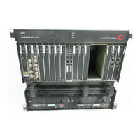
Lucent Technologies PacketStar PSAX 2300 User Manual (680 pages)
Multiservice Media Gateway
Brand:
Lucent Technologies
| Category:
Gateway
| Size: 6.35 MB
Table of Contents
User Guide
1
Legal Notices, Safety, and Regulatory Information
3
Trademarks
3
Notices
3
Warranty Information
3
Regulatory Standards Compliance
4
Safety Information
4
Table of Contents
5
1 Getting Started
35
Purpose of this Guide
35
Audience for this Guide
35
What You Should Know
35
Related Reading
36
Product Information Library
36
Printed Documents
36
Other Publications
36
Conventions
36
Text Conventions
36
Text Types Used in this Document
36
Command Description Table Example
37
Command Description Tables
37
Field Description Tables
37
Icons and Symbols
37
Field Description Table Example
38
Selecting Options, Fields, and Commands
38
Help Information
39
System Responses to Selecting Options, Fields, or Commands
39
Shortcut Keys for Navigating Console Interface Windows
39
Main Menu Help Window
40
Technical Support
41
About Lucent Technologies
41
For more Information
41
History
41
About the Packetstar PSAX Product Family
41
PSAX 1000 Multiservice Media Gateway
41
PSAX 1250 Multiservice Media Gateway
42
PSAX 2300 Multiservice Media Gateway
42
PSAX 4500 Multiservice Media Gateway
42
Comments on this Guide
43
2 Hardware Description
45
Overview of this Chapter
45
System Features
45
System Hardware Components
45
DC Power Supply Module
45
Functional Description
46
Chassis
46
PSAX 2300 Multiservice Media Gateway
46
Backplane
47
Power Supply Modules
47
Stratum 3-4 Module
48
CPU4 Module
49
CPU2 Module
50
CPU4 Module
50
Alarm Module
51
CPU2 Module
51
Alarm Module
52
Chapter 2 Hardware Description
52
Example Configuration with the Alarm Module
52
Hardware Specifications
53
Chassis Hardware Specifications
53
Chassis Specifications
53
System Environmental Specifications
53
Power Supply Module Specifications
54
Stratum 3-4 Module Specifications
54
Alarm Module Specifications
55
CPU2 Module Specifications
55
CPU4 Module Specifications
55
Module Performance and Power Specifications
56
Packetstar I/O and Server Modules Specifications
56
Physical Hardware Specifications for PSAX I/O and Server Modules
56
Physical Hardware Specifications for the Alarm Module
56
Performance and Power Specifications for the PSAX Modules
57
3 System Features
63
Overview of this Chapter
63
System Capabilities
63
User Benefits
63
Feature Highlights
63
Interface Architecture
64
Connections Supported
65
Permanent Virtual Circuit (PVC) Connections
65
Soft Permanent Virtual Circuit (SPVC) Connections
65
SPVC Reconnection Priority Scheme
66
Sample SPVC Reconnection Prioritization Scheme
67
Sample User-Defined Priority Scheme for Reconnecting SPVC ATM IMA Links
67
Modification of Parameters for Active SPVC Connections
68
Switched Virtual Circuit (SVC) Connections
68
Call States
69
SVC Functional Description
69
User Interfaces
71
Circuit Emulation Service
71
Circuit Emulation Service for the Multiserial Module
72
Dynamic Bandwidth Circuit Emulation Service
72
SPVC Support for CES
72
DS1 Service
73
DS3 Service
73
Dynamic CAC
73
HDLC Passthrough Bit Inversion
73
Interim Interswitch Signaling Protocol (IISP) Interface
74
Overview
74
Private Network-Network Interface (PNNI) 1.0
74
PNNI Features Supported by the PSAX Systems
75
PNNI Peer Group Dynamics
75
PNNI Hierarchies
76
PNNI Topology State Element (PTSE) Information
76
ATM Maintenance
78
PNNI Hierarchical Topology Showing Three Node Levels
78
Integrated Link Management Interface (ILMI)
79
ATM Terminal Emulation
80
ATM UNI 4.0 Signaling
80
ILMI over PNNI Overview
80
Load Balancing for IISP and PNNI
80
Automatic Use of IMA Links
81
IMA Configuration Considerations
81
Inverse Multiplexing over ATM (IMA)
81
Frame Relay-To-ATM Interworking
83
Frame Relay-To-Frame Relay Interworking
83
FRF.5 Encapsulating Frames
83
FRF.8 Converting Frames
83
GR-303 Interface
83
Inverse Address Resolution Protocol (ARP)
83
CAS Refresh Rates in the On-Hook State
85
Fax/Modem Master/Slave Support
85
Idle Channel Suppression Support for the Cellpipe IAD
85
Interoperability
85
Dynamic Bandwidth Allocation
86
Network Management
87
DBA-Controlled Backplane Traffic
87
Network Management Options
88
Simple Network Management Protocol Version 3
89
Navis Aqueview ® Element Management System
90
PSAX System Software Features
90
Bulk Statistics Collection
90
Connection Gateway API
91
Connection Gateway API Overview
91
PSAX System as a TCP Client/Server for the Connection Gateway API
91
PSAX System as a TCP Client Device
92
PSAX System as a TCP Server Device
92
Fractional PRI Support
93
PNNI Support
93
DS1 ANI In-Line Codes for Loopbacks
93
DS0A Non-Latched Loop Codes
94
PSAX System Traffic Protection Capabilities
95
1:1 Traffic Protection Patch Panel Module
95
APS/MSP Protection on the Optical Modules
97
Interface Protection Group Feature
98
Alternate Rerouting Using Dual-Homed Pvcs
99
Typical Interface Protection Group Configuration
99
Firmware Release Control
101
Automatic Traffic Rerouting Using Dual-Homed Pvcs
101
Forward Error Correction
102
H.248 Media Gateway Access Protocol
103
Forward Error Correction Automatic Rate Options
103
Interface and Connection Naming
104
Internet Protocol (IP) Throttling
105
LANET Protocol
106
Relationship between LANET and the OSI Model
107
LANET Frame Structure
108
Operations, Administration, and Maintenance (OAM)
109
Overview of OAM
109
OAM ATM Layer Flows
110
OAM Cell Fields
110
OAM F4 Flows
111
OAM F5 Flows
111
OAM Hierarchy
111
ATM Layer OAM Functions
112
Packet Pipe AAL5-To-AAL2 Wireless Trunking for Mobile Voice
113
OAM Activation/Deactivation Cells
113
SNMP Trap Descriptions
114
CBR and VBR Service-Level Priorities
115
ATM Traffic Management
116
Guaranteed Frame Rate
116
UPC Support
116
Usage Parameter Control
116
Early Packet Discard
117
Cell Bus Traffic Shaping Occurs on Egress to the Backplane
118
Cell Bus Traffic Shaping Using the Input Cell-Selection Algorithm
119
ATM Traffic Shaping
120
Overview of ATM Traffic Shaping
120
Configuring ATM Traffic Shaping for HDLC, Frame Relay, and Ethernet Virtual Channels
121
Sample ATM Traffic Shaping Flow
121
Task Summary for Implementing ATM Traffic Shaping
122
VBR ATM Traffic Shaping Priorities
122
ATM Traffic Shaping for CBR and VBR-Rt
123
How the ATM Traffic Shaping Algorithm Works
123
Maximum Number of ATM Traffic-Shaped Connections
123
ATM Traffic Shaping Table Sample Queue 1 Values
124
Connection Egress Priority on PSAX Modules Supporting ATM Traffic Shaping
125
Formula for Determining the PCR of an ATM Traffic-Shaped Connection
125
ATM Traffic Shaping Capabilities by Module
126
ATM Traffic Shaping Capabilities by PSAX Module
126
PSAX Modules Supporting Virtual Interfaces
128
Sample Uses of Virtual Interfaces
128
Virtual Interfaces
128
ATM Traffic Shaping, UPC Support, and VI Support Configuration Compatibility
129
Configuration Compatibility for ATM Traffic Shaping, UPC, and VI
129
Configuration Window
129
Combining the UPC Feature and Either the TS or VI Feature on a Connection
130
V5.2 European IDLC
130
Voice Compression
130
Voice Processing
131
Echo Cancellation
131
Wireless Mobile Voice Backhaul
132
Packetpipe AAL5-To-AAL2 Wireless Trunking from Cell Site to MSC for Mobile Voice
133
Virtual Routing
133
Enhanced Router and Example Configuration
134
Virtual Router Concept
134
End-To-End Continuity Check
135
Secure Telephone Unit Third Generation (STU-III) Secure Mode
135
Voice Path Assurance
135
GSM Voice Traffic Compression
136
System Performance
136
Optimized Bootup
136
Synchronization of PSAX System Software on Redundant Cpun Modules
137
Maintenance Testing on DS1 Interfaces
138
Reduction in Post-Dial Delay
138
System Security
138
RADIUS Server Authentication for PSAX System Access
138
PSAX System Access Authentication Via RADIUS Servers
139
ATM Security on Interfaces and Connections
140
PSAX Module Features
140
4 Using VT100 Terminal Emulation
141
Overview of this Chapter
141
Setting up the Windows Hyperterminal Emulator
141
Starting the Hyperterminal Program
141
Connection Description Window
142
Connect to Window
142
COM1 Properties Window
143
Windows Hyperterminal Settings
143
Connecting a Dialup Modem to the Chassis
144
PSAX 2300 Multiservice Media Gateway System Logon Window
144
Advertisement
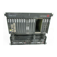
Lucent Technologies PacketStar PSAX 2300 User Manual (748 pages)
PSAX Multiservice Media Gateways
Brand:
Lucent Technologies
| Category:
Gateway
| Size: 10.5 MB
Table of Contents
Table of Contents
5
User Guide
1
Legal Notices, Safety, and Regulatory Information
3
Trademarks
3
Notices
3
Warranty Information
3
Regulatory Standards Compliance
4
Safety Information
4
Table of Contents
5
List of Figures
23
List of Tables
31
Getting Started
41
Purpose of this Guide
41
Audience for this Guide
41
What You Should Know
41
Related Reading
42
Other Publications
42
Printed Documents
42
Product Information Library
42
Conventions
42
Text Types Used in this Document
42
Text Conventions
42
Command Description Tables
43
Field Description Tables
43
Icons and Symbols
43
Command Description Table Example
43
Selecting Options, Fields, and Commands
44
Field Description Table Example
44
Help Information
45
System Responses to Selecting Options, Fields, or Commands
45
Shortcut Keys for Navigating Console Interface Windows
45
Main Menu Help Window
46
About Lucent Technologies
47
About the Packetstar PSAX Product Family
47
For more Information
47
History
47
PSAX 1000 Multiservice Media Gateway
47
Technical Support
47
PSAX 1000 Multiservice Media Gateway
51
Hardware Description
51
Front View of the PSAX 1000 Chassis
53
Rear View of the PSAX 1000 Chassis
53
PSAX 1000 Chassis Hardware Specifications
54
PSAX 1000 System Environmental Specifications
55
PSAX 1250 Multiservice Media Gateway
55
PSAX 1250 Multiservice Media Gateway(19-In.)
56
PSAX 1250 Multiservice Media Gateway (23-In.)
56
PSAX 1250 48.26-CM (19-In.) Chassis Backplane
58
PSAX 1250 58.42-CM (23-In.) Chassis Backplane
59
PSAX 1250 Chassis Hardware Specifications
59
PSAX 1250 System Environmental Specifications
60
Packetstar PSAX 2300 Multiservice Media Gateway
61
PSAX 2300 Chassis Hardware Specifications
63
PSAX 2300 System Environmental Specifications
63
Packetstar PSAX 4500 Multiservice Media Gateway
65
Data Flow through the PSAX 4500 Midplane
67
Chassis Hardware Specifications
67
PSAX 1000 Stratum 3-4/-48 V DC Power Supply Module
69
PSAX 1000 Stratum 3-4/110/220 V Ac Power Supply Module
70
Stratum 3-4/24 V DC Power Supply Module
71
PSAX 1000 Stratum 3-4/Power Supply Module Specifications
74
PSAX 1250 110 Vac, 220 Vac, and -48 V DC Power Supply Modules
76
PSAX 2300/4500 -48 V DC Power Supply Module
78
Functional Description
79
PSAX 1250 Stratum 3-4 Module
80
Stratum 3-4 Module Specifications
81
PSAX 2300 Stratum 3-4 Module Specifications
82
PSAX 4500 Stratum 3-4 Module
83
Stratum 3-4 Module Traffic Switcher
87
PSAX 1000 CPU3 Module
89
PSAX 1000 CPU3 Module Specifications
89
PSAX CPU4 Module
91
CPU4 Module Specifications
91
PSAX 1000 Fan/Alarm Module
92
PSAX 4500 Alarm Module
93
Example Configuration with the PSAX 4500 Alarm Module
93
Generating Central Office Alarms
94
Alarm Outputs
95
Generating Central Office Alarms (Example)
95
Alarm and PSAX 4500 Alarm Module Alarm Generation Criteria
96
Alarm Relay Operation
97
Fan/Alarm Module Alarm Generation Criteria
97
Alarm and PSAX 4500 Alarm Module ALARM Connector Configuration
98
Chapter 2 Hardware Description
98
Fan/Alarm Module ALARM Connector Configuration
99
Audible Alarm Cutoff (ACO)
100
Generating Alarms
100
Monitoring and Reporting on External Events
101
Monitoring and Reporting on External Events (Example)
101
Control Outputs
102
Control Output Relay Configuration
102
Remote Status Inputs
103
Activating Supplemental Air Conditioning
103
Monitoring and Reporting on Door Sensors
103
6-Port Multiserial Modules
104
I/O and Server Modules
104
Optimizing I/O and Server Module Placement
104
PSAX 1000 Chassis
104
PSAX 4500 Chassis
104
PSAX 4500 Midplane Slot Structure
104
Module Performance and Power Consumption
105
Performance and Power Specifications for the PSAX Modules
106
Feature Highlights
113
Overview of this Chapter
113
System Capabilities
113
System Features
113
User Benefits
113
Connections Supported
115
Interface Architecture
115
Permanent Virtual Circuit (PVC) Connections
115
Soft Permanent Virtual Circuit (SPVC) Connections
115
SPVC Reconnection Priority Scheme
116
Sample SPVC Reconnection Prioritization Scheme
117
Sample User-Defined Priority Scheme for Reconnecting SPVC ATM IMA Links
117
Modification of Parameters for Active SPVC Connections
118
SPVC Auto-Restart
118
Switched Virtual Circuit (SVC) Connections
118
Call States
119
SVC Functional Description
119
SVC Call State Transition Messages
120
System
121
User Interfaces
121
Circuit Emulation Service
122
Circuit Emulation Service for the 6-Port Multiserial Module
122
Dynamic Bandwidth Circuit Emulation Service
122
SPVC Support for CES
122
DS1 Service
123
DS3 Service
123
Dynamic CAC
123
HDLC Passthrough Bit Inversion
124
Interim Interswitch Signaling Protocol (IISP) Interface
124
Overview
124
Private Network-Network Interface (PNNI) 1.0
124
PNNI Features Supported by the PSAX Systems
125
PNNI Peer Group Dynamics
126
PNNI Topology State Element (PTSE) Information
126
PNNI Hierarchies
127
ATM Maintenance
128
PNNI Hierarchical Topology Showing Three Node Levels
128
Integrated Link Management Interface (ILMI)
129
Path and Connection Trace
129
ATM Terminal Emulation
130
ILMI over PNNI Overview
130
Load Balancing for IISP and PNNI
130
ATM UNI 4.0 Signaling
131
Automatic Use of IMA Links
131
IMA Configuration Considerations
131
Inverse Multiplexing over ATM (IMA)
131
Frame Relay-To-ATM Interworking
133
FRF.5 Encapsulating Frames
133
FRF.8 Converting Frames
133
Inverse Address Resolution Protocol (ARP)
133
Frame Relay-To-Frame Relay Interworking
134
GR-303 Interface
134
CAS Refresh Rates in the On-Hook State
135
Fax/Modem Master/Slave Support
135
Dynamic Bandwidth Allocation
136
Idle Channel Suppression Support for the Cellpipe IAD
136
Interoperability
136
DBA-Controlled Backplane Traffic
137
Network Management
138
Network Management Options
138
Simple Network Management Protocol Version 3
139
Navis EMS-PSAX System
140
Bulk Statistics Collection
141
Connection Gateway API
141
Connection Gateway API Overview
141
PSAX System Software Features
141
PSAX System as a TCP Client/Server for the Connection Gateway API
142
PSAX System as a TCP Client Device
142
Fractional PRI Support
143
PNNI Support
143
PSAX System as a TCP Server Device
143
DS0A Non-Latched Loop Codes
144
DS1 ANI In-Line Codes for Loopbacks
144
N:1 Traffic Protection with the PSAX 4500 System
145
PSAX System Traffic Protection Capabilities
145
N:1 Traffic Protection Scheme on the PSAX 4500 System
148
1:1 Traffic Protection with the PSAX 1000 System
149
1:1 Protection Scheme on the PSAX 1000 System
151
1:1 Traffic Protection with the PSAX 24-Port RJ Protection Patch Panel
152
1:1 Protection Scheme on the PSAX System
154
APS/MSP Protection on the Optical Modules
155
Line Defect Protection
155
Interface Protection Group with ATM Interfaces
156
Typical Interface Protection Group Configuration
157
Alternate Rerouting Using DHPVC
158
Firmware Release Control
159
Automatic Traffic Rerouting Using Dhpvcs
159
Forward Error Correction
160
Forward Error Correction Automatic Rate Options
161
H.248 Media Gateway Access Protocol
162
Interface and Connection Naming
162
Internet Protocol (IP) Throttling
164
LANET Protocol
164
Relationship between LANET and the OSI Model
165
Operations, Administration, and Maintenance (OAM)
166
Overview of OAM
166
LANET Frame Structure
166
OAM Cell Characteristics
167
OAM Cell Fields
168
OAM ATM Layer Flows
169
OAM F4 Flows
170
OAM F5 Flows
170
OAM Hierarchy
170
Modules Supporting OAM Flows
171
PSAX Modules Supporting OAM Flows
171
ATM Layer OAM Functions
172
OAM Activation/Deactivation Cells
173
Packetpipe AAL5-To-AAL2 Wireless Trunking for Mobile Voice
174
SNMP Trap Descriptions
174
CBR and VBR Service-Level Priorities
175
Traffic Management Using the Aqueman Algorithm
175
ATM Traffic Management
176
Guaranteed Frame Rate
176
UPC Support
177
Usage Parameter Control
177
Adjustable Queue Depth
178
ATM Traffic Shaping
178
Early Packet Discard
178
Overview of ATM Traffic Shaping
178
Configuring ATM Traffic Shaping
179
Sample ATM Traffic Shaping Flow
179
ATM Traffic Shaping Priorities
180
Task Summary for Implementing ATM Traffic Shaping
180
ATM Traffic Shaping Capabilities by PSAX Module
181
ATM Traffic Shaping for CBR and VBR-Rt
181
Connection Egress Priority on PSAX Modules Supporting ATM Traffic Shaping
181
Maximum Number of ATM Traffic-Shaped Connections
181
ATM Traffic Management Capabilities by Module
182
Virtual Interfaces
183
Sample Uses of Virtual Interfaces
184
Combining the UPC Feature and Either the TS or VI Feature on a Connection
185
ATM Traffic Shaping, UPC Support, and VI Support Configuration Compatibility
185
Packetpipe AAL5-To-AAL2 Wireless Trunking from Cell Site to MSC for Mobile Voice
189
Virtual Router Concept
190
Route Server and Example Configuration
191
Enhanced Router and Example Configuration
191
End-To-End Continuity Check
192
System
194
System Security
198
PSAX System Access Authentication Via RADIUS Servers
199
Connection Description Window
204
Starting the Hyperterminal Program
204
Connect to Window
205
COM1 Properties Window
205
Windows Hyperterminal Settings
206
PSAX System Logon Window Field Descriptions
211
Console Interface Main Menu Options and Commands
213
User Options Window-Authentication Mode Hybrid Selected
216
User Options Window Field Descriptions (RADIUS Server Fields)
218
Permissions for PSAX-Defined Usernames
220
User Options Window-Logged on as Username Readwrite
221
User Options Window-Logged on as Username Readonly
222
User Options Fields)
222
User Options Window Field Descriptions
222
ASCII Characters Permitted for Use in Passwords
224
Site-Specific Menu Window (no System Options Configured)
227
Site-Specific Menu Options Descriptions
228
System Identification Panel on the Site-Specific Configuration Window Field Descriptions
231
Site-Specific Configuration Window
234
Master ATM Address and OAM Related Data Panel on the Site-Specific Configuration Window Field Descriptions
234
Site-Specific Configuration Window Commands
234
Window Field Descriptions
234
System Related Data Panel on the Site-Specific Configuration Window
236
System Date and Time Panel on the Site-Specific Configuration Window
237
TCP Server Configuration Window Commands
239
TCP Server Configuration Window Field Descriptions
240
Site-Specific Menu Window
242
Call Control Resource Allocation Configuration Window Commands
243
Call Control Resource Allocation Configuration Window Field Descriptions
243
Call Control Resource Allocation Configuration Window Field Descriptions
244
Diagnostics Menu
251
Sample IUA Layer Configuration for the OMG and TMG Sides
261
IUA Layer Configuration Window Commands
261
IUA Layer Configuration Window Field Descriptions
261
Interface Protection Feature Configuration Window
263
Protection Group Table Window
264
Interface Protection Feature Configuration Window Commands
264
Protection Group Table Window Commands
264
Protection Group Configuration Window
265
Protection Group Configuration Window Commands
265
Protection Group Configuration Window Field Descriptions
265
Interface Protection Table Window
267
Interface Protection Table Window Commands
267
Interface Protection Configuration Window Commands
268
Interface Protection Configuration Window
269
Interface Protection Configuration Window Field Descriptions
269
N to M Protection Feature Menu Window (N:1 Protection)
270
N to M Protection Group Table Window (N:1 Protection)
271
N to M Protection Group Table Window Commands
271
N to M Protection Group Configuration Window (N:1 Protection)
272
N to M Protection Group Configuration Window (1:1 Protection)
272
N to M Protection Group Configuration Window Commands
273
N to M Protection Group Configuration Window Field Descriptions
273
N to M Protection Feature Menu Window
275
N to M Protection Table Window Commands
277
N to M Protection Table Window Field Descriptions
277
N to M Protection Configuration Window
279
N to M Protection Configuration Window Commands
279
N to M Protection Configuration Window Field Descriptions
279
The IP Throttling Window (Disabled)
282
The IP Throttling Window (Enabled)
282
IP Throttling Configuration Window Commands
282
IP Throttling Configuration Window Field Descriptions
283
Trap Activation Table Window Commands
287
Trap Activation Table
288
Trap Activation Table Window Field Descriptions
288
Bulk Statistics Configuration Window
290
Bulk Statistics Configuration Window Commands
290
Bulk Statistics Configuration Window Field Descriptions
290
Sample Equipment Configuration Window on a PSAX 1000 System
293
Sample Equipment Configuration Window on a PSAX 1250
293
Sample Equipment Configuration Window on a PSAX 2300 or PSAX 4500 System
294
Sample Equipment Configuration Window on a PSAX 1000, PSAX 2300, or PSAX 4500 System
294
Equipment Configuration Window Commands
295
Equipment Configuration Window Field Descriptions
296
Module Alarm Status Descriptions on the Equipment Configuration Window
298
Stratum Configuration Window (Freerun)
300
Stratum Configuration Window (Linetiming Synchronization)
300
Stratum Configuration Window Commands
301
Stratum Configuration Window Field Descriptions
301
Save Configuration [Modified] (before Saving)
309
Messages Generated after the Save Configuration Process
309
PNNI System-Wide Configuration Menu Window
312
PNNI System-Wide Configuration Window Commands
312
PNNI Node Table Window Commands
314
PNNI Node Table Window Field Descriptions
314
PNNI Node Configuration Window Commands
316
PNNI Node Configuration Window Field Descriptions
316
Modifying a Configured PNNI Node
319
PNNI Node PGL Configuration
320
PNNI Node PGL Configuration Window Field Descriptions
320
PNNI Node Timer Configuration Window
323
PNNI Node Timer Configuration Window Field Descriptions
323
PNNI Node SVCC Configuration Window
326
PNNI Node SVCC Configuration Window Field Descriptions
326
PNNI Scope Mapping Configuration
328
PNNI Scope Mapping Configuration Window Commands
328
PNNI Scope Mapping Configuration Window Field Descriptions
328
PNNI Route Address Table Window
331
PNNI Route Address Table Window Commands
331
PNNI Local Route Address through Interface Index Window
332
PNNI Route Address Table Window Field Descriptions
332
PNNI Route Address Configuration Window
333
PNNI Local Route Address through Interface Index Window Commands
333
PNNI Route Address Configuration Window Commands
333
PNNI Route Address Configuration Window Field Descriptions
334
PNNI Metrics Table Screen
337
PNNI Metrics Table Screen Commands
337
PNNI Metrics Configuration Screen
338
PNNI Metrics Table Screen Field Descriptions
338
PNNI Metrics Configuration Screen Commands
339
PNNI Metrics Configuration Screen Field Descriptions
339
PNNI Summary Address Table Window
341
PNNI Summary Address Table Window Commands
342
PNNI Summary Address Table Window Field Descriptions
342
PNNI Summary Address Configuration Window
343
PNNI Summary Address Configuration Window Commands
343
PNNI Summary Address Configuration Window Field Descriptions
343
PNNI Map Table Window
345
PNNI Map Table Window Commands
346
PNNI Map Table Window Field Descriptions
346
PNNI Map Information Window
347
PNNI Map Information Window Commands
347
PNNI Map Information Window Field Descriptions
347
PNNI Map Node Table Window Commands
349
PNNI Map Node Table Window
350
PNNI Map Node Information Window Command
350
PNNI Map Node Table Window Field Descriptions
350
PNNI Map Node Information Window
351
PNNI Map Node Information Window Field Descriptions
351
PNNI Map Address Table Window
354
PNNI Map Address Table Window Commands
354
PNNI Map Address Table Window Field Descriptions
354
PNNI Map Address Information Window
355
PNNI Map Address Information Window Commands
355
PNNI Map Address Information Window Field Descriptions
355
PNNI Link Table Window
357
PNNI Link Table Window Commands
357
PNNI Link Information Window
358
PNNI Link Information Window Commands
358
PNNI Link Table Window Field Descriptions
358
PNNI Link Configuration Window Field Descriptions
359
PNNI Svccrcc Table Window
362
PNNI Svccrcc Table Window Commands
362
PNNI SVCC RCC Table Window Field Descriptions
363
PNNI SVCC RCC Information Window Commands
364
PNNI SVCC RCC Information Window Field Descriptions
364
PNNI Neighbor Peer Table Window Commands
366
PNNI Neighbor Peer Table Window
367
PNNI Neighbor Peer Information Window Commands
367
PNNI Neighbor Peer Table Window Field Descriptions
367
PNNI Neighbor Peer Information Window
368
PNNI Neighbor Peer Information Window Field Descriptions
368
PNNI Neighbor Peer Port Table Window
370
PNNI Neighbor Peer Port Table Window Commands
370
PNNI Neighbor Peer Port Table Window Field Descriptions
371
PNNI PTSE Table Window
372
PNNI PTSE Table Window Commands
372
PNNI PTSE Information Window
373
PNNI PTSE Table Window Field Descriptions
373
PNNI Route TNS Table Window Commands
373
PNNI PTSE Information Window Field Descriptions
374
PNNI System Statistics Screen Window
375
PNNI System Statistics Screen Window Commands
376
PNNI System Statistics Window Field Descriptions
376
Site-Specific Menu Window-ATM Trunking Configuration Option Selected
381
ATM Trunking Local Node Configuration Window
381
ATM Trunking Local Node Configuration Window Commands
382
ATM Trunking Local Node Configuration Window Field Descriptions
382
ATM Trunking Remote IWF Table Window
384
ATM Trunking Remote IWF Table Window Commands
384
ATM Trunking Remote IWF Table Window Field Descriptions
384
ATM Trunking Remote IWF Configuration Window Commands
385
ATM Trunking Remote IWF Configuration Window Field Descriptions
386
ATM Trunking Sig VCC Table Window
388
ATM Trunking Signal VCC Table Window Commands
388
ATM Trunking Signal VCC Table Window Field Descriptions
388
ATM Trunking Sig VCC Configuration Window
389
ATM Trunking Signal VCC Configuration Window Commands
389
ATM Trunking Signal VCC Configuration Window Field Descriptions
390
ATM Trunking Bearer VCC Table Window
393
ATM Trunking Bearer VCC Table Window Commands
393
ATM Trunking Bearer VCC Table Window Field Descriptions
394
ATM Trunking Bearer VCC Configuration Window
395
ATM Trunking Bearer VCC Configuration Window Commands
395
ATM Trunking Bearer VCC Configuration Window Field Descriptions
396
ATM Trunking Bearer VCC Parameters Window
403
ATM Trunking Bearer VCC Parameters Window Commands
404
ATM Trunking Bearer VCC Parameters Window Field Descriptions
404
ATM Trunking Narrowband Routing Table Window
408
ATM Trunking Narrowband Routing Table Window Commands
408
ATM Trunking Narrowband Routing Table Window Field Descriptions
408
ATM Trunking Broadband Routing Table Window
409
ATM Trunking Broadband Routing Table Window Commands
410
ATM Trunking Broadband Routing Table Window Field Descriptions
410
ATM Trunking Data Channel Table
411
ATM Trunking Data Channel Table Window Commands
411
ATM Trunking Data Channel Table Window Field Descriptions
411
ATM Trunking Bearer VCC Profile Config Table Window
413
ATM Trunking Bearer VCC Profile Config Table Window Commands
413
ATM Trunking Bearer VCC Profile Config Table Window Field Descriptions
413
ATM Trunking Bearer VCC Profile Configuration Window
414
ATM Trunking Bearer VCC Profile Configuration Window Commands
414
ATM Trunking Bearer VCC Profile Configuration Window Field Descriptions
414
V5.2 Voice Switch Interoperability
420
Pstn Configuration
421
V5.2 IAD Interoperability
421
Call Control Resource Allocation Configuration Window Commands
427
V5 Configuration Window
435
V5 Interface Configuration Menu Window Commands
435
V5 Resource Allocation Configuration Window
436
V5 Resource Allocation Configuration Window Commands
436
V5 Resource Allocation Configuration Window Field Descriptions
436
V5 DSP over Subscription Table Window
439
V5 DSP over Subscription Table Window Commands
439
V5 DSP over Subscription Table Window Field Descriptions
440
V5 DSP Resource Pool over Subscription Configuration Window
441
V5 DSP Resource Pool over Subscription Configuration Window Commands
441
V5 DSP Resource Pool over Subscription Configuration Window Field Descriptions
442
V5 Interface Table Window
443
V5 Interface Table Window Commands
443
V5 Interface Table Window Field Descriptions
444
V5 Interface Configuration Window Commands
445
V5 Interface Configuration Window
446
V5 Interface Configuration Window Field Descriptions
446
V5 Intf Variant Table Window
448
V5 Interface Variant Table Window Field Descriptions
448
V5 Intf Variant Table Window Commands
448
V5 Interface Variant Configuration Window Commands
450
V5 Interface Variant Configuration Window
451
V5 Interface Variant Configuration Window Field Descriptions
451
V5 Physical C-Channel Configuration Table Window
453
V5 Physical C-Channel Configuration Table Window Commands
453
V5 Physical C-Channel Configuration Table Window Field Descriptions
454
V5 Physical C-Channel Configuration Window
455
V5 Physical C-Channel Configuration Window Commands
455
V5 Physical C Channel Configuration Window Field Descriptions
456
V5 E1 Link Configuration Table Window
458
V5 E1 Link Configuration Table Window Commands
458
V5 E1 Link Configuration Table Window Field Descriptions
459
V5 E1 Link Configuration Window
460
V5 E1 Link Configuration Window Field Descriptions
460
V5 E1 Interface Configuration Window
462
V5 E1 Interface Configuration Window Field Descriptions
463
V5 Time Slot Table
464
V5 Timeslot Table Window Commands
464
V5 Data Link Configuration Table
465
V5 Data Link Configuration Table Window Commands
465
V5 Data Link Configuration Table Window Field Descriptions
465
V5 Data Link Configuration Window
466
V5 Data Link Configuration Window Commands
466
V5 Data Link Configuration Window Field Descriptions
467
ATM Trunking Remote IWF Configuration Window
468
V5 User Port Table
469
V5 User Port Table Window Commands
469
V5 User Port Configuration Window for PSTN as Port Type
471
V5 User Port Configuration Window Commands
471
V5 User Port Configuration Window Field Descriptions
472
V5 User Port Configuration Window, Port Type ISDN Selected
477
V5 B Channels CID Table Window
478
V5 B Channel CID Table Window Commands
478
V5 B Channel CID Table Window Field Descriptions
478
Snmp Overview
479
Site-Specific Menu Window, SNMP Agent Selected
481
SNMP Agent System-Wide Configuration Window, Non-Root User View
481
SNMP Agent System-Wide Configuration Window, Root User View
482
SNMP Agent System-Wide Configuration Window Menu Options
482
Community String Table Window
483
Community String Table Window Commands
483
Community String Configuration Window
484
Community String Configuration Window Commands
484
Community String Table Window Field Descriptions
484
Community String Configuration Window Field Descriptions
485
Default USM User Information
485
Usm User Table Window
486
Usm User Table Window Commands
487
Usm User Table Window Field Descriptions
487
Usm User Creation Window
488
Usm User Creation Window Commands
488
Usm User Creation Window Field Descriptions
488
Usm User Key Change Configuration Window
490
Usm User Key Change Configuration Window Commands
490
Usm User Key Change Configuration Window Field Descriptions
491
Default VACM Access Groups
492
Vacm Access Table Window
493
Vacm Access Table Window Commands
493
Vacm Access Table Window Field Descriptions
494
Vacm Access Configuration Window Commands
495
Vacm Access Configuration Window
496
Vacm Access Configuration Window Field Descriptions
496
Default VACM Access Group Assignments
499
Valid VACM Group Assignment for USM Security Level
500
Vacm Security to Group Table Window
501
Vacm Security to Group Table Window Commands
501
Vacm Security to Group Table Window Field Descriptions
502
Vacm Security to Group Configuration Window
503
Vacm Security to Group Configuration Window Commands
503
Vacm Security to Group Configuration Window Field Descriptions
504
Notification Table Window
506
Notification Configuration Window
507
Notification Table Window Commands
507
Notification Table Window Field Descriptions
507
Notification Configuration Window Commands
508
Notification Configuration Window Field Descriptions
508
ATM UNI Interface ATM Security Window
513
ATM UNI Interface ATM Security Window Commands
513
ATM UNI Interface ATM Security Window Field Descriptions
514
ATM UNI Interface ATM Security Configuration Window (Integrity Security Service Only)
515
ATM UNI Interface ATM Security Configuration Window Field Descriptions
516
ATM UNI Interface ATM Security Configuration Window Commands
516
Security Services
520
ATM UNI Interface ATM Security Statistics Window
520
ATM UNI Interface ATM Security Statistics Window Commands
520
ATM UNI Interface ATM Security Statistics Window Field Descriptions
521
PNNI Node Configuration Window
524
ATM PNNI SVCC RCC Security Configuration Window (Integrity Security Service Only)
525
ATM PNNI SVCC RCC Security Configuration Window
525
And Confidentiality Security Services)
526
ATM PNNI SVCC RCC Security Configuration Window Commands
526
ATM PNNI SVCC RCC Security Configuration Window Field Descriptions
527
ATM PNNI SVCC RCC Security Statistics Window
531
ATM PNNI SVCC RCC Security Statistics Window Commands
531
ATM PNNI SVCC RCC Security Statistics Window Field Descriptions
532
ATM PNNI Interface ATM Security Window
535
ATM PNNI Interface ATM Security Window Commands
535
ATM PNNI Interface ATM Security Window Field Descriptions
536
ATM PNNI Interface ATM Security Configuration
537
Window - Signaling PVC (Integrity Security Service Only)
537
ATM PNNI Interface ATM Security Configuration Window - Signaling PVC (both Integrity Security and Confidentiality Services)
538
ATM PNNI Interface ATM Security Configuration - Signaling PVC
538
Window Commands
538
ATM PNNI Interface ATM Security Configuration - Signaling PVC Window Field Descriptions
539
ATM PNNI Interface ATM Security Statistics - Signaling PVC Window
542
ATM PNNI Interface ATM Security Statistics - Signaling PVC Window Commands
543
ATM PNNI Interface ATM Security Statistics - Signaling PVC Window Field Descriptions
543
ATM PNNI Interface ATM Security Configuration - Routing PVC Window (Integrity Security Service Only)
546
ATM PNNI Interface ATM Security Configuration - Routing PVC Window (both Integrity Security and Confidentiality Services)
546
ATM PNNI Interface ATM Security Configuration - Routing
547
ATM PNNI Interface ATM Security Configuration - Routing PVC
547
PVC Window Commands
547
ATM PNNI Interface ATM Security Statistics - Routng PVC Window
551
ATM PNNI Interface ATM Security Statistics - Routing PVC Window Commands
551
ATM PNNI Interface ATM Security Statistics - Routing PVC Window Field Descriptions
552
ATM Security Agents Table Window (Populated)
554
ATM Security Agents Table Window Commands
555
ATM Security Agents Table Window Field Descriptions
555
ATM Security Statistics Window
557
ATM Security Statistics Window Commands
557
ATM Security Statistics Window Field Descriptions
558
Diagnostics Menu Window
562
Diagnostics Menu Window Commands
563
System Information Window
564
System Information Window Commands
564
System Information Window Field Descriptions
565
Module Connection Count Window
568
Module Connection Count Table Window Commands
568
Module Connection Count Table Window Field Descriptions
568
Cell Test Diagnostics Window
570
Cell Test Diagnostics Window Commands
570
Cell Test Diagnostics Window Field Descriptions
571
Cell Test Payload Configuration Window
572
Cell Test Payload Configuration Window Commands
572
Cell Test Payload Configuration Window Field Descriptions
573
Remote Reboot Configuration Window Commands
576
Unlock Shell / Ping Window
578
OAM Loopback Table Window Commands
580
OAM Loopback Table Window
581
OAM Loopback Window
581
OAM Loopback Table Window Field Descriptions
581
OAM Loopback Window Commands
582
OAM Loopback Window Field Descriptions
582
OAM Activate & Deactivate Table Window
585
OAM Activate & Deactivate Table Window Commands
585
OAM Activation - Deactivation Window
586
OAM Activation - Deactivation Window Commands
586
OAM Activation - Deactivation Window Field Descriptions
586
Tasks for Copying Database Configuration Files between the PSAX System and a Remote Storage Medium
594
Remote Database Operation Window
596
Remote Database Operation Window Commands
596
Remote Database Operation Window Field Descriptions
596
PSAX System Configuration Files
600
Software Version Configuration Window
602
XMODEM/YMODEM File Transfer Window (Send Options Panel Selected)
603
XMODEM/YMODEM File Transfer Window Commands
603
XMODEM/YMODEM File Transfer Window Commands
604
XMODEM/YMODEM File Transfer Window Field Descriptions
604
XMODEM/YMODEM File Transfer Window Field Descriptions
605
Connecting a Cable to the Standby (Backup) CPU Module
611
Tasks for Transferring Files to Your PSAX System
614
SRD Download Configuration Window
617
SRD Download Configuration Window Commands
618
SRD Download Configuration Window Field Descriptions
618
Error Status Code Values for the [Error Status] Field on the SRD Download Configuration Window Field Descriptions
619
Determining Whether to Proceed with System Upgrade
622
Migration of the Files During the PSAX System Upgrade
623
Determining Whether to Save Your Current System Configuration before Upgrade
624
Length of Time Required for Firmware Downloading
626
Setting up the Connection between the Modem and the PSAX System
628
Setting up the Connection between the PC Workstation, the Local Modem, and the Telephone Jack
628
The Software Version Configuration Window (Firmware Version Control Selected)
636
Firmware Version Control Window
638
Firmware Version Control Window Commands
638
Firmware Version Control Window Field Descriptions
639
AC Power Supply Connector Pin Configuration
643
AC Power Supply Connector Pin Assignments
643
Cpun Module CONSOLE Connector Pin Assignments
644
ETHERNET1 and ETHERNET2 Connector Pin Locations
645
Cpun Module ETHERNET1 and ETHERNET2 Connector Pin Assignments
645
RJ-12-To-DB9 Adapter Pin Assignments
645
Attaching the External Clock Connector
646
RJ-12-To-DB25 Adapter Pin Assignments
646
Stratum 3-4 Module Connector Pin Assignments
647
Stratum 3-4 Module RJ-45 Connector Pin Assignments
647
ALARM Connector Pin Locations on the Fan/Alarm Module
648
ALARM Cable with 26-Pin Connector and Pigtail
648
(Comcode 300164290
648
ALARM Connector Pin Assignments and Cable Pigtail Color Code
648
ALARM Connector Pin Assignments and Cable Pigtail Color Code
649
ALARM Connector Pin Locations on the Alarm Module
650
ALARM Connector Pin Locations on the PSAX 4500 Alarm Module
650
ALARM Cable with 26-Pin Connector and Pigtail
650
STATUS/CONTROL Connector Pin Locations on the Alarm Module
652
STATUS/CONTROL Connector Pin Locations on the PSAX 4500 Alarm Module
652
STATUS/CONTROL Cable with 44-Pin Connector and Pigtail
653
STATUS/CONTROL Connector Pin Assignments and Cable Pigtail Color Code (COMCODE 300164282
653
Direct Connection Configuration Diagram
656
Routed Connection Configuration Diagram
658
Hybrid Connection Configuration Diagram
664
Reference Information
669
Traffic Processing Options and Priority Queueing for Modules Supporting ATM Interfaces
671
Connection Release Cause Codes for Spvcs
673
Connection Type by Interface Type
677
Interface Type by I/O Module Type
679
PSAX System-Supported Quality of Service Categories
682
Mapping ATM Service Categories to PSAX System Priority Levels
683
ATM Traffic Shaping, UPC Support, and VI Support Configuration Compatibility
684
Combining the UPC Feature and Either the TS or VI Feature on a Connection
685
ATM Traffic Shaping CPS Calculation Table
685
I/O Module Transmit Clock Options
689
Packetstar PSAX Multiservice Media Gateway Modules
693
PSAX 1-Port STM-1 1+1 MSP Module Optical Specifications
732
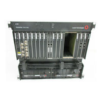
Lucent Technologies PacketStar PSAX 2300 User Manual (644 pages)
1-Port Channelized STS-1e, T1 Format Module
Brand:
Lucent Technologies
| Category:
Gateway
| Size: 4.89 MB
Table of Contents
Copyright and Legal Notices
3
Trademarks
3
Warranty Information
3
Software and Hardware Limited Warranties
3
Warranty Warnings
4
Regulatory Standards Compliance
4
Safety and Electromagnetic Compatibility (EMC)
4
Safety Information
7
Table of Contents
9
1 Getting Started
19
Purpose of this Guide
19
Audience for this Guide
19
What You Should Know
19
Related Reading
20
Lucent Technologies Information Products
20
Printed Documents
20
Product Information Library
20
Other Publications
20
About Lucent Technologies
20
History
20
For more Information
20
About the Packetstar ® PSAX Product Family
21
Text Conventions
22
Text Types Used in this Document
22
Icons and Symbols
23
Electrostatic Discharge Precautions
24
Grounding Wrist Straps
24
Floor Covering
24
Temperature and Humidity
24
Clothing
25
Handling PSAX System Components
25
Technical Support
25
Comments on this Guide
25
Before You Begin
25
2 Module Description
27
Overview of this Module
27
Software Features
28
Hardware Features
29
Hardware Specifications
29
Chassis Speed, Power Consumption, and Memory Allocation
29
Status Indicators
30
3 Configuring Ports and Channels Using the Console Interface
33
Overview of this Chapter
33
Before You Begin
33
Loopback Configuration Options
33
Setting the Values for Ports and Channels
35
Configuring a Virtual Port with One Channel
44
Configuring a Virtual Port with up to 24 Channels
48
Viewing Port Statistics
51
Saving the Equipment Configuration and Logging off
56
4 Configuring Ports and Channels Using the Aqueview ® System
59
Overview of this Chapter
59
Before You Begin
59
Loopback Configuration Options
59
Using the Right-Click Menu
60
Configuring Ports and Channels
60
Context-Sensitive Help
61
Configuring the Module
62
Physical Port Configuration
63
Virtual Port Configuration
67
Copying a Port Configuration
73
Channel Configuration
74
Viewing Port Statistics
76
5 Configuring the Interfaces Using the Console Interface
81
Overview of this Chapter
81
Configuring the ATM IISP User/Network Interfaces
81
Optimizing SVC Call Performance
82
Configuring the ATM IISP Interface
82
Configuring the ATM PNNI 1.0 Interface
87
Optimizing SVC Call Performance
87
Configuring the ATM PNNI 1.0 Interface
88
Configuring PNNI ILMI
94
Viewing PNNI ILMI Interface Statistics
97
Viewing PNNI Interface Statistics
98
Changing PNNI Values
100
Changing the Non-Administrative Weight Values for the ATM PNNI Interface
100
Configuring the ATM UNI 3.0/3.1 Interface
101
Configuring the Interface
101
Viewing ATM UNI Interface Statistics
107
Configuring ATM UNI ILMI
109
Displaying Registered Addresses
112
Viewing ILMI Statistics
112
Configuring the Circuit Emulation Interface
114
Configuring the Dynamic Bandwith Circuit Emulation Service Interface
117
Viewing Frame Relay Statistics
126
Viewing Frame Relay LMI Statistics
128
Changing Interface Field Values
130
Deleting an Interface
131
Configuring the HDLC Passthrough Interface
131
Viewing HDLC Pass through Interface Statistics
134
Advertisement
Lucent Technologies PacketStar PSAX 2300 User Manual (596 pages)
PSAX 6-Port DS1 IMA Module
Brand:
Lucent Technologies
| Category:
Gateway
| Size: 4.68 MB
Table of Contents
Copyright and Legal Notices
3
Trademarks
3
Warranty Information
3
Software and Hardware Limited Warranties
3
Warranty Warnings
4
Regulatory Standards Compliance
4
Safety and Electromagnetic Compatibility (EMC)
4
Telecommunications
5
Regulatory Statements
5
USA Regulatory Statements
5
FCC Part 68
5
Canadian Regulatory Statements
6
Issue 8
6
Version 8
7
Japanese Regulatory Statements
7
Jate
7
Safety Warnings and Information
9
Table of Contents
11
1 Getting Started
21
Purpose of this Guide
21
Audience for this Guide
21
What You Should Know
21
Related Reading
21
Lucent Technologies Information Products
21
Product Information Library
21
Printed Documents
22
About Lucent Technologies
22
History
22
For more Information
22
About the Packetstar® PSAX Product Family
22
Text Conventions
24
Text Types Used in this Document
24
Icons and Symbols
25
Electroststic Discharge Precautions
26
Grounding Wrist Straps
26
Floor Covering
26
Temperature and Humidity
26
Clothing
27
Handling Multiservice Media Gateway System Components
27
Technical Support
27
Comments on this Guide
27
Before You Begin
27
2 Module Description
29
Overview of this Module
29
Software Features
30
Hardware Features
31
Hardware Specifications
31
Chassis Speed, Power Consumption, and Memory Allocation
31
LED Indicators
32
3 Configuring Ports and Channels Using the Console
35
Overview of this Chapter
35
Before You Begin
35
Loopback Configuration Options
36
Configuring the Module
37
Configuring the 6-Port DS1 IMA Module
37
Configuring the IMA Ports
37
IMA Port and Channel Configuration
42
Port Statistics
46
IMA Groups
47
Saving Equipment Configuration and Logging off
52
4 Configuring Ports and Channels Using the Aqueview ® System
55
Overview of this Chapter
55
Before You Begin
55
Loopback Configuration Options
55
Using the Right-Click Menu
56
Configuring Ports and Channels
56
Context-Sensitive Help
57
Configuring the 6-Port DS1 IMA Module
58
Configuring the Module
59
IMA Port Configuration
59
Copying a Port Configuration
64
Channel Configuration
65
Viewing Port Statistics
67
IMA Virtual Channels
67
IMA Virtual Channel Configuration
68
Virtual Channel Configuration
68
Viewing Channel Details
72
IMA Channel Details
72
Lucent Technologies PacketStar PSAX 2300 User Manual (404 pages)
21-Port High-Density E1 Multiservice Module
Brand:
Lucent Technologies
| Category:
Gateway
| Size: 4.56 MB
Table of Contents
User Guide
1
Legal Notices, Safety, and Regulatory Information
3
Trademarks
3
Notice
3
Warranty Information
4
Software and Hardware Limited Warranties
4
Warranty Warnings
4
Safety Warnings and Information
4
Regulatory Standards Compliance
5
Safety and Electromagnetic Compatibility (EMC)
5
Telecommunications
5
Regulatory Statements
5
Table of Contents
11
Contents
12
List of Figures
18
Packetstar ® PSAX 21-Port High-Density E1 Multiservice Module User Guide, Issue 1 Release
24
1 Getting Started
27
Purpose of this Guide
27
Audience for this Guide
27
What You Should Know
27
Related Reading
28
Lucent Technologies Information Products
28
Other Publications
28
Printed Documents
28
Product Information Library
28
About Lucent Technologies
28
About the Packetstar PSAX Product Family
28
PSAX 1000 Multiservice Media Gateway
29
PSAX 1250 Multiservice Media Gateway
29
PSAX 2300 Multiservice Media Gateway
29
PSAX 4500 Multiservice Media Gateway
30
Conventions
31
Icons and Symbols
31
Text Types Used in this Document
31
Use of Command Description Tables
31
Text Conventions
31
Use of Field Description Tables
32
Command Description Table Example
32
Field Description Table Example
32
General Navigational Guidelines
33
Selecting Options, Fields, and Commands Using the Console Interface
33
System Responses to Selecting Options, Fields, or Commands
33
Selecting Menu Options and Fields in the Aqueview GUI
34
Shortcut Keys for Navigating Console Interface Windows
34
Selecting Multiple Menu Options or Buttons in Succession
34
Help Information
35
How Fields Are Displayed in the Aqueview GUI
35
Shortcut Keys for Navigating the Aqueview GUI
35
Technical Support
36
Main Menu Help Window
36
Before You Begin
37
Comments on this Guide
37
2 Module Description
39
Overview of this Module
39
Connection Options
40
21-Port High-Density E1 Multiservice Modules Connected to the PSAX 48-Port RJ Patch Panel
41
(Front View)
41
Software Features
42
Hardware Features
43
Hardware Specifications
43
Physical Hardware Specifications
43
Performance and Power Specifications
44
LED Indicators
44
LED Indicators for the 21-Port High-Density E1 Multiservice Module
45
3 Configuring Ports and Channels Using the Console Interface
49
Overview of this Chapter
49
Before You Begin
49
Loopback Configuration Options
49
Obtaining General Module Data and Accessing Ports and Channels
50
Loopback Configuration Options
50
Sample Equipment Configuration Window on a PSAX 1000 System
51
Sample Equipment Configuration Window on a PSAX 1250 System
52
Sample Equipment Configuration Window on a PSAX 2300 or PSAX 4500 System
52
Sample Equipment Configuration Window on a PSAX 1000, PSAX 2300, or PSAX 4500
53
Commands for the Equipment Configuration Window
54
Field Descriptions for the Equipment Configuration Window
54
Configuring the Module
56
Configuring HD E1 Ports
56
Configuring the Ports
56
Alarm Status Descriptions for Modules on the Equipment Configuration Window
56
Console Interface Main Menu (Equipment Configuration Selected)
57
Equipment Configuration Window (as Displayed on the PSAX 1250, PSAX 2300 and PSAX 4500 Console)
57
High-Density E1 Configuration Window
58
High-Density E1 Port and Channel Configuration Window
59
Field Descriptions for the High-Density E1 Port and Channel Configuration Window
61
Configuring a Port with One Channel
65
High-Density E1 Channel Configuration Window (One Channel Per Port)
65
High-Density E1 Channel Configuration Window
65
Field Descriptions for the High Density E1 Channel Configuration Window
68
Configuring a Port with Several Channels
69
High-Density E1 Channel Configuration Window (Several Channels Per Port)
69
High-Density E1 Ds0S Strap Display Window
70
Viewing Port Statistics
71
High-Density E1 Port Statistics Window
71
Field Descriptions for the High-Density E1 Port Statistics Window
72
Saving the Equipment Configuration and Logging off
73
Lucent Technologies PacketStar PSAX 2300 User Manual (268 pages)
4-Port Voice 2-Wire Office Module for the PacketStar PSAX Multiservice Media Gateways
Brand:
Lucent Technologies
| Category:
Telephone Accessories
| Size: 1.91 MB
Table of Contents
User Guide
1
Copyright and Legal Notices
3
Trademarks
3
Warranty Information
3
Software and Hardware Limited Warranties
3
Warranty Warnings
4
Regulatory Standards Compliance
4
Safety and Electromagnetic Compatibility (EMC)
4
Telecommunications
5
Regulatory Statements
5
USA Regulatory Statements
5
Canadian Regulatory Statements
6
Issue 8
6
Version 8
7
Safety Warnings and Information
9
Table of Contents
11
1 Getting Started
15
Overview of this Guide
15
Audience for this Guide
15
What You Should Know
15
Related Reading
16
Lucent Technologies Information Products
16
Product Information Library
16
Printed Documents
16
Other Publications
16
About Lucent Technologies
16
History
16
For more Information
16
About the Packetstar PSAX Product Family
17
Document Conventions
18
Text Types Used in this Document
18
Icons and Symbols
19
Electrostatic Discharge Precautions
20
Grounding Wrist Straps
20
Floor Covering
20
Temperature and Humidity
20
Clothing
21
Handling Multiservice Media Gateway System Components
21
Technical Support
21
Comments
21
Before You Begin
22
2 Module Description
23
Overview of this Chapter
23
4-Port Voice 2-Wire Office Module
24
Module Placement Requirements
24
Hardware Features
24
General Hardware Specifications
24
Chassis Speed, Power Consumption, and Memory Allocation
25
LED Indicators
25
Lucent Technologies PacketStar PSAX 2300 User Manual (156 pages)
for the PacketStar PSAX Multiservice
Brand:
Lucent Technologies
| Category:
Control Unit
| Size: 1.95 MB
Table of Contents
Legal Notices, Safety, and Regulatory Information
3
Trademarks
3
Notices
3
Warranty Information
4
Software and Hardware Limited Warranties
4
Warranty Warnings
4
Safety Warnings and Information
4
Regulatory Standards Compliance
4
Safety and Electromagnetic Compatibility
4
Regulatory Statements
5
European Union Regulatory Statement
5
CE Marking
5
Table of Contents
11
List of Figures
15
1 Getting Started
19
Purpose of this Guide
19
Audience for this Guide
19
What You Should Know
19
Related Reading
20
Lucent Technologies Information Products
20
Product Information Library
20
Printed Documents
20
Other Publications
20
About Lucent Technologies
20
About the Packetstar PSAX Product Family
20
PSAX 1000 Multiservice Media Gateway
21
PSAX 1250 Multiservice Media Gateway
21
PSAX 2300 Multiservice Media Gateway
21
PSAX 4500 Multiservice Media Gateway
22
Conventions
23
Text Types Used in this Document
23
Icons and Symbols
23
Text Conventions
23
Use of Command Description Tables
24
Use of Field Description Tables
24
Command Description Table Example
24
Field Description Table Example
24
General Navigational Guidelines
25
Selecting Options, Fields, and Commands Using the Console Interface
25
System Responses to Selecting Options, Fields, or Commands
25
Selecting Menu Options and Fields in the Aqueview GUI
26
Shortcut Keys for Navigating Console Interface Windows
26
Selecting Multiple Menu Options or Buttons in Succession
26
Help Information
27
How Fields Are Displayed in the Aqueview GUI
27
Shortcut Keys for Navigating the Aqueview GUI
27
Technical Support
28
Main Menu Help Window
28
Before You Begin
29
Comments on this Guide
29
Lucent Technologies PacketStar PSAX 2300 User Manual (194 pages)
DSP2x Voice Server Modules
Brand:
Lucent Technologies
| Category:
Gateway
| Size: 2.88 MB
Table of Contents
Trademarks
3
Notices
3
Warranty Information
3
Safety Warnings and Information
4
Electrostatic Discharge Precautions
4
Regulatory Standards Compliance
6
Safety and Electromagnetic Compatibility (EMC)
6
Regulatory Statements
6
Table of Contents
11
1 Getting Started
17
Overview of this Guide
17
Audience for this Guide
17
What You Should Know
17
Printed Documents
18
About Lucent Technologies
18
History
18
For more Information
18
About the Packetstar ® PSAX Product Family
18
PSAX 1000 Multiservice Media Gateway
18
PSAX 1250 Multiservice Media Gateway
19
PSAX 2300 Multiservice Media Gateway
19
PSAX 4500 Multiservice Media Gateway
19
Text Conventions
20
Text Types Used in this Document
20
Icons and Symbols
20
Use of Field Description Tables
21
Technical Support
24
Comments on this Guide
25
Before You Begin
25
2 Modules Description
27
Overview of the Dsp2X Voice Server Modules
27
Dsp2X Software Features
32
Dsp2X Hardware Features
33
DSP2E Voice Server for Wireless Backhaul Applications
33
DSP2F Packet Pipe Voice Server for AAL5-To-AAL2 Wireless Trunking Applications
33
DSP2D Voice Server Feature Matrix
34
Using the DSP2D, DSP2E, and DSP2F Voice Server Modules for AAL5-To-AAL2 Wireless Trunking Applications
35
Using the DSP2D Voice Server Module for GR-303 LES and 7 R/E™ Applications
37
Configuring the GR-303 LES Interface
37
Module Placement
37
DSP2C Voice Server Module Software Features
38
Emulated Algosets 2 and 3 on the DSP2C Module with Improved Features
38
DSP2C Fax Demodulation/Remodulation
38
DSP2C Module Feature Matrix
41
Dsp2X Voice Server Module Feature Details
43
Multiplexed or Nonmultiplexed AAL2
43
Dynamic DSP Resource Allocation
43
Failure Alarm
44
Caller ID/Flash Hook Signalling
44
Hybrid Algoset Configurations
44
OAM Support on the DSP2D Module
44
Previous System Software Release Version Compatibility
44
Semi-Permanent Virtual Circuit Support
44
Voice Processing
45
Silence Suppression
45
Input/Output PSAX Modules Compatible with Voice Processing
45
DSP2A and DSP2B Single-Algoset Voice Server Modules (System Release 6.2.0)
45
Hardware Features
47
Hardware Specifications
47
Chassis Speed, Power Consumption, and Memory Allocation Specifications
48
LED Indicators
48
Advertisement
Related Products
Lucent Technologies PacketStar PSAX 1250
Lucent Technologies PacketStar PSAX 1000
Lucent Technologies PacketStar PSAX 4500
Lucent Technologies PacketStar PSAX 60
Lucent Technologies PacketStar PSAX
Lucent Technologies PacketStar PSAX Series
Lucent Technologies PacketStar PSAX 20
Lucent Technologies Cajun P118LX
Lucent Technologies PortMaster OR-M
Lucent Technologies PortMaster PM-2
Lucent Technologies Categories
Telephone
Switch
Conference System
Software
Telephone System
More Lucent Technologies Manuals
Login
Sign In
OR
Sign in with Facebook
Sign in with Google
Upload manual
Upload from disk
Upload from URL