Lucent Technologies PacketStar PSAX 4500 User Manual
Multiservice media gateway
Hide thumbs
Also See for PacketStar PSAX 4500:
- User manual (722 pages) ,
- User manual (596 pages) ,
- User manual (54 pages)
Table of Contents
Advertisement
Quick Links
Download this manual
See also:
User Manual
Advertisement
Table of Contents

Subscribe to Our Youtube Channel
Related Manuals for Lucent Technologies PacketStar PSAX 4500


Summary of Contents for Lucent Technologies PacketStar PSAX 4500
- Page 1 ® PacketStar PSAX 4500 Multiservice Media Gateway User Guide Issue 1, August 2001 System Software Release 7.0 Doc. No.: 255-700-156...
- Page 2 Copyright © 2001 by Lucent Technologies. All rights reserved. For trademark, regulatory compliance, and related legal information, see the "Copyright and Legal Notices" section.
-
Page 3: Copyright And Legal Notices
This material is protected by the copyright laws of the United States and other countries. It may not be reproduced, distributed, or altered in any fashion by any entity (either internal or external to Lucent Technologies), except in accordance with applicable agreements, contracts or licensing, without the express written consent of the originating organization and the business management owner of the material. -
Page 4: Warranty Warnings
CAUTION: Modifying or tampering with PSAX chassis components may void your warranty. Any modification to this equipment not expressly authorized by Lucent Technologies may void your granted authority to operate such equipment. CAUTION: Air vents in the PSAX chassis are provided to aid in ventilation and to protect from overheating. -
Page 5: Regulatory Standards Compliance
Copyright and Legal Notices Regulatory Standards Compliance CAUTION: You must maintain a minimum 10.16 cm (4 in.) of clearance around the chassis for adequate airflow. Failure to adhere to this space requirement may result in equipment failure due to overheating. Failure to provide a minimum of 10.16 cm (4 in.) of clearance between this unit and any other device/structure will void your warranty. -
Page 6: Telecommunications
PSAX chassis is a label that contains the FCC registration number, in addition to other information. You must provide this information to the telephone company, if they request it. The FCC requires Lucent Technologies to provide you with the following information: 1. - Page 7 6. If you experience trouble with this equipment, or need repairs or warranty information, please refer to the Lucent Technologies InterNetworking Systems Global Warranty that accompanied your PSAX product shipment for instructions on obtaining technical support in your area.
- Page 8 Copyright and Legal Notices Regulatory Statements • Up to fifteen I/O, server, or blank faceplate modules consisting of the following: ~ 1-Port Channelized DS3 CES module, model 23N61 ~ 1-Port Channelized DS3 Multiservice module, model 23N60 ~ 1-Port Channelized STS-1e T1 module, model 23N62 ~ 1-Port DS3 Frame Relay module, model 20N03 ~ 1-Port DS3 IMA module, model 23N68 ~ 1-Port OC-12c/STM-4c 1+1 APS/MSP Multimode module, model...
-
Page 9: Canadian Regulatory Statements
Copyright and Legal Notices Regulatory Statements ~ Alarm module, model 20N79 ~ DSP2 Voice Server module, model 20N27 ~ DSP2A Voice Server module, model 20N29 ~ DSP2B Voice Server module, model 20N28 ~ DSP2C Voice Server module, model 23N27 ~ DSP2D Voice Server module, model 23N29 ~ PSAX 1250/2300 I/O or CPU Blank Faceplate, model 20N87 ~ Route Server module, model 20N41 ~ Tones and Announcements Server module, model 23N28... -
Page 10: Version 8
Copyright and Legal Notices Regulatory Statements The Ringer Equivalence Number (REN) assigned to the Voice 2-Wire Office module denotes the percentage of the total load to be connected to a telephone loop, which is used by the device, to prevent overloading. The termination on a loop may consist of any combination of devices subject only to the requirement that the total of the REN of all devices does not exceed 5. -
Page 11: European Union Regulatory Statement
European Union Regulatory Statement ® CE-Marking Hereby, Lucent Technologies declares that the PacketStar PSAX 1250 (-48 V dc), PSAX 2300, PSAX 4500, and PSAX AC 60 (-48 V dc) Multiservice Media Gateways are in compliance with the essential requirements and other relevant provisions of the following Council Directives: •... - Page 12 ¥²³²·¸¯¢ q¶¢¸½´³ ¸¬» }½¶º´¥¿¯ » ”²º·¬» ® t µ¥²·¬ CE ‚© ¸³ ´¥¶¢², ¬ Lucent Technologies, ¨¬°µ²© ¢¸ ¸¥ PacketStar PSAX1250 ( - 48Vdc), PSAX2300, PSAX4500, ¯¥ PSAXAC60 ( - 48Vdc) Multiservice Media Gateways ©²¥¶±³²¡¾³²¸¥ ±© ¸» ¦¥·¯Ÿ» ¥´¥¸ ·©» ¯¥ °³´Ÿ» ·¼©¸¯Ÿ»...
- Page 13 Normativa dell’Unione Europea ® Apposizione del La Lucent Technologies dichiara che i gateway multiservizio PacketStar marchio CE PSAX 1250 (-48 V dc), PSAX 2300, PSAX 4500 e PSAX AC 60 (-48 V dc), rispondono ai requisiti essenziali ed ad altre norme rilevanti delle seguenti direttive del Consiglio: •...
- Page 14 Internet-site met openbare toegang: http://www.lucent.com/ins/doclibrary Padrão Regulador da União Europeia CE-Marcação / A Lucent Technologies vem por este meio declarar que os Concentradores de ® Características Acesso PacketStar PSAX 1250 (-48 V dc), PSAX 2300, PSAX 4500 e PSAX AC 60 (-48 V dc) obedecem aos requisitos essenciais e a outras disposições relevantes das seguintes Directivas do Conselho:...
-
Page 15: Japanese Regulatory Statements
Copyright and Legal Notices Regulatory Statements Multiservice Media Gateways uppfyller de väsentliga kraven och andra relevanta bestämmelser som gäller enligt följande Europarådsdirektiv: • Lågspänning 72/23/EEC • Elektromagnetisk kompatibilitet (EMC) 89/336/EEC • Radioutrustning och telekommunikationskopplingsutrustning 1999/5/EC ® Lucent PacketStar PSAX Multiservice Media Gateways, som är placerad i EEA (European Economic Area), är avsedd för att anslutas till E1, E3, STM-1 och STM-4c nätverk. -
Page 16: Class A Electromagnetic Compatibility (Emc) Regulatory Statement
Copyright and Legal Notices Regulatory Statements Table 1. JATE Approved Modules Module Jate Model Num- Approval Module Description Number 20N62 1-Port STM-1 Multimode with AQueMan L00-0198 (STM-1 (MM AQ)) 20N63 1-Port STM-1 Single-Mode with AQueMan L00-0198 (STM-1 (SM AQ)) 20N64 1-Port STM-1 Multimode with Traffic Shaping L00-0198 (STM-1 (MM TS)) -
Page 17: Safety Information
Safety Information Overview of This Section When installing and operating the PSAX 4500 Multiservice Media Gateway, follow the safety guidelines provided below to help prevent serious personal injury and damage to the PSAX 4500 equipment. Please read all warnings and instructions supplied before beginning installation or configuration of the PSAX 4500 equipment. - Page 18 Safety Information PSAX 4500 system should be operated only from the power source type indicated on the marking label. DANGER: Shock hazard! This equipment does not contain any user serviceable parts. Maintenance is to be performed only by qualified service personnel.
-
Page 19: Electrostatic Discharge (Esd) Precautions
CAUTION: Do not make electrical or mechanical modifications to any of the components in the PSAX system. Lucent Technologies is not responsible for the safety or the performance of a modified Lucent product. Do not attempt to repair any failed Power Supply module, Stratum 3–4 module, CPU module, I/O, or server module. -
Page 20: Floor Covering
Safety Information Figure 0-2. Grounding Wrist Strap Follow these guidelines for grounding wrist straps: • Attach at least one wrist strap to a common ground for each unit/electronic rack to be handled. • Wrist straps or wrist strap cords should have built-in 1 megohm (minimum) resistors for operator protection. - Page 21 Safety Information important during the winter heating season. Follow these guidelines to maintain proper humidity for your PSAX 4500 system: • Maintain the relative humidity of the room between 40 and 60 percent. • To avoid damage to equipment, do not allow the humidity to increase to the level where condensation would appear on surfaces.
- Page 22 Safety Information ® PacketStar PSAX 4500 Multiservice Media Gateway User Guide, Issue 1 Release 7.0 xxii 255-700-156...
-
Page 23: Table Of Contents
Contents Copyright and Legal Notices ......... iii Copyright. - Page 24 Related Reading ............1-2 Lucent Technologies Information Products ....... . 1-2 Product Information Library .
- Page 25 Contents Optimizing Module Placement ..........2-10 .2-10 3 System Features .
- Page 26 Contents Firmware Release Control ..........3-25 3-25 Forward Error Correction .
- Page 27 Contents 1-Port Channelized STS-1e T1 Module ........3-59 .3-59 Software Features .
- Page 28 Contents Software Features..........3-73 3-73 Frame Relay .
- Page 29 Contents Selecting Options, Fields, and Commands ....... . .4-7 .4-7 Changing the System Password and Other User Options .
- Page 30 Contents Configuring a Remote IWF Node ........4-81 4-81 Adding a Bearer VCC Identifier.
- Page 31 Contents Upgrading System Software Using FTP ........7-4 .7-4 CPU2 LED Indicators During Reboot .
- Page 32 Contents Appendix C: Configuring In-Band Management......C-1 .C-1 Using the Direct Connection Configuration........C-2 Using the Routed Connection Configuration.
-
Page 33: Getting Started
Getting Started Purpose of This Guide ® The PacketStar PSAX 4500 Multiservice Media Gateway User Guide provides information about the following: • Understanding the PSAX 4500 system functions and features • Configuring basic system parameters and managing the PSAX 4500 system Note: If you are setting configuration values for a new, unconfigured... -
Page 34: Related Reading
Product Information To install and configure your PSAX 4500 system and I/O or server modules, Library read the PSAX publications provided on your Lucent Technologies PacketStar PSAX Multiservice Media Gateways Central Office (CO) Products, Product Information Library CD-ROM. Printed Documents... -
Page 35: Icons And Symbols
Chapter 1 Getting Started Text Conventions Appearance How it is used Serif bold • Button name (GUI interface) or command name (console interface) on the user interface window • Literal text for values that the user types in fields or selects from pre- defined sets of values for fields •... -
Page 36: Technical Support
For More Information ® To learn more about the PacketStar PSAX family of ATM Multiservice Media Gateways and the complete line of Lucent Technologies products, visit our Web site at www.lucent.com. ® About the PacketStar PSAX Product Family Lucent Technologies provides a complete range of PSAX Multiservice Media ®... - Page 37 Chapter 1 Getting Started ® About the PacketStar PSAX Product Family ® Table 1-1. PacketStar PSAX Product Family Target Market Device Name Application/Description Small PSAX 20 ® The PacketStar PSAX 20 Multiservice Media Gateway is the most Customer scalable and flexible multiservice access product in its class. This scal- Premises ability enables service providers to meet the demands of a growing enterprise customer with a single-edge solution.
- Page 38 Chapter 1 Getting Started ® About the PacketStar PSAX Product Family ® Table 1-1. PacketStar PSAX Product Family Target Market Device Name Application/Description Carrier-Class PSAX 2300 ® The PacketStar PSAX 2300 Multiservice Media Gateway offers car- Office rier-grade, high-density multiservice ATM access functions. Designed as the multiservice media gateway for the central office or for a large ®...
-
Page 39: Comments On This Guide
PSAX 4500 Multiservice Media Gateway User Guide, please complete the comment card that accompanied your shipment and mail it to the following address: Manager, Information Design and Development Team Lucent Technologies PacketStar PSAX Products 8301 Professional Place Landover, MD 20785 You can also fax the comment card to us at: 301-809-4540. - Page 40 Chapter 1 Getting Started Comments on This Guide ® PSAX 4500 Multiservice Media Gateway User Guide, Issue 1 Release 7.0 PacketStar 255-700-156...
-
Page 41: Hardware Description
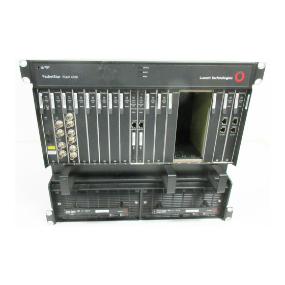
PSAX 4500 Multiservice Media Gateway system hardware. System Features The PacketStar PSAX 4500 Multiservice Media Gateway is a carrier-grade, high-density asynchronous transfer mode (ATM) wide area network (WAN) access concentrator providing network access for TDM voice, frame relay, and ATM data applications. The PSAX 4500 system I/O interfaces are... -
Page 42: Chassis Hardware
Chapter 2 Hardware Description Chassis Hardware • Blank faceplate modules—required for empty I/O and server slots FAIL FAIL FAIL FAIL FAIL FAIL FAIL FAIL FAIL FAIL FAIL FAIL FAIL FAIL FAIL FAIL FAIL FAIL FAIL ACTIVE ACTIVE ACTIVE ACTIVE ACTIVE ACTIVE ACTIVE ACTIVE... -
Page 43: Module Slots
Chapter 2 Hardware Description Chassis Hardware E3, and STS-1e modules while continuing to support over 30 legacy PSAX I/O and server modules. The Power Supply and Stratum modules operate in a load-sharing mode, whereas the CPU2 modules operate in an active/standby mode. All modules are hot swappable. -
Page 44: Power Supply Modules
Chapter 2 Hardware Description Chassis Hardware 9–12, and segment 4 includes slots 13–17. The midplane contains two buses. This feature allows the use of high-performance, broadband modules throughout the chassis. When doing bandwidth calculations for a fully redundant architecture, assume that only one Stratum module is active and uses a bandwidth of 1.2 Gbps per segment. -
Page 45: Stratum Modules
Chapter 2 Hardware Description Chassis Hardware Three LED indicators on the faceplate provide status indications of the module. Refer to the PSAX 4500 Installation Guide for additional information. Figure 2-3. PSAX 4500 Power Supply Module Stratum Modules The PSAX 4500 Stratum module provides the following features: •... -
Page 46: Timing Control
Chapter 2 Hardware Description Chassis Hardware Table 2-1. PSAX Stratum 3–4 Module Status LED Indicators Color Status Description FAIL Indicates the Stratum 3–4 module is not functioning. ACTIVE Green Indicates the Stratum 3–4 module is functioning properly. NO SYNC Yellow Indicates the Stratum 3–4 module is not locked to a reference signal. -
Page 47: System Control And Monitoring
Chapter 2 Hardware Description Chassis Hardware • Composite clock with reference sources meeting ANSI T1.101 and ITU-T G.703 standards • BITS clock meeting Bellcore GR-518-CORE (DS1) and ITU-T G.812 (E1) standards The Line Timing mode synchronizes to any PSAX 4500 port with a terminated synchronous source, while not effecting the traffic on the port. -
Page 48: Midplane Switching
Chapter 2 Hardware Description Chassis Hardware ~ Failure of both Stratum modules ~ Failure of both fans (exception - system shutdown) The following information is reported through the craft, Telnet, or EMS: • Stratum Mode (normal, holdover, or free-run) • Timing Mode (external, internal, or line timing) •... -
Page 49: System Redundancy
Chapter 2 Hardware Description Chassis Hardware Slots 9-12 Stratum Module A Slots 1-4 Segment 1 Segment 3 600 Mbps 600 Mbps Single ATM Bus Single ATM Scalable to Bus Scalable to 1.2 Gbps 1.2 Gbps Slots 13-17 Slots 5-8 Bidirectional 325 Mbs Bidirectional 325 Mbs Segment 2 Segment 4... -
Page 50: Cpu2 Modules
Chapter 2 Hardware Description Optimizing Module Placement CPU2 Modules Operating in a nonload-sharing, active/standby mode, the PSAX CPU2 module provides the processing, switching, and storage functions for the PSAX 4500 system. With a RISC-based microprocessor, the PSAX CPU2 module has the processing power to maintain data flow, perform numerical calculations, and manage the direct memory access (DMA) interfaces. - Page 51 Chapter 2 Hardware Description Optimizing Module Placement Table 2-2. PSAX 4500 Midplane Slot Structure is composed of and can accommodate these This Segment… these slots… types of modules… Segment 1 1–4 High- and Low-speed Segment 2 5–8 High- and Low-speed Segment 3 9–12 High- and Low-speed...
- Page 52 Chapter 2 Hardware Description Optimizing Module Placement Table 2-3. Chassis Speed, Power Consumption, and Memory Allocation Specifications Maximum Total Module Input Chassis Amount of Program and Output Power Con- Module SDRAM Data Space Buffer Buffer Speed sumption DS1/T1 Interface Modules 16–64 MB 8 MB 1 MB...
- Page 53 Chapter 2 Hardware Description Optimizing Module Placement Table 2-3. Chassis Speed, Power Consumption, and Memory Allocation Specifications Maximum Total Module Input Chassis Amount of Program and Output Power Con- Module SDRAM Data Space Buffer Buffer Speed sumption 8–64 MB 3 MB 1 MB Total 15 W...
- Page 54 Chapter 2 Hardware Description Optimizing Module Placement Table 2-3. Chassis Speed, Power Consumption, and Memory Allocation Specifications Maximum Total Module Input Chassis Amount of Program and Output Power Con- Module SDRAM Data Space Buffer Buffer Speed sumption 1-Port OC-3c 1+1 APS 32 MB 8 MB 12 MB...
- Page 55 Chapter 2 Hardware Description Optimizing Module Placement Table 2-3. Chassis Speed, Power Consumption, and Memory Allocation Specifications Maximum Total Module Input Chassis Amount of Program and Output Power Con- Module SDRAM Data Space Buffer Buffer Speed sumption 4-Port Voice 2-Wire 8 MB 4 MB 14 W...
- Page 56 Chapter 2 Hardware Description Optimizing Module Placement This column relates only to the performance of the module in the PSAX 4500 chassis. All modules operate in a low- speed mode in all other PSAX chassis. The speed relates to the performance of the data being passed through the midplane of the chassis.
-
Page 57: System Features
• An advanced queuing and cell-switching algorithm, provided by the AQueMan (adaptive queue management) firmware algorithm, a patented technology offered by Lucent Technologies to differentiate voice, video, and data requirements, thus helping to ensure QoS levels • A cell-counting capability to allow ATM usage-based billing •... - Page 58 Chapter 3 System Features System Capabilites Through the use of the API, the gateway and the PSAX 4500 can combine to perform powerful interworking among ATM, Integrated Services Digital Network (ISDN), Signaling System 7 (SS7), channel associated signaling (CAS), and other protocols •...
-
Page 59: Interface Architecture
Chapter 3 System Features Interface Architecture Interface Architecture The PSAX 4500 interface architecture distinctly separates the ATM adaptation functions from the switching functions of the Multiservice Media Gateway system. The interface architecture has four distinct processes: • Physical media access •... -
Page 60: Spvc Support For Ces
Chapter 3 System Features User Interfaces allow service providers to switch time-division multiplexing (TDM) traffic across the ATM network at individual subscriber levels; that is, each DS0 can be assigned a separate virtual path identifier (VPI) or virtual channel identifier (VCI). This service transports ABCD signaling bits based on the ATM Forum standard for G.704 CAS. -
Page 61: Ds1 Service
Chapter 3 System Features User Interfaces channels. When channels are not being used for voice traffic, the available bandwidth can be used for LAN UBR-class traffic. DS1 Service With the channelized DS1 interface, service providers can concentrate and adapt voice, video, and data traffic to an ATM network. The DS1 interface can adapt any number of DS0 channels on the service access interface to ATM virtual channels with individual virtual path identifiers (VPIs) and virtual channel identifiers (VCIs). -
Page 62: Hdlc Passthrough Bit Inversion
Chapter 3 System Features User Interfaces so errors are unlikely to occur. The following PSAX I/O modules support the HDLC passthrough interface: • 6-Port Enhanced DS1/T1 Multiservice module • 12-Port Medium-Density DS1 Multiservice module • 6-Port Enhanced E1 Multiservice module •... - Page 63 Chapter 3 System Features User Interfaces When a failure condition is detected on a primary interface, the feature moves all affected connections from the primary interface to a standby interface. The standby interface is selected from those available in the interface protection group based on criteria selected by the user.
-
Page 64: Internet Protocol (Ip) Forwarding
Chapter 3 System Features User Interfaces • Switchover methods are Automatic, where traffic from a primary interface is automatically switched to an available standby interface, and Manual, where traffic from a failed primary interface is only switched to the available standby interface when the User selects the switchover. •... -
Page 65: Interim Interswitch Signaling Protocol (Iisp) Interface
Chapter 3 System Features User Interfaces IP=209.252.246.193 OC12c ATM OC3c ATM Lucent PSAX Lucent GX550 Lucent NX 64000 Core Node T1 ATM / N x T1 IMA / or DS3 ATM IP=209.252.246.193 100 BT 100 BT Fast Iron Lucent PSAX Workgroup 10BT Ethernet... -
Page 66: Private Network-Network Interface (Pnni) 1.0
Chapter 3 System Features User Interfaces Private Network-Network Interface (PNNI) 1.0 Overview The Private Network-to-Network Interface, known as PNNI, is a link-state routing information protocol that enables extremely scalable, full function, dynamic multivendor ATM switches to be integrated in the same network. It computes paths through a network by defining a method for distributing topology information between switches and clusters of switches. -
Page 67: Pnni Peer Group Dynamics
Chapter 3 System Features User Interfaces PNNI Peer Group PNNI performs these functions: Dynamics • Simplifies the configuration of large networks because it allows ATM switches to automatically learn about their neighbors and to distribute call routing information dynamically. • Allows switches to be arranged in a hierarchy, where each level represents one or more switches. -
Page 68: Atm Maintenance
Chapter 3 System Features User Interfaces In networks that use a PNNI hierarchy, the switches at each level elect one switch as a peer group leader (PGL). This PGL concurrently belongs to its own level and to the next highest level, where it acts as a logical group node (LGN) that represents and summarizes topology information needed to reach any of the lower-level switches. -
Page 69: Integrated Link Management Interface (Ilmi)
Chapter 3 System Features User Interfaces Integrated Link Management Interface (ILMI) The integrated link management interface (ILMI) is a network management function that supports bidirectional exchange of ATM interface parameters between two connected ATM Interface Management Entities (IMEs). These entities are an end user and a public or private network, or a public network and a private network. -
Page 70: Atm Terminal Emulation
Chapter 3 System Features Network Management parameters for both IISP and PNNI routing. Load balancing between PNNI and IISP links, not available prior to this release, uses available bandwidth more efficiently while strengthening the routing function. ATM Terminal Emulation Terminal Emulation is an application that follows an intelligent computing device to mimic the operation of a dumb terminal for communications with a mainframe or minicomputer. - Page 71 Chapter 3 System Features Network Management features a Simple Network Management Protocol (SNMP)-compliant management information base (MIB) that gives external management systems access to the Multiservice Media Gateway system software. In conjunction with the visual indicators displayed on the front panels of the individual modules, the system offers a full complement of SNMP trap messages that alert the user to faults in the PSAX 4500 system.
-
Page 72: Aqueview
Chapter 3 System Features Network Management host) running an SNMP client over an ATM WAN. This allows for IP- based functions (that is, telnet) and SNMP functions (that is, element and network management software) to be performed remotely using ATM virtual circuits, which terminate within the managed node. The PVC/SVC connection is set up using an I/O module with an ATM cell bearing port (for example, the OC-3c, STM-1, DS1, DS3, E1, and E3 modules). -
Page 73: Psax 4500 System Software Features
Chapter 3 System Features PSAX 4500 System Software Features The AQueView R5.0 system software supports PSAX system software Releases 6.3.0, 6.5.0, and 7.0.0 for the PSAX 4500, PSAX 2300, PSAX 1250, PSAX 20, AC 60 Multiservice Media Gateways. PSAX 4500 System Software Features The Multiservice Media Gateway system software uses permanent virtual circuits (PVCs) and switched virtual circuits (SVCs) to provide end-to-end connectivity for transmission over a network. -
Page 74: Operation
Chapter 3 System Features PSAX 4500 System Software Features links to be used as the primary link for certain DHPVCs while they are used simultaneously as the standby for other DHPVCs. Operation As the DHPVC is established, both the primary and standby circuits are provisioned from the originating node to the terminating node, through the ATM network. -
Page 75: The Aqueman Algorithm
Chapter 3 System Features PSAX 4500 System Software Features ATM Network Link failure Interrupted Multiservice Multiservice service Media Media Gateway Gateway Primary PVC Primary PVC Standby PVC Continued Standby PVC service Figure 3-3. Automatic Rerouting With Dual-Homed PVCs If zero errors are detected by the PSAX 4500 system for a user-selectable interval of 10 seconds, 30 seconds, 1 minute, or 5 minutes (or not allowed), the system restores the primary link. - Page 76 Chapter 3 System Features PSAX 4500 System Software Features As Table 3-1 indicates, variable bit rate (VBR) traffic types (for example, network management data traffic) have a higher priority than some constant bit rate (CBR) traffic (for example, off-peak cellular voice calls). The AQueMan algorithm accounts for the service-level priorities of the traffic when determining which cells to discard during traffic congestion.
- Page 77 Chapter 3 System Features PSAX 4500 System Software Features Table 3-2 details the Multiservice Media Gateway system support of defined ATM quality of service (QoS) classes. Table 3-2. Multiservice Media Gateway System-Supported Service Classes ATM Service Class Description Constant Bit Rate (CBR) This service operates on a connection basis and offers consistent delay predictability.
- Page 78 Chapter 3 System Features PSAX 4500 System Software Features Table 3-3. Class of Service Descriptions Variable Bit Rate Real Variable Bit Constant Bit Time Rate Non-real Unspecified Bit Rate (CBR) (VBR-RT) Time (VBR-NRT) Rate (UBR) Service Private line Com- Frame relay, Raw cell, Examples pressed...
- Page 79 Chapter 3 System Features PSAX 4500 System Software Features Table 3-5. Mapping ATM Service Classes to Multiservice Media Gateway System Priority Levels PVC Connection ATM Classes of Internal Configuration Service Priority Selections Service Examples Constant Bit CBR-1 CBR1 911 calls Rate (CBR) CBR-2 CBR2...
-
Page 80: Connection Gateway Api
Chapter 3 System Features PSAX 4500 System Software Features priority VBR buffers. The execution of this algorithm is based on the priority levels the user selects. • Cell aging This capability prevents the lowest-priority data (for example, IP data) from being buffered in the Multiservice Media Gateway systems indefinitely. -
Page 81: Firmware Release Control
"Upgrading and Backing Up System Software and Firmware" chapter, should be used only on the advice of Lucent Technologies NetworkCare personnel (see the "Technical Support" section in Chapter 1, "Getting Started."). The Multiservice Media Gateway CPU has access to the firmware binaries of all modules present in the Multiservice Media Gateway mainframe. - Page 82 Chapter 3 System Features PSAX 4500 System Software Features conjunction with the LANET protocol, which helps maintain cell-delineation capability up to a random 10 bit error rate (BER) with 0.625 percent bandwidth overhead, maximum protection is obtained. Multiple redundancy addressing sets up multiple virtual circuits to the same destination.
-
Page 83: Frame Relay-To-Atm Interworking
Chapter 3 System Features PSAX 4500 System Software Features Table 3-7. Rate Options Bit Error Rate Cell Encoding Threshold Threshold Threshold Rate Automatic—low quality 1/2 rate 1/4 rate 1/8 rate Automatic 1/2 rate 1/2 rate 1/8 rate Automatic—high quality 1/2 rate 1/2 rate 1/4 rate When the user selects the 1/2, the 1/4, or the 1/8 rate, the encoder maintains... -
Page 84: Frame Relay-To-Frame Relay Interworking
Lucent Stinger DSLAM, a CellPipe IAD, and a central office voice switch, such as the Lucent Technologies 5ESS switch, or with Nortel’s DMS switch. The GR-303 interface protocol is available on the PacketStar 6-Port Enhanced DS1/T1 Multiservice, the 1-Port Channelized DS3 Multiservice, and the 1-Port Channelized STS-1e, T1 Format I/O modules, and works in conjunction with the DSP2C Voice Server module’s voice processing... -
Page 85: Inverse Multiplexing Over Atm (Ima)
Chapter 3 System Features PSAX 4500 System Software Features allowing multiple interface groups to simultaneously interface with a large number of switches. BRI ISDN is not supported. Loop emulation services provide multiplexed AAL2 PVC support for the PacketStar ® PSAX Multiservice Media Gateway central office product line. Loop emulation services allow voice traffic, DTMF, and signaling to be handled over the packet network. - Page 86 Chapter 3 System Features PSAX 4500 System Software Features The LANET solution offers link quality-dependent header protection while maintaining maximum compatibility with ATM standards. Figure 3-4 shows the relationship between LANET and the Open Systems Interconnection (OSI) model. SERVICE-INDEPENDENT ARCHITECTURE Voice Video Images...
- Page 87 Chapter 3 System Features PSAX 4500 System Software Features multiple virtual circuits to the same destination, requiring no special hardware nor modification to the current standard. The addresses for the circuits are within the error space of the principal address used for actual transmission.
-
Page 88: Operations, Administration, And Maintenance (Oam)
Chapter 3 System Features PSAX 4500 System Software Features Operations, Administration, and Maintenance (OAM) Overview The Operations, Administration, and Maintenance (OAM) feature, available ® on all PacketStar Multiservice Media Gateway systems gives Public Service Providers a way to detect and receive reports on abnormal behavior in virtual path connections (VPCs) and virtual channel connections (VCCs) in an ATM network. -
Page 89: Oam Atm Layer Flows
Chapter 3 System Features PSAX 4500 System Software Features The format of an OAM cell is shown in Figure 3-6: Header Payload OAM Function Type Reserved Header 360 bits (45 bytes) Function-specific field Error Cell Detectio Type Code Figure 3-6. OAM Cell Fields •... -
Page 90: Oam F4 Cells
Chapter 3 System Features PSAX 4500 System Software Features Figure 3-7. OAM Hierarchy OAM F4 Cells F4 in-band maintenance flows are defined at the ATM layer for the VPC level. It is used for path level connections, where the virtual path (VP) flows are identified by reserved values within the path. -
Page 91: Atm Layer Oam Functions
Chapter 3 System Features PSAX 4500 System Software Features • The same VPI/VCI values as the user cells for the VCC • Identification by one or more preassigned VCIs for both directions • Existence in the same physical route for fault correlation and performance information User cells at the F5 level carry VCI cells which are defined below: PTI=4 is a segment OAM F5 flow cell. - Page 92 Chapter 3 System Features PSAX 4500 System Software Features seconds, the loopback is considered successful. If the source does not receive a successful loopback, it declares a time out. The following types of loopback are supported: • End-to-end: Sends cells from one designated end-point to another. •...
-
Page 93: Soft Permanent Virtual Circuits (Spvcs)
Chapter 3 System Features Soft Permanent Virtual Circuits (SPVCs) PM Block Size (A-B, B-A) is a feature that works with activation requests only. It monitors the size of user cell blocks that monitor the performance in the forward or backward direction. (The default is 1,024 cells.) Soft Permanent Virtual Circuits (SPVCs) The soft permanent virtual circuit (SPVC) feature is a semipermanent virtual circuit enabled by management action. -
Page 94: Svc Functional Description
Chapter 3 System Features Switched Virtual Circuits • The maximum individual call setup time is 16 milliseconds (ms). The minimum call setup time for SVCs is approximately 10 ms from the time the call setup message enters the CPU module until the acknowledgment leaves the CPU module. - Page 95 Chapter 3 System Features Switched Virtual Circuits Both user-side and network-side interfaces undergo similar state transitions. Transition messages trigger these call-state changes as follows: Call States Description #0—Null No call exists. #1—Call initiated • User—The user has requested that the system establish an outgoing call on the network.
- Page 96 Chapter 3 System Features Switched Virtual Circuits Call States Description #10—Active • User—For incoming calls, when the user has been awarded the call. For outgoing calls, when the user has received an indication that the remote user has answered the call. •...
-
Page 97: Traffic Management (Upc Support)
Chapter 3 System Features Traffic Management (UPC Support) Traffic Management (UPC Support) Release 6.3.0 implemented Phase 2 of a multiphase development program to provide ingress ATM policing on ATM interfaces. Over several development phases, Lucent will add new service classes and expand feature coverage on ATM interface modules. - Page 98 Chapter 3 System Features Traffic Shaping Network Switch Switch Bursty LAN ATM Traffic Bursty LAN ATM Traffic OC-3c OC-3c Shaped Traffic to Comply with PacketStar PacketStar ATM Service Contract Multiservice Media Gateway Multiservice Media Gateway Figure 3-9. Traffic-Shaping Application An end user has an ATM DS3 network connection and has subscribed to a VBR VCC connection contract from a carrier (service provider) with the following traffic parameters: 1) sustained cell rate (SCR) is 40,000 cells/second;...
- Page 99 Chapter 3 System Features Traffic Shaping The input cell-selection buffering scheme is shown in Figure 3-10. Line Rate Greater Than 250 Cells MBS of Each VPC/VCC Sample Input on a VPC/VCC Connection Usually Connection from a Bursty LAN Less Than 50 Cells VPC/VCC 1 S C R Input Enters...
-
Page 100: Rate Shaping
Chapter 3 System Features Traffic Shaping The algorithm processes traffic moving out of the input cell selection buffer according to the SCR of the particular VPC/VCC. The MBSs of traffic-shaped output are set as follows: Sustained Cell Rate Maximum Burst Size (MBS) of Traffic- (SCR) of VPC/VCC Shaped Output 0–20 Mbits/sec. -
Page 101: Configuring Rate Shaping For Hdlc, Frame Relay, And Ethernet Virtual Channels
Chapter 3 System Features Traffic Shaping Configuring Rate Shaping for HDLC, Frame Relay, and Ethernet Virtual Channels To configure the rate shaping feature, the traffic shaping feature must be enabled on the ATM UNI 3.1, ATM PNNI, or ATM IISP interface configuration windows of the OC-3c 1+1 APS or the STM-1 1+1 MSP modules. -
Page 102: Rate Shaping For Cbr And Vbr-Rt
Chapter 3 System Features Traffic Shaping greater than its SCR. Include in your calculation the function (F) in the formula (see the section titled ”Formula for Determining the PCR of a Rate Shaped Connection” below for the total CBR and VBR-rt traffic provisioned for the interface (see the earlier section ”VBR Rate Shaping Priorities”). - Page 103 Chapter 3 System Features Traffic Shaping is 386, it will send one cell from queue 386. If the offset time value T is 20, the rate shaper moves queue number 386 to box 21 (box 1 + T value 20), providing the timing for the next time queue 386 will be visited.
-
Page 104: Virtual Interfaces
Chapter 3 System Features Virtual Interfaces 11. The rate shaper transfers queue 6 into box 53 on the Rate Shaping table to the bottom of the queue stack in box 53. 12. The rate shaper progresses to box 4 of the rate shaping table and repeats Steps 1 through 3 and cycles through all 80,000 cells over and over, using this algorithm. - Page 105 Chapter 3 System Features Virtual Interfaces queue. By using VIs instead of physical connections, it is possible to achieve advanced bandwidth management capability allowing for fully flexible service provisioning. Working in conjunction with AQueMan software and Usage Parameter Control (UPC), VIs give service providers a way to maximize revenue by oversubscribing their bandwidth without violating their QoS agreements.
- Page 106 Chapter 3 System Features Virtual Interfaces Note: Each virtual interface supports UPC; however, it is not possible to designate UPC for individual virtual paths and virtual connections within a virtual interface. Bursts of VBR traffic that exceed the available bandwidth are buffered and serviced in accordance with the AQueMan buffering algorithm.
- Page 107 Chapter 3 System Features Virtual Interfaces 10 Class of Service Queues CBR-1 CBR-2 CBR-3 CBR-4 AQueMan VBR-EX Queuing Algorithm VBR-RT1 VBR-RT2 VBR-NRT1 VBR-NRT2 CBR-1 CBR-2 CBR-3 CBR-4 AQueMan Physical VBR-EX Queuing VI Scheduler Connection Algorithm VBR-RT1 VBR-RT2 VBR-NRT1 VBR-NRT2 CBR-1 VI = 1 PVP with multiple PVCs CBR-2...
- Page 108 Chapter 3 System Features Virtual Interfaces remaining non-VI traffic can burst up to 45 Mbps. This provides a natural separation between guaranteed versus nonguaranteed traffic. UPC parameters can be involved at the ingress, allowing the service provider to not only control the ingress traffic but to also ensure that the bandwidth throughout the network does not violate the SLA.
-
Page 109: Voice Compression
Chapter 3 System Features Voice Compression UNI 4.0 Signaling, af-sig-0061 Traffic Management, af-tm-0056 Voice Compression A noncompressed voice channel uses 64 Kbps of bandwidth. Voice compression reduces the 64 Kbps bandwidth to a lower value, based on the algorithm chosen. Compressed voice messages can be carried over ATM Adaptation Layer 2 (AAL2) only. -
Page 110: I/O And Server Modules
Chapter 3 System Features I/O and Server Modules Figure 3-16 illustrates how an Multiservice Media Gateway using voice processing might be deployed in a combined voice/data network. Voice Voice Network Network Network Uncompressed Uncompressed Voice Voice Access Access Network Compressed Compressed Concentrator Concentrato... - Page 111 Chapter 3 System Features I/O and Server Modules 1-Port DS3 IMA ( DS3 IMA 1-Port Unchannelized DS3 Frame Relay ( DS3 FR 2-Port DS3 ATM ( DS3 ATM 2-Port E3 ATM ( E3 ATM 3-Port Channelized DS3/STS-1e CES ( CH DS3/STS-1E 3-Port Unstructured DS3/E3 CES ( UNSTR DS3/E3 CES 1-Port Channelized STS-1e, T1 Format (...
-
Page 112: 1-Port Channelized Ds3 Module
Chapter 3 System Features 1-Port Channelized DS3 Module 1-Port Channelized DS3 Module The 1-Port Channelized DS3 Multiservice module provides one port with a line rate of 44.736 Mbps. The user can configure this module to provide N x 64 Kbps (fractional DS1) structured circuit emulation service. When configured for DS1 circuit-emulation service, the module interfaces with TDM channelized DS1 circuits. -
Page 113: Hardware Features
Chapter 3 System Features 1-Port Channelized DS3/STS-1e CES Module • AAL2 cell formatting is provided for interworking with the DSP2A, DSP2B, and DSP2C Voice Server modules. • Mixed circuit emulation, ATM, and frame relay channels can be configured within a virtual DS1 port. Hardware Features The Channelized DS3 module has the following hardware features: •... -
Page 114: Hardware Features
Chapter 3 System Features 1-Port Channelized DS3/STS-1e CES Module ISDN primary rate interface (PRI) service. Because this structured circuit- emulation service can be configured to use only a fraction of the time slots, several independent emulated circuits can be configured to share one service interface. -
Page 115: 1-Port Channelized Sts-1E T1 Module
Chapter 3 System Features 1-Port Channelized STS-1e T1 Module • 44.736 DS3 Mbps Physical Layer Specification, af-uni-0010.002 • DS3 Physical Interface Specification, af-phy-0054 1-Port Channelized STS-1e T1 Module The 1-Port Channelized STS-1e, T1 format module provides one port with a line rate of 51.84 Mbps. -
Page 116: Hardware Features
Chapter 3 System Features 6-Port DS1 IMA Module ~ Traffic policing Hardware Features • Number of ports: one • Connector type: two BNC connectors, one to receive data and the other to transmit data • Line rate: 51.84 Mbps 6-Port DS1 IMA Module The 6-Port DS1 IMA module has six physical RJ-45 ports. -
Page 117: 2-Port Ds3 Atm Module
Chapter 3 System Features 2-Port DS3 ATM Module • Framing mode: cyclic redundancy check multifrequency (CRC-mf) 2-Port DS3 ATM Module The 2-Port DS3 ATM provides a network interface at Digital Signal Level 3 (DS3), with a line rate of 44.736 Mbps. Typically, this module is used to connect the PSAX system to an ATM edge switch or digital subscriber line aggregation multiplexer (DSLAM) device. -
Page 118: Hardware Features
Chapter 3 System Features 1-Port DS3 IMA Module ~ Congestion management ~ Traffic policing ~ HDLC pass-through Frame Relay The 1-Port Unchannelized DS3 Frame Relay module has interfaces for frame- relay network-level interworking (FRF.5) and service-level interworking (FRF.8). A maximum of 350 permanent virtual circuits (PVCs) can be assigned on each frame relay user-network interface (UNI) port. -
Page 119: Software Features
Chapter 3 System Features 6-Port E1 IMA Module ® Port DS1 IMA module (see the PacketStar 6-Port DS1 IMA Module User Guide). It allows you to configure up to 28 virtual T1 ports for native DS1 ATM services or for as many as 14 independent groups. This gives you point-to- point bandwidth options between that of a single T1 line and that of a T3 line. -
Page 120: Software Features
Chapter 3 System Features 2-Port E3 ATM Module Software Features The 6-Port E1 IMA module offers native E1 ATM services and E1 IMA services, including permanent virtual circuits, soft permanent virtual circuits, and switched virtual circuits. The module supports UNI v3.a, IISP, PNNI, and ILMI. -
Page 121: 6-Port Enhanced Ds1 Module
Chapter 3 System Features 6-Port Enhanced DS1 Module • Loopback capabilities: local loop, line loop, payload loop • Cell mapping: direct mapping 6-Port Enhanced DS1 Module The 6-Port Enhanced DS1/T1 Multiservice module provides six ports, each with a line rate of 1.544 Mbps. The interfaces support American National Standards Institute (ANSI) T1.403, af-phy-0016.000 and af-test-0037.000. -
Page 122: Hardware Features
Chapter 3 System Features 6-Port Enhanced E1 Module • CE: Circuit emulation service (CES) with ISDN PRI using 64 Kbps clear channel; dynamic bandwidth circuit emulation service (DBCES—proprietary version); 1 X 56 Kbps structured CAS; unstructured CES • HDLC Passthrough •... -
Page 123: Software Features
Chapter 3 System Features 6-Port Enhanced E1 Module channels per port to ATM virtual channels with individual virtual path identifiers (VPIs) and virtual channel identifiers (VCIs), using structured (channelized) circuit emulation. Signaling bit transport from time slot 16 is also provided, based on ATM Forum standards for channel-associated signaling (CAS). -
Page 124: Ethernet Module
Chapter 3 System Features Ethernet Module Ethernet Module The Ethernet module provides five ports on the faceplate and a sixth virtual port. The first of these ports has the ability to autosense and operate at either 100baseT or 10baseT. The remaining four ports operate at 10baseT. Each of the ports can be configured independently to operate within shared or separate bridge groups. -
Page 125: Hardware Features
Chapter 3 System Features 21-Port High-Density E1 Module • The IP forwarding feature is not to be confused with the kind of routing capability that supports virtual channel multiplexed routed packets or link layer control-subnetwork access protocol (LLC-SNAP).Do not apply the Routing interface type to Ethernet virtual channels. -
Page 126: Software Features
Chapter 3 System Features 21-Port High-Density E1 Module service, and ATM service. This module has two types of light-emitting diode (LED) indicators: FAIL and ACTIVE. Configured for channelized E1 service, the 21-Port High-Density E1 Multiservice module maps up to 31 individual high level data links (HDLC) on a single E1 connection (180 HDLC data links per module). -
Page 127: Hardware Features
Chapter 3 System Features 12-Port Medium-Density DS1 Module Hardware Features The 21-Port High-Density E1 Multiservice module provides the following hardware features: • Number of ports: 21 • Connector type: two Mini-Champ connectors that mate with the AMP cable #1324936-1 • Line rate: 2.048 Mbps •... -
Page 128: Software Features
Chapter 3 System Features 6-Port Multiserial Module Software Features The 12-Port Medium-Density DS1 Multiservice module supports the following services: • ATM: ATM UNI 3.0 and 3.1; Interim inter-switch signaling protocol (IISP) user, IISP network • CE: Circuit emulation service (CES) with ISDN PRI using 64 Kbps clear channel;... -
Page 129: Interfaces
Chapter 3 System Features 6-Port Multiserial Module the T1 is filled with 56 Kbps of SS7 data and 8 Kbps of overhead (stuffing) data. The SS7 circuits originating from the Multiserial interface can be mapped using AAL1 to an individual ATM constant bit rate (CBR) class of service exiting on a DS3 ATM cell-bearing interface. -
Page 130: Circuit Emulation
Chapter 3 System Features 6-Port Multiserial Module Information Rate (CIR), Excess Burst size (Be), and Committed Burst size (Bc). Circuit Emulation Each port on the 6-Port Multiserial module can be configured to perform adaptation for circuit emulation. The implementation of ATM Adaptation Layer 1 (AAL-1) allows for the transmission of circuit emulation data as Constant Bit Rate (CBR) traffic across an ATM network. -
Page 131: Quadserial Module
Chapter 3 System Features Quadserial Module • Connector type: micro-DB15 • Physical interfaces supported: EIA-232-D, EIA-530, EIA-449 v.11 (subset), and V.35, with the Multiservice Media Gateway system configured as either a data terminating equipment (DTE) or a data communications equipment (DCE) device. •... -
Page 132: Software Features
Chapter 3 System Features 3-Port Unstructured DS3/E3 CES Module Software Features The Quadserial module supports the following services: • ATM: ATM UNI 3.0 and 3.1; Interim inter-switch signaling protocol (IISP) user, IISP network; PNNI user, PNNI network • CE: Circuit emulation service (CES) with AAL1 adaptive clocking •... -
Page 133: Software Features
Chapter 3 System Features 1-Port OC-12c/STM-4c 1+1 APS/MSP Multimode and Single-Mode Modules American and international ATM networks from a single module. The 3-Port Unstructured DS3/E3 CES module has three types of LED indicators: FAIL, ACTIVE, and LOS (loss of signal). Software Features Each port on the 3-Port Unstructured DS3/E3 CES module can be configured to perform adaptation for circuit emulation. -
Page 134: Hardware Features
Chapter 3 System Features 1-Port OC-12c/STM-4c 1+1 APS/MSP Multimode and Single-Mode Modules The 1+1 protection implementation is compliant with the GR-253-CORE standard and supports linear non-revertive 1+1 protection, in both bidirectional and unidirectional modes. Two versions of the OC-12c/STM-4c module are offered to support different applications: •... -
Page 135: 1-Port Oc-3C Multimode And Single-Mode Modules
Chapter 3 System Features 1-Port OC-3c Multimode and Single-Mode Modules Table 3-8. OC-12c/STM-4c 1+1 APS/MSP Multimode and Single-Mode Modules Hardware Specifications OC-12c/STM-4c Modules Feature Single-Mode Multimode Optical output power -11 dBm -17 dBm System gain Transmitter minimum opti- -15 dBm -20 dBm cal output power Transmitter maximum opti-... -
Page 136: Hardware Features
Chapter 3 System Features 1-Port OC-3c Multimode and Single-Mode 1+1 APS Modules Hardware Features The1-Port OC-3c Multimode and Single-Mode modules have the hardware specifications shown in Table 3-9: Table 3-9. OC-3c Multimode and Single-Mode Hardware Specifications Module Feature OC-3c SM OC-3c MM Number of ports Type of connector (two for each... -
Page 137: Software Features
Chapter 3 System Features 1-Port OC-3c Multimode and Single-Mode 1+1 APS Modules • The OC-3c Multimode (MM) 1+1 APS module is intended for short-reach applications, for example, interoffice or intraoffice sections of a local area network (LAN) within a radius of 1.93 km (1.2 miles). Software Features The 1-Port OC-3c 1+1 APS MM and SM modules use the AQueMan algorithm for traffic flow control. -
Page 138: 1-Port Stm-1 Multimode And Single-Mode Modules
Chapter 3 System Features 1-Port STM-1 Multimode and Single-Mode Modules Table 3-10. OC-3c Multimode and Single-Mode Hardware Specifications Module Feature OC-3c SM OC-3c MM Transmitter maximum opti- -8 dBm -14 dBm cal output power (average) Receiver minimum optical -31 dBm -32.5 dBm input power (average) Receiver maximum optical... -
Page 139: Hardware Features
Chapter 3 System Features 1-Port STM-1 1+1 MSP Multimode and Single-Mode Modules • Variable bit rate (VBR): VBR real time level 1 (VBR-RT1), VBR real time level 2 (VBR-RT2), VBR non-real time level 1 (VBR-NRT1), VBR non-real time level 2 (VBR-NRT2), VBR-express •... -
Page 140: Dsp2X Voice Server Modules
Chapter 3 System Features DSP2x Voice Server Modules Table 3-11. STM-1 Multimode and Single-Mode Hardware Specifications Module Feature STM-1 SM STM-1 MM Fiber-optic cable reach (approxi- 25.7 km 2 km mate, depending on fiber (16 miles) (6,560 feet or 1.2 makeup) miles) Line rate... -
Page 141: Software Features
Chapter 3 System Features DSP2x Voice Server Modules Software Features The DSP2x Voice Server Modules maintain required levels of voice quality while conserving network bandwidth by using digital signal processor technology to compress voice traffic. The four voice processing modes available on the DSP2C voice server module are algorithm sets (algosets) 1 through 4. -
Page 142: Route Server Module
Chapter 3 System Features Route Server Module • The DSP2D module requires System Software Release 7.0.0. Any number of DSP2x Voice Server modules can be supported per chassis, within the allowed System Software Release parameters: • The DSP2A and DSP2B modules require System Software Release 5.0.1 or higher. -
Page 143: Software Features
Chapter 3 System Features Route Server Module You can assign an authentication password to an IP network interface for maximum security. Doing so can prevent those who cannot directly access the network from sending false routing information to the routers. RIP v1.0 messages will be ignored when authentication is in use. -
Page 144: Tones And Announcements Server Module
Chapter 3 System Features Tones and Announcements Server Module Tones and Announcements Server Module The Tones and Announcements Server (TAS) module offers these tests in a switch-to-switch capacity: ~ SS7 (Signaling System 7) continuity test for VToA ~ 1004 Hz (miliwatt) test tone support (Type 102) ~ Digital, non-inverting loopback (Type 108) ~ Automatic Transmisson measurement( Type 105) These tests enable PSAX products to provide tones and signaling testing on... -
Page 145: Configuring The Basic System
Configuring the Basic System Overview of This Chapter This chapter describes how to configure the PSAX 4500 Multiservice Media Gateway system and set the system values for your site. Before you do this, ® be sure you have done the following tasks as described in the PacketStar PSAX 4500 Multiservice Media Gateway Installation Guide: •... - Page 146 Chapter 4 Configuring the Basic System Logging onto the System The PSAX 4500 Logon window is displayed (see Figure 4-1). Figure 4-1. PSAX 4500 Multiservice Media Gateway System Logon Window 3 Enter the appropriate values on this window as described in Table 4-1: Table 4-1.
- Page 147 Chapter 4 Configuring the Basic System Logging onto the System Table 4-1. Field Descriptions for the Logon Window Field Names Values Description Password Default: This value is the intial default for the username readwrite. lucenttech1, Change the password during your first logon session on the User Options win- dow.
-
Page 148: Help Information
Chapter 4 Configuring the Basic System Logging onto the System At the time of initial configuration, the Console Interface Main Menu window is displayed a field with a pair of opposing square brackets in the upper right corner. This field contains the site name, which you enter during site-specific configuration (see the procedure in ”Configuring System Identification”... - Page 149 Chapter 4 Configuring the Basic System Logging onto the System Viewing the Help Windows Begin 1 On the Console Interface Main Menu window, press the ? key. The first Main Menu Help window is displayed (see Figure 4-3): Your site name will appear here after initial configuration Information line...
- Page 150 Chapter 4 Configuring the Basic System Logging onto the System 2 To display the second through fourth Main Menu Help windows (see Figure 4-4 through Figure 4-6), press the Down Arrow. Figure 4-4. Main Menu Help Window 2 Figure 4-5. Main Menu Help Window 3 ®...
-
Page 151: Selecting Options, Fields, And Commands
Chapter 4 Configuring the Basic System Logging onto the System Figure 4-6. Main Menu Help Window 4 Selecting Options, Fields, and Commands As described on the Help windows, follow these steps to select an option, field, or command: 1 Press the Up Arrow or the Down Arrow to highlight (reverse video image) the option name, field name, or command you want to select, and press Enter. -
Page 152: Changing The System Password And Other User Options
Chapter 4 Configuring the Basic System Changing the System Password and Other User Options ~ The information line displays a message indicating an error or successful completion of the command. ~ The system displays the next higher level or previous window (Enter to <window name>... - Page 153 Chapter 4 Configuring the Basic System Changing the System Password and Other User Options The User Options window is displayed (see Figure 4-7). Figure 4-7. User Options Window 2 Select the Change Password For <username> field. a. Type the current password, and press Enter. b.
-
Page 154: Console Interface Main Menu
Chapter 4 Configuring the Basic System Console Interface Main Menu 6 On the Console Interface Main Menu window, select the Save Configuration command, and press Enter to store the values in the PSAX system database. The new values will take effect after the chassis reboots. -
Page 155: System Identification Data
Chapter 4 Configuring the Basic System Configuring the System for Your Site System Identification Configuring System Values for Your Site Data Begin 1 On the Console Interface Main Menu window, select the Site-Specific Configuration command. The Site-Specific Menu window is displayed (see Figure 4-8). Figure 4-8. -
Page 156: Rules For Configuring Ip Addresses
Chapter 4 Configuring the Basic System Configuring the System for Your Site The Site-Specific Configuration window is displayed (see Figure 4-9). Figure 4-9. Site-Specific Configuration Window Note: The system performs error checking on each field by highlighting any field containing an incorrect value. Use the system message displayed in the information line to help you correct any errors. -
Page 157: Rules For Configuring Ip Address Masks
Chapter 4 Configuring the Basic System Configuring the System for Your Site 2. CPU IP and switch IP addresses cannot be the same. 3. CPU IP and switch IP addresses cannot be on the same subnet as the in-band IP address. 4. -
Page 158: Entering And Displaying Atm Addresses And Oam Properties
Chapter 4 Configuring the Basic System Configuring the System for Your Site Entering and Perform the steps in the following procedure to configure the loopback Displaying ATM parameters on modules that support loopback configuration. Addresses and OAM Properties Viewing OAM Properties Begin 1 Select the values for the fields in the Master ATM Address and OAM related data panel as described in Table 4-2. - Page 159 Chapter 4 Configuring the Basic System Configuring the System for Your Site 3 To return to the Console Interface Main Menu window, press Ctrl+B. Entering the System Identification Begin 1 To set the system identification for your site, select the values for the fields on the System Identification panel on the Site-Specific Configuration window as described in Table 4-3.
-
Page 160: Configuring System Date And Time
Chapter 4 Configuring the Basic System Configuring the System for Your Site Table 4-3. Field Descriptions for the System Identification Panel IP Mask Enter the IP mask for ethernet access to your site. (display only) This field determines which part of the IP address is the network identifier, and shows the subnet mask of the network. -
Page 161: Configuring The Tcp Server And Client
Chapter 4 Configuring the Basic System Configuring the TCP Server and Client Table 4-4. Field Descriptions for the System Date and Time Panel Time from UTC Sets local time display by adding or subtracting hours and minutes from the UTC. Note: Both negative and positive hourly time selections are available. - Page 162 Chapter 4 Configuring the Basic System Configuring the TCP Server and Client Ethernet ATM I/O Module Module In-band In-band Local Access Concentrator Management Management (Primary TCP Client) PVC Connection PVC Connection Ethernet Hub Ethernet ATM I/O ATM I/O Call Controller Module Module Module...
-
Page 163: Connection Gateway Application Programming Interface (Api)
Chapter 4 Configuring the Basic System Configuring the TCP Server and Client Connection Gateway API is a protocol that can be used in addition to SNMP to manage the Lucent Application Technologies PSAX systems. It provides an interface to the PSAX system so Programming an external workstation, which is acting as a gateway, can control ATM Interface (API) - Page 164 Chapter 4 Configuring the Basic System Configuring the TCP Server and Client Figure 4-13. TCP Server Configuration Window (PSAX as TCP Server) Commands The commands on this window have the following functions: Command Function • Apply TCP Server Con- Applies the configuration. figuration •...
-
Page 165: Configuring Snmp Trap Destinations
Chapter 4 Configuring the Basic System Configuring the TCP Server and Client Field Descriptions Table 4-5. Field Descriptions for the TCP Server Configuration Window Field Values Description Server IP Varies Enter the IP address of the server, such Address as the call controller. This field is only available for configuration if the PSAX system has been designated as a client. -
Page 166: Configuring In-Band Management
Chapter 4 Configuring the Basic System Configuring In-Band Management Table 4-6. Field Values for the SNMP Trap Destinations Panel Field Value Description Interface (default) Sets the source address used in all SNMP traps to the IP address of the interface from which they are sent Ethernet Sets the source address used in all SNMP traps to... -
Page 167: Adding An In-Band Management Atm Svc Connection
Chapter 4 Configuring the Basic System Configuring In-Band Management Connection” and ”Creating an In-Band-Management SVC Connection” on page 4-24. Adding an In-Band Management ATM SVC Connection A Unix workstation is used as the address resolution protocol (ARP) server. The host PSAX system and all remote systems on the same ATM network register their IP addresses on the ARP server when they are initialized (booted). -
Page 168: Creating An In-Band-Management Svc Connection
Chapter 4 Configuring the Basic System Configuring In-Band Management 3 In the Equipment Configuration window, select the module you will use. The OC-3c module is the most often used I/O module for this connection. 4 Configure the OC-3c module (or the module you have selected) for Interface Type ATMUNI 3.1 and select Apply Port and Channel Configuration. - Page 169 Chapter 4 Configuring the Basic System Configuring In-Band Management Figure 4-15. Site-Specific Menu Window 2 Select the In-band Management option and press Enter. The In-Band Management Configuration Window displays (see Figure 4-16). Figure 4-16. In-Band Management Configuration Window (SVC Disabled) ®...
- Page 170 Chapter 4 Configuring the Basic System Configuring In-Band Management Commands The commands on this window have the following functions: Command Function • Apply Configuration Applies the configuration. • Reset Display Resets the display. • In-Band Mgmt Route Displays the In-Band Mgmt Route Table. Table This button is ghosted if Disabled is selected in the ATM ARP Server field, and...
- Page 171 Chapter 4 Configuring the Basic System Configuring In-Band Management Figure 4-17. In-Band Management Configuration Window (SVC and ARP Enabled) Field Descriptions 5 Select the values for the fields on this window from the values given in Table 4-7. Table 4-7. Field Descriptions for the In-Band Management Configuration Window Field Name Values...
- Page 172 Chapter 4 Configuring the Basic System Configuring In-Band Management Table 4-7. Field Descriptions for the In-Band Management Configuration Window Field Name Values Description Application Enter the application ATM address of ATM Address the Access Concentrator in hexadecimal notation. App. ATM Nsap (default) Select the application ATM address type Address Type...
- Page 173 Chapter 4 Configuring the Basic System Configuring In-Band Management Figure 4-18. Inband Management Route Table Window Note: At the time of initial setup, the In-Band Management Table window is empty. After you have set up routes, this window displays all the routes of this type in the system. Commands The commands on this window have the following functions: Command...
- Page 174 Chapter 4 Configuring the Basic System Configuring In-Band Management Figure 4-19. Inband Management Route Configuration Window 9 Select the Add a route command and press Enter. Commands The commands on this window have the following functions: Command Function • Reset Resets the display.
-
Page 175: Viewing In-Band Statistics Data
Chapter 4 Configuring the Basic System Configuring In-Band Management Table 4-8. Field Descriptions for the In-Band Management Route Configuration Window Field Name Values Description Next Hop IP Address Gateway to the destination network [Route Status] Invalid This route has not been created or is otherwise not valid. - Page 176 Chapter 4 Configuring the Basic System Configuring In-Band Management Figure 4-21. In-Band Management Interface Statistics Window Commands The commands on this window have the following functions: Command Function • Continuous Update Continuously updates the information in the fields every second. Select this com- mand and press Enter to turn the continu- ous updating on and off as needed (similar to a toggle switch).
-
Page 177: Deleting An In-Band Management Svc Route
Chapter 4 Configuring the Basic System PNNI System-Wide Configuration Table 4-9. Field Descriptions for the In-Band Management Statistics Window Field Name Description Packets Transmit- Displays the number of packets transmitted. (display only) Packet Transmit Displays the number of packet transmit errors. Errors (display only) Deleting an In-Band... - Page 178 Chapter 4 Configuring the Basic System PNNI System-Wide Configuration Figure 4-22. PNNI System-Wide Configuration Window Commands The commands in this window have the following functions: Command Function • PNNI Node Configures the PNNI Node. Configuration • PNNI Route Address Con- Adds the route address.
- Page 179 Chapter 4 Configuring the Basic System PNNI System-Wide Configuration Command Function • PNNI Link Information Displays an index of nodes and their associ- ated links for this PSAX 4500 system. • [PNNI SVCC RCC Infor- Not currently supported. mation] • PNNI Neighbor Peer Displays nodes that are on the same level as Information this node.
- Page 180 Chapter 4 Configuring the Basic System PNNI System-Wide Configuration Command Function • Page Up Scroll up one page. • Page Down Scrolls down one page. • Top Displays entries at the top of the table. • Bottom Displays entries at the bottom of the table. •...
- Page 181 Chapter 4 Configuring the Basic System PNNI System-Wide Configuration Figure 4-24. PNNI Node Configuration Window Commands The commands on this window have the following functions: Command Function • Create Node Entry Create a new PNNI node. • Delete Node Entry Delete an existing PNNI node.
- Page 182 Chapter 4 Configuring the Basic System PNNI System-Wide Configuration Table 4-11. Field Values for the PNNI Node Configuration Window Field Name Values Description Node Index 00000 (default); The node index identifies a logical PNNI entity in the PSAX system. Range: Enter 1 in this field.
- Page 183 Chapter 4 Configuring the Basic System PNNI System-Wide Configuration Table 4-11. Field Values for the PNNI Node Configuration Window Field Name Values Description Res. Transit False (default), Restricted transit indicates whether the True node is restricted to not allowing sup- port of SVCs transmitting from this node.
-
Page 184: Configuring Pnni Route Addresses
Chapter 4 Configuring the Basic System PNNI System-Wide Configuration The OperStatus display field indicates that the node is up. Note: You must bring the node into service to enable PNNI support on your PSAX 4500 system. The ATM PNNI interface cannot be brought into service until a PNNI node is created and in service. - Page 185 Chapter 4 Configuring the Basic System PNNI System-Wide Configuration 2 Select the PNNI System-Wide Configuration option, and press Enter. The PNNI System-Wide Configuration window is displayed (see Figure 4-22). 3 Select the PNNI Route Address Configuration option. The PNNI Route Address Table window is displayed (see Figure 4-25). Figure 4-25.
- Page 186 Chapter 4 Configuring the Basic System PNNI System-Wide Configuration Figure 4-26. PNNI Route Address Configuration Window Commands The commands in this window have the following functions: Command Function • Create Route Address Adds the route address to the PNNI Route Entry Address table.
- Page 187 Chapter 4 Configuring the Basic System PNNI System-Wide Configuration Table 4-12. Field Descriptions for the PNNI Route Address Configuration Window Field Name Values Description Route Address Information panel Node Index 0 (default) Unique indentifier for this PNNI system node. Range: 1–65535 Enter the same value as assigned to the PNNI node.
- Page 188 Chapter 4 Configuring the Basic System PNNI System-Wide Configuration Table 4-12. Field Descriptions for the PNNI Route Address Configuration Window Field Name Values Description Address Index 1 (default) This number references an entry in a table that keeps track of which nodes can access which prefixes.
-
Page 189: Configuring Pnni Metrics
Chapter 4 Configuring the Basic System PNNI System-Wide Configuration Table 4-12. Field Descriptions for the PNNI Route Address Configuration Window Field Name Values Description Operational Inactive Indicates that the reachable address Status (default) prefix is not operational and is not being advertised by this node. - Page 190 Chapter 4 Configuring the Basic System PNNI System-Wide Configuration Figure 4-27. PNNI Metrics Table Window Commands The commands in this window have the following functions: Command Function • Find.. Searches this table by the values you enter in the Node Index, Metrics Direction, Metrics Tag, or Metrics Index fields.
- Page 191 Chapter 4 Configuring the Basic System PNNI System-Wide Configuration Figure 4-28. PNNI Metrics Configuration Window Commands The commands in this window have the following functions: Command Function • Create Metrics Entry Adds the metric entry to the PNNI Metrics (displays upon initial table.
- Page 192 Chapter 4 Configuring the Basic System PNNI System-Wide Configuration Table 4-13. Field Descriptions for the PNNI Metrics Configuration Window Field Name Values Description Metrics Tag 0 (default) A user-defined number that identifies this set of traffic parameters. A single metrics tag can be assigned to multiple routes if they all have the same set of traffic parameters.
-
Page 193: Configuring Summary Addresses
Chapter 4 Configuring the Basic System PNNI System-Wide Configuration Table 4-13. Field Descriptions for the PNNI Metrics Configuration Window Field Name Values Description Cell Delay Vari- 0xFFFFFFFF Variation in the cell transit delay, in ation (default) hexadecimal notation. Cell Loss Ratio 0xFFFFFFFF Cells lost/number of cells sent for the (default) - Page 194 Chapter 4 Configuring the Basic System PNNI System-Wide Configuration Summary Address Configuration Begin 1 On the Console Interface Main Menu, select the Site-Specific Configuration option, and press Enter. The Site-Specific Menu is displayed. 2 Select the PNNI System-Wide Configuration option, and press Enter. The PNNI System-Wide Configuration window is displayed (see Figure 4-22).
- Page 195 Chapter 4 Configuring the Basic System PNNI System-Wide Configuration Command Function • Add Metrics Entry Displays the PNNI Summary Address Con- figuration window. • Go Back to Previous Displays the PNNI System-Wide Configu- Screen ration window. 4 Select the Add Summary Address Entry command. The PNNI Summary Address Configuration Screen is displayed (see Figure 4-30).
- Page 196 Chapter 4 Configuring the Basic System PNNI System-Wide Configuration Command Function • Delete Summary Deletes the route address from the PNNI Address Entry Summary Address table. • Go Back to Previous Displays the PNNI Summary Address Table Screen window. Field Descriptions 5 Select the values for the fields in this window as described in Table 4-14.
-
Page 197: Viewing The Pnni Map Link Table
Chapter 4 Configuring the Basic System PNNI System-Wide Configuration 7 Type Ctrl+G to return to the Console Interface Main Menu window and save the configuration. Viewing the PNNI Map Link Table The PNNI Map Link Table contains attributes necessary to find and analyze the operation of all links and nodes within the PNNI hierarchy, as seen from the perspective of a local node. - Page 198 Chapter 4 Configuring the Basic System PNNI System-Wide Configuration Figure 4-31. PNNI Map Link Table Window The PNNI Map Link Table window displays the node index, originating node identifier, originating port identifier, and map index for various map links. Commands The commands in this window have the following functions: Command Function...
- Page 199 Chapter 4 Configuring the Basic System PNNI System-Wide Configuration The PNNI Map Link Configuration window is displayed (see Figure 4-32). Figure 4-32. PNNI Map Link Configuration Window Commands The commands in this window have the following functions: Command Function • View Metrics Tables Displays the PNNI Metrics Configuration window.
- Page 200 Chapter 4 Configuring the Basic System PNNI System-Wide Configuration Table 4-15. Field Descriptions for the PNNI Map Link Configuration Window Field Name Values Description [Node Index] Range: 1–65535 The unique identifier for this node. (display only) [Org. Node Id] (Numerical Node identifier of the node originating data) connectivity within itself or to other...
-
Page 201: Viewing The Pnni Link Table
Chapter 4 Configuring the Basic System PNNI System-Wide Configuration 6 To view the Metrics table, select View Metrics Tables and press Enter. The Metrics Table window is displayed (see Figure 4-27). 7 To return to the Map Link Table window, Go Back to Previous Screen and press Enter. - Page 202 Chapter 4 Configuring the Basic System PNNI System-Wide Configuration Figure 4-33. PNNI Link Table The PNNI Link Table window displays the node index, and link port identifier for various PNNI links. The PNNI Link Port Id is the port identifier of the link as selected by the local node.
- Page 203 Chapter 4 Configuring the Basic System PNNI System-Wide Configuration Figure 4-34. PNNI Link Configuration Window Commands The command in this window has the following function: Command Function • Go Back to Previous Displays the PNNI System-Wide Configu- Screen ration window. Field Descriptions 5 The values for the fields in this window are described in Table 4-16.
- Page 204 Chapter 4 Configuring the Basic System PNNI System-Wide Configuration Table 4-16. Field Descriptions for the PNNI Link Configuration Window Field Name Values Description [Link Version] Version1point0 For horizontal and outside links between lowest-level nodes and for (display only) Unknown links of unknown type, this attribute indicates the version of PNNI routing protocol used to exchange information over this link.
- Page 205 Chapter 4 Configuring the Basic System PNNI System-Wide Configuration Table 4-16. Field Descriptions for the PNNI Link Configuration Window Field Name Values Description [Remote Port (Numerical Indicates the port identifier of the port data) at the remote end of the link as assigned by the remote node.
- Page 206 Chapter 4 Configuring the Basic System PNNI System-Wide Configuration Table 4-16. Field Descriptions for the PNNI Link Configuration Window Field Name Values Description [Common Peer (Numerical The common peer group identifier. Gp Id] data) For outside links and uplinks, this (display only) attribute contains the peer group identi- fier of the lowest level common peer...
-
Page 207: Viewing The Pnni Neighbor Peer Table
Chapter 4 Configuring the Basic System PNNI System-Wide Configuration The Link Table window is displayed (see Figure 4-33). Viewing the PNNI Neighbor Peer Table The PNNI Neighbor Peer table contains all the attributes necessary to describe the relationship a node in the PSAX system has with a neighboring node within the same peer group. - Page 208 Chapter 4 Configuring the Basic System PNNI System-Wide Configuration Figure 4-35. PNNI Neighbor Peer Table The PNNI Neighbor Peer Table window displays the node index and neighbor peer remote node index for various neighbor peers. The PNNI Neighbor Peer Remote Node Id is the node identifier of the neighboring peer node.
- Page 209 Chapter 4 Configuring the Basic System PNNI System-Wide Configuration Figure 4-36. PNNI Neighbor Peer Configuration Window Commands The commands in this window have the following functions: Command Function • Go Back to Previous Displays the PNNI System-Wide Configu- Screen ration window. Field Descriptions 5 The values for the fields in this window are described in Table 4-17.
- Page 210 Chapter 4 Configuring the Basic System PNNI System-Wide Configuration Table 4-17. Field Descriptions for the PNNI Neighbor Peer Configuration Window Field Name Values Description [NbrPeer Svcc (Numerical Identifies the switched virtual channel Rcc Index] data) connection (SVCC)-based radio com- mon carrier (RCC) being used to com- (display only) municate with the neighboring peer if one exists.
-
Page 211: Viewing Pnni System Statistics
Chapter 4 Configuring the Basic System PNNI System-Wide Configuration The Neighbor Peer Table window is displayed (see Figure 4-35). Viewing PNNI System Statistics To view PNNI system statistics, perform the steps in the following procedure. Viewing PNNI System Statistics Begin 1 On the Console Interface Main Menu, select the Site-Specific Configuration option, and press Enter. - Page 212 Chapter 4 Configuring the Basic System PNNI System-Wide Configuration Command Function • Continuous Update Updates the values in the fields on this window continuously. Use this command as a toggle switch to view the statistics. • Go Back to Previous Displays the PNNI System-Wide Configu- Screen ration window.
- Page 213 Chapter 4 Configuring the Basic System PNNI System-Wide Configuration Table 4-18. Field Descriptions for the PNNI System Statistics Window Field Name Description [Dtl Count The total number of designated transit list (DTL) Originator] stacks that the PSAX system has originated as the DTL originator and placed into signaling messages.
-
Page 214: Configuring Call Control Resource Allocation
Chapter 4 Configuring the Basic System Configuring Call Control Resource Allocation Table 4-18. Field Descriptions for the PNNI System Statistics Window Field Name Description [Route Fail The total number of times where the PSAX system Unreach Org.] failed to compute a viable DTL stack as the DTL origi- nator because the destination was unreachable, that (display only) is, calls that were cleared with the message “specified... - Page 215 Chapter 4 Configuring the Basic System Configuring Call Control Resource Allocation Figure 4-38. Site Specific Menu 2 Select Call Control Resource Allocation Configuration option and press Enter. The Call Control Resource Allocation Configuration window is displayed (see Figure 4-39). ® PSAX 4500 Multiservice Media Gateway User Guide, Issue 1 Release 7.0 PacketStar...
-
Page 216: Configuration Guidelines
Chapter 4 Configuring the Basic System Configuring Call Control Resource Allocation Figure 4-39. Call Control Resource Allocation Configuration Window Commands The commands on this window have the following functions: Command Function • Apply Configuration Applies the values you enter in the this window. - Page 217 Chapter 4 Configuring the Basic System Configuring Call Control Resource Allocation Note: The value for svcPointToMultiPointParties must be greater than or equal to the value for svcPointToMultiPointCalls, because each point-to-multipoint call must have at least one party. ~ The sum of the values in the following fields cannot exceed 5000: spvcCePointToPointCalls, spvcTePointToPointCalls, spvcAtmPointToPointCalls, and spvcFrPointToPointCalls Note: If you already have an existing, configured Access...
- Page 218 Chapter 4 Configuring the Basic System Configuring Call Control Resource Allocation Table 4-19. Field Descriptions for the Call Control Resource Allocation Configuration Window Field Name Values Description spvcCePtToPt Default: 002000 The total number of circuit emulation Calls point-to-point calls to be supported by the PSAX system.
-
Page 219: Saving The Configuration And Rebooting The System
Chapter 4 Configuring the Basic System Configuring Call Control Resource Allocation Table 4-19. Field Descriptions for the Call Control Resource Allocation Configuration Window Field Name Values Description sgApiPtTo Default: 000000 The total number of point-to-multi- MultiPtSvc point SVC calls for Connection Gateway Calls API to be supported by the PSAX sys- tem. - Page 220 Chapter 4 Configuring the Basic System Configuring Call Control Resource Allocation Saving Configuration Values and Rebooting System Components Begin 1 To save the values you have entered, select the Go Back to Site-Specific Menu command and press Enter. The Site-Specific Menu window is displayed. 2 Select the Go Back to Main Menu command and press Enter.
-
Page 221: Backing Up Your Configuration Data
Chapter 4 Configuring the Basic System Configuring the GR-303 Interface Figure 4-41. Remote Reboot Configuration Window 6 Select the Reboot Chassis command and press Enter. The CPU module(s), and I/O and server modules are rebooted. The configuration values you entered in the procedure are now in effect. Backing Up Your Configuration Data You can back up the data on the Call Control Resource Allocation window by backing up the file ssid.def, which resides on the CPU module system disk. -
Page 222: Configuring Atm Trunking
Chapter 4 Configuring the Basic System Configuring ATM Trunking Gateway as Interworking Functions Using the GR-303 Standard: Application Note, Issue 1, Release 6.5.0, Document Number 255-700-135. Configuring ATM Trunking ATM trunking configuration supports nonswitched IWF trunks. Configuring For configuring IWF trunks in nonswitched mode, the following list describes Nonswitched IWF the tasks you need to perform: Trunks... - Page 223 Chapter 4 Configuring the Basic System Configuring ATM Trunking Figure 4-42. Site-Specific Menu Window—ATM Trunking Configuration Option Selected 2 On the Site-Specific Menu window, select the ATM Trunking Configuration option and press Enter. The ATM Trunking Local Node Configuration window (see Figure 4-43) is displayed.
- Page 224 Chapter 4 Configuring the Basic System Configuring ATM Trunking Figure 4-43. ATM Trunking Local Node Configuration Window The commands on this window have the following functions: Commands Command Function • Apply Configuration Applies the values you set on this window. •...
-
Page 225: Configuring A Remote Iwf Node
Chapter 4 Configuring the Basic System Configuring ATM Trunking Command Function • Go to Narrowband This command is not currently supported. Routing Table Displays the ATM Trunking Narrowband Routing Table window. • Go Back to Site-Spe- Redisplays the Site-Specific Menu win- cific Menu dow. - Page 226 Chapter 4 Configuring the Basic System Configuring ATM Trunking The ATM Trunking Remote IWF Table window (see Figure 4-44) is displayed. Figure 4-44. ATM Trunking Remote IWF Table Window The commands on this window have the following functions: Commands Command Function •...
- Page 227 Chapter 4 Configuring the Basic System Configuring ATM Trunking Field Descriptions Table 4-21. Field Descriptions for the ATM Trunking Remote IWF Table Field Name Description Rmt IWF ID This column displays all the remote IWF IDs in the PSAX (display only) system.
- Page 228 Chapter 4 Configuring the Basic System Configuring ATM Trunking Command Function • Add Configuration Applies the values you set on this window. • Update Configura- This command is not currently supported. tion • Bring Admin Status When the value in the [Admin Status] field is Down, brings the remote IWF node to the status Up.
-
Page 229: Adding A Bearer Vcc Identifier
Chapter 4 Configuring the Basic System Configuring ATM Trunking Table 4-22. Field Descriptions for the ATM Trunking Remote IWF Configuration Window Field Name Values Description Remote IWF Default: Currently only the nonswitched mode Trnk Mode Switched, is supported. Non-switched Indicates whether the remote IWF trunk is in switched mode (enables SPVC and SVC connections only) or non-switched mode (enables PVC con-... - Page 230 Chapter 4 Configuring the Basic System Configuring ATM Trunking The ATM Trunking Bearer VCC Table window (see Figure 4-46) is displayed. Figure 4-46. ATM Trunking Bearer VCC Table Window The commands on this window have the following functions: Commands Command Function •...
- Page 231 Chapter 4 Configuring the Basic System Configuring ATM Trunking Field Descriptions Table 4-23. Field Descriptions for the ATM Trunking Bearer VCC Table Window Field Names Description Rmt IWF ID This column displays all the remote IWF IDs in the PSAX system.
- Page 232 Chapter 4 Configuring the Basic System Configuring ATM Trunking The ATM Trunking Bearer VCC Configuration window (see Figure 4-47) is displayed. Figure 4-47. ATM Trunking Bearer VCC Configuration Window The commands on this window have the following functions: Commands Command Function •...
- Page 233 Chapter 4 Configuring the Basic System Configuring ATM Trunking Field Descriptions Table 4-24. Field Descriptions for the ATM Trunking Bearer VCC Configuration Window Field Name Values Description Remote IWF ID Default: 0 Remote interworking function (IWF) identifier for the remote endpoint. ATM Trnk Br Default: 0 Bearer VCC ID...
- Page 234 Chapter 4 Configuring the Basic System Configuring ATM Trunking Table 4-24. Field Descriptions for the ATM Trunking Bearer VCC Configuration Window Field Name Values Description Max Frame Default: 4095 Maximum length of frame mode data. Length Range: 1–65535 Compression Default: None The type of voice compression used in Type this connection.
-
Page 235: Viewing Atm Trunking Information
Chapter 4 Configuring the Basic System Configuring ATM Trunking Table 4-24. Field Descriptions for the ATM Trunking Bearer VCC Configuration Window Field Name Values Description Fax Mode Supp Default: Disable Indicates whether support for fax mode is disabled or enabled. Enable CAS Pkt Xport Default: Disable... - Page 236 Chapter 4 Configuring the Basic System Configuring ATM Trunking Figure 4-48. ATM Trunking Data Channel Table The commands on this window have the following functions: Commands Command Function • Find... Searches the table for a specific remote Rmt IWF ID: IWF ID with a specific VCC ID.
-
Page 237: Configuring Systemwide Use Of The Tas Module
Chapter 4 Configuring the Basic System Configuring Systemwide Use of the TAS Module Field Descriptions Table 4-25. Field Descriptions for the ATM Trunking Data Channel Table Window Field Names Description Rmt IWF ID This column displays the remote IWF ID. Sig VCC ID This field is not currently supported. - Page 238 Chapter 4 Configuring the Basic System Turn On/Off Feature Changing the Feature Enabling or Disabling a PSAX System Feature Status Begin 1 On the Console Interface Main Menu window, select the Site-Specific Configuration option and press Enter. The Site-Specific Menu window (Figure 4-49) is displayed. Figure 4-49.
- Page 239 Chapter 4 Configuring the Basic System Turn On/Off Feature Figure 4-50. Feature Turn On/Off Window The commands on this window have the following functions: Commands Command Function • Turn On This Feature This default setting for this feature is Disabled. If the status for the displayed feature is Disabled, this command enables the feature.
- Page 240 Chapter 4 Configuring the Basic System Turn On/Off Feature Table 4-26. Field Descriptions for the Feature Turn On/Off Window Field Names Values Description [Feature] Default: Gr303 Displays the feature that is enabled. Currently, the GR-303 interface feature (display only) is the only PSAX system feature that can be enabled or disabled.
- Page 241 Chapter 4 Configuring the Basic System Turn On/Off Feature Figure 4-51. Console Interface Main Menu Window (Save Configuration Option Selected) 5 To save the values you have entered during this session, select the Save Configuration (Modified) option and press Enter. The following message is displayed in the status line: T-SaveConfiguration: saveConfigurationReasonCode=All- In a PSAX system with redundant CPU modules, this command causes...
- Page 242 Chapter 4 Configuring the Basic System Turn On/Off Feature WARNING: Rebooting the PSAX system with a single (nonredundant) CPU module or component will interrupt all traffic running through the PSAX chassis. CAUTION: Be sure you have saved your modified configuration on the Console Interface Main Menu window before beginning either of the following reboot procedures.
-
Page 243: Rebooting The Nonredundant Psax System
Chapter 4 Configuring the Basic System Turn On/Off Feature The following message is displayed in the status line: Are you sure that you want to do the primary switchover? (y/n) 4 Press the Y key. The PSAX system switches processing control from the primary CPU module to the backup (standby) CPU module, and immediately begins rebooting the original primary CPU module. - Page 244 Chapter 4 Configuring the Basic System Turn On/Off Feature Figure 4-53. Remote Reboot Configuration Window (Reboot Primary CPU Option Selected) 3 Select the Reboot Primary CPU command and press Enter. The following message is displayed in the status line: Are you sure that you want to do the reboot the primary CPU? (y/n) 4 Press the Y key.
-
Page 245: Interface Protection Feature
Chapter 4 Configuring the Basic System Interface Protection Feature Interface Protection Feature The Interface Protection Configuration allows a user to designate Protection Groups as primary and secondary, with the secondary group serving as an alternate “holder” of an ATM address in the event the primary ATM link fails. Configuring Interface Protection Begin 1 From the Interface Protection Feature Configuration window, select the... - Page 246 Chapter 4 Configuring the Basic System Interface Protection Feature Command Function • Total:0/0 The first number in this field indicates the number of the connection table entry on the first line of the currently displayed window. The second number indicates the total number of connection table entries for this connection type.
- Page 247 Chapter 4 Configuring the Basic System Interface Protection Feature Command Function • Interface Switchover Used to initiate a switchover. • Interface Switchback Used to initiate a switchback. • Go Back to Protection Returns to the Protection Group Table Group Table screen.
-
Page 248: Adding Interface Protection Groups
Chapter 4 Configuring the Basic System Interface Protection Feature Table 4-27. Field Values for the Interface Protection Configuration Window Field Names Values Description Operational Default: Indicates that the interface is not opera- State tionally active. Inactive (display only) Active Indicates that the interface is operation- ally active. - Page 249 Chapter 4 Configuring the Basic System Interface Protection Feature Figure 4-56. The Interface Protection Feature Configuration Window Commands The commands on this window have the following functions: Command Function • Protection Group Table Displays the Protection Group Table. • Interface Protection Displays the Interface Protection Table.
- Page 250 Chapter 4 Configuring the Basic System Interface Protection Feature Figure 4-57. Protection Group Table Commands The commands on this window have the following functions: Command Function • Page Up Scroll up one page. • Page Down Scrolls down one page. •...
- Page 251 Chapter 4 Configuring the Basic System Interface Protection Feature Figure 4-58. Protection Group Configuration Window Commands The commands on this window have the following functions: Command Function • Add to protection Adds new primary and secondary inter- group faces to existing a protection group. •...
- Page 252 Chapter 4 Configuring the Basic System Interface Protection Feature Table 4-28. Field Values for the Interface Protection Group Window Field Names Values Description Group ID Range: 1-9999 A user-selected logical number repre- senting a unique protection group within a PSAX system. Switchover Default: Auto Switchover method to switch traffic...
-
Page 253: Using The Equipment Configuration Window
Chapter 4 Configuring the Basic System Using the Equipment Configuration Window 5 To apply the desired Protection Group configuration and create a Protection Group, select the Add to protection group command and press Enter. Using the Equipment Configuration Window To configure the Stratum 3–4 module or any I/O module, you select an item from the Equipment Configuration window. -
Page 254: Configuring The Stratum 3-4 Module
Chapter 4 Configuring the Basic System Configuring the Stratum 3–4 Module When a module is inserted into the chassis, its module name appears on the window. When the module is removed from the chassis, its module name disappears from the window. The fields displayed on the Equipment Configuration window are described in Table 4-29. - Page 255 Chapter 4 Configuring the Basic System Configuring the Stratum 3–4 Module Configuring the Stratum 3–4 Clock Timing Begin 1 On the Console Interface Main Menu window, select the Equipment Configuration command. The Equipment Configuration window (see Figure 4-59 on page 4-109) is displayed: 2 On the Equipment Configuration window, select the Stratum module and press Enter.
- Page 256 Chapter 4 Configuring the Basic System Configuring the Stratum 3–4 Module Table 4-30. Field Descriptions for the Primary Stratum Window Field Name Mode of Operation Description [Primary Stra- Default: Holdover Indicates a loss of timing. tum Mode and Freerun Indicates the initial state of no timing Backup Stratum source.
- Page 257 Chapter 4 Configuring the Basic System Configuring the Stratum 3–4 Module Table 4-30. Field Descriptions for the Primary Stratum Window Field Name Mode of Operation Description Synchroniza- Default: Indicates the clock will be provided tion Source through the slot and port specified in LineTiming the Primary Line Source and Second- ary Line Source fields.
-
Page 258: Switching The Line Timing Source
Chapter 4 Configuring the Basic System Configuring the Stratum 3–4 Module Secondary Line Source fields and the Switch Line Timing Source command are displayed (see Figure 4-61). Figure 4-61. Stratum Configuration Window (LineTiming Synchronization) 5 Select the Primary Line Source field, and enter the values for the slot and the port. -
Page 259: Configuring I/O And Server Modules
Chapter 4 Configuring the Basic System Configuring I/O and Server Modules Configuring I/O and Server Modules Once the Stratum 3–4 module has been configured, I/O and server modules are configured by returning to the Equipment Configuration window (see Figure 4-59 on page 4-109). Alarm Status Values I/O and server modules display the status value of Primary if they are configured, or Unknown if they are unconfigured. - Page 260 Chapter 4 Configuring the Basic System Saving the Equipment Configuration Values and Logging Off When the command is completed, the system displays the following message: T-SaveConfiguration: saveConfigurationReasonCode=All- You can now safely exit the current session. Note: In PSAX systems with redundant CPU2 modules, the backup CPU2 module reboots every time you save the configuration on the primary CPU2 module.
-
Page 261: Using System Diagnostics
Using System Diagnostics Overview of This Chapter The PSAX system diagnostics functions give you the ability to: • View the status of the PSAX system including: ~ Version of the PSAX system software currently running ~ Status of the hard disk on the CPU ~ Statistics on the message pool and the cell buffers •... - Page 262 Chapter 5 Using System Diagnostics Viewing System Status Figure 5-1. Console Interface Main Menu Window (Diagnostics Option Selected) The Diagnostics Menu window is displayed (see Figure 5-2). Figure 5-2. Diagnostics Menu Window ® PSAX 4500 Multiservice Media Gateway User Guide, Issue 1 Release 7.0 PacketStar 255-700-156...
- Page 263 Chapter 5 Using System Diagnostics Viewing System Status 2 Select the System Information option and press Enter. The System Information window is displayed (see Figure 5-3). Figure 5-3. System Information Window Commands The commands on this window have the following functions: Command Function •...
- Page 264 Chapter 5 Using System Diagnostics Viewing System Status Table 5-1. Field Values for the System Information Window Field Name Description [Software Version] The version of the system software currently run- ning on the CPU. (display only) [Current Time] Displays Universal Coordinated Time (UTC). This time value for the PSAX 4500 system is set on the (display only) Site-Specific Configuration window.
-
Page 265: Running Cell Test Diagnostics
Chapter 5 Using System Diagnostics Running Cell Test Diagnostics Table 5-1. Field Values for the System Information Window Field Name Description Total: Total amount of messages within the message [Message Pool] pool. (display only) Used: Amount of messages currently being used within the message pool. - Page 266 Chapter 5 Using System Diagnostics Running Cell Test Diagnostics The Cell Test Diagnostics window is displayed (see Figure 5-4). Figure 5-4. Cell Test Diagnostics Window Commands The commands on this window have the following functions: Command Function • Apply and Configure Applies the traffic parameters you set, and dis- Payload plays the Cell Test Payload Configuration win-...
- Page 267 Chapter 5 Using System Diagnostics Running Cell Test Diagnostics Table 5-2. Field Values for the Cell Test Diagnostics Window Field Names Values Description Slot Range: The total The slot number containing the mod- number of slots in ule you want to test. the Multiservice Media Gateway system...
- Page 268 Chapter 5 Using System Diagnostics Running Cell Test Diagnostics The Cell Test Payload Configuration window is displayed (see Figure 5-5). Figure 5-5. Cell Test Payload Configuration Window Commands The commands on this window have the following functions: Command Function • Apply Transmit Payload Applies the values you enter in the Transmitted Payload field.
- Page 269 Chapter 5 Using System Diagnostics Running Cell Test Diagnostics Command Function • Delete Connection Deletes the connection you set up on the Cell (displayed only after Test Diagnostics window. Use this command you have sent a pay- after you have sent a test payload by using the Send Payload Once command.
-
Page 270: Rebooting Psax Hardware Components
Chapter 5 Using System Diagnostics Rebooting PSAX Hardware Components This command applies the values for the test payload. 8 Select the Send Payload Once or the Send Payload Continuously command and press Enter. The system displays the protocol, cells transmitted or the cells received or both, depending on the type of flow you selected on the Cell Test Diagnostics window (see Figure 5-4). - Page 271 Chapter 5 Using System Diagnostics Rebooting PSAX Hardware Components The Remote Reboot Configuration window is displayed (see Figure 5-6). Figure 5-6. Remote Reboot Configuration Window 3 Select one of the commands shown in the following table as needed and press Enter. Commands Command Function...
- Page 272 Chapter 5 Using System Diagnostics Rebooting PSAX Hardware Components Command Function • Reboot Primary CPU WARNING: Rebooting the PSAX system with a single (nonredundant) CPU module or component will interrupt all traffic running through the PSAX chassis. Reboots (reinitializes) the primary CPU module.
-
Page 273: Removing Configuration Files
Chapter 5 Using System Diagnostics Removing Configuration Files Command Function • Primary Switchover Switches processing control from the primary CPU module to the backup (standby module) and immediately begins rebooting the original primary CPU module. As this process proceeds, the new primary CPU module (originally the standby CPU) synchronizes the management information base (MIB) data with the new standby CPU module (originally the primary... - Page 274 Chapter 5 Using System Diagnostics Unlocking a Telnet Session use another Access Concentrator system in the network to remotely access and unlock the PSAX 4500 system with the telnet lock-up problem. Unlocking a Telnet Session Begin To unlock the telnet session of a Multiservice Media Gateway system, or to check the connectivity of a Multiservice Media Gateway system, perform the steps in the following procedure.
-
Page 275: Operations Administration And Maintenance (Oam)
Chapter 5 Using System Diagnostics Operations Administration and Maintenance (OAM) This command corrects a telnet lock-up condition, and enables you to access the PSAX 4500 system to which you previously could not get any response. 6 Select the Ping Remote Machine command and press Enter. This command sends a ping command to a remote PSAX system or other switching device to indicate whether or not you can connect to that remote device. - Page 276 Chapter 5 Using System Diagnostics Enabling OAM Loopback Functions The OAM Loopback Table window is displayed (see Figure 5-8). Figure 5-8. OAM Loopback Table Window Commands The commands on this window have the following functions: Command Function • Page Up Scroll up one page.
- Page 277 Chapter 5 Using System Diagnostics Enabling OAM Loopback Functions 3 Select the OAM Add a loopback command and press Enter. The OAM Loopback window is displayed (see Figure 5-9). Figure 5-9. OAM Loopback Window Commands The commands on this window have the following functions: Command Function Continuously updates the fields in the Statistics...
- Page 278 Chapter 5 Using System Diagnostics Enabling OAM Loopback Functions Table 5-4. Field Values for the OAM Loopback Window Field Name Values Description Connection Interface Panel Slot Default: 0 The module slot number of the ATM connection on which you want to per- form the loopback test.
-
Page 279: Oam Activation And Deactivation
Chapter 5 Using System Diagnostics Enabling OAM Loopback Functions Table 5-4. Field Values for the OAM Loopback Window Field Name Values Description OAM Loopback End-to-end Sends an end-to-end cell and deter- mines the value of the Destination Type (default) Loopback Location ID field in the cell. Segment- Sends a segment loopback cell and determines the value of the Destina-... - Page 280 Chapter 5 Using System Diagnostics Enabling OAM Loopback Functions Figure 5-10. OAM Activate & Deactivate Table Window Commands The commands on this window have the following functions: Command Function • Page Up Scroll up one page. • Page Down Scrolls down one page. •...
- Page 281 Chapter 5 Using System Diagnostics Enabling OAM Loopback Functions 3 On the OAM Activate and Deactivate Table, select the OAM Activate option and press Enter. The OAM Activation-Deactivation window is displayed in Figure 5-11. Figure 5-11. OAM Activation –Deactivation Window Commands The commands on this window have the following functions: Command...
- Page 282 Chapter 5 Using System Diagnostics Enabling OAM Loopback Functions Table 5-5. Field Values for the OAM Activation-Deactivation Window Field Name Values Description Connection Interface Panel Slot Default: 0 The module slot number of the ATM connection. Port Default: 0 The port number of the ATM connec- tion.
- Page 283 Chapter 5 Using System Diagnostics Enabling OAM Loopback Functions Table 5-5. Field Values for the OAM Activation-Deactivation Window Field Name Values Description Current Status Panel [Src Point ETE Default: Deacti- Displays the current status of the conti- vated , nuity check activation/deactivation (display only) Activated, request at the source point.
- Page 284 Chapter 5 Using System Diagnostics Enabling OAM Loopback Functions Table 5-5. Field Values for the OAM Activation-Deactivation Window Field Name Values Description [Src Point SEG Default: Displays the current status of the source (display Deactivated, point’s segment performance monitor- only) Activated ing activation/deactivation request.
- Page 285 Chapter 5 Using System Diagnostics Enabling OAM Loopback Functions 5 To begin the test, select the Activate command and press Enter. 6 To terminate the test, select the Deactivate command and press Enter. ® PSAX 4500 Multiservice Media Gateway User Guide, Issue 1 Release 7.0 PacketStar 255-700-156...
- Page 286 Chapter 5 Using System Diagnostics Enabling OAM Loopback Functions ® PSAX 4500 Multiservice Media Gateway User Guide, Issue 1 Release 7.0 PacketStar 5-26 255-700-156...
-
Page 287: Using Vt100 Terminal Emulation
Using VT100 Terminal Emulation Overview of This Chapter VT100 terminal emulation is used in configuring and managing the PSAX 4500 system from the serial interface port labeled CONSOLE on the faceplate. The PSAX 4500 Multiservice Media Gateway system software supports the following terminal emulation software: •... - Page 288 Chapter 6 Using VT100 Terminal Emulation Setting Up The Windows 3.1 Terminal Emulator Table 6-1. Settings for VT100 Terminal Preferences Using the Windows 3.1 Terminal Emulator Option Setting Cursor: underline is recommended Cursor Blink: blink is not recommend Terminal font: Courier 13 is recommended Translations: none...
-
Page 289: Setting Up The Windows 95 Hyperterminal Emulator
Chapter 6 Using VT100 Terminal Emulation Setting Up The Windows 95 HyperTerminal Emulator Setting Up The Windows 95 HyperTerminal Emulator To configure VT100 terminal emulation using the Windows 95 HyperTerminal emulator, use the settings in Table 6-3. Table 6-3. Windows 95 HyperTerminal Settings Option Setting Phone number:... -
Page 290: Setting Up A U.s. Robotics-Compatible Modem
Chapter 6 Using VT100 Terminal Emulation Setting Up a U.S. Robotics-Compatible Modem Table 6-4. Preference Settings for Other VT100 Terminal Emulation Programs Typical Option Preferred Setting Sound: on (optional) CR/LF Inbound: Outbound: Columns: Cursor: block or underline Translations: none Scroll bars: Keys for window: Setting Up a U.S. - Page 291 Chapter 6 Using VT100 Terminal Emulation Setting Up a U.S. Robotics-Compatible Modem Table 6-5. Modem Set-Up Commands For a Modem Connected to a Remote PSAX 4500 System Command Result AtQ1 sets quiet mode, no result codes At&W0 writes current configuration to NVRAM 0 template ®...
- Page 292 Chapter 6 Using VT100 Terminal Emulation Setting Up a U.S. Robotics-Compatible Modem ® PSAX 4500 Multiservice Media Gateway User Guide, Issue 1 Release 7.0 PacketStar 255-700-156...
-
Page 293: Upgrading And Backing Up Psax System Software
Lucent Technologies, Inc. personnel. The Release Note for the system software version to which you are upgrading identifies any affected modules. Your Lucent... -
Page 294: Directory Structures
Chapter 7 Upgrading and Backing Up PSAX System Software Overview of This Chapter ~ Restoring database files using XModem/YModem file transfer (see ”Restoring Database Files Using XModem/YModem File Transfer” on page 7-36) Directory Structures In DOS environments, specify the drive letter as follows: /x/FTP/V6.3.C0/upgrade.lib where x is the drive letter. - Page 295 Chapter 7 Upgrading and Backing Up PSAX System Software Overview of This Chapter • Verifying that the single in-line memory modules (SIMMs) on your CPU2 module are a total of 64 MB • If you are using FTP server software: ~ Performing the downloading of the software upgrade files to the CPU2 module hard disk •...
-
Page 296: Setting Up A Windows Ftp Server
Chapter 7 Upgrading and Backing Up PSAX System Software Overview of This Chapter Setting Up a Windows FTP Server If you are using a PC workstation or laptop PC running Windows 3.1, Windows 95 or higher to upgrade your Multiservice Media Gateway system software, you need to obtain an FTP server software program. - Page 297 Chapter 7 Upgrading and Backing Up PSAX System Software Overview of This Chapter Upgrading System Software Using FTP Begin 1 From the Console Interface Main Menu window (see Figure 7-2), select the Software Version Configuration option and press Enter. Figure 7-2. Console Interface Main Menu Window (Software Version Configuration Selected) ®...
- Page 298 Chapter 7 Upgrading and Backing Up PSAX System Software Overview of This Chapter The Software Version Configuration window (see Figure 7-3) is displayed. Figure 7-3. Software Version Configuration Window (FTP Software Release Distribution Selected) 2 Select the FTP Software Release Distribution option and press Enter. The SRD Download Configuration window (see Figure 7-4 on page 7-7) is displayed.
- Page 299 Chapter 7 Upgrading and Backing Up PSAX System Software Overview of This Chapter Figure 7-4. SRD Download Configuration Window Commands The commands on the SRD Download Configuraton window have the following functions. Command Function • Start System Software Begins the software release downoad via FTP Process the FTP connection.
- Page 300 Chapter 7 Upgrading and Backing Up PSAX System Software Overview of This Chapter Table 7-1. Field Values for the SRD Download Configuration Window Field Names Values/Variables Description IP Address Default: 000.000.000.000 Location from which files are retrieved. Example: 172.26.46.78 Directory Account Name Range: Example: testftp...
- Page 301 Chapter 7 Upgrading and Backing Up PSAX System Software Overview of This Chapter Table 7-1. Field Values for the SRD Download Configuration Window Field Names Values/Variables Description [Copy Status] Default: Displays FTP software copy status. After No Activity download starts, message displayed is “Working.”...
-
Page 302: Cpu2 Led Indicators During Reboot
Chapter 7 Upgrading and Backing Up PSAX System Software Overview of This Chapter 7 Select the Upgrade Software Version option and press Enter. 8 On the bottom of the window, the following message is displayed: Are you sure that you want to upgrade the software? (y/n) 9 Type y to continue the upgrade process. -
Page 303: Upgrading Using Xmodem/Ymodem File Transfer Method
Chapter 7 Upgrading and Backing Up PSAX System Software Upgrading Using XModem/YModem File Transfer Method event of the primary CPU2 module failing. If CPU2 module switchover occurs when the red LED is blinking, there will be loss of data and any old configuration present on the standby CPU2 module display. -
Page 304: Setting Up For The File Transfer Process
Chapter 7 Upgrading and Backing Up PSAX System Software Upgrading Using XModem/YModem File Transfer Method Setting Up for the Steps to Set Up for the File Transfer Process File Transfer Process Begin 1 To set up the cabling and connections between the PC workstation, the local modem, and the telephone line, do one of the following as shown in Table 7-2. - Page 305 Chapter 7 Upgrading and Backing Up PSAX System Software Upgrading Using XModem/YModem File Transfer Method The Software Version Configuration window (see Figure 7-5) is displayed. Figure 7-5. Software Version Configuration Window (XMODEM/YMODEM File Transfer Selected) 3 On the Software Version Configuration window, select the XMODEM/YMODEM File Transfer option and press Enter.
-
Page 306: Field Descriptions
Chapter 7 Upgrading and Backing Up PSAX System Software Upgrading Using XModem/YModem File Transfer Method Figure 7-6. XMODEM/YMODEM File Transfer Window (Receive Options Panel Selected) Note: For the upgrade software process, use only the Receive Options panel. Commands The commands on this window have the following functions: Command Function •... - Page 307 Chapter 7 Upgrading and Backing Up PSAX System Software Upgrading Using XModem/YModem File Transfer Method Table 7-4. Field Values for the XMODEM/YMODEM File Transfer Window (Receive Options Panel)—Upgrading with Software Release Files Field Names Values/Variables Description Protocol Default: YModem YModem protocol for receiving the upgrade software files.
- Page 308 Chapter 7 Upgrading and Backing Up PSAX System Software Upgrading Using XModem/YModem File Transfer Method Note: We recommend that you use either the YModem or the YModem- G protocol. Use the XModem protocol if that is the only one you have available to use.
-
Page 309: Upgrading Firmware
PSAX 1250 PSAX AC 60, and PSAX 20 Multiservice Media Gateways. CAUTION: Use the Firmware Version Control window (see Figure 7-7) described in the following procedure only with the advice of Lucent Technologies NetworkCare. See the “Technical Support” section in Chapter 1, “Getting Started.”... -
Page 310: System Updating Of Firmware Drivers
Chapter 7 Upgrading and Backing Up PSAX System Software Upgrading Firmware Figure 7-7. Firmware Version Control Window System Updating of Firmware Drivers The default firmware driver is a binary file that is automatically downloaded from the PSAX system software resident on the CPU module to the I/O and server modules, and is used to initialize the module. -
Page 311: Selecting Firmware Drivers
You can then either select another available driver or keep the nondefault driver abc. For guidance, seek the advice of Lucent Technologies NetworkCare. Selecting Firmware Drivers You can select either the default driver or a nondefault driver from the available drivers: •... - Page 312 Chapter 7 Upgrading and Backing Up PSAX System Software Upgrading Firmware Downloading Firmware to a Module Begin Figure 7-8. Console Interface Main Menu Window (Software Version Configuration Option Selected) 1 On the Console Interface Main Menu window (see Figure 7-8), select the Software Version Configuration option and press Enter.
- Page 313 Chapter 7 Upgrading and Backing Up PSAX System Software Upgrading Firmware The Software Version Configuration window (see Figure 7-9) is displayed. Figure 7-9. The Software Version Configuration Window (Firmware Version Control Option Selected) 2 Select the Firmware Version Control option and press Enter. ®...
- Page 314 Chapter 7 Upgrading and Backing Up PSAX System Software Upgrading Firmware The Firmware Version Control window (see Figure 7-10) is displayed. Figure 7-10. Firmware Version Control Window Commands The commands on this window have the following functions: Command Function • Update Screen Refreshes the values on this window to display the current firmware configura- tion for all modules in the system.
- Page 315 Chapter 7 Upgrading and Backing Up PSAX System Software Upgrading Firmware Table 7-5. Field Descriptions for the Firmware Version Control Window Field Name Description Slot The chassis slot in which the I/O or server module is installed. Card Type The name of the I/O or server module in the slot. Current Ver The version of the firmware currently loaded on this module.
-
Page 316: Falling Back To The Previous Software Release
Chapter 7 Upgrading and Backing Up PSAX System Software Falling Back to the Previous Software Release 6 On the Console Interface Main Menu window, select the Equipment Configuration option and press Enter. The Equipment Configuration window is displayed. The current software version for the modules in the SW Version field for the upgraded module will be updated in a few seconds. - Page 317 Chapter 7 Upgrading and Backing Up PSAX System Software Falling Back to the Previous Software Release The Software Version Configuration window (see Figure 7-11) is displayed. Figure 7-11. Software Version Configuration Window (Fallback to Previous Version Selected) 2 Select the Fallback to Previous Version option and press Enter. The following message is displayed: Are you sure that you want to Return to the previous version? (y/n)
-
Page 318: Backing Up System Database Files
Chapter 7 Upgrading and Backing Up PSAX System Software Backing Up System Database Files Backing Up System Database Files It is recommended that you periodically back up your system, module, and connection configuration database files to a storage medium separate from the hard disk on the CPU or CPU2 module. -
Page 319: Backing Up Database Files Using Ftp
Chapter 7 Upgrading and Backing Up PSAX System Software Backing Up System Database Files • IP routing database—iproute.db • OAM database—oam.db • Special connections database (signaling connections)—spclConn.db • ATM virtual UNI database—atmvuni.db • ATM trunking database—atmtrnk.db • GR-303 database—gr303.db • Tones and Announcements module database—tasm.db •... -
Page 320: Backing Up Database Files Using Xmodem/Ymodem File Transfer
Chapter 7 Upgrading and Backing Up PSAX System Software Backing Up System Database Files Note: In Step 7 through Step 17, a message may appear stating that a particular configuration file does not exist. This message is displayed when a particular database file has never been created, because the related feature was never used and no relevant information exists to be stored in that file. - Page 321 Chapter 7 Upgrading and Backing Up PSAX System Software Backing Up System Database Files Setting Up for the Steps to Set Up for the File Transfer Process File Transfer Process Begin 1 Set up the cabling and connections between the PC workstation, the local modem, and the telephone line.
- Page 322 Chapter 7 Upgrading and Backing Up PSAX System Software Backing Up System Database Files The Software Version Configuration window (see Figure 7-12) is displayed. Figure 7-12. Software Version Configuration window (XMODEM/YMODEM File Transfer Selected) 3 On the Software Version Configuration window, select the XMODEM/YMODEM File Transfer option and press Enter.
- Page 323 Chapter 7 Upgrading and Backing Up PSAX System Software Backing Up System Database Files The XMODEM/YMODEM File Transfer window (see Figure 7-13) is displayed. Figure 7-13. XMODEM/YMODEM File Transfer Window (Send Options Panel Selected) Note: For the database file transfer process, use only the Send Options panel.
- Page 324 Chapter 7 Upgrading and Backing Up PSAX System Software Backing Up System Database Files Table 7-6. Field Values for the XMODEM/YMODEM File Transfer Window (Send Options Panel) Field Names Values/Variables Description Protocol Default: YModem YModem protocol for receiving the upgrade software files. XModem XModem protocol for receiving the upgrade software files.
-
Page 325: Restoring System Database Files
Chapter 7 Upgrading and Backing Up PSAX System Software Restoring System Database Files x:/directory/filename where x is the drive letter for the PC hard disk and directory is any name you choose (such as acdbase) Be sure you enter the filename of the database file exactly so that it matches the name you previously entered on the Multiservice Media Gateway system XMODEM/YMODEM File Transfer window. -
Page 326: Restoring Database Files Using Ftp
Chapter 7 Upgrading and Backing Up PSAX System Software Restoring System Database Files • IISP CBR route table—iisp.cbr (this file exists even if you have no configured SVCs on your Multiservice Media Gateway system) • IISP VBR route table—iisp.vbr (this file exists even if you have no configured SVCs on your Multiservice Media Gateway system) Restoring Database Files Using FTP To restore database files from a separate storage medium using FTP, perform... - Page 327 Chapter 7 Upgrading and Backing Up PSAX System Software Restoring System Database Files information exists to be stored in that file. Files will be created and present only if there is information to be stored. 7 Type bin and press Enter. 8 Type put ssid.def and press Enter.
- Page 328 Chapter 7 Upgrading and Backing Up PSAX System Software Restoring System Database Files This command reboots (reinitializes) the primary and standby (redundant) CPU modules, and the I/O and server modules. Restoring Database Files Using XModem/YModem File Transfer You can use the XModem/YModem file transfer option to restore the Multiservice Media Gateway system databases from a separate storage medium to the CPU hard disk.
- Page 329 Chapter 7 Upgrading and Backing Up PSAX System Software Restoring System Database Files 3 If you have a redundant modem kit, connect cables from the switching modem to the CONSOLE ports on both CPU modules, and set up the switching modem to establish a connection with the primary CPU module.
- Page 330 Chapter 7 Upgrading and Backing Up PSAX System Software Restoring System Database Files Figure 7-14. XMODEM/YMODEM File Transfer Window (Receive Options Panel Selected) Note: For the software upgrade process, use only the Receive Options panel. Commands The commands on this window have the following functions: Command Function •...
- Page 331 Chapter 7 Upgrading and Backing Up PSAX System Software Restoring System Database Files Table 7-7. Field Values for the XMODEM/YMODEM File Transfer Window (Receive Options Panel)—Restoring Backup Files Field Names Values/Variables Description Protocol Default: YModem YModem protocol for receiving the upgrade software files.
-
Page 332: Rebooting The Psax System
Chapter 7 Upgrading and Backing Up PSAX System Software Restoring System Database Files window out of view. A message is displayed indicating that you can cancel the transfer by pressing Ctrl+X several times. A second message is displayed indicating that you must start the terminal emulator send function. -
Page 333: Restoring Backup Files To The Standby Cpu2 Module
Chapter 7 Upgrading and Backing Up PSAX System Software Restoring System Database Files This command reboots (reinitializes) the primary and standby (redundant) CPU modules, and the I/O and server modules. Restoring Backup If you have a redundant CPU2 module configuration, you must restore the Files to the Standby backup database files to the standby CPU module. - Page 334 Chapter 7 Upgrading and Backing Up PSAX System Software Restoring System Database Files ® PSAX 4500 Multiservice Media Gateway User Guide, Issue 1 Release 7.0 PacketStar 7-42 255-700-156...
-
Page 335: Appendix A: Snmp Trap Messages
SNMP Trap Messages This appendix describes the SNMP trap and notification messages generated by the Multiservice Media Gateway Console Interface system SNMP agent. External SNMP managers can perform various functions in the Multiservice Media Gateway system, and can receive the trap and notification messages. Access the Trap Log Display window to view the messages, as described in the following procedure. - Page 336 Appendix A SNMP Trap Messages Viewing SNMP Trap Messages The Trap Log Display window is displayed (see Figure A-2) . Figure A-2. Trap Log Display Window To find a description of what a trap message means, follow these steps. 2. Look for the message that you want information about in Table A-1 on page A-4.
- Page 337 Appendix A SNMP Trap Messages Viewing SNMP Trap Messages • Enterprise-specific trap name • Type of event that caused the message: a system, module, interface, or connection event • System indicator for the trap message • The MIB objects associated with the trap message •...
- Page 338 Appendix A SNMP Trap Messages Viewing SNMP Trap Messages Table A-1. SNMP Trap Names and Descriptions with Associated MIB Object Names Event Type System Indica- Enterprise-Specific and Trap tor for the Trap Name Number Trap MIB Object Name Trap Description aal2TrunkConfig Connec- Response...
- Page 339 Appendix A SNMP Trap Messages Viewing SNMP Trap Messages Table A-1. SNMP Trap Names and Descriptions with Associated MIB Object Names Event Type System Indica- Enterprise-Specific and Trap tor for the Trap Name Number Trap MIB Object Name Trap Description atmAtmSpvc Interface Info...
- Page 340 Appendix A SNMP Trap Messages Viewing SNMP Trap Messages Table A-1. SNMP Trap Names and Descriptions with Associated MIB Object Names Event Type System Indica- Enterprise-Specific and Trap tor for the Trap Name Number Trap MIB Object Name Trap Description atmAtmSpvp Interface Info...
- Page 341 Appendix A SNMP Trap Messages Viewing SNMP Trap Messages Table A-1. SNMP Trap Names and Descriptions with Associated MIB Object Names Event Type System Indica- Enterprise-Specific and Trap tor for the Trap Name Number Trap MIB Object Name Trap Description atmBkPvcVpc Connec- Response...
- Page 342 Appendix A SNMP Trap Messages Viewing SNMP Trap Messages Table A-1. SNMP Trap Names and Descriptions with Associated MIB Object Names Event Type System Indica- Enterprise-Specific and Trap tor for the Trap Name Number Trap MIB Object Name Trap Description atmPvcVccSetup Connec- Response...
- Page 343 Appendix A SNMP Trap Messages Viewing SNMP Trap Messages Table A-1. SNMP Trap Names and Descriptions with Associated MIB Object Names Event Type System Indica- Enterprise-Specific and Trap tor for the Trap Name Number Trap MIB Object Name Trap Description atmSpvcVccSet Connec- Response...
- Page 344 Appendix A SNMP Trap Messages Viewing SNMP Trap Messages Table A-1. SNMP Trap Names and Descriptions with Associated MIB Object Names Event Type System Indica- Enterprise-Specific and Trap tor for the Trap Name Number Trap MIB Object Name Trap Description bridgeAtmPvc Connec- Response...
- Page 345 Appendix A SNMP Trap Messages Viewing SNMP Trap Messages Table A-1. SNMP Trap Names and Descriptions with Associated MIB Object Names Event Type System Indica- Enterprise-Specific and Trap tor for the Trap Name Number Trap MIB Object Name Trap Description bridgeDomain Interface Info...
- Page 346 Appendix A SNMP Trap Messages Viewing SNMP Trap Messages Table A-1. SNMP Trap Names and Descriptions with Associated MIB Object Names Event Type System Indica- Enterprise-Specific and Trap tor for the Trap Name Number Trap MIB Object Name Trap Description channelization Interface Info...
- Page 347 Appendix A SNMP Trap Messages Viewing SNMP Trap Messages Table A-1. SNMP Trap Names and Descriptions with Associated MIB Object Names Event Type System Indica- Enterprise-Specific and Trap tor for the Trap Name Number Trap MIB Object Name Trap Description cirEmAtmBkPvc Connec- Response...
- Page 348 Appendix A SNMP Trap Messages Viewing SNMP Trap Messages Table A-1. SNMP Trap Names and Descriptions with Associated MIB Object Names Event Type System Indica- Enterprise-Specific and Trap tor for the Trap Name Number Trap MIB Object Name Trap Description cirEmCirEmPvc Connec- Response...
- Page 349 Appendix A SNMP Trap Messages Viewing SNMP Trap Messages Table A-1. SNMP Trap Names and Descriptions with Associated MIB Object Names Event Type System Indica- Enterprise-Specific and Trap tor for the Trap Name Number Trap MIB Object Name Trap Description compositeClock System Critical...
- Page 350 Appendix A SNMP Trap Messages Viewing SNMP Trap Messages Table A-1. SNMP Trap Names and Descriptions with Associated MIB Object Names Event Type System Indica- Enterprise-Specific and Trap tor for the Trap Name Number Trap MIB Object Name Trap Description ecdBootFailure System Critical...
- Page 351 Appendix A SNMP Trap Messages Viewing SNMP Trap Messages Table A-1. SNMP Trap Names and Descriptions with Associated MIB Object Names Event Type System Indica- Enterprise-Specific and Trap tor for the Trap Name Number Trap MIB Object Name Trap Description frAtmPvcVcc Connec- Response...
- Page 352 Appendix A SNMP Trap Messages Viewing SNMP Trap Messages Table A-1. SNMP Trap Names and Descriptions with Associated MIB Object Names Event Type System Indica- Enterprise-Specific and Trap tor for the Trap Name Number Trap MIB Object Name Trap Description frAtmSpvcVcc Connec- Response...
- Page 353 Appendix A SNMP Trap Messages Viewing SNMP Trap Messages Table A-1. SNMP Trap Names and Descriptions with Associated MIB Object Names Event Type System Indica- Enterprise-Specific and Trap tor for the Trap Name Number Trap MIB Object Name Trap Description gr303IgDelete Interface Info...
- Page 354 Appendix A SNMP Trap Messages Viewing SNMP Trap Messages Table A-1. SNMP Trap Names and Descriptions with Associated MIB Object Names Event Type System Indica- Enterprise-Specific and Trap tor for the Trap Name Number Trap MIB Object Name Trap Description gr303TMCChan Interface Info...
- Page 355 Appendix A SNMP Trap Messages Viewing SNMP Trap Messages Table A-1. SNMP Trap Names and Descriptions with Associated MIB Object Names Event Type System Indica- Enterprise-Specific and Trap tor for the Trap Name Number Trap MIB Object Name Trap Description inputPortClock System Info...
- Page 356 Appendix A SNMP Trap Messages Viewing SNMP Trap Messages Table A-1. SNMP Trap Names and Descriptions with Associated MIB Object Names Event Type System Indica- Enterprise-Specific and Trap tor for the Trap Name Number Trap MIB Object Name Trap Description ipAtmAppPvc Connec- Response...
- Page 357 Appendix A SNMP Trap Messages Viewing SNMP Trap Messages Table A-1. SNMP Trap Names and Descriptions with Associated MIB Object Names Event Type System Indica- Enterprise-Specific and Trap tor for the Trap Name Number Trap MIB Object Name Trap Description isdnLapdDown Interface Info...
- Page 358 Appendix A SNMP Trap Messages Viewing SNMP Trap Messages Table A-1. SNMP Trap Names and Descriptions with Associated MIB Object Names Event Type System Indica- Enterprise-Specific and Trap tor for the Trap Name Number Trap MIB Object Name Trap Description lmiDlciStatus Connec- Response...
- Page 359 Appendix A SNMP Trap Messages Viewing SNMP Trap Messages Table A-1. SNMP Trap Names and Descriptions with Associated MIB Object Names Event Type System Indica- Enterprise-Specific and Trap tor for the Trap Name Number Trap MIB Object Name Trap Description muxReady System Info...
- Page 360 Appendix A SNMP Trap Messages Viewing SNMP Trap Messages Table A-1. SNMP Trap Names and Descriptions with Associated MIB Object Names Event Type System Indica- Enterprise-Specific and Trap tor for the Trap Name Number Trap MIB Object Name Trap Description oldStratumCard System Critical...
- Page 361 Appendix A SNMP Trap Messages Viewing SNMP Trap Messages Table A-1. SNMP Trap Names and Descriptions with Associated MIB Object Names Event Type System Indica- Enterprise-Specific and Trap tor for the Trap Name Number Trap MIB Object Name Trap Description pnniNodeMod System Info...
- Page 362 Appendix A SNMP Trap Messages Viewing SNMP Trap Messages Table A-1. SNMP Trap Names and Descriptions with Associated MIB Object Names Event Type System Indica- Enterprise-Specific and Trap tor for the Trap Name Number Trap MIB Object Name Trap Description portModifyFail Module Info...
- Page 363 Appendix A SNMP Trap Messages Viewing SNMP Trap Messages Table A-1. SNMP Trap Names and Descriptions with Associated MIB Object Names Event Type System Indica- Enterprise-Specific and Trap tor for the Trap Name Number Trap MIB Object Name Trap Description software System Info...
- Page 364 Appendix A SNMP Trap Messages Viewing SNMP Trap Messages Table A-1. SNMP Trap Names and Descriptions with Associated MIB Object Names Event Type System Indica- Enterprise-Specific and Trap tor for the Trap Name Number Trap MIB Object Name Trap Description tasTstLineNotify System Info...
- Page 365 Appendix A SNMP Trap Messages Viewing SNMP Trap Messages Table A-1. SNMP Trap Names and Descriptions with Associated MIB Object Names Event Type System Indica- Enterprise-Specific and Trap tor for the Trap Name Number Trap MIB Object Name Trap Description vbrAtmPvcVcc Connec- Response...
- Page 366 Appendix A SNMP Trap Messages Viewing SNMP Trap Messages Table A-1. SNMP Trap Names and Descriptions with Associated MIB Object Names Event Type System Indica- Enterprise-Specific and Trap tor for the Trap Name Number Trap MIB Object Name Trap Description vbrAtmSpvcVcc Connec- Response...
- Page 367 Appendix A SNMP Trap Messages Viewing SNMP Trap Messages Table A-1. SNMP Trap Names and Descriptions with Associated MIB Object Names Event Type System Indica- Enterprise-Specific and Trap tor for the Trap Name Number Trap MIB Object Name Trap Description viprArpTrap Interface Info...
-
Page 368: Definitions Of Mib Objects Used For Traps
Appendix A SNMP Trap Messages Definitions of MIB Objects Used for Traps Table A-1. SNMP Trap Names and Descriptions with Associated MIB Object Names Event Type System Indica- Enterprise-Specific and Trap tor for the Trap Name Number Trap MIB Object Name Trap Description virtualIntf Interface... - Page 369 Appendix A SNMP Trap Messages Definitions of MIB Objects Used for Traps Current status of the backup Stratum card. Valid range is a number activeStratum between 1 and 2. See table below for a mapping between numbers and their enumerated type. Associated Traps - stratumActivitySwitchOverNotify Table A-2.
- Page 370 Appendix A SNMP Trap Messages Definitions of MIB Objects Used for Traps Table A-4. APS Failure Reason Codes Number Value Enumerated Type Description protectionCard-notUnprotected To be provided in a future release resource-access-failure To be provided in a future release incorrect-APSconfiguration To be provided in a future release protectionPort-Active To be provided in a future release...
- Page 371 Appendix A SNMP Trap Messages Definitions of MIB Objects Used for Traps VPI value for side B of an ATM SPVC VCC connection. Valid range is a atmAtmSpvcVccVpiB number between 0 and 4095. Associated Traps - atmAtmSpvcVccSetUpNotify, atmAtmSpvcVccTearDownNotify atmAtmSpvcVccRemote Remote ATM port NSAP address, not meaningful if passive type of AtmPortAddr connection.
- Page 372 Appendix A SNMP Trap Messages Definitions of MIB Objects Used for Traps Associated Traps - atmImaIntfFailNotify, atmImaIntfClearedNotify Table A-6. ATM IMA Interface Status Codes Number Value Enumerated Type Description Persistence of LIF defect at near-end (Loss of IMA Frame) lods Persistence of LODS defect at near-end (Link Out of Delay Synchronization) txMisConnect...
- Page 373 Appendix A SNMP Trap Messages Definitions of MIB Objects Used for Traps Associated Traps - atmPvcVccReqFailNotify, atmPvcVccSetupNotify, atmPvcVccTearDownNotify, atmBkPvcVccReqFailNotify, atmBkPvcVccSetupNotify, atmBkPvcVccTearDownNotify VPI value for side B of an ATM-to-ATM PVC VCC connection. Valid atmPvcVccVpiB range is a number between 0 and 4095. Associated Traps - atmPvcVccReqFailNotify, atmPvcVccSetupNotify, atmPvcVccTearDownNotify, atmBkPvcVccReqFailNotify, atmBkPvcVccSetupNotify, atmBkPvcVccTearDownNotify...
- Page 374 Appendix A SNMP Trap Messages Definitions of MIB Objects Used for Traps Interface index for side B of an ATM SPVC VCC connection. Number atmSpvcVccIfB value is interpreted as an interface of the form, SSPPCCC, where SS is the module slot, PP is the port number, and CCC is the channel number. Associated Traps - atmSpvcVccSetUpNotify, atmSpvcVccTearDownNotify atmSpvcVccVciA VCI value for side A of an ATM SPVC VCC connection.
- Page 375 Appendix A SNMP Trap Messages Definitions of MIB Objects Used for Traps SSPPCCC, where SS is the module slot, PP is the port number, and CCC is the channel number. Associated Traps - bridgeAtmPvcVccReqFailNotify, bridgeAtmPvcVccSetupNotify, bridgeAtmPvcVccTearDownNotify, bridgeAtmBkPvcVccReqFailNotify, bridgeAtmBkPvcVccSetupNotify, bridgeAtmBkPvcVccTearDownNotify, VCI value for side B, the ATM side, of a Bridge-to-ATM PVC VCC bridgeAtmPvcVccVciB connection.
- Page 376 Appendix A SNMP Trap Messages Definitions of MIB Objects Used for Traps Associated Traps - cardInsertionNotify Table A-7. Module Operational Status Codes Number Value Enumerated Type Description primary To be provided in a future release standby To be provided in a future release unknown To be provided in a future release cardProtectionStatus...
- Page 377 Appendix A SNMP Trap Messages Definitions of MIB Objects Used for Traps Table A-9. Module Type Codes Number Value Enumerated Type Description tWStation 2-Wire station tWOffice 2-Wire office Central Processing Unit module stratum Stratum 3-4 module pwrSupply Power Supply module protectionCard Protection module e1-ATM...
- Page 378 Appendix A SNMP Trap Messages Definitions of MIB Objects Used for Traps Table A-9. Module Type Codes Number Value Enumerated Type Description tasm Tones and Announcements Server module mD-DS1 Medium-Density DS1 quadSerial Quadserial Interface module mD-DS1-IMA Medium-Density DS1 IMA mD-E1-IMA Medium-Density E1 IMA hD-DS1-IMA High-Density DS1 IMA...
- Page 379 Appendix A SNMP Trap Messages Definitions of MIB Objects Used for Traps Associated Traps - cirAtmSpvcConfiguredNotify, cirAtmSpvcConfigFailNotify, cirAtmSpvcDeletedNotify, cirAtmSpvcModifiedNotify, cirAtmSpvcModifyFailNotify, cirAtmSpvcVccSetUpNotify, cirAtmSpvcVccTearDownNotify VPI value for side B, the ATM side, of a circuit emulation-to-ATM SPVC cirAtmSpvcVccVpiB VCC connection. Valid range is a number between 0 and 4095. Associated Traps - cirAtmSpvcVccSetUpNotify, cirAtmSpvcVccTearDownNotify cirAtmSpvcVccVciB...
- Page 380 Appendix A SNMP Trap Messages Definitions of MIB Objects Used for Traps Interface index for side A, the circuit emulation side, of a circuit cirEmAtmSpvcVccIfA emulation-to-ATM SPVC VCC connection. Number value is interpreted as an interface of the form, SSPPCCC, where SS is the module slot, PP is the port number, and CCC is the channel number.
- Page 381 Appendix A SNMP Trap Messages Definitions of MIB Objects Used for Traps The suspected reasons why a firmware download would fail. Valid range firmwareDownload ReasonCode is a number between 1 and 17. See table below for a mapping between numbers and their enumerated type. Associated Traps - firmwareDownloadFailedNotify Table A-10.
- Page 382 Appendix A SNMP Trap Messages Definitions of MIB Objects Used for Traps Interface index for side B, the ATM side, of a frame relay-to-ATM PVC frAtmPvcVccIfB VCC connection. Number value is interpreted as an interface of the form, SSPPCCC, where SS is the module slot, PP is the port number, and CCC is the channel number.
- Page 383 Appendix A SNMP Trap Messages Definitions of MIB Objects Used for Traps Associated Traps - frFrPvcReqFailNotify, frFrPvcSetupNotify, frFrPvcTearDownNotify frFrPvcDlciB DLCI value for side B of a frame relay-to-frame relay PVC connection. Valid range is a number between 0 and 1023. Associated Traps - frFrPvcReqFailNotify, frFrPvcSetupNotify, frFrPvcTearDownNotify Interface index for side A of a frame relay-to-frame relay PVC...
- Page 384 Appendix A SNMP Trap Messages Definitions of MIB Objects Used for Traps Interface index for side B (the ATM side) of a circuit emulation-ATM gr303Aal2PvcVccIfB PVC VCC connection. Number value is interpreted as an interface of the form, SSPPCCC, where SS is the card slot, PP is the port number, and CCC is the channel number.
- Page 385 Appendix A SNMP Trap Messages Definitions of MIB Objects Used for Traps Backup TMC channel Status. A null value (5) indicates that the backup gr303IgBackupTMC Status TMC has not been configured. Valid range is a number between 1 and 5. See table below for a mapping between numbers and their enumerated type.
- Page 386 Appendix A SNMP Trap Messages Definitions of MIB Objects Used for Traps Associated Traps - gr303PPSStateChangeNotify, gr303PPSSwitchoverNotify, gr303PPSCommandFailNotify Table A-15. GR-303 Interface Group Primary TMC Status Codes Number Value Enumerated Type Description standby-OutOfService To be provided in a future release standby-InService To be provided in a future release active-OutOfService...
- Page 387 Appendix A SNMP Trap Messages Definitions of MIB Objects Used for Traps Associated Traps - gr303PPSStateChangeNotify, gr303PPSSwitchoverNotify, gr303PPSCommandFailNotify Table A-17. GR-303 PPS Source Codes Number Value Enumerated Type Description none To be provided in a future release byIdt To be provided in a future release byUser To be provided in a future release byLocalAgent...
- Page 388 Appendix A SNMP Trap Messages Definitions of MIB Objects Used for Traps Associated Traps - imaGroupStatusChangeNotify Table A-19. IMA GRP Channel Failure Status Codes Number Value Enumerated Type Description noFailure To be provided in a future release startUpNe To be provided in a future release startUpFe To be provided in a future release invalidMValueNe...
- Page 389 Appendix A SNMP Trap Messages Definitions of MIB Objects Used for Traps Associated Traps - imaGrpChannelFailNotify, imaGrpChannelClearedNotify Table A-21. IMA Group Channel Status Codes Number Value Enumerated Type Description startupFe Far-end started up cfgAbort Far-end tried to use unacceptable configuration parameters cfgAbortFe Far-end reported unacceptable configuration parameters insuffLinks...
- Page 390 Appendix A SNMP Trap Messages Definitions of MIB Objects Used for Traps gr303IgModifyFailNotify, gr303IgIntfAddFailNotify, interfaceBandwidthChangeNotify Table A-23. Interface Failure Reason Codes Number Value Enumerated Type Description interfaceInService Most, if not all, modifications require that the interface be out of service. interfaceNotNew Some modifications require that the interface must never have been in service.
- Page 391 Appendix A SNMP Trap Messages Definitions of MIB Objects Used for Traps Table A-23. Interface Failure Reason Codes Number Value Enumerated Type Description otherInterfacesExisOnThisPort ISDN interface needs all 24 channels on the port. If any of the channels on that interface are already configured, the ISDN interface can not be defined on that port.
- Page 392 Appendix A SNMP Trap Messages Definitions of MIB Objects Used for Traps Table A-23. Interface Failure Reason Codes Number Value Enumerated Type Description primaryTMCChanNotConfigured To be provided in a future release primaryTMCIntfAlreadyConfiguredI- To be provided in a future release nAnotherIg primaryTMCIntfCantBeChanged To be provided in a future release primaryEOCChanNotConfigured...
- Page 393 Appendix A SNMP Trap Messages Definitions of MIB Objects Used for Traps Interface index used for identifcation in traps. Number value is interfaceIndex interpreted as an interface of the form, SSPPCCC, where SS is the module slot, PP is the port number, and CCC is the channel number. Associated Traps - pnniRtAddrCfgNotify, pnniRtAddrCfgFailNotify, pnniRtAddrModFailNotify, pnniRtAddrDelFailNotify, pnniRtAddrAddByIlmiNotify, pnniRtAddrDelByIlmiNotify,...
- Page 394 Appendix A SNMP Trap Messages Definitions of MIB Objects Used for Traps Table A-24. Interface Type Codes Number Value Enumerated Type Description bridge To be provided in a future release routing To be provided in a future release dbCirEm To be provided in a future release frameRelayNni To be provided in a future release dsp2...
- Page 395 Appendix A SNMP Trap Messages Definitions of MIB Objects Used for Traps Associated Traps - ipAtmAppPvcVccReqFailNotify, ipAtmAppPvcVccSetupNotify, ipAtmAppPvcVccTearDownNotify, ipAtmBkAppPvcVccReqFailNotify, ipAtmBkAppPvcVccSetupNotify VPI value for side B, the ATM side, of an in-band management-to-ATM ipAtmAppPvcVccVpiB connection. Valid range is a number between 0 and 4095. Associated Traps - ipAtmAppPvcVccReqFailNotify, ipAtmAppPvcVccSetupNotify, ipAtmAppPvcVccTearDownNotify, ipAtmBkAppPvcVccReqFailNotify, ipAtmBkAppPvcVccSetupNotify,...
- Page 396 Appendix A SNMP Trap Messages Definitions of MIB Objects Used for Traps Table A-25. IP Interface Status Codes Number Value Enumerated Type Description intCantModIntfAddr Cannot change interface address intCantModIntfMask Cannot change interface mask intCantModIntfRipVer Cannot change rip version number A user-selected logical number uniquely representing a protection group iptGroupId within a PSAX.
- Page 397 Appendix A SNMP Trap Messages Definitions of MIB Objects Used for Traps Associated Traps - ipOrMaskInvalidNotify Table A-27. IP Type Reason Codes Number Value Enumerated Type Description siteEtherIpAddr To be provided in a future release siteEtherIpMask To be provided in a future release siteGatewayAddr To be provided in a future release siteRemoteMgrAddr1...
- Page 398 Appendix A SNMP Trap Messages Definitions of MIB Objects Used for Traps Associated Traps - isdnLapdDownNotify, isdnLapdUpNotify, Bit map of the status of a line connected to a port. The bit maps for the lineStatus I/O modules are shown in the following tables: Associated Traps - lineStatusChangedNotify The following bit map table shows line statuses for the DS1/T1 and Enhanced DS1 modules:...
- Page 399 Appendix A SNMP Trap Messages Definitions of MIB Objects Used for Traps ~ The following bit map table shows line statuses for the Enhanced E1 module: Table A-30. Enhanced E1 Line Status Codes Bit Value Alarm Description e1NoAlarm No Alarm Present e1RcvFarEndLOF Far end LOF (a.k.a., Yellow Alarm) e1XmtFarEndLOF...
- Page 400 Appendix A SNMP Trap Messages Definitions of MIB Objects Used for Traps Table A-32. Ethernet Line Status Codes Bit Value Line Status 10baseT-HalfDuplex 100baseT-FullDuplex 100baseT-HalfDuplex ~ The following bit map table shows line statuses for the OC-3c and STM-1 modules: Table A-33.
- Page 401 Appendix A SNMP Trap Messages Definitions of MIB Objects Used for Traps Table A-35. Voice 2-Wire Station Module Line Status Codes Bit Value Alarm Description Maintenance Maintenance OutOfService Out of Service OtherFailure Any other line status not shown in this table The operational status of the LMI protocol.
- Page 402 Appendix A SNMP Trap Messages Definitions of MIB Objects Used for Traps Table A-37. OAM Test Failure Reason Codes Number Value Enumerated Type Description eteCCActFailedTowardsNearEnd To be provided in a future release eteCCActFailedTowardsBothEnd To be provided in a future release eteCCDeactSuccTowardsFarEnd To be provided in a future release eteCCDeactSuccTowardsNearEnd...
- Page 403 Appendix A SNMP Trap Messages Definitions of MIB Objects Used for Traps Table A-37. OAM Test Failure Reason Codes Number Value Enumerated Type Description oamSegLossOfContinuitySet To be provided in a future release oamSegLossOfContinuityCleared To be provided in a future release oamActDeactPMOnlySupportOC3 To be provided in a future release An identified reason why an OAM Loopback Test request has failed.
- Page 404 Appendix A SNMP Trap Messages Definitions of MIB Objects Used for Traps Associated Traps - oc3APSStateChangeNotify, oc3APSSwitchoverNotify Line status of the protection port sent in a trap. Valid range is a number oc3APSProtectionLine SignalStatus between 1 and 1024. See table below for a mapping between numbers and their enumerated type.
- Page 405 Appendix A SNMP Trap Messages Definitions of MIB Objects Used for Traps Table A-40. OC-3c APS Reason Codes Number Value Enumerated Type Description remoteprotectSD To be provided in a future release remoteprotectSF To be provided in a future release remoteprotectForced To be provided in a future release remoteprotectLockOut To be provided in a future release...
- Page 406 Appendix A SNMP Trap Messages Definitions of MIB Objects Used for Traps Table A-42. OC-3c APS Working Line Signal Status Codes Number Value Enumerated Type Description To be provided in a future release To be provided in a future release 1024 moduleFailure To be provided in a future release...
- Page 407 Appendix A SNMP Trap Messages Definitions of MIB Objects Used for Traps Associated Traps - viprPingTrap Table A-44. Ping Status Reason Codes Number Value Enumerated Type Description alive To be provided in a future release not-alive To be provided in a future release An identified reason for Miscellaneous Reasons in PNNI Configuration.
- Page 408 Appendix A SNMP Trap Messages Definitions of MIB Objects Used for Traps Identification of cause for failure in changing the parameters of a port. portFailureReasonCode Valid range is a number between 1 and 7. See table below for a mapping between numbers and their enumerated type.
- Page 409 Appendix A SNMP Trap Messages Definitions of MIB Objects Used for Traps An identified reason why an ATM PVC connection request failed. Valid pvcFailureReasonCode range is a number between 1 and 293. See table below for a mapping between numbers and their enumerated type. Associated Traps - virtualIntfModifyFailNotify, atmPvcVccReqFailNotify, atmPvcVpcReqFailNotify, ipAtmAppPvcVccReqFailNotify, cirEmAtmPvcVccReqFailNotify, vbrAtmPvcVccReqFailNotify,...
- Page 410 Appendix A SNMP Trap Messages Definitions of MIB Objects Used for Traps Table A-48. PVC Failure Reason Codes Number Value Enumerated Type Description vpLessThanVpMinEgrsA2B To be provided in a future release vpLessThanVpMinIgrsB2A To be provided in a future release vpLessThanVpMinEgrsB2A To be provided in a future release vpGreaterThanVpMaxIgrsA2B To be provided in a future release...
- Page 411 Appendix A SNMP Trap Messages Definitions of MIB Objects Used for Traps Table A-48. PVC Failure Reason Codes Number Value Enumerated Type Description vciIsNotNullInVpcIgrsB2A To be provided in a future release vciIsNotNullInVpcEgrsB2A To be provided in a future release vpiInVpcReservedListA2B To be provided in a future release vpiInVpcReservedListB2A To be provided in a future release...
- Page 412 Appendix A SNMP Trap Messages Definitions of MIB Objects Used for Traps Table A-48. PVC Failure Reason Codes Number Value Enumerated Type Description dlciFoundInReleasedList To be provided in a future release invalidDlci To be provided in a future release slotA-OutOfRange To be provided in a future release portA-OutOfRange To be provided in a future release...
- Page 413 Appendix A SNMP Trap Messages Definitions of MIB Objects Used for Traps Table A-48. PVC Failure Reason Codes Number Value Enumerated Type Description interfaceA-InTerminalEmulationReserv- To be provided in a future release edList interfaceA-InCircuitEmulationPvcList To be provided in a future release interfaceA-InCircuitEmulationReleasedList To be provided in a future release interfaceA-InCircuitEmulationReservedList...
- Page 414 Appendix A SNMP Trap Messages Definitions of MIB Objects Used for Traps Table A-48. PVC Failure Reason Codes Number Value Enumerated Type Description ipResourceUnavailable To be provided in a future release fecAutoInSimplexNotValid To be provided in a future release fecResourceUnavailable To be provided in a future release notBridgeInterfaceA To be provided in a future release...
- Page 415 Appendix A SNMP Trap Messages Definitions of MIB Objects Used for Traps Table A-48. PVC Failure Reason Codes Number Value Enumerated Type Description unrecognizableEchoCancellationModeA2B To be provided in a future release unrecognizableVoiceCompressionModeA2B To be provided in a future release unrecognizableCallingToneDetectionA2B To be provided in a future release unrecognizableCodingTranslationA2B To be provided in a future release...
- Page 416 Appendix A SNMP Trap Messages Definitions of MIB Objects Used for Traps Table A-48. PVC Failure Reason Codes Number Value Enumerated Type Description intf-VBR-CellRate-Exceeded the available VBR cell rate has been exceeded. vi-Conn-CellRate-Exceeded the requested cell rate exceeds available bandwidth. vi-Not-Enabled the virtual interface feature is not enabled for duplex connection.
- Page 417 Appendix A SNMP Trap Messages Definitions of MIB Objects Used for Traps Table A-48. PVC Failure Reason Codes Number Value Enumerated Type Description vi-Vbr-Bw-Unavailable-Egrs-B the requested amount of egress VBR band- width is unavailable for a simplex connec- tion (Side B). vi-Not-Enabled-A the virtual interface feature is not enabled for duplex connection (Side A).
- Page 418 Appendix A SNMP Trap Messages Definitions of MIB Objects Used for Traps Table A-48. PVC Failure Reason Codes Number Value Enumerated Type Description stdAal2TrunkBWUavailableEgrs To be provided in a future release stdAal2TrunkBWUavailableIgrs To be provided in a future release stdAal2CIDInRsvRange To be provided in a future release stdAal2TrunkNotSetup To be provided in a future release...
- Page 419 Appendix A SNMP Trap Messages Definitions of MIB Objects Used for Traps Table A-49. Remote Reboot Reason Codes Number Value Enumerated Type Description ioCard13Reboot-OK To be provided in a future release ioCard14Reboot-OK To be provided in a future release ioCard15Reboot-OK To be provided in a future release ioCard16Reboot-OK To be provided in a future release...
- Page 420 Appendix A SNMP Trap Messages Definitions of MIB Objects Used for Traps Table A-49. Remote Reboot Reason Codes Number Value Enumerated Type Description primaryCpuSwitchover-Fail-BkCPUDataBase To be provided in a future release NotNew primaryCpuSwitchover-Fail-BkCPUBuild To be provided in a future release NotGood primaryCpuSwitchover-Fail-BkCPU- To be provided in a future release...
- Page 421 Appendix A SNMP Trap Messages Definitions of MIB Objects Used for Traps Associated Traps - viprRoutingTrap Table A-52. Routing Status Codes Number Value Enumerated Type Description success Routing Data is Available failure Reply from RS Card timed-out saveConfiguration The result of a save configuration request. Valid range is a number ReasonCode between 1 and 16.
- Page 422 Appendix A SNMP Trap Messages Definitions of MIB Objects Used for Traps vbrAtmSpvcDeletedNotify, vbrAtmSpvcModifiedNotify, vbrAtmSpvcModifyFailNotify, frAtmSpvcVccSetUpNotify, frAtmSpvcVccTearDownNotify, atmAtmSpvcVccSetUpNotify, atmAtmSpvcVccTearDownNotify, cirAtmSpvcVccSetUpNotify, cirAtmSpvcVccTearDownNotify, vbrAtmSpvcSetUpNotify, vbrAtmSpvcTearDownNotify, atmAtmSpvcConfiguredNotify, atmAtmSpvcConfigFailNotify, atmAtmSpvcDeletedNotify, atmAtmSpvcModifiedNotify, atmAtmSpvcModifyFailNotify, atmAtmSpvcVccSetUpNotify, atmAtmSpvcVccTearDownNotify Identification of cause for failure while configuring/modifying SPVC spvcConfigFailureCode parameters. Valid range is a number between 1 and 26. See table below for a mapping between numbers and their enumerated type.
- Page 423 Appendix A SNMP Trap Messages Definitions of MIB Objects Used for Traps Table A-54. SPVC Configuration Failure Codes Number Value Enumerated Type Description interfaceNotConfiguredAsCE SPVC endpoint is configured as something other than CE. interfaceNotConfiguredAsVbr SPVC endpoint is configured as something other than TE.
- Page 424 Appendix A SNMP Trap Messages Definitions of MIB Objects Used for Traps Table A-55. Static Route Codes Number Value Enumerated Type Description statRtDelInProgress Deleting: must wait statRtLockedIdle Static route taken out of service statRtBadNetMask Bad network mask statRtCorrelation Internal correlation error statRtShutting Shutting down: must wait statRtDisabled...
- Page 425 Appendix A SNMP Trap Messages Definitions of MIB Objects Used for Traps Associated Traps - viprSubChanTrap Table A-57. Subchannel Status Codes Number Value Enumerated Type Description scOK Subchannel OK scIntFailure Memory corruption scTooMany Too many subChannels scBadSlot Impossible slot number scBadId Bad VPN ID scBadState...
- Page 426 Appendix A SNMP Trap Messages Definitions of MIB Objects Used for Traps Associated Traps - tasCmprsAnnceNotify Table A-58. TASM Compression Announcement Reason Codes Number Value Enumerated Type Description cmprs-success To be provided in a future release cmprs-Fail-equipment-Fail To be provided in a future release cmprs-Fail-connections-Fail To be provided in a future...
- Page 427 Appendix A SNMP Trap Messages Definitions of MIB Objects Used for Traps SYNTAX INTEGER (001..100) Associated Traps - tasCmprsAnnceNotify timingReasonCode Indicator of type of relationship violated. Valid range is a number between 1 and 2. See table below for a mapping between numbers and their enumerated type.
- Page 428 Appendix A SNMP Trap Messages Definitions of MIB Objects Used for Traps Table A-62. FTP Error Status Codes Number Value Enumerated Type Description diskSpaceUsageExceed To be provided in a future release unableToOpenFile To be provided in a future release unableToMakeFtpConnection To be provided in a future release unableToWriteFile...
- Page 429 Appendix A SNMP Trap Messages Definitions of MIB Objects Used for Traps Associated Traps - softwareDownloadStatusNotify Table A-64. Upgrade Software Copy Status Codes Number Value Enumerated Type Description noActivity To be provided in a future release working To be provided in a future release doneSuccessfully To be provided in a future release doneWithError...
- Page 430 Appendix A SNMP Trap Messages Definitions of MIB Objects Used for Traps Table A-65. Upgrade Software Error Status Codes Number Value Enumerated Type Description unableToWritePackageList To be provided in a future release taskSuspendOrDead To be provided in a future release unabletoUpdateBackup To be provided in a future release cpuAbort...
- Page 431 Appendix A SNMP Trap Messages Definitions of MIB Objects Used for Traps Remote VBR port NSAP address implemening IWF, not meaningful if vbrAtmSpvcRemoteVbr PortAddr passive type of connection. Associated Traps - vbrAtmSpvcConfiguredNotify, vbrAtmSpvcConfigFailNotify, vbrAtmSpvcDeletedNotify, vbrAtmSpvcModifiedNotify, vbrAtmSpvcModifyFailNotify, vbrAtmSpvcSetUpNotify, vbrAtmSpvcTearDownNotify Interface index for side A, the variable bit rate side, of a variable bit rate- vbrAtmSpvcVccIfA to-ATM SPVC VCC connection.
- Page 432 Appendix A SNMP Trap Messages Definitions of MIB Objects Used for Traps Interface index for side B of a variable bit rate-to-variable bit rate PVC vbrVbrPvcIfB connection. Number value is interpreted as an interface of the form, SSPPCCC, where SS is the module slot, PP is the port number, and CCC is the channel number.
- Page 433 Appendix A SNMP Trap Messages Definitions of MIB Objects Used for Traps Table A-66. Version Configuration Reason Codes Number Value Enumerated Type Description synch-Fail-NoBkCPU To be provided in a future release synch-Fail-SameVersion To be provided in a future release synch-Fail-FileCRCFailed To be provided in a future release synch-Fail-VersionControlInProgress To be provided in a future release...
- Page 434 Appendix A SNMP Trap Messages Definitions of MIB Objects Used for Traps Interface index (slot/port/channel) SSPPCCC. Number value is virtualUNIIfIndex interpreted as an interface of the form, SSPPCCC, where SS is the card slot, PP is the port number, and CCC is the channel number. Associated Traps - virtualUNIIntfCreatedNotify, virtualUNIIntfCreateFailNotify, virtualUNIIntfModifiedNotify, virtualUNIIntfDeleteNotify, virtualUNIIntfModifyFailNotify,...
-
Page 435: Appendix B: Pin Configurations
Pin Configurations Overview of This Appendix This appendix describes the pin assignments for the connectors on the PSAX 4500 common equipment modules. Configuration for the CPU Connectors Two different interfaces are available for direct access to the PSAX 4500 system: serial and Ethernet. Console Serial Interface The serial port console interface of the CPU module faceplate accepts an RJ-11 connector. -
Page 436: Ethernet 10Base-T Interface
Appendix B Pin Configurations Configuration for the CPU Connectors The Sun Microsystems workstation (as well as other types of workstations) can also be used to connect to the console serial port. If you are using the serial port of a Sun workstation as the console connection, use a DB25 male connector. -
Page 437: Configuration For The Stratum 3-4 Connector
Appendix B Pin Configurations Configuration for the Stratum 3–4 Connector Configuration for the Stratum 3–4 Connector The composite clock signal is a balanced signal, which is transmitted over a shielded twisted pair cable. The cable shield is grounded at the composite clock source. - Page 438 Appendix B Pin Configurations Configuration for the Stratum 3–4 Connector ® PSAX 4500 Multiservice Media Gateway User Guide, Issue 1 Release 7.0 PacketStar 255-700-156...
- Page 439 Configuring In-Band Management Three types of in-band management configurations are available: Three basic methods for configuration are possible: • Direct connection (see ”Using the Direct Connection Configuration” on page C-2) The management host connects over an ATM WAN directly to an I/O module port in a remote managed target (the PSAX system being managed).
-
Page 440: Using The Direct Connection Configuration
Appendix C Configuring In-Band Management Using the Direct Connection Configuration The guidelines for setting up an in-band management network for each of these configurations are provided in the following sections. Using the Direct Connection Configuration The default gateway through the in-band network can be configured on all Multiservice Media Gateway with the IP address of the NMS machine, or network router, if used in place of an NMS station (see Figure C-1). - Page 441 Appendix C Configuring In-Band Management Using the Direct Connection Configuration ifconfig fa0 forecard_Ip_Address netmask Netmask broadcast Bcast_address mtu Mtu_Size up where, forecard_Ip_Address = the IP address of the FORE card (for example, 136.242.140.222) Netmask = the IP subnet mask (for example, 255.255.255.0) Bcast_address = the IP address of the broadcast server (for example, 136.242.140.255) Mtu_Size = maximum transfer unit size [packet size] (for example,...
-
Page 442: Using The Routed Connection Configuration
Appendix C Configuring In-Band Management Using the Routed Connection Configuration AAL= 5 Check whether the connections have been configured by using the command atmarp -a 2 All the remote PSAX systems’ in-band interface IP addresses may or may not be in the same subnet as that of the FORE card’s IP address. 3 If the remote PSAX systems’... - Page 443 Appendix C Configuring In-Band Management Using the Routed Connection Configuration Node E PSAX PSAX PSAX Node C Intermediate PSAX Router PSAX ATM PVC Node B Connections Intermediate PSAX Router PSAX Node D PSAX PSAX Node A PSAX Main Router PSAX Ethernet or ATM PSAX PVC Connections...
- Page 444 Appendix C Configuring In-Band Management Using the Routed Connection Configuration system and downstream connections to either the router PSAX system or the end system PSAX system. This helps to form a simple tree structure (see Figure C-2 on page C-5). 3 On the PSAX system, the in-band management interface (primary) should be assigned an IP address that should be on a different network than that of its Ethernet interface.
-
Page 445: Setting Pvc Connections For Routed Connection Configuration
Appendix C Configuring In-Band Management Using the Routed Connection Configuration Setting PVC Assume that the VPI:VCI for the connection between node A and B is VPIab: Connections for VCIab, etc. Also assume that the Ethernet IP addresses of all nodes except Routed Connection node A do not lie in the NMS station’s network address range. - Page 446 Appendix C Configuring In-Band Management Using the Routed Connection Configuration 20.0.0.0. For example, mask 255.255.255.0 is assigned for downstream connections 4 Configure the primary IP Address for in-band management on the CPU module of main router PSAX system (Node D) using the console interface: Select the Site Specific Configuration>...
- Page 447 Appendix C Configuring In-Band Management Using the Routed Connection Configuration Primary IP Address: 020.002.002.001 Primary IP Mask: 255.255.255.000 9 Set up in-band management connections on the CPU module of Node A to DS3: For setting up an in-band connection from the DS3 module to the CPU module, configure the DS3 module and put it into service.
-
Page 448: Using The Hybrid Connection Configuration
Appendix C Configuring In-Band Management Using the Hybrid Connection Configuration Port:1 VCI: VCIceIP Mask: 255.255.255.000 Channel: 1 Slot:Slot Number VPI: VPIcfIP Address: 020.001.001.004 Port:1 VCI: VCIcfIP Mask: 255.255.255.000 Channel: 1 12 Set up in-band managment connections on the CPU module of Node E: Example: Slot:Slot Number VPI: VPIceIP Address: NMS net. - Page 449 Appendix C Configuring In-Band Management Using the Hybrid Connection Configuration Node E PSAX ATM PVC Connections PSAX PSAX Node C PSAX PSAX Node B PSAX Remote PSAX PSAX Node D PSAX PSAX Node A PSAX Main Router PSAX Ethernet PSAX Connections PSAX PSAX...
-
Page 450: Setting Pvc Connections For Hybrid Connection Configuration
Appendix C Configuring In-Band Management Using the Hybrid Connection Configuration 4 For all the PSAX systems except the main router PSAX system, the Ethernet interface IP network should be different from the SUN machine’s Ethernet interface IP network. 5 All of the NMS stations should be in the one IP network, but can be in different subnets connected to the main router PSAX system via Ethernet or OC3-ATM connections. - Page 451 Appendix C Configuring In-Band Management Using the Hybrid Connection Configuration 2 Configure the primary and backup IP Address for in-band management on the CPU module of the intermediate router PSAX system (Node B) using the console interface: Example: Primary IP Address: 020.001.001.2 Primary IP Mask: 255.000.000.000 3 Configure the primary IP address for in-band management on the CPU module of the main router PSAX system (Node C) using the console...
- Page 452 Appendix C Configuring In-Band Management Using the Hybrid Connection Configuration Channel: 1 Slot:Slot Number VPI: VPIacIP Address: 020.001.001.003 Port:1 VCI: VCIacIP Mask: 255.000.000.000 Channel: 1 Slot:Slot Number VPI: VPIadIP Address: 020.001.001.004 Port:1 VCI: VCIadIP Mask: 255.000.000.000 Channel: 1 Slot:Slot Number VPI: VPIaeIP Address: 020.001.001.005 Port:1 VCI: VCIaeIP Mask: 255.000.000.000 Channel: 1 7 Set up in-band management connections on the CPU module of each of...
- Page 453 Appendix C Configuring In-Band Management Using the Hybrid Connection Configuration 8 Verify that a routing table entry from the SUN machine’s network to network 20.0.0.0 exists on the SUN machine using the netstat -nr command: 9 Use ping, telnet, rlogin and ftp from the SUN machine to nodes A, B, C, E and F to test the TCP/IP connectivity.
- Page 454 Appendix C Configuring In-Band Management Using the Hybrid Connection Configuration ® PSAX 4500 Multiservice Media Gateway User Guide, Issue 1 Release 7.0 PacketStar C-16 255-700-156...
-
Page 455: Appendix D: Reference Tables
Reference Tables Overview of This Appendix This appendix contains reference tables that are helpful while configuring your PSAX Multiservice Media Gateway system. The following types of information are provided: • ATM Traffic Descriptors • ATM User-Network Interface Specification Cause Codes Table, Version 3.1(for Connection Retry) •... - Page 456 Appendix D Reference Tables ATM Traffic Descriptors • ATM-to-ATM VPC PVC connection • Bridge-to-ATM VCC PVC connection • Circuit Emulation-to-ATM VCC PVC connection • Frame Relay-to-ATM VCC PVC connection • In-band ATM PVC connection • VBR-to-ATM VCC PVC connection Traffic Descriptors Supported The available traffic descriptors available are as follows.
-
Page 457: Atm Uni Specification Interface Specification Cause Codes, Version 3.1
Appendix D Reference Tables ATM UNI Specification Interface Specification Cause Codes, Version 3.1 ~ When the connection is configured for variable bit rate (VBR) traffic, the Multiservice Media Gateway drops all CLP=0 cells violating the value set for the SCR in bucket 2. ~ When the connection is configured for constant bit rate (CBR) traffic, the Multiservice Media Gateway drops all CLP=0 cells violating the value set for the PCR in bucket 2. - Page 458 Appendix D Reference Tables ATM UNI Specification Interface Specification Cause Codes, Version 3.1 Table D-1. ATM User-Network Interface Specification, Version 3.1, Cause Codes Prompts a Number Meaning Retry user rejects all calls with calling line identification restriction (CLIR) destination out of order invalid number format (address incomplete) response to STATUS ENQUIRY normal, unspecified...
-
Page 459: Call Tone Detection Settings
Appendix D Reference Tables Call Tone Detection Settings Call Tone Detection Settings Table D-2. DSP Tone Detection Modes and Associated Processing Performed Tone Mode Processing Performed Disabled Ignores fax tones and modem tones Bypass If a fax tone or modem tone is received, the firmware switches to G.711 mode (64 Kbps) and bypasses echo cancellation, if enough bandwidth is available. -
Page 460: Industry Compliance Specifications
Appendix D Reference Tables Industry Compliance Specifications Table D-3. Channel Reduction Availability Caused by Fax Relay Connections vs. Voice Processing Connections on a DSP2C Module Number Percent of All DSP Remaining Voice of DSPs Total Connections Connections Processing Available for Fax Assigned for Assigned for Fax Relay... - Page 461 Appendix D Reference Tables Industry Compliance Specifications Table D-4. Industry Compliance Specifications Feature Name/ Product Name Specification Title Notes Integrated Local Management af-ilmi-0065.000 Interface (ILMI) Integrated Local Management ILMI over PNNI Interface (ILMI) Channelized DS3, Channelized STS-1e, DS1 IMA, DS3 IMA, E1 IMA, DS3 ATM, E3 ATM, Enhanced DS1, Enhanced E1, High-Density E1, High Speed,...
- Page 462 Appendix D Reference Tables Industry Compliance Specifications Table D-4. Industry Compliance Specifications Feature Name/ Product Name Specification Title Notes ATM Maintenance Mode af-pnni-0055.000 SPVCs- Annex C: Soft PVC Procedures ATM PNNI 1.0 interface Private Network-Network Inter- for circuit emulation, frame face (PNNI) ETSI ISDN Support relay, and terminal emulation...
- Page 463 Appendix D Reference Tables Industry Compliance Specifications Table D-4. Industry Compliance Specifications Feature Name/ Product Name Specification Title Notes Channelized DS3, Channelized af-uni-0010.001 STS-1e, DS1 IMA, DS3 IMA, E1 User-Network Interface (UNI) IMA, DS3 ATM, E3 ATM, Enhanced DS1, Enhanced E1,High-Density E1, High Speed, Medium-Density DS1, Multi-Serial, OC-3c Single-...
- Page 464 Appendix D Reference Tables Industry Compliance Specifications Table D-4. Industry Compliance Specifications Feature Name/ Product Name Specification Title Notes Channelized DS3, Channelized af-vtoa-0085.000 STS-1e, and Enhanced DS1 (DBCES) Dynamic Bandwith modules Utilization in 64 Kbps Time Slot Trunking Over ATM—Using Cir- cuit Emulation Service (CES) •...
- Page 465 Appendix D Reference Tables Industry Compliance Specifications Table D-4. Industry Compliance Specifications Feature Name/ Product Name Specification Title Notes GR-303 DLC Services ANSI T1.401 Interface Between Carriers and Customer Installations- Analog Voice Grade Switched Access Lines Using Loops-start and Ground-start Signaling CSU/DSU loopback ANSI T1.403 Facsimile Demodulation/...
- Page 466 Appendix D Reference Tables Industry Compliance Specifications Table D-4. Industry Compliance Specifications Feature Name/ Product Name Specification Title Notes DS3 Frame Relay module CCITT G.703 Physical/Electrical Characteris- tics of Hierarchical DIgital Inter- faces DS3 Frame Relay module CCITT G.704 Synchronous Frame Structures Used at Primary and Secondary Hierarchical Levels DSL Forum TR 017...
- Page 467 Appendix D Reference Tables Industry Compliance Specifications Table D-4. Industry Compliance Specifications Feature Name/ Product Name Specification Title Notes ETSI 300 324-1 ITU-T G. 964 and G.965 are functionally equivalent to ETSI V5.1 Interface for the Support of EN 300 324-1 and ETSI EN 300 Access Network (AN) Part 1: 347-1 respectively.
- Page 468 Appendix D Reference Tables Industry Compliance Specifications Table D-4. Industry Compliance Specifications Feature Name/ Product Name Specification Title Notes Channelized DS3, Channelized FRF.2.1 STS-1e, DS3 Frame Relay, Frame Relay Network-to-Net- Enhanced DS1, Enhanced E1, work (NNI) Implementation High-Density E1, Medium-Den- Agreement sity DS1, Multi-Serial and LMI services between two NNI...
- Page 469 Appendix D Reference Tables Industry Compliance Specifications Table D-4. Industry Compliance Specifications Feature Name/ Product Name Specification Title Notes OC-3c APS modules GR-474-CORE Section 8.3.1, Trouble Notifica- tions for Protection Switches Alarm and Control for Network Elements OC-3c APS and OC-12c/STM-4c GR-499-CORE 1+1 APS/MSP MM/SM modules Common Requirements...
- Page 470 Appendix D Reference Tables Industry Compliance Specifications Table D-4. Industry Compliance Specifications Feature Name/ Product Name Specification Title Notes I.610 OAM F4/F5 Processing TR-NWT-00170 (remote defect indication [RDI] Bellcore Digital Cross-Connect and alarm indication signal System Generic Requirements [AIS]) and Objectives Spanning Tree Protocol IEEE 802.1D Ethernet module...
- Page 471 Appendix D Reference Tables Industry Compliance Specifications Table D-4. Industry Compliance Specifications Feature Name/ Product Name Specification Title Notes IETF RFC 1661 Point-to-Point Protocol IETF RFC 1662 PPP in HDLC-like Framing IETF RFC 1700 Assigned Numbers Route Server module IETF RFC 1783 Section 3.1 (authentication) and 3.5 (multicasting)only Trivial File Transfer Protocol...
- Page 472 Appendix D Reference Tables Industry Compliance Specifications Table D-4. Industry Compliance Specifications Feature Name/ Product Name Specification Title Notes DSP2A, B, C, D Voice Server ITU-T G.165 modules General Characteristics of Inter- Echo cancellation (general) national Telephone Connections and International Telephone Circuits: Echo Cancellers ITU-T G.702 General Aspects of Digital Trans-...
- Page 473 Appendix D Reference Tables Industry Compliance Specifications Table D-4. Industry Compliance Specifications Feature Name/ Product Name Specification Title Notes DSP2A, B, C, D Voice Server ITU-T G.726 modules General Aspects of Digital Trans- Voice compression (16, 24, 32, mission Systems Terminal 40 Kbps) and tandem encoding Equipment: 40, 32, 24, 16 Kbps Adaptive Differential Pulse Code...
- Page 474 Appendix D Reference Tables Industry Compliance Specifications Table D-4. Industry Compliance Specifications Feature Name/ Product Name Specification Title Notes DS3 ATM, Enhanced DS1, and ITU-T G.804 Enhanced E1 modules ATM cell mapping into Plesio- chronous Digital Hierarchy (PDH) ITU-T G.823 The control of jitter and wander within digital networks which are based on the 2048 Kbps...
- Page 475 Appendix D Reference Tables Industry Compliance Specifications Table D-4. Industry Compliance Specifications Feature Name/ Product Name Specification Title Notes ITU-T G.965 ITU-T G. 964 and G.965 are functionally equivalent to ETSI V-Interfaces at the Digital Local EN 300 324-1 and ETSI EN 300 Exchange (LE) - V5.1 Interface 347-1 respectively.
- Page 476 Appendix D Reference Tables Industry Compliance Specifications Table D-4. Industry Compliance Specifications Feature Name/ Product Name Specification Title Notes I.610 OAM F4/F5 Processing ITU-T I.361 (remote defect indication [RDI] B-ISDN ATM Layer Specifica- and alarm indication signal tion [AIS]) ITU-T I.363 Only AAL1, AAL2, and AAL5 are supported B-ISDN ATM Adaptation Layer...
- Page 477 Appendix D Reference Tables Industry Compliance Specifications Table D-4. Industry Compliance Specifications Feature Name/ Product Name Specification Title Notes ITU-T I.372 Integrated Services Digital Net- work (ISDN) Overall Network Aspects and Functions: Frame Relaying Bearer Service Net- work-to-Network Interface Requirements ITU-T I.413 Integrated Services Digital Net- work (ISDN) User-Network...
- Page 478 Appendix D Reference Tables Industry Compliance Specifications Table D-4. Industry Compliance Specifications Feature Name/ Product Name Specification Title Notes ITU-T I.432.4 B-ISDN User-Network- Physical Layer Specification: 51 840 Kbps Operation Carrier Group AIS Alarm ITU-T I.610 Dual-homed PVCs B-ISDN operation and mainte- nance principles and functions I.610 OAM F4/F5 Processing (remote defect indication [RDI]...
- Page 479 Appendix D Reference Tables Industry Compliance Specifications Table D-4. Industry Compliance Specifications Feature Name/ Product Name Specification Title Notes ITU-T Q.933 Annex A Digital Subscriber Signaling Sys- tem No. 1—Integrated Services Digital Network (ISDN) Digital Subscriber Signaling System No. 1 (DSS 1)—Signaling Specifica- tions for Frame Mode Switched and Permanent Virtual Connec- tion Control and Status Moni-...
- Page 480 Appendix D Reference Tables Industry Compliance Specifications Table D-4. Industry Compliance Specifications Feature Name/ Product Name Specification Title Notes ITU-T V.8 Procedures For Starting Sessions of Data Transmission Over the General Switched Telephone Network ITU-T V.25 Automatic Answering Equip- ment and General Procedures for Automatic Calling Equip- ment on the General Switched Telephone Network Including...
-
Page 481: Interface Type By Connection Type Table
Appendix D Reference Tables Interface Type by Connection Type Table Interface Type by Connection Type Table Table D-5. Interface Type by Connection Type Table Interface Connection AAL2 Trunking ATM-to-ATM vir- tual channel con- nection (VCC) PVC ATM-to-ATM vir- tual path connec- tion (VPC) PVC Bridge-to-ATM VCC PVC... -
Page 482: Interface Type By Input/Output Module Type Table
Appendix D Reference Tables Interface Type by Input/Output Module Type Table Table D-5. Interface Type by Connection Type Table Interface Connection Circuit emulation- to-ATM VCC SPVC Frame relay-ATM VCC SPVC VBR-to-ATM VCC SPVC Indicators in this column apply only to the OC-3c APS 1+1 MM/SM modules and the STM-1 MSP 1+1 MM/SM modules Interface Type by Input/Output Module Type Table Table D-6 shows the available interface types for each PacketStar PSAX I/O... - Page 483 Appendix D Reference Tables Interface Type by Input/Output Module Type Table Table D-6. Interface Types by I/O Module Types Interface Module 12-Port Medium- Density DS1 Multiservice ( MD DS1 E1 Interface Modules 6-Port E1 IMA ( IMA E1 6-Port Enhanced E1 Multiservice ( E1 ENH 21-Port High-Density...
- Page 484 Appendix D Reference Tables Interface Type by Input/Output Module Type Table Table D-6. Interface Types by I/O Module Types Interface Module 1-Port Channelized STS-1e, T1 Format ( STS-1E T1 OC-3c Interface Modules 1-Port OC-3c Multimode with AQueMan ( OC-3C (MM 1-Port OC-3c Single-Mode with AQueMan (...
- Page 485 Appendix D Reference Tables Interface Type by Input/Output Module Type Table Table D-6. Interface Types by I/O Module Types Interface Module 1-Port STM-1 Single-Mode with AQueMan ( STM-1 (SM 1-Port STM-1 Multimode with Traffic Shaping ( STM-1 (MM 1-Port STM-1 Single-Mode with Traffic Shaping ( STM-1...
-
Page 486: Module Alarm Status Table
Appendix D Reference Tables Module Alarm Status Table Table D-6. Interface Types by I/O Module Types Interface Module 8-Port Voice 2-Wire Station ( VOICE 2WS Serial Interface Modules 2-Port High Speed HIGH SPEED Quadserial ( QUAD SERIAL 6-Port Multiserial SERIAL Ethernet Interface Module Ethernet ( ENET... -
Page 487: Quality Of Service (Qos) Tables
Appendix D Reference Tables Quality of Service (QOS) Tables Table D-7. Alarm Status Descriptions for PSAX Modules Num- Module Type Alarm Status Affected Description ReferenceClock- Stratum The timing reference clock has Failed failed. CompositeClock- Stratum The timing composite clock has Failed failed. - Page 488 Appendix D Reference Tables Quality of Service (QOS) Tables Table D-8. PSAX System-Supported Service Classes ATM Service Class Description Variable Bit Rate—Non- This service operates on both a connection and real Time (VBR-NRT) connectionless basis and allows delay variance between the delivery of cells. VBR-NRT is used for data applications that have potentially bursty traffic characteristics, including LAN interconnections, CAD/CAM, and multimedia.
- Page 489 Appendix D Reference Tables Quality of Service (QOS) Tables The examples are intended simply as illustrations and will need fine-tuning based on the network applications supported by the Multiservice Media Gateway system. The flexibility of the Multiservice Media Gateway system allows you to tailor the system based on the required service applications by selecting the appropriate priority levels.
-
Page 490: Rate Shaping Table
Appendix D Reference Tables Rate Shaping Table Table D-11. Mapping ATM Service Classes to Multiservice Media Gateway System Priority Levels PVC Connection ATM Classes of Internal Configuration Service Priority Selections Service Examples Variable Bit Rate VBR-4 VBR-NRT1 Frame relay data Nonreal Time VBR-5 VBR-NRT2... - Page 491 Appendix D Reference Tables Rate Shaping Table Table D-12. Rate Shaping Calculation Table Actual Rate (in Min/Actual Target bps) Max Target CPS Actual CPS 1,349,187 3,182 3,212 3,182 1,412,828 3,332 3,365 3,332 1,482,770 3,497 3,533 3,497 1,543,915 3,641 3,680 3,641 1,610,320 3,798 3,840...
- Page 492 Appendix D Reference Tables Rate Shaping Table Table D-12. Rate Shaping Calculation Table Actual Rate (in Min/Actual Target bps) Max Target CPS Actual CPS 2,722,905 6,422 6,542 6,422 2,773,329 6,541 6,665 6,541 2,825,656 6,664 6,793 6,664 2,879,996 6,792 6,927 6,792 2,936,466 6,926 7,065...
- Page 493 Appendix D Reference Tables Rate Shaping Table Table D-12. Rate Shaping Calculation Table Actual Rate (in Min/Actual Target bps) Max Target CPS Actual CPS 7,882,093 18,590 19,624 18,590 8,319,987 19,623 20,778 19,623 8,809,398 20,777 22,076 20,777 9,359,986 22,075 23,548 22,075 9,983,985 23,547 25,230...
- Page 494 Appendix D Reference Tables Rate Shaping Table ® PSAX 4500 Multiservice Media Gateway User Guide, Issue 1 Release 7.0 PacketStar D-40 255-700-156...
-
Page 495: Glossary
Glossary Numeric 1+1 APS (automatic protection In a North American SONET, 1+1 protection switching is switching) commonly referred to as automatic protection switching (APS). See APS for additional information. 1+1 MSP (multiplex section protec- In a European synchronous digital hierarchy (SDH) network, tion) 1+1 protection switching is commonly referred to as multi- plex section protection (MSP). - Page 496 Glossary available bit rate. ABR changes after a connection is estab- lished, and allows the receiving device to accept data from a variety of transmitting devices which are operating at differ- ent speeds, without the need to set up data rates in advance. ACELP algebraic code excited linear prediction.
- Page 497 Glossary A-Law This ITU-T companding standard used in PCM systems for conversion between analog and digital signals. The A-Law standard is primarily used in European telephone networks. algebraic code excited linear predic- See ACELP. tion alterable mark inversion See AMI. alternating current See AC.
- Page 498 Glossary AQueMan algorithm A traffic management system that also supports ATM Forum classes of service. This adaptive algorithm allocates bandwidth by statistically multiplexing traffic within two sets of queues according to weighted priorities. One set of queues addresses the avoidance of cell loss, which is normally a concern for data traffic, while the other manages cell transfer delay, which is critical to voice and some video traffic.
- Page 499 Glossary ATM edge switch A device that resides at the edge of a carrier network and pro- vides access from the end user to a carrier's ATM network backbone. ATM Forum This organization is a consortium of corporations who develop hardware and software products using ATM to facili- tate the development, deployment, and standardization of ATM protocols and specifications.
- Page 500 Glossary B8ZS bipolar 8-zero substitution. This encoding scheme is used for transmitting data bits over T1 transmission systems. This scheme is “smarter” than the B7ZS scheme, because it trans- parently adds a one-bit as needed to ensure that no more than seven zero-bits are ever transmitted in a row.
- Page 501 Glossary bearer channel This basic communication channel has no enhanced or value- added services other than bandwidth transmission capability. Bellcore (this organization is now The research and development arm formed by the Regional known as Telcordia Technologies) Bell Operating Companies (RBOCs). Bellcore, now Telcordia Technologies, focused on developing standards and proce- dures for the RBOCs.
- Page 502 Glossary basic rate interface. This interface is composed of two B-chan- nels (bearer channels) at 64 Kbps and a data D-channel (data channel) at 16 Kbps. The bearer B-channels are designed for PCM voice, slow-scan video conferencing, Group 4 facsimile data, or other types of data that can fit into a full-duplex 64,000 bps channel.
- Page 503 Glossary call control A term used by the telephone companies to describe the set- ting up, monitoring, and tearing down of telephone calls. First Person Call Control is done by a person or a computer via a desktop telephone, or a computer attached to that tele- phone, or the computer attached to the desktop phone line.
- Page 504 Glossary common-channel signaling. A high-speed, packet-switched communications network, distinctive from public packet switched and message networks. CCS is used to carry addressed signaling messages for individual trunk circuits and/or database-related services between signaling points in the CCS network. CD-ROM Compact Disk, Read-Only Memory. A disk on which large amounts of digitized read-only data can be stored.
- Page 505 Glossary cell-aging A capability that prevents the lowest-priority data (for exam- ple, IP data) from being buffered in the PSAX system indefi- nitely. The AQueMan algorithm keeps track of how long each cell stays in the buffer. The lower the priority of the traffic, the longer its cell-aging timer;...
- Page 506 Glossary chassis A reference to the physical hardware, frame, and mother- board into which are inserted the power supply, stratum, CPU, and I/O modules. The supporting legs and brackets are not considered to be part of the chassis. checksum The sum of a group of data items used for checking errors. chip Short for microchip, an very complex, yet tiny module that stores computer memory or provide logic circuitry for micro-...
- Page 507 Glossary cell loss priority. A bit in the ATM cell header set to 0 or 1. CLP=1 cells may be discarded in congested transmission to preserve the cell loss ratio of CLP=0 cells. Some service categories generate traffic flows with cell loss priority markings, CLP=0 (higher priority) and CLP=1 (lower priority).
- Page 508 Glossary conformance type The type of traffic control option used for ATM cells. A traffic descriptor combination that specifies which traffic parameters are used for traffic control; determines the number and type of cells that are admitted into a congested queue; and deter- mines whether high-priority cells are tagged as low-priority cells when traffic exceeds the traffic parameter thresholds.
- Page 509 Glossary core switch A Broadband Switching System (BSS) which is located in the core of the network. Conceptually equivalent to a Tandem Office in the voice world, a core switch serves to interconnect "edge switches," which provide user access to the broadband network much as Central Offices do in the circuit switched voice world.
- Page 510 Glossary channel service unit. Along with a Data Service Unit (DSU), a CSU is a component of Data Circuit-terminating Equipment (DCE). A CSU connects a digital telephone line to a cus- tomer’s network-access equipment. It can be built into the network interface of the network-access equipment, or it can be a separate device.
- Page 511 Glossary DB-25 The standard 25-pin connector used for RS-232 serial data communications. This connector has 13 pins in one row, and 12 in the next. DBCES dynamic bandwidth circuit emulation service. This feature is used with voice PVC connections to best utilize the available network bandwidth.
- Page 512 Glossary digital signal processor See DSP. digital signal, level 1 See DS1. digital signal, level 3 See DS3. digital signal, level zero See DS0. digital subscriber line access multi- See DSLAM. plexer digital subscriber lines See DSL. DIP switch Dual In-line Position switch. A small switch used to select the operating mode of a device.
- Page 513 Glossary digital Signal, level 3. The North American Digital Hierarchy signaling standard transmission at 44.736 Mbps that is used by a T3 carrier. DS3 supports 28 DS1s plus overhead. In a channel application, it supports 672 channels, each at 64 kbps.
- Page 514 Glossary dual-tone multi-frequency See DTMF. duplex Simultaneous two-way transmission in both directions. dynamic bandwidth circuit emula- See DBCES. tion service The European equivalent of the North American 1,544 Mbps T1, except that E1 carries information at the rate of 2.048 Mbps.
- Page 515 Glossary EEPS End-to-End Provisioning Server. A server that provides ser- vice-level provisioning, and allows a network management system to issue commands that will set up connections to go throughout the network without needing to set up connec- tions on each individual switching device. egress The direction of traffic leaving a device (for example, sent out of the line card).
- Page 516 Glossary error-tolerant addressing scheme A way to protect the cell header by establishing multiple vir- tual circuits to the same destination. The addresses for the cir- cuits are within the error space of the principal address used for actual transmission. Thus, the most probable error pat- terns occurring in the address field simply changes the address to another valid one.
- Page 517 Glossary fault monitoring In network management, the set of functions that (a) detect, isolate, and correct malfunctions in a telecommunications network, (b) compensate for environmental changes, and (c) include maintaining and examining error logs, accepting and acting on error detection notifications, tracing and identifying faults, carrying out sequences of diagnostics tests, correcting faults, reporting error conditions, and localizing and tracing faults by examining and manipulating database information.
- Page 518 Glossary flash A type of nonvolatile memory. Flash memory is functionally similar to EPROM memory, but it must be erased in blocks, whereas EPROM can be erased one byte at a time. Because of its block-oriented nature, flash memory is commonly used as a supplement to, or a replacement fork in, hard disks in per- sonal computers.
- Page 519 Glossary Frame Relay/ATM PVC Service See FRF.8. Interworking Implementation Agreement framing The data-formatting conventions that allow a receiver to syn- chronize with the transmitting end of a circuit. For example, T-1 frames contain an 8-bit sample from each of the 24 chan- nels on the interface (192 bits total) plus a framing bit (for a total of 193 bits).
- Page 520 T1 circuits. This standard allows a remote terminal such as a central office PacketStar PSAX Multiservice Media Gateway to interface with a central office voice switch, such as the Lucent Technologies 5ESS switch. graphical user interface See GUI.
- Page 521 Glossary Greenwich Mean Time See GMT. guaranteed bit rate See GBR. guaranteed frame rate See GFR. graphical user interface. This type of user interface uses graphics such as windows, icons, pull-down menus, and a pointer icon; for example, the Windows, Macintosh, and UNIX operating systems use this interface.
- Page 522 Glossary HP OpenView A Hewlett-Packard application often referred to in Release ® Notes with the AQueView system. A wiring device that has multiple connections of network and internetworking modules. Active hubs amplify or repeat sig- nals to extend a LAN’s distance, while passive hubs split up the transmission signal, allowing the administrator to add users to a LAN.
- Page 523 Glossary IISP Interim Inter-Switch Signaling Protocol. An ATM Forum defined protocol employing UNI-based signaling for switch- to-switch communication in private networks. Unlike PNNI, IISP relies on static routing tables and makes support for QoS an alternate routing option. ILEC Incumbent Local Exchange Carrier. One of the Baby Bell companies, for example.
- Page 524 Glossary interface 1. Hardware microprocessor (chip) on a DSPx voice process- ing module. Also see channel. 2. An end-to-end connection protocol that governs the trans- mission parameters of a configured port or channel interface. Examples: ATM UNI 4.0, PNNI, IISP. Interface management entity See IME.
- Page 525 Glossary IP Address A unique numerical identifier that is assigned by a system administrator to any station or other device that uses IP. Each address is a 32-bit string expressed in four octets in decimal notation, such as 323.34.45.67, with one portion for the net- work number and another the host address.
- Page 526 Glossary A kilobyte, defined as 1024 bytes. Kbps Kilobits per second, the amount of data transferred in a sec- ond between two end points. For example, 1 Kbps is 1024 bits per second. keep alive/heartbeat timer A polling method a PSAX chassis uses to ensure connections are up;...
- Page 527 Glossary link Another name for a communications channel or circuit. The ATM Forum defines a link as an entity that defines a topolog- ical relationship (including available transport capacity) between two nodes in different subnetworks. Synonymous with logical link. link access procedure-D See LAPD.
- Page 528 Glossary loop emulation This service uses the ATM AAL-2 network to essentially cre- ate an extension cord between voice ports on the CPE and the corresponding voice ports on the class 5 switch, that termi- nates on the GR-303-based voice gateway. The interface between the CPE and the first ATM-based edge switch or DSLAM may be T1 or xDSL.
- Page 529 Glossary megabits per second See Mbps megabyte See MB. megaohm A resistance of 1,000,000 ohms. Management Information Base. A database of network per- formance information. millisecond See msec. mixed circuit emulation Mixed voice/data traffic on a single private access line. MMAQ A Multi-Mode module which uses the AQueMan algorithm MMTS...
- Page 530 IP to be routed over a single ATM VCC using the MAC header. Multiservice Media Gateway A Lucent Technologies ATM access concentrator/switch that efficiently forwards data, handling incoming calls for a net- work point of presence (POP). In general, a Multiservice...
- Page 531 Glossary NEBS Network Equipment Building Standard. A standard that defines a rigid, extensive set of performance, quality, environ- mental, and safety standards. They range from fire spreading and extinguishability tests to earthquake tests, thermal shock measures, cyclic temperature, mechanical shock, and electro- static discharge standards.
- Page 532 Glossary nonscrambled An undistorted or scrambled voice or data communication type. non-switched mode The setting fused to establish a point-to-point line. NRTL Nationally Recognized Testing Laboratory NSAP network service access point. The Open Systems Interconnec- tion (OSI) generic standard for a network address consisting of 20 octets.
- Page 533 ® ® PacketStar PSAX family of products The Lucent Technologies PacketStar PSAX Multiservice Media Gateways are a product line of scalable, flexible multi- service ATM access devices offered to service providers’ cen- tral offices, and small to large enterprises.
- Page 534 Glossary payload scrambling The removal of long strings of 1s and 0s that could be mis- taken as error conditions. payload type indicator See PTI. private branch exchange. Originally a switch inside a private business, part of a manual device that requires an operator to complete the call.
- Page 535 Glossary PING packet internet groper. A utility program, originally used in the Internet, to test whether a destination can be reached by sending it an Internet Control Message Protocol (ICMP) echo request and waiting for a reply; it also tests for delay. PING server A utility serving PINGs;...
- Page 536 Glossary PRI ISDN Integrated Services Digital Network with Primary Rate Inter- face service. A network with 24 B (bearer) channels, each of which is a full 64,000 bits per second. One of these channels is typically used to carry signaling information for other 23 channels.
- Page 537 Glossary PTSP PNNI Topology State Packet. The PNNI routing packet used to exchange reachability and resource information between ATM switches. It is also designed to ensure that a connection request is routed on a path with high probability of meeting quality of service standards.
- Page 538 Glossary rate shaping The transmission of ATM cells onto the ATM network at a peak cell rate, based on an algorithm. For frame relay traffic, the PSAX system software automatically calculates egress peak cell rate based on frame relay traffic parameters. For Ethernet traffic, the user must configure the egress peak cell rate.
- Page 539 Glossary routing information protocol. A set of rules based on dis- tance-vector algorithms that measure the shortest path between points on a network. Each router maintains a rout- ing table or database with this information and periodically broadcasts it to neighboring routers. RJ-11, registered jacks.
- Page 540 Glossary RSRS-232RS-449RS-530 recommended standard. Standards often set by the EIA (Elec- tronic Industries Association), the TIA (Telecommunications Industry Association), or both (EIA/TIA). RS-232 is a set of standards specifying three sets of interfaces (electrical, functional, and mechanical) for communicating between computers, terminals, and modems. Once only available on a 25-pin connector, they now come in a variety of configurations that aren't always compatible to other devices without add-ons.
- Page 541 Glossary sustained cell rate. A parameter defined by the ATM forum for ATM traffic management. The SCR is an upper bound on the conforming average rate of an ATM connection over time scales which are long enough relative to those for which the peak cell rate (PCR) is defined.
- Page 542 Glossary service types A category of data transmission provided by a public data net- work in which the data signaling rate, the terminal operating mode, and the code structure, are standardized. Note: Class of service (service types) are defined in CCITT Recommendation X.1.
- Page 543 Glossary simplex The operation of a channel in only one direction with no abil- ity to operate in the other direction. single in-line memory module See SIMM. single-mode See SM. single-mode fiber A fiber that allows only a single mode of light to propagate. single mode.
- Page 544 Glossary software release distribution See SRD. SONET Synchronous Optical Network. An optical multiplexing inter- face for wideband, high-speed transmission (up to 13.22 Gbps), used mainly in carrier and telecommunications networks. source routing See SR. SPVC SemiPermanent Virtual Circuit. A PVC-type connection in which SVCs are used for call setup and (automatic) rerouting.
- Page 545 Glossary Stratum3–4 timing, Stratum 3–4 These terms refer to the stratum level, the clock that lets a module digital network transmission know where it begins and ends. These levels were established by ANSI/TI.101.1987, “Syn- chronization Interface Standards for Digital Networks.” Level one is best, and is usually based on atomic clock or reference oscillator.
- Page 546 Glossary Switched Virtual Circuit. A network connection that is cre- ated only as needed, and lasts only the duration of the mes- sage transfer. Used extensively in X.25 and frame relay networks, SVCs are far more complex than permanent virtual circuits, as they automatically consider the level of network congestion, including at both end points, and dynamically balance the network, by transmitting on a route specifically...
- Page 547 Glossary time-division multiplex. A method of transmitting a number of separate voice, data, and/or video signals simultaneously over one communications medium by interleaving a piece of each signal, one after another. TDMA time-division multiplex access. One of several technologies used to separate multiple conversation transmissions over a finite allocation of bandwidth.
- Page 548 Glossary toll routing The intra-switching of long distance telephone calls. tone detection A signal provided by a network or modem. When a CO detects this signal, it is sent through the network to an active call center. topology The configuration of a communication network. The physical topology is the way the network looks.
- Page 549 Glossary tree A data structure containing zero or more nodes that are linked together in a hierarchical fashion. If there are any nodes, one node is the root; each node except the root is the child or one and only one other node; and each node has zero or more nodes as children.
- Page 550 Glossary usage parameter control. Network actions used to monitor and control traffic at the end system. UPS detects negotiated parameters violations, and it can take appropriate action to protect against malicious or unintentional misbehavior. Its actions include cell tagging and cell discarding. uplink The connectivity between an ATM border node and an upn- ode.
- Page 551 Glossary VBR-NRT variable bit rate-non-real time. A voice service that operates on both a connection and connectionless basis and allows delay variance between the delivery of cell. VBR-NRT is used for data applications that have potentially bursty traffic char- acteristics, including LAN interconnect, CAD/CAM, and mul- timedia.
- Page 552 Glossary virtual path identifier See VPI. virtual private network See VPN. virtual router A virtual router is a grouping of IP interfaces. Each virtual router with IP interfaces has its own associated IP routing table, IP ARP table, IP route cache, and IP address pools, and maintains it’s own routing and packet statistics.
- Page 553 Glossary xDSL A generic term standing for a variety of digital subscriber line services (the lowercase x standing for generic): ADSL, HDSL, IDSL, SDSL, and VDSL. This family of services provides extremely high bandwidth over the telephone company unshielded twisted-pair lines. Telephone companies are offer- ing these services to compete with the cable TV industry’s high speed access via modem as a way to provide high speed Internet services to consumers.
- Page 554 Glossary ® PSAX 4500 Multiservice Media Gateway User Guide, Issue 1 Release 7.0 PacketStar Glossary-60 255-700-156...
- Page 556 Part Number: 4500M0A7001A1 Copyright © 2001 Lucent Technologies All rights reserved.
Need help?
Do you have a question about the PacketStar PSAX 4500 and is the answer not in the manual?
Questions and answers