
Related Manuals for KEB COMBIVERT P6


Summary of Contents for KEB COMBIVERT P6
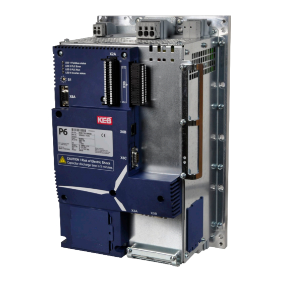
- Page 1 C O M B I V E R T Instruction Manual Pitch Inverter P6 Rated Current 45 A/52A Translation of the original manual Document Part Version 20095484...
-
Page 3: Table Of Contents
Table of contents Table of contents Preface ......................7 Information on special measures ..................7 Documentation ........................7 Validity and liability ......................8 Copyright ..........................8 1.5 Specified application ......................9 Product description ......................9 Options ..........................10 1.8 Unit identification ......................11 Safety Instructions ..................12 General instructions ......................12 Transport, storage and installation ..................12 Electrical connection ......................13 EMC Instructions .......................16... - Page 4 Table of contents Control circuit ........................31 4.3.1 Description of the terminals and controls ................31 4.3.2 LED‘s for program run and error display ................32 4.3.3 Address selector switch S1 ....................32 4.3.4 Real-time clock ........................32 4.3.5 Control terminal block X2A ....................33 4.3.5.1 External supply ..........................34 4.3.5.2 Digital outputs ...........................
- Page 5 Output voltage depending on the output current ............19 Figure 5: Dimensions and weight of the COMBIVERT P6 .............21 Figure 6: Mounting cutout for COMBIVERT P6 (provided by customer) ........22 Figure 7: Connecting wires to X1A and X1B ................24 Figure 8: Shield connection rail (Mat.Nr.
- Page 6 Table of contents List of tables Table 1: Operating conditions ....................20 Table 2: Wire-end ferrule and stripping length at X2A and X2B ...........24 Table 3: Temperature monitoring with KTY or PTC ..............28 Table 4: Function of the LED's LD1…LD4 ................32 Table 5: Measures after long storage time ................44 Table 6:...
-
Page 7: Preface
Follow these steps to get the documentation: Step 1 Read the material number (Mat.No.) from nameplate Input the material number at "www.keb.de => Service => Downloads" and click "search". Downloads Step 2 Search for specific material numbers Please enter a comlete (11-digit) material number. -
Page 8: Validity And Liability
Karl E.Brinkmann GmbH. Copyright The customer may use the instruction manual as well as further documents or parts from it for internal purposes. Copyrights are with KEB and remain valid in its entirety. -
Page 9: Specified Application
The used semiconductors and components of Karl E. Brinkmann GmbH are developed and di- mensioned for the use in industrial products. If the KEB COMBIVERT F5 is used in machines, which work under exceptional conditions or if essential functions, life-supporting measures or an extraordinary safety step must be fulfilled, the necessary reliability and security must be ensured by the machine builder. -
Page 10: Options
Preface • digital inputs and outputs, relay output (potential-free), brake control and - supply, KTY or PTC input, PT100 inputs, two encoder interfaces, field bus interface (CAN open/ProfiBus) Options The pitch inverter can be equipped with the following options: • Brake supply and control 24 V or 150...300 V •... -
Page 11: Unit Identification
Preface Unit identification 1 8 P 6 H 2 G - 3 2 Y 1 0: PROFIBUS 1: CANopen 2: Interbus Basic Pitch Library 3: PROFINET Slave 4: Powerlink Controlled Node 5: EtherCAT Slave Fieldbus interface/ A: PROFIBUS Software library B: CANopen C: Interbus Extended Pitch Library D: PROFINET Slave... -
Page 12: Safety Instructions
Safety Instructions Safety Instructions General instructions Danger Electric Shock KEB COMBIVERT units contain dangerous voltages which can cause death or serious injury. Care should be taken to ensure correct and safe operation to minimise risk to personnel and equipment. Attention... -
Page 13: Electrical Connection
Safety Instructions Attention Protect Against Accidental Contact The COMBIVERT must be protected against invalid loading. Components and covers must not be bent or moved as this may affect insulation distances. The units contain electrostatic sensitive devices which can be destroyed by inappropriate handling. For that reason the contact of electronic components and contacts is to be avoided. - Page 14 When doing an insulation measurement in accordance with VDE 0100 / Part 620, the power semiconductor of the unit and existing radio interference filters must be disconnected be- cause of the danger of destruction. This is permissible in compliance with the standard, since all inverters are given a high voltage test in the end control at KEB in accordance with EN 61800-5-1. Attention...
- Page 15 RCD (Residual Current Operated Circuit-Breaker) The intended application of P6 does not require the use of a RCD. Type "B" must be used if a RCD is required for reasons of personal or system protection. For more information please contact KEB!
-
Page 16: Emc Instructions
Keep connection cables straight (do not bundle). Install a non-assigned wire at one sides to the protective earth conductor. • The flow and return circuit must be twisted when the lines are not shielded, in order to dampen common-mode noise. • Further informations are found in the internet, see „www.keb.de“. -
Page 17: Technical Data
The power losses are smaller at smaller motors. The technical data are designed for pitch motors. When using other motors, please contact KEB. The use of a mains choke is recommended. If using functional safety of the P6 in the applica- tion (safety run with PL d according to EN 13849) an input choke is necessary ( e.g. -
Page 18: Overload Function
Technical Data Overload function (from inverter firmware 2.2.0.43) The permissible overload time is considerably depending on the cooling conditions. The over- load protection of the inverter is triggered by the following reasons: • permissible heat sink temperature is exceeded => OH („Error! Overtemperature“) • exceeding the disconnecting time in accordance with the characteristic above => OL („Er- ror! Overload“) 3.1.1 AC motor (18/19P6) -
Page 19: Dc Motor (19P6)
Technical Data 3.1.2 DC motor (19P6) Overload function (OL) Disconnecting time [s] Output current [A] Figure 3: Maximum disconnecting time depending on the output current at DC motors Maximum output voltage The maximum output voltage depending on the output current is shown in the following char- acteristic. -
Page 20: Operating Conditions
Technical Data Operating conditions Standard Standard/ Remarks class EN 61800-2 Inverter product standard: rated specifications Definition acc. EN 61800-5-1 Inverter product standard: general safety max. 3000 m above sea level Site altitude (with site altitude above 1000 m a current derating of 1 % per 100 m must be taken into consideration) Ambient conditions during operation extended to 18P6... -
Page 21: Dimensions And Weights
Technical Data Dimensions and Weights ca. 222 Weight [kg] Figure 5: Dimensions and weight of the COMBIVERT P6 Info The shield clamps are not included in the scope of delivery. -
Page 22: Mounting Cutout
M6 *) *) Threaded bolt, press nut or drilling for a M6 screw Figure 6: Mounting cutout for COMBIVERT P6 (provided by customer) Attention Ensure correct material thickness The material thickness of the rear of the cabinet must be choosen in a way, that material does not deform. -
Page 23: Hardware
Device overview Hardware Device overview Function Name Connection for external brak- ing resistor Mains input Heater input Heatsink fan for installation in – Y direction Control terminal strip Control terminal strip Ethernet Rating plate – Fieldbus Cover or internal fan for instal- –... -
Page 24: Terminals
Wire-end ferrule and stripping length at X2A and X2B A safe clamping can not be guaranteed when using shorter wire-end Attention ferrules. KEB generally recommends the use of wire-end ferrules in industrial Info environments. Press pusher by hand. Insert connecting wires into the respective hole, that no single •... -
Page 25: Shield Connection Rail
Power unit All SubD connectors have screw sockets with UNC 4-40 thread (tight- ening torque 0.4 Nm). Shield connection rails 3 x 10 mm are available for strain relief / shield Info connection of the control cables. Commercially available shield con- nection clamps (screw- or spring type) of suitable size or cable ties can be used on them. -
Page 26: Terminal Block X1B
Power unit 4.2.1.2 Terminal block X1B Terminals Function Permissible cable Strip length cross section [mm²] [mm] U, V, W Motor output 3-phase F2, U, V, W Connection for DC motor 0.75…16 Connection for batteries/ BT+, BT- ultracaps B+, B- Output for brake 24 VDC Input for temperature sen- T1, T2 Output for brake... -
Page 27: Motor Connection
Power unit 4.2.3 Motor connection 4.2.3.1 AC motor connection Terminal block X1B Name Description U, V, W Motor output T1 T2 Protective earth T1, T2 Connection for temperature sensor KTY/PTC Functional earth The encoder feedback connection is de- scribed in the control circuit. Figure 12: Motor connection AC motor 4.2.3.2 DC motor connection (option) -
Page 28: Motor Temperature Detection, Terminals T1, T2
Power unit 4.2.3.3 Motor temperature detection, terminals T1, T2 The KEB COMBIVERT P6 has a switchable KTY84/PTC evaluation. The input has „basic insulation“ to the supply respectively to the „protective separation voltage“ ! The desired func- tion is set with dr33 and works according to the following table: dr33 Function of T1, T2... -
Page 29: Control Of A 150
Instructions for switchgear use at these terminals and for the recommended switching sequence on request at KEB. Non- observance may lead to damage the switching unit or at the terminals of the COMBIVERT P6. 4.2.6 Connection of an external braking resistor The COMBIVERT P6 provides internal braking resistors as standard. -
Page 30: Connection Of The Internal Heating
1 A (characteristic B or C) Protective earth Figure 18: Connection of the internal heating The COMBIVERT P6 contains the heater elements only. Suitable controlling and monitoring of the application must be carried out by the customer about the heating contactor K2. -
Page 31: Control Circuit
Control circuit Control circuit 4.3.1 Description of the terminals and controls LED‘s Program run and error display Address selector switch Digital outputs; Relay output; Pt100 inputs; ext. 24 V supply; analog inputs (option) Digital inputs Encoder feedback channel 1 (e.g. for motor) Encoder feedback channel 2 (e.g. -
Page 32: Led's For Program Run And Error Display
Control circuit 4.3.2 LED‘s for program run and error display Description Function LD1 Fieldbus status Fieldbus driver is not activated in the PLC program; PLC program stopped or not available; another fieldbus interface than CAN assembled flashing 2.5 Hz CAN node status = pre-operational CAN node status = operational LD2 PLC Error Program OK or PLC program not available Program error, exact error cause can be determined via COMBIVIS. -
Page 33: Control Terminal Block X2A
Control circuit 4.3.5 Control terminal block X2A Function Name Pin Pin Name Function Input for external 24 V supply of the control Reference potential for board Uin 36 35 0 Vin 24 V supply digital output 2 A DO 8 34 33 COM Analog ground DO 7 32 31 0 V... -
Page 34: External Supply
Control circuit 4.3.5.1 External supply Using the external supply, the control board, I/Os, fieldbus, sensors (temperatures, humidity, mounting orientation) and the internal fan remain in operation even if the power unit is discon- nected. Input Specification : 24 V ±10 % Terminals 0Vin X2A.35 Uin X2A.36 Current consumption: 0Vin Own use 0.65 A + load currents at DO 0 ... -
Page 35: Temperature Inputs
Control circuit 4.3.5.3 Temperature inputs Input type Pt100 Connection two-wire Measuring range -40…+80 °C Terminals R0+…R3+ X2A.10/12/14/16 R0-…R3- X2A.9/11/13/15 Figure 23: Temperature inputs The inputs are not electrically isolated to the control board, so Attention that a motor temperature detection must not connected! Motor temperature measurement see chapter 4.2.3.3. -
Page 36: Control Terminal Block X2B
Control circuit 4.3.6 Control terminal block X2B Function Name Pin Pin Name Function DI 15 24 V DI 14 24 V DI 13 24 V DI 12 24 V DI 11 24 V DI 10 24 V DI 9 24 V free programmable, DI 8... -
Page 37: Encoder Interfaces
Control circuit 4.3.7 Encoder interfaces The COMBIVERT P6 has two encoder interfaces for different encoders. The encoder types are defined by parameters ec16. A total current of up to 300mA for 5V encoders and 300 mA for 24 V encoders at X3A and X3B could be take out. -
Page 38: Pin Assignment Encoder Channel 2 (X3B)
Control circuit 4.3.7.2 Pin assignment encoder channel 2 (X3B) 5 4 3 2 1 SubD-9 connector (female) 9 8 7 6 Incremental encoder TTL Input channel A Output clock signal Input channel B DAT+ Input data channel Input zero track –... -
Page 39: Diagnostic Interface X6A
8001. TCP or UDP is possible as protocol, at which encapsulated DIN66019II data telegrams will be transferred (the control unit has the node address 0, the drive unit has the node address 1). The file system can be read/written via port 8002 (only UDP) with KEB ftp-file transfer protocol (writing only with application password). Furthermore access to other ports of this interface is possible via the IEC control program (library "SysSocket"). -
Page 40: Fieldbus Interface X6C
Each user within a network can take access to the control with knowledge of the IP address. The write access via port 8001 can be restricted by parameter et09. 4.3.10 Fieldbus interface X6C The unit indentification (chapter 1.8) shows the fieldbus interface that is installed in COMBIVERT P6. 4.3.10.1 Profibus DP Signal Description –... -
Page 41: Can-Bus
Control circuit 4.3.10.2 CAN-Bus SubD-9 connec- Signal Description tor (male) reserved Not connected here CAN_L CAN-Bus signal dominant low CAN_GND Not connected here reserved Not connected here CAN_SHLD Not connected here Not connected here CAN_H CAN-Bus signal dominant high reserved Not connected here CAN_V+ Not connected here... -
Page 42: Annex A
Heater - - - - - - = no insulation –––––– = basic insulation ═════ = safe insulation (protection) according to EN 61800-5-1, rated for up to 3000 m above sea level Figure 35: Potential separation of the COMBIVERT P6... -
Page 43: Supply Of The Digital Inputs And Outputs
Annex A Supply of the digital inputs and outputs Digital outputs Imax: 250mA Imax: 250mA Imax: 250mA Imax: 2A Internal SMPS 24 V DC. Supplied from DC link Load Load Load Load Digital inputs Imax: 250mA Figure 36: Supply of the digital inputs and outputs... -
Page 44: Storage
Annex A Storage The DC link of the KEB COMBIVERT is equipped with electrolytic capacitors. If electrolytic capacitors are stored de-energized, the oxide film acting as dielectric medium reacts with the acidic electrolyte and degrades itself slowly. This affects the dielectric strength and the capacity. -
Page 45: Fault Remedy
Cyclical maintenance Fault Remedy A defective device should only be repaired by KEB or an authorized partner. Defective com- ponents, modules or options may only be replaced by original parts. The device must be returned in original packaging with a detailed bug report. - Page 46 Revision history History of changes: Revision Date Description 2011-11 First published version with material number 00P6NEB-0000 2011-12 Technical data adapted, maximum current for encoder interfaces inserted 2012-04 Notes for the seal at the heat sink inserted 2015-04 Complete revision. Changeover to documents management 20095484...
- Page 47 Notes...
- Page 48 +39 02 3353531 • fax: +39 02 33500790 net: www.keb.de • mail: kebitalia@keb.it KEB Power Transmission Technology (Shanghai) Co.,Ltd. No. 435 Qianpu Road, Chedun Town, Songjiang District, KEB Japan Ltd. CHN-Shanghai 201611, P.R. China 15–16, 2–Chome, Takanawa Minato-ku fon: +86 21 37746688 • fax: +86 21 37746600...
Need help?
Do you have a question about the COMBIVERT P6 and is the answer not in the manual?
Questions and answers