
Related Manuals for KEB COMBIVERT P6


Summary of Contents for KEB COMBIVERT P6
- Page 1 COMBIVERT P6 INSTRUCTIONS FOR USE | INSTALLATION P6 PITCH INVERTER 18 / 19 / 23P6 HOUSING G, R Translation of the original manual Document 20095484 EN 02...
-
Page 3: Preface
The hardware and software described in this document are products of KEB. The infor- mation contained in this document is valid at the time of publishing. KEB reserves the right to update this document in response to misprints, mistakes or technical changes. -
Page 4: Laws And Guidelines
The customer may use the instructions for use as well as further documents or parts from it for internal purposes. Copyrights are with KEB and remain valid in its entirety. This KEB product or parts thereof may contain third-party software, including free and/ or open source software. -
Page 5: Table Of Contents
TAbLE Of CONTENTS Table of Contents Preface ..............................3 Signal words and symbols ......................3 More symbols ..........................3 Laws and guidelines ........................4 Warranty and liability ........................4 Support ............................4 Copyright ............................4 Table of Contents ........................... 5 List of figures ............................8 List of Tables ............................ - Page 6 TAbLE Of CONTENTS 3.1.4 Electrical operating conditions .................... 28 3.1.4.1 Device classification ......................28 3.1.4.2 Electromagnetic compatibility ..................28 3.2 Electrical data ..........................29 3.2.1 Braking resistor ........................30 3.2.2 Other inputs/outputs of the power unit ................30 3.3 Overload function .......................... 31 3.3.1 AC-Motor (18 / 19 / 23P6) .....................
- Page 7 TAbLE Of CONTENTS 5.7.2 DC motor connection (19P6 DC only) ................51 5.7.3 Motor temperature detection ....................52 5.8 brake connection .......................... 53 5.8.1 Connection of a 24 V Brake (18/19P6 only) ............... 53 5.8.2 Connection of a high voltage brake ..................53 5.9 Connection of batteries / ultracapacitors ..................
-
Page 8: List Of Figures
Mounting cutout for COMBIVERT P6 (provided by customer) ......... 36 Figure 8: Dimensions and weight of the COMBIVERT P6 housing R ..........37 Figure 9: Mounting cutout for COMBIVERT P6 housing R (provided by customer) ....... 38 Figure 10: Top view of housing G...................... 39 Figure 11: Rear view of housing G.................... - Page 9 RS232 cable for diagnostic interface ................68 Figure 53: PROFIBUS DP interface ....................70 Figure 54: CAN-Bus interface ......................70 Figure 55: Potential insulation of the COMBIVERT P6 ..............71 Figure 56: Supply of the digital inputs and outputs ................72...
-
Page 10: List Of Tables
LIST Of TAbLES List of Tables Table 1: Type code ........................25 Table 2: Climatic ambient conditions ..................... 26 Table 3: Mechanical ambient conditions ..................27 Table 4: Chemical / mechanical active substances ............... 27 Table 5: Device classification......................28 Table 6: Electromagnetic compatibility ..................28 Table 7: Electrical data ........................29 Table 8:... -
Page 11: Glossary
(DIN 5008) IP xx Degree of protection (xx for level) Fieldbus system KEB product The KEB product is subject of this Cyclic duration factor manual Complete drive module including Silicium temperature sensor (pola- auxiliary equipment (control cabinet) - Page 12 GLOSSARy Term used in the safety technology (EN 61508-1...7) for the size of error probability per hour Programmable logic controller Pt100 Temperature sensor with R0=100Ω Pt1000 Temperature sensor with R0=1000Ω PTC-resistor for temperature detec- tion Pulse width modulation RJ45 Modular connector with 8 lines Synchronous sensorless closed loop SELV Safety Extra Low Voltage (<...
-
Page 13: Standards For Drive Controllers
STANDARDS fOR DRIVE CONTROLLERS Standards for drive controllers Product standards that apply directly to the drive controller EN 61800-2 Adjustable speed electrical power drive systems - Part 2: General requirements - Rating specifications for low voltage adjustable frequency a.c. power drive systems (VDE 0160-102, IEC 61800-2) EN 61800-3 Speed-adjustable electrical drives. Part 3: EMC requirements and specific test methods (VDE 0160-103, IEC 61800-3) EN 61800-5-1 Adjustable speed electrical power drive systems - Part 5-1: Safety requirements - Electrical, thermal and energy (IEC 61800-5-1);... -
Page 14: Standards That Are Used In The Environment Of The Drive Controller
STANDARDS fOR DRIVE CONTROLLERS EN 61000-4-5 Electromagnetic compatibility (EMC) - Part 4-5: Testing and measurement techniques - Surge immunity test (IEC 61000-4-5); German version EN 61000-4-5 EN 61000-4-6 Electromagnetic compatibility (EMC) - Part 4-6: Testing and measurement techniques - Immunity to conducted disturbances, induced by radio-frequency fields (IEC 61000-4-6); German version EN 61000-4-6 EN 61000-4-34 Electromagnetic compatibility (EMC) - Part 4-34: Testing and measurement... -
Page 15: Basic Safety Instructions
Hazards and risks through ignorance. ► Read the instructions for use ! ► Observe the safety and warning instructions ! ► If anything is unclear, please contact KEB Automation KG ! 1.1 Target group These instructions for use are intended exclusively for qualified electricians.Electrical... -
Page 16: Installation
bASIC SAfETy INSTRUCTIONS 1.3 Installation DANGER Do not operate in an explosive environment! ► The COMBIVERT is not intended for the use in potentially explosive environment. CAUTION Design-related edges and high weight! Contusions and bruises! ► Never stand under suspended loads. ►... -
Page 17: Electrical Connection
bASIC SAfETy INSTRUCTIONS 1.4 Electrical connection DANGER Voltage at the terminals and in the device ! Danger to life due to electric shock ! ► Never work on the open device or never touch exposed parts. ► Wait until all drives has been stopped in order that no regenerative energy can be generated. -
Page 18: Emc-Compatible Installation
Due to the radio interference suppression capacitors, the test generator will switch off immediately with a current fault. According to it is permissible to disconnect already tested com- EN 60204-1 ponents. Drive controllers of the KEB Automation KG are delivered ex works voltage tested to 100% according to product standard. -
Page 19: Insulation Measurement
During operation, all covers and doors shall be kept closed. • Use only approved accessories for this device. • Never touch terminals, busbars or cable ends. If a P6 drive controller has not been in operation for more than a year, observe the following information. www.keb.de/fileadmin/media/Techinfo/dr/tn/ti_dr_tn-format-capaci- tors-00009_en.pdf... -
Page 20: Maintenance
Unpredictable malfunctions! ► The function of the drive controller is dependent on its parameteri- zation. Never replace without knowledge of the application. ► Modification or repair is permitted only by KEB Automation KG au- thorized personnel. ► Only use original manufacturer parts. ► Infringement will annul the liability for resulting consequences. -
Page 21: Disposal
SAfETy INSTRUCTIONS 1.8 Disposal Electronic devices of the KEB Automation KG are exclusively professional devices for further industrial processing (so-called B2B devices). Manufacturers of B2B devices are obliged to take back and recycle devices manufac- tured after 14.08.2018. These devices may not be disposed at the collection centres of public sector disposal organisations. -
Page 22: Product Description
As part of the safety system, the COMBIVERT P6 drive controllers can protect the wind turbine from a dangerous overspeed or bring it to a standstill in case of a turbine fault by quickly turning the rotor blades "out of the wind". -
Page 23: Product Features
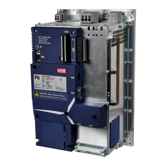
COMBIVERT P6 Power range: 18...42 kW / 400 V Housing: G, R The COMBIVERT P6 is an "all-in-one" drive controllerr for pitch applications, which is characterised by the following features: • Control of induction, synchronous and DC motors • Braking resistor integrated •... -
Page 24: Options
PRODUCT DESCRIPTION 2.4 Options The pitch drive controller can be equipped with the following options: • Brake supply and control 24 V (18 / 19P6) or 50…300 V (18 / 19 / 23P6) • Output 24 V / 4.2 A can be used for customer components if no 24 V brake is con- nected (18 / 19P6) •... -
Page 25: Type Code
A: 12 Ω B: 10 Ω G: without sensors (humidity, mounting orientation, analog inputs) Control type H: with sensors (humidity, mounting orientation, analog inputs) Series COMBIVERT P6 Inverter size 18, 19, 23 Table 1: Type code EtherCAT is a registered trademark and patented technology licensed by the Beckhoff ®... -
Page 26: Technical Data
OPERATING CONDITIONS 3 Technical Data 3.1 Operating conditions 3.1.1 Climatic ambient conditions Storage Standard Class Descriptions Ambient temperature EN 60721-3-1 Extended to -40°C…70°C Relative humidity 5…95 % (without condensation) EN 60721-3-1 Storage altitude – – Max. 3000 m above sea level Transport Standard Class... -
Page 27: Mechanical Ambient Conditions
OPERATING CONDITIONS 3.1.2 Mechanical ambient conditions Storage Standard Class Descriptions Vibration amplitude 3.0 mm (2…9 Hz) EN 60721-3-1 Acceleration amplitude 10 m/s² (9…200 Hz) Vibration limits EN 61373 – Railway – – Germ. Lloyd, 7-2 Shock limits 100 m/s²; 11 ms EN 60721-3-1 Transport Standard... -
Page 28: Electrical Operating Conditions
OPERATING CONDITIONS 3.1.4 Electrical operating conditions 3.1.4.1 Device classification Requirement Standard Class Descriptions Only for the heating circuit => „5.11 Connection of the internal heating“ Overvoltage category EN 61800-5-1 – Non-conductive pollution, occasional conden- Pollution degree EN 60664-1 sation when PDS is out of service Table 5: Device classification 3.1.4.2 Electromagnetic compatibility... -
Page 29: Electrical Data
Calculated losses at cabinet side + heat sink side, at 50% output voltage, 100% output current and rated switching frequency. The power losses are smaller at smaller motors. The technical data are designed for pitch motors. When using other motors, please contact KEB. -
Page 30: Braking Resistor
ELECTRICAL DATA 3.2.1 braking resistor The devices can be equipped with different braking resistors. The configuration is speci- fied in the 6th digit of the material number, => „2.5 Type code“. Inverter size 18 / 19 / 19 DC 6. Digit of the material number Braking resistor (integrated) / Ω – – Energy absorption capacity / kJ – – braking resistor (integrated) Continuous power braking resistor (integrated) –... -
Page 31: Overload Function
OVERLOAD fUNCTION 3.3 Overload function Valid for drive controllers from firmware version 2.2.0.43. The overload duration achievable in practice depends essentially on the cooling condi- tions. The overload protection of the drive controller is triggered by the following causes: • Permissible heat sink temperature is exceeded, leading to the error message "OH (Error overheat powermodules)". -
Page 32: Overload Function In The Lower Speed Range (Ol2) For 18 / 19P6
OVERLOAD fUNCTION 3.3.1.2 Overload function in the lower speed range (OL2) for 18 / 19P6 In the lower speed range the permissible output current is depending on the output fre- quency. Depending on the setting of parameter is14, if the output current is exceeded, the error E.OL2 is triggered or the output current is limited. -
Page 33: Overload Function In The Lower Speed Range (Ol2) For 23P6
OVERLOAD fUNCTION 3.3.1.3 Overload function in the lower speed range (OL2) for 23P6 In the lower speed range the permissible output current is depending on the output fre- quency. Depending on the setting of parameter is14, if the output current is exceeded, the error E.OL2 is triggered or the output current is limited. -
Page 34: Dc Motor (19P6 Dc)
OVERLOAD fUNCTION 3.3.2 DC motor (19P6 DC) 3.3.2.1 Overload function (OL) Output current in A Figure 4: Maximum tripping time depending on the output current at DC motors 3.3.2.2 Maximum output voltage The maximum output voltage depending on the output current is shown in the following characteristic. -
Page 35: Dimensions And Weights
DIMENSIONS AND WEIGHTS 3.4 Dimensions and weights 3.4.1 Housing G gasket for M6 Housing Weight 16 kg Dimensions All dimensions in mm Figure 6: Dimensions and weight of the COMBIVERT P6 housing G... -
Page 36: Mounting Cutout Housing G
DIMENSIONS AND WEIGHTS 3.4.2 Mounting cutout housing G Figure 7: Mounting cutout for COMBIVERT P6 (provided by customer) NOTICE Ensure correct material thickness ! The material thickness of the cabinet back wall and the mounting meth- od must be chosen that way the material does not bend. Together with the rubber seal of the P6, protection class IP54 is maintained. -
Page 37: Housing R
DIMENSIONS AND WEIGHTS 3.4.3 Housing R gasket for M8 Housing 47 kg (external braking resistor) Weight 50 kg (internal braking resistor) Dimensions All dimensions in mm Figure 8: Dimensions and weight of the COMBIVERT P6 housing R... -
Page 38: Mounting Cutout Housing R
DIMENSIONS AND WEIGHTS 3.4.4 Mounting cutout housing R Figure 9: Mounting cutout for COMBIVERT P6 housing R (provided by customer) NOTICE Ensure correct material thickness ! The material thickness of the cabinet back wall and the mounting meth- od must be chosen that way the material does not bend. Together with the rubber seal of the P6, protection class IP54 is maintained. -
Page 39: Device Overview
DEVICE OVERVIEW 4 Device overview 4.1 Top view of housing G No. function Name LEDs – Address selector switch Diagnostic interface COMBIVIS Control terminal block Control terminal block Shield connection rail / – strain relief Ethernet interface (for COMBIVIS / COMBIVIS studio 6 only) Rating plate –... -
Page 40: Front View Of Housing G
DEVICE OVERVIEW 4.3 front view of housing G No. function Name 24 V brake / motor temperature sensor High-voltage brake and measuring input X3A / 17 Encoder inputs Interior fan Y direction or – cover Connection for batteries / ultraca- –... -
Page 41: Top View Of Housing R
DEVICE OVERVIEW 4.5 Top view of housing R No. function Name Address selector switch LEDs – Diagnostic interface COMBIVIS Lifting eyes – Control terminal block Control terminal block Shield connection rail / – strain relief Ethernet interface (for COMBIVIS / COMBIVIS studio 6 only) Fieldbus interface 10 Rating plate... -
Page 42: Front View Of Housing R
DEVICE OVERVIEW 4.7 front view of housing R No. function Name 17 Connection for batteries / ultracaps High-voltage brake / motor temperature sensor / 24 V output / measuring inputs 19 Motor connection X3A / 20 Encoder inputs 21 Interior fan Y-direction or cover –... -
Page 43: Accessories
DEVICE OVERVIEW 4.9 Accessories 4.9.1 Shield connection rail For EMC conform installation of the power cables a shield connection rail is available as option. Commercially available shield connection clamps for rails 3x10 mm can be used. The Shield connection clamps (screw or spring type) must match the to cable diameter and are therefore not included. -
Page 44: Power Unit
POWER UNIT 5 Power unit 5.1 Terminal block X1A size 18 / 19 Terminals function Cable cross-section in mm² Stripping length in mm L1, L2, L3 Mains input 3-phase 0.75…16 External braking resistor RB+, RB- 0.75…16 (optional) Input for heating 400 V H1, H2 0.25…6 (optional) -
Page 45: Terminal Block X1B Size 18 / 19
POWER UNIT 5.2 Terminal block X1b size 18 / 19 Cable cross-section Stripping length Terminals function in mm² in mm U, V, W Motor output 3-phase 0.75…16 F2, U, V, W Connection for DC motor BT+, BT- Connection for batteries / ultracaps B+, B- Output for brake DC 24 V T1, T2... -
Page 46: Terminal Block X1A Size 23
POWER UNIT 5.3 Terminal block X1A size 23 Terminals function Cable cross-section in mm² Stripping length in mm for 10...25 mm² 10…50 L1, L2, L3 Mains input 3-phase for 35...50 mm² External braking resistor RB+, RB- 0.75…16 (optional) Input for heating 400 V H1, H2 0.25…6 (optional) -
Page 47: Terminal Block X1B Size 23
POWER UNIT 5.4 Terminal block X1b size 23 Terminals function Cable cross-section in mm² Stripping length in mm U, V, W Motor output 3-phase for 10...25 mm² 10…50 Connection for batteries / BT+, BT- for 35...50 mm² ultracaps 24V, 0V DC 24 V output BTM0... -
Page 48: Connecting Cables To X1A And X1B
POWER UNIT 5.5 Connecting cables to X1A and X1b 5.5.1 Grey terminals Stripping the cables ► Strip the cable according to specifications. =>„5.1 Terminal block X1A size 18 / 19“ „5.2 Terminal block X1B size 18 / 19“ =>„5.3 Terminal block X1A size 23“ „5.4 Terminal block X1B size 23“. -
Page 49: Orange Terminals (23P6 Only)
POWER UNIT 5.5.2 Orange terminals (23P6 only) ► Strip the cable according to specifications. =>„5.3 Terminal block X1A size 23“ „5.4 Terminal block X1B size 23“. ► Use wire end ferrules if necessary. ► Place the stripped area (or wire end ferrule) on the marked surface. ►... -
Page 50: Mains Connection
POWER UNIT 5.6 Mains connection Terminal block X1A L3 PE F1...F3 Name function L1, L2, L3 Mains input 3-phase 400 V F1...F3 Mains fuses Mains switch or mains contactor (depending on application) Mains choke (recommended) [required for "functional safety" and size 23] Protective earth Figure 26: Mains connection... -
Page 51: Motor Connection
POWER UNIT 5.7 Motor connection 5.7.1 AC motor connection Connection of encoder feedback => „6.3.3 Encoder interfaces“. Terminal block X1b T1 T2 Name function U, V, W Motor output T1, T2 Connection for temperature sensor KTY / PTC / Pt1000 Protective earth Figure 27: Motor connection AC motor... -
Page 52: Motor Temperature Detection
POWER UNIT 5.7.3 Motor temperature detection The COMBIVERT P6 has a switchable KTY84 / PTC / Pt1000 evaluation. The input has „basic insulation“ to the supply and to the „safely insulated voltage“ (control board volt- age)! The desired function is set with dr33 and works according to the following table:... -
Page 53: Brake Connection
POWER UNIT 5.8 brake connection 5.8.1 Connection of a 24 V brake (18/19P6 only) Terminal block X1b = 24V Name function Output for direct brake control. A free-wheeling diode is internally installed. Figure 30: Connection of a 24 V-Brake (18/19P6 only) 5.8.2 Connection of a high voltage brake Output for direct control of a high voltage brake with a rated voltage of U 50…300 V. -
Page 54: Connection Of Batteries / Ultracapacitors
There is no internal inrush current limiting at terminals BT+ and BT-. Therefore, energy storages should only be connected if they are di- scharged. Instructions for switchgear use at these terminals and for the recommended switching sequence on request at KEB. Non-observan- ce may lead to damage of the switchgear. -
Page 55: Connection Of An External Braking Resistor
5.10 Connection of an external braking resistor The COMBIVERT P6 provides internal braking resistors as standard. If the COMBIVERT P6 is equipped with the option "for external braking resistor", the braking resistor must be connected with shielded cable at RB+ und RB-. -
Page 56: Connection Of The 24V Output (23P6 Only)
POWER UNIT 5.12 Connection of the 24V output (23P6 only) Terminal block X1b = 24V Name function 24 V output to supply external components; buffered from the energy 24 V storage.This output is not switched by the 23P6 software, it is only monitored for short circuits/overloads. Figure 35: Connection of the 24V output (23P6 only) -
Page 57: Control Unit
DESCRIPTION Of THE INDICATORS AND CONTROLS 6 Control unit 6.1 Description of the indicators and controls Name Description LEDs Program run and error display Address selector switch Digital outputs; Relay output; Pt100 inputs; ext. 24 V supply; analog inputs (option) Digital inputs Encoder feedback channel 1 (e.g. -
Page 58: Leds For Program Run And Error Display
DESCRIPTION Of THE INDICATORS AND CONTROLS 6.1.1 LEDs for program run and error display Description function LED1 Fieldbus status Fieldbus driver is not activated in the PLC program; PLC program stopped or not available; fieldbus interface other than CAN equipped Flashing (2.5 Hz) CAN node status = pre-operational CAN node status = operational LED2 PLC Error Program OK or PLC program not available... -
Page 59: Connection Instructions Control Unit
– 10…12 mm ferrule single-wire or fine-wire Table 13: Wire-end ferrules and stripping length KEB generally recommends the use of wire-end ferrules in industrial environ- ments. front view terminal block a) Pusher b) Wire hole Figure 37: Assembly of the control cable •... -
Page 60: Shield Connection
DESCRIPTION Of THE INDICATORS AND CONTROLS 6.2.2 Shield connection Shield connection rails 3x10 mm are available for strain relief / shield connection of the control cables. Commercially available shield connection clamps (screw- or spring type) of suitable size or cable ties can be used on them. 6.2.3 D-SUb sockets and plugs All D-SUB connectors have screw sockets with UNC 4-40 thread (tightening torque 0.4 Nm). -
Page 61: Description Of The Terminals
DESCRIPTION Of THE TERMINALS 6.3 Description of the terminals 6.3.1 Control terminal block X2A function Name PIN PIN Name function Input for external 24 V supply Reference potential for 24 V of the control board 0 Vin supply Digital output 2 A DO 8 DO 7 DO 6... -
Page 62: External Supply Of The Control Board
DESCRIPTION Of THE TERMINALS 6.3.1.1 External supply of the control board Using the external supply, the control board, I/Os, fieldbus, sensors (temperatures, hu- midity, mounting orientation) and the interior fan (of 18/19P6) remain in operation even if the power unit is disconnected. Terminals Specification X2A.35 0Vin : 24 V ±10 % X2A.36 Others Current consumption:... -
Page 63: Temperature Inputs
DESCRIPTION Of THE TERMINALS 6.3.1.3 Temperature inputs Terminals Input type X2A.10/12/14/16 R0+…R3+ Pt100 X2A.9/11/13/15 R0-…R3- Connection Measuring range two-wire -40…+80 °C Figure 42: Temperature inputs NOTICE No potential separation ! The inputs are not electrically isolated from the control board, therefore a motor temperature sensor must not be connected! =>... -
Page 64: Control Terminal Block X2B
DESCRIPTION Of THE TERMINALS 6.3.2 Control terminal block X2b function Name Name function DI 15 24 V DI 14 24 V DI 13 24 V DI 12 24 V DI 11 24 V DI 10 24 V DI 9 24 V Free programmable, DI 8... -
Page 65: Encoder Interfaces
DESCRIPTION Of THE TERMINALS 6.3.3 Encoder interfaces The COMBIVERT P6 has two encoder interfaces for different encoders. The encoder types are defined by parameters ec16. A total current of up to 300 mA for 5 V encoders and 300 mA for 24 V encoders can be drawn at X3A and X3B. Figure 47: Encoder interfaces 6.3.3.1 Pin assignment encoder channel 1 (X3A) Socket D-SUb-15 9 8 7 15 14 13 12 11... -
Page 66: Table 14: Resolver Specification
5 V incremental encoders (Heidenhain, Kübler, Sick-Stegmann). NOTICE Connection of third-party motors ! For resolver connection KEB signal names are used in the above table. They match with KEB motors and KEB cables. If connecting third-party motors, other definitions of the signal names are often used, which can result in a reverse rotational direction. Connection instructions upon re- quest. -
Page 67: Pin Assignment Encoder Channel 2 (X3B)
DESCRIPTION Of THE TERMINALS 6.3.3.2 Pin assignment encoder channel 2 (X3B) Socket D-SUb-9 5 4 3 2 1 9 8 7 6 Incremental encoder TTL Input channel A Output clock signal Input channel B DAT+ Input data channel Input zero track –... -
Page 68: Diagnostic Interface X6A
DESCRIPTION Of THE TERMINALS 6.3.4 Diagnostic interface X6A The socket X6A is a serial RS232/485 interface. It serves for the connection of the con- trol with a PC or other operating units via the protocol DIN66019II. The control unit has the node address 0, the drive unit has the node address 1. -
Page 69: Ethernet Interface (X6B)
DIN66019II data telegrams will be transferred (the control unit has the node address 0, the drive unit has the node address 1). The file system can be read/written via port 8002 (only UDP) with KEB FTP file transfer protocol (writing only with application password). Furthermore, other ports of this interface can be accessed via the IEC control program. The interface supports automatic polarity detection, Auto- Crossover and automatic speed detection, adjustable by parameter Et15. -
Page 70: Fieldbus Interface X6C
6.3.6 fieldbus interface X6C The type code (=> code“) shows the fieldbus interface that is installed in „2.5 Type COMBIVERT P6. 6.3.6.1 Profibus DP The connection is described in the installation instruction (8.021). This can be down- loaded from www.profibus.com. Socket D-SUb-9... -
Page 71: Functional Overview
50 … 300 V Heater ─ ─ ─ ─ No insulation ─ • ─ • ─ Functional insulation –––––– –––––– Basic insulation ═════ ═════ Safe insulation (protection) according to 61800-5-1, rated for up to 3000 m above sea level Figure 55: Potential insulation of the COMBIVERT P6... -
Page 72: Supply Of The Digital Inputs And Outputs
fUNCTIONAL OVERVIEW 7.2 Supply of the digital inputs and outputs Digital outputs : 250mA : 250mA : 250mA : 2A _max _max _max _max Internal SMPS 24 V DC, supplied from DC link Load Load Load Load Digital inputs : 250mA _max Figure 56: Supply of the digital inputs and outputs... -
Page 73: Certification
Not planned for 18/19P6. For 23P6 only: Acceptance according to UL is marked at KEB drive controllers with the adjacent logo on the nameplate. To be conform according to UL for use on the North American and Canadian Market the... - Page 74 CERTIfICATION • Push through heat sink part only: For the heat sink extending the ultimate enclosure – “Type 1 Enclosure” • Brake resistor ratings and duty cycle: Internal resistors • Duty cycle 1% • Max. 1.2 sec on-time, (118.8 sec off-time) External resistors • Duty cycle 10% • Max. 12 sec on-time, (108 sec off-time) •...
-
Page 75: Further Informations And Documentation
CERTIfICATION 8.3 further informations and documentation You find supplementary manuals and instructions for the download under www.keb.de/service/downloads General instructions • EMC and safety instructions • Manuals for control boards, safety modules, fieldbus modules, etc. Instruction and information for construction and development • Input fuses in accordance with UL • Programming manual for control and power unit •... -
Page 76: Revision History
2012-04 Notes for the seal at the heat sink inserted 2015-01 Complete revision. Changeover to documents management 20095484 2019-10 - For internal use only - changeover to new KEB CI optics, extension by device size 23 Extension of detailed technical data for device size 23, preciseing technical data for... - Page 77 / Mitjer, Nave 8 - Pol. Ind. LA MASIA E-Mail: info@keb.cz Internet: www.keb.cz 08798 Sant Cugat Sesgarrigues (Barcelona) Spain Tel: +34 93 8970268 Fax: +34 93 8992035 E-Mail: vb.espana@keb.de Société Française KEB SASU france Z.I. de la Croix St. Nicolas 14, rue Gustave Eiffel...
- Page 78 Automation with Drive www.keb.de KEB Automation KG Suedstrasse 38 32683 Barntrup Tel. +49 5263 401-0 E-Mail: info@keb.de...
Need help?
Do you have a question about the COMBIVERT P6 and is the answer not in the manual?
Questions and answers