Sign In
Upload
Manuals
Brands
Hitachi Manuals
Inverter
WJ200-001S
Hitachi WJ200-001S Manuals
Manuals and User Guides for Hitachi WJ200-001S. We have
5
Hitachi WJ200-001S manuals available for free PDF download: Instruction Manual, Quick Reference Manual
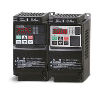
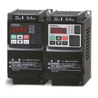
Hitachi WJ200-001S Instruction Manual (421 pages)
WJ200 Series Single-phase Input 200V class Three-phase Input 200V class Three-phase Input 400V class
Brand:
Hitachi
| Category:
Inverter
| Size: 4.69 MB
Table of Contents
2
Caution When Using Safe Stop Function
2
Definitions and Symbols
2
Hazardous High Voltage
2
Safety Messages
3
General Precautions - Read These First
5
Index to Warnings and Cautions in this Manual
7
Wiring – Cautions for Electrical Practice
8
Powerup Test Caution Messages
9
Cautions for Configuring Drive Parameters
9
Warnings for Configuring Drive Parameters
10
Cautions for Operations and Monitoring
11
General Warnings and Cautions
11
Warnings and Cautions for Troubleshooting and Maintenance
15
Terminal Symbols and Screw Size
16
Fuse Sizes
17
Table of Contents
19
Revisions
20
Contact Information
21
Getting Started
22
Chapter 1 : Getting Started
22
Introduction
22
Main Features
23
Inverter Specification Label
24
Model-Specific Tables for 200V and 400V Class Inverters
24
WJ200 Inverter Specifications
28
General Specifications
31
Derating Curves
38
Introduction to Variable-Frequency Drives
38
The Purpose of Motor Speed Control for Industry
38
What Is an Inverter
39
Inverter Input and Three-Phase Power
39
Torque and Constant Volts/Hertz Operation
40
Inverter Output to the Motor
41
Braking
41
Intelligent Functions and Parameters
42
Velocity Profiles
43
Frequently Asked Questions
46
Inverter Mounting and Installation
47
Chapter 2 : Inverter Mounting and Installation
47
Main Physical Features
47
Orientation to Inverter Features
47
Unpacking and Inspection
48
Power Wiring Access
49
Basic System Description
51
Step-By-Step Basic Installation
52
Choosing a Mounting Location
53
Ensure Adequate Ventilation
53
Keep Debris out of Inverter Vents
54
Check Inverter Dimensions
60
Prepare for Wiring
61
Determining Wire and Fuse Sizes
62
Terminal Dimensions and Torque Specs
63
Wire the Inverter Input to a Supply
67
Logic Control Wiring
67
Wire the Inverter Output to Motor
68
Goals for the Powerup Test
68
Powerup Test
68
Uncover the Inverter Vents
69
Powering the Inverter
69
Pre-Test and Operational Precautions
70
Key and Indicator Legend
70
Using the Front Panel Keypad
71
Keypad Navigation Map
71
Keys, Modes, and Parameters
74
Selecting Functions and Editing Parameters
76
Set the Motor Base Frequency and AVR Voltage of the Motor
77
Set the Motor Current
78
Set the Number of Motor Poles
79
Monitoring Parameters with the Display
79
Running the Motor
80
Single-Digit Edit Mode
81
Powerup Test Observations and Summary
82
Configuring Drive Parameters
83
Choosing a Programming Device
83
Introduction of Inverter Programming
84
Chapter 3 : Configuring Drive Parameters
84
Using the Keypad Devices
85
Control Algorithms
85
Operational Modes
85
Run Mode Edit
86
Dual Rating Selection
88
“D” Group: Monitoring Functions
90
Trip Event and History Monitoring
91
Local Monitoring with Keypad Connected
92
“F” Group: Main Profile Parameters
93
“A” Group: Standard Functions
94
Run Command Source Setting
96
Basic Parameter Settings
97
Analog Input Settings
99
Ezsq Related Settings
100
Multi-Speed and Jog Frequency Setting
102
Jog Frequency
103
Torque Control Algorithms
105
Manual Torque Boost
105
Voltage Compensation Gain and Slip Compensation Gain
105
Voltage Gain
107
DC Braking (DB) Settings
109
Frequency-Related Functions
110
Jump Frequencies
111
Acceleration Stop/Deceleration Stop
112
PID Control
114
PID Loop Configuration
115
PID Sleep Function
116
Automatic Voltage Regulation (AVR) Function
117
Energy Savings Mode / Optional Accel/Decel
118
Second Acceleration and Deceleration Functions
119
Accel/Decel
120
A131 Curve Constant (Swelling)
120
A150~A153 Curvature of EL-S-Curve
120
Acceleration / Deceleration Pattern Summary
121
Additional Analog Input Settings
122
Analog Input Calculate Function
123
Add Frequency
124
Input Range Settings
125
Automatic Restart Mode
125
B" Group: Fine Tuning Functions
128
Active Frequency Matching Restart
129
Electronic Thermal Overload Alarm Setting
130
Electronic Thermal Characteristic
130
Electronic Thermal Characteristic Curve
131
Electronic Thermal Warning Output
132
Current Limitation Related Functions
132
Over-Current Trip Suppression
132
Overload Restriction
134
Software Lock Mode
135
Motor Cable Length Parameter
136
Rotation Restriction Related Parameters
136
Run/Power on Warning Time
137
Reduced Voltage Start
138
Display Related Parameters
139
Basic Display Mode
139
Data Comparison Display Mode
139
User Setting Display Mode
142
Automatic User Parameter Registration
142
User Parameter Registration
143
Analog Voltage Input Mode
143
Quadrant-Specific Setting Mode
143
Terminal-Switching Mode
143
Torque Limit Function
145
Controlled Stop Operation at Power Loss
148
Window Comparator, Analog Disconnection
149
Ambient Temperature Setting
149
Watt-Hour Related
150
Carrier Frequency (PWM) Related
151
Miscellaneous Settings
153
Stop Mode / Restart Mode Configuration
156
Brake Control Function Related
159
DC Bus AVR (Automatic Voltage Regulation) for Deceleration Settings
160
Inverter Mode Setting
160
STO (Safe Torque Off) Setting
162
Password Function
163
How to Authenticate Password
163
How to Change Password
163
How to Delete Password
164
C" Group: Intelligent Terminal Functions
165
Intelligent Input Terminal Overview
166
Input Function Summary Table
170
Output Terminal Configuration
172
Output Function Summary Table
175
Low Load Detection Parameters
176
Frequency Arrival Output
176
Output Function Adjustment Parameters
176
Overload Warning Output
176
PID FBV Output
179
Network Communications Settings
180
Analog Input Signal Calibration Settings
181
Miscellaneous Functions
182
Analog Output Calibration Related Functions
183
Output Logic and Timing
184
Other Functions
185
“H” Group: Motor Constants Functions
187
Motor Constants Selection
188
Sensorless Vector Control
189
Auto-Tuning Function
191
Off-Line Auto-Tuning Procedure (with Motor Rotation)
192
Option Card Error
192
“P” Group: Other Parameters
193
Encoder (Pulse Train Input) Related Settings
194
Torque Command Related Settings
195
Simple Positioning
195
2-Phase Pulse Input
196
Single Phase Pulse Input
197
Simple Positioning Setting
200
Multistage Position Switching Function (CP1/CP2/CP3)
201
Speed/Positioning Switching Function (SPD)
202
Homing Function
203
Ezsq User Parameter Related Settings
204
Operations and Monitoring
205
Caution Messages for Operating Procedures
205
Chapter 4 : Operations and Monitoring
205
Introduction
206
Warning Messages for Operating Procedures
207
Connecting to Plcs and Other Devices
208
Example Wiring Diagram
209
Control Logic Signal Specifications
210
Wiring Sample of Control Logic Terminal (Source Logic)
211
Sink/Source Logic of Intelligent Input Terminals
211
Wire Size for Control and Relay Terminals
212
How to Connect?
212
Recommended Ferrule
213
Intelligent Inputs
213
Intelligent Terminal Listing
214
Intelligent Outputs
215
Using Intelligent Input Terminals
219
Forward Run/Stop and Reverse Run/Stop Commands
220
Multi-Speed Select ~Binary Operation
221
Programming Using the CF Switches
221
Standard Keypad Programming
222
Jogging Command
223
External Signal for DC Braking
224
Set Second Motor, Special Set
225
Two Stage Acceleration and Deceleration
226
Free-Run Stop
227
External Trip
228
Unattended Start Protection
229
Commercial Power Source Switchover
230
Software Lock
231
Analog Input Current/Voltage Select
232
Reset Inverter
233
Thermistor Thermal Protection
234
Three-Wire Interface Operation
235
PID ON/OFF and PID Clear
236
Remote Control up and down Functions
238
Force Operation from Digital Operator
240
Overload Restriction Source Changeover
241
Brake Confirmation
241
Torque Limit Switch
242
LAD Cancellation
243
Pulse Counter Clear
244
Add Frequency Enable
245
Force Terminal Mode
245
Permission for Torque Command Input
246
Clearance of Cumulative Power Data
247
General Purpose Input
248
Analog Command Hold
249
Multistage-Position Switch
250
Limit Signal of Homing, Trigger Signal of Zero-Return
251
Speed/Position Changeover
252
Executing Ezsq Program
252
Retain Output Frequency
252
Safe Stop Related Signals
253
Display Limitation
253
Permission of Run Command
253
Rotation Direction Detection
254
Sinking Outputs, Open Collector
254
Using Intelligent Output Terminals
255
Internal Relay Output
256
Output Signal ON/OFF Delay Function
257
Run Signal
258
Frequency Arrival Signals
260
Overload Advance Notice Signal
261
Output Deviation for PID Control
262
Alarm Signal
264
Over Torque Signal
265
Undervoltage Signal
266
Torque Limited Signal
267
Running Time and Power on Time over Signal
268
Electronic Thermal Warning Signal Output
269
External Brake Related Output Signals
270
Zero Hz Speed Detection Signal
271
Speed Deviation Excessive Signal
272
Positioning Completion Signal
273
Analog Input Disconnect Detect
274
PID Second Stage Output
277
Communication Signal Disconnect Detect
278
Logic Output Function
279
Lifetime Warning Output Function
280
Starting Contact Signal
281
Heat Sink Overheat Warning
282
General Input
282
Low Load Detection Signal
283
Inverter Ready Signal
284
Forward Rotation, Reverse Rotation Signals
285
Major Failure Signal
286
Window Comparator for Analog Inputs
287
Frequency Command Source, Run Command Source
288
2Nd Motor Selection
289
STO (Safe Torque Off) Performance Monitor
290
Analog Input Operation
292
Pulse Train Input Operation
293
Analog Output Operation
295
Safe Stop Function
296
Chapter 5: Inverter System Accessories
296
Component Description
296
Introduction
298
AC Reactors, Input Side
298
AC Reactors, Output Side
298
Component Descriptions
299
Zero-Phase Reactor (RF Noise Filter)
300
Chapter 6 Troubleshooting and Maintenance
301
General Precautions and Notes
301
Inspection Items
301
Troubleshooting
302
Inverter Does Not Power up
302
Motor Does Not Start
302
Troubleshooting Tips
303
A Part of Function Codes Is Not Displayed
303
Inverter Doesn't Respond to Changes in Frequency Setting from Operator
303
Motor Does Not Accelerate to Command Speed
303
Operator (Keypad) Does Not Respond
304
Motor Rotates Reverse Direction with Forward Command
304
Motor Rotates Reverse Direction with RUN Key of Keypad
304
Overcurrent Trip
304
Parameter Data Does Not Change
305
Over Voltage Trip (E07)
305
Overload Trip (E05)
305
Sound Noise of Motor or Machine
305
Thermistor Error Trip (E35)
306
DC Braking Doesn’t Work
306
If Cable to Operator Is Disconnected, Inveter will Trip or Stop
306
No Response over Modbus Communication
306
Under-Voltage Error
307
Error Codes
307
Fault Detection and Clearing
307
Monitoring Trip Events, History, & Conditions
310
Warning Codes
312
Trip History and Inverter Status
313
Restoring Factory Default Settings
314
Daily and Yearly Inspection Chart
314
Maintenance and Inspection
315
Megger Test
316
IGBT Test Method
317
General Inverter Electrical Measurements
319
Inverter Output Voltage Measurement Techniques
320
Capacitor Life Curves
321
Warranty
322
Appendix A: Glossary and Bibliography
322
Glossary and Bibliography
330
Connecting the Inverter to Modbus
330
Modbus Network Communications
330
Network Protocol Reference
331
Appendix B: Modbus Network Communications
331
Introduction
332
Connecting the Inverter to Modbus
333
Inverter Parameter Setup
334
Network Protocol Reference
334
Transmission Procedure
335
Message Configuration: Query
336
Error Check
336
Header and Trailer (Silent Interval)
337
Message Configuration: Response
337
Normal Response
337
Transmission Time Required
338
No Response Occurs
339
Explanation of Function Codes
340
Read Holding Register [03H]
341
Write in Coil [05H]
342
Write in Holding Register [06H]
343
Loopback Test [08H]
344
Write in Coils [0Fh]
345
Write in Holding Registers [10H]
346
Write in Holding Registers [17H]
347
Exception Response
348
Store New Register Data (ENTER Command)
349
Ezcom (Peer-To-Peer Communication)
353
Modbus Coil List
353
Modbus Data Listing
355
Modbus Holding Registers
358
List of Inverter Trip Factors
359
List of Registers (Monitoring)
382
Appendix C: Drive Parameter Setting Tables
382
Introduction
383
Main Profile Parameters
383
Parameter Settings for Keypad Entry
384
Standard Functions
392
Fine Tuning Functions
406
Motor Constants Functions
412
CE-EMC Installation Guidelines
416
Installation for WJ200 Series (Example of SFE Models)
417
Hitachi EMC Recommendations
418
Safety
419
How It Works
420
Components to be Combined
420
Periodical Check
420
Precautions
Advertisement
Hitachi WJ200-001S Instruction Manual (680 pages)
WJ200 Series Single/Three-phase Inputs 200V/400V class
Brand:
Hitachi
| Category:
DC Drives
| Size: 14.4 MB
Table of Contents
4
Hazardous High Voltage
5
General Precautions - Read These First
7
Index to Warnings and Cautions in This Manual
13
General Warnings and Cautions
19
Table of Contents
22
Revisions
23
Contact Information
25
Chapter 1 : Getting Started
25
Introduction
27
WJ200 Inverter Specifications
29
WJ200 Inverter Specifications
41
Introduction to Variable-Frequency Drives
46
Frequently Asked Questions
51
Chapter 2 : Inverter Mounting and Installation
51
Orientation to Inverter Features
53
Basic System Description
55
Step-By-Step Basic Installation
72
Powerup Test
74
Using the Front Panel Keypad
87
Choosing a Programming Device
88
Chapter 3 : Configuring Drive Parameters
88
Using the Keypad Devices
92
D" Group: Monitoring Functions
96
F" Group: Main Profile Parameters
97
A" Group: Standard Functions
129
B" Group: Fine Tuning Functions
168
C" Group: Intelligent Terminal Functions
189
H" Group: Motor Constants Functions
192
Sensorless Vector Control
193
Auto-Tuning Function
196
P" Group: Other Parameters
199
Simple Positioning
209
Chapter 4 : Operations and Monitoring
209
Introduction
211
Connecting to Plcs and Other Devices
213
Control Logic Signal Specifications
217
Intelligent Terminal Listing
219
Using Intelligent Input Terminals
258
Using Intelligent Output Terminals
294
Analog Input Operation
296
Pulse Train Input Operation
297
Analog Output Operation
300
Chapter 5: Inverter System Accessories
300
Introduction
300
Component Description
306
Chapter 6 : Troubleshooting and Maintenance
306
Troubleshooting
307
Troubleshooting
313
Monitoring Trip Events, History, & Conditions
319
Restoring Factory Default Settings
320
Maintenance and Inspection
327
Warranty
328
Appendix A: Glossary and Bibliography
329
Glossary
335
Bibliography
337
Appendix B: Modbus Network Communications
337
Introduction
338
Connecting the Inverter to Modbus
340
Network Protocol Reference
359
Modbus Data Listing
388
Appendix C: Drive Parameter Setting Tables
388
Introduction
389
Parameter Settings for Keypad Entry
420
Appendix D: EMC Installation Guidance
420
CE-EMC Installation Guidelines
425
Hitachi EMC Recommendations
426
Appendix E: Safety (ISO13849-1)
426
Introduction
427
How It Works
428
Installation
428
Components to Be Combined
429
Periodical Check
429
Precautions
430
Additional Function for Version
431
PM Motor Drive
444
Dynamic Braking Related Functions
445
Inverter Mode
446
Thermal Detection System Error
447
Modbus Data Listing
477
Drive Parameter Setting Tables
510
Additional Function for Version
511
Inverter Mode Selection
512
Operation Condition of Speed Detection
512
Position Feedback Monitor (D030)" Enabling at "Simple Positioning"-Off
512
Frequency Source Monitor
512
Run Source Monitor
513
LAD Cancel By Setting ACC/DEC
513
Analog Input O/OI Monitor(Always Enable)
513
Pulse Train Input Monitor (Always Enable)
514
PID Deviation Monitor
514
PID Output Monitor
515
Over-Current Trip Suppression: B027
516
Output Frequency Range From 0.01Hz to 400Hz
516
Support of Multiple Pole 3 Phase Induction Motors(Up to 48 Pole Motor)
517
Creep Pulse Ratio(Simple Positioning)
519
Frequency Reference By Pulse Train Input
520
Restarting Simple Positioning
523
Simple Positioning & Brake Control Co-Operation
525
Simple Positioning(Current Position Store at Shut Down)
525
Simple Positioning(Preset Function By PSET Terminal)
526
Electronic Thermal Improve
530
IRDY Old/New Spec. Selection
531
Initial Value Change of the PM Motor Control Relations Parameter
532
Modbus Mapping Function
573
Holding Register Big Endian L Ittle Endian Select
594
Electronic Thermal Detection System Error
595
Modbus Data Listing
629
Drive Parameter Setting Tables
666
Additional Function for Version
667
Improvement of the Reaction Time of Overload Output Signal
668
Improvement of Speed Detection with Single-Phase Encoder
Hitachi WJ200-001S Quick Reference Manual (104 pages)
WJ200 Series
Brand:
Hitachi
| Category:
Inverter
| Size: 3.02 MB
Table of Contents
3
Safety Precautions
8
Fuse Sizes
9
Inverter Specification Label
10
Wj200 Inverter Specifications
14
Basic System Description
19
Using the Front Panel Keypad
24
Connecting to Plcs and Other Devices
26
Control Logic Signal Specifications
30
Intelligent Terminal Listing
32
Using Intelligent Input Terminals
39
Unattended Start Protection
40
Reset Inverter
41
Run Signal
41
Using Intelligent Output Terminals
44
Alarm Signal
46
Analog Input Operation
48
Pulse Train Input Operation
49
Analog Output Operation
90
Error Codes
92
Restoring Factory Default Settings
93
CE-EMC Installation
97
Hitachi Emc Recommendations
98
How It Works
100
Wiring Example
104
Ec Declaration of Conformity
Advertisement
Hitachi WJ200-001S Quick Reference Manual (94 pages)
WJ200 Series Inverter Single-phase Input 200V class Three-phase Input 200V class Three-phase Input 400V class
Brand:
Hitachi
| Category:
Inverter
| Size: 1.02 MB
Table of Contents
6
Wj200 Inverter Specifications
10
Basic System Description
15
Using the Front Panel Keypad
20
Connecting to Plcs and Other Devices
22
Control Logic Signal Specifications
26
Intelligent Terminal Listing
28
Using Intelligent Input Terminals
35
Unattended Start Protection
36
Reset Inverter
37
Run Signal
40
Alarm Signal
42
Analog Input Operation
44
Pulse Train Input Operation
45
Analog Output Operation
47
Monitoring Functions
Hitachi WJ200-001S Quick Reference Manual (95 pages)
WJ200 Series Inverter Single-phase Input 200V class Three-phase Input 200V class Three-phase Input 400V class
Brand:
Hitachi
| Category:
Inverter
| Size: 2.74 MB
Table of Contents
7
Wj200 Inverter Specifications
11
Basic System Description
16
Using the Front Panel Keypad
21
Connecting to Plcs and Other Devices
23
Control Logic Signal Specifications
27
Intelligent Terminal Listing
29
Using Intelligent Input Terminals
37
Reset Inverter
41
Alarm Signal
43
Analog Input Operation
45
Pulse Train Input Operation
46
Analog Output Operation
93
Wiring Example
Share and save
Advertisement
Related Products
Hitachi WJ200-001L
Hitachi WJ200-001SF
Hitachi WJ200-0015SF
Hitachi WJ200-001LF
Hitachi WJ200-004S
Hitachi WJ200-007S
Hitachi WJ200-002L
Hitachi WJ200-004H
Hitachi WJ200-007SF
Hitachi WJ200-002LF
Hitachi Categories
Projector
Air Conditioner
Drill
Power Tool
Saw
More Hitachi Manuals
Login
Sign In
OR
Sign in with Facebook
Sign in with Google
Upload manual
Upload from disk
Upload from URL