Xerox Phaser 6121MFP Service Manual
Multi-function printer
Hide thumbs
Also See for Phaser 6121MFP:
- Guida dell'utente (256 pages) ,
- User manual (238 pages) ,
- Quick use manual (16 pages)
Table of Contents
Advertisement
Quick Links
Advertisement
Table of Contents
Troubleshooting

Related Manuals for Xerox Phaser 6121MFP


Summary of Contents for Xerox Phaser 6121MFP
-
Page 1: Service Manual
Phaser 6121MFP ® Multi-Function Printer Phaser 6121MFP ® Service Manual... - Page 3 Phaser 6121MFP ® Service Manual Warning The following servicing instructions are for use by qualified service personnel only. To avoid personal injury, do not perform any servicing other than that contained in the operating instructions, unless you are qualified to do so. First Printing: May 2009...
- Page 4 Xerox technical training materials and service manuals are intended for use by authorized Xerox service technicians and service partners only and are not for resale. These materials may not be distributed, copied, or otherwise reproduced without prior written consent from Xerox Corporation.
-
Page 5: Table Of Contents
Information Pages................1-19 Phaser 6121MFP Service Manual... - Page 6 Jam Error Procedures ................3-58 Phaser 6121MFP Service Manual...
- Page 7 Macintosh Troubleshooting (Mac OS 10.2 and Higher) ......... . .4-32 Phaser 6121MFP Service Manual...
- Page 8 Maintenance Mode Entry Procedure ............6-43 Phaser 6121MFP Service Manual...
- Page 9 Laser Unit ..................8-50 Phaser 6121MFP Service Manual...
- Page 10 Part List 14.3 Duplex Base Unit ..............9-46 viii Phaser 6121MFP Service Manual...
- Page 11 Acronyms and Abbreviations ................A-16 Index Phaser 6121MFP Service Manual...
- Page 12 Contents Phaser 6121MFP Service Manual...
- Page 13 About this Service Manual The Phaser 6121MFP Service Manual is the primary document used for repairing, maintaining, and troubleshooting the printer. Use this manual as your primary resource for understanding the operational characteristics of the printer and all available options. This manual describes specifications, theory, and the diagnosis and repair of problems occurring in the printer and attached options.
-
Page 14: Manual Organization
Manual Organization The Phaser 6121MFP Service Manual contains these sections: Introductory, Safety, and Regulatory Information: This section contains important safety information and regulatory requirements. Chapter 1 - General Information: This section contains an overview of the printer’s operation, configuration, specifications, and consumables. -
Page 15: Symbols Marked On The Product
Product Terms Caution: A personal injury hazard exists that may not be apparent. For example, a panel may cover the hazardous area. Danger: A personal injury hazard exists in the area where you see the sign. Phaser 6121MFP Service Manual xiii... -
Page 16: Power Source
If any liquid or foreign material is spilled into the product, • If the printer is exposed to any excess moisture, • If the printer is dropped or damaged, • If you suspect that the product needs servicing or repair, • Whenever you clean the product. Phaser 6121MFP Service Manual... - Page 17 • Handle ICs and Erasable Programmable Read-Only Memories (EPROM’s) carefully to avoid bending pins. • Pay attention to the direction of parts when mounting or inserting them on Printed Circuit Boards (PCB’s). Phaser 6121MFP Service Manual...
-
Page 18: General Guidelines
Class 1 Laser Product The Phaser 6121MFP is certified to comply with Laser Product Performance Standards set by the U.S. Department of Health and Human Services as a Class 1 Laser Product. This means that this product does not emit hazardous laser radiation;... -
Page 19: Servicing Electrical Components
This printer uses heat to fuse the image to paper. When operating, the Fuser is very hot. Turn the printer power Off and wait at least 5 minutes for the Fuser to cool before you attempt to service the Fuser or adjacent components. Phaser 6121MFP Service Manual xvii... -
Page 20: Regulatory Specifications
• Consult the dealer or an experienced radio/television technician for help. Any changes or modifications not expressly approved by Xerox could void the user's authority to operate the equipment. To ensure compliance with Part 15 of the FCC rules, use shielded interface cables. -
Page 21: European Union
European Union The CE mark applied to this product symbolizes Xerox’s declaration of conformity with the following applicable Directives of the European Union as of the dates indicated: December 12, 2006: Low Voltage Directive 2006/95/EC December 15, 2004: Electromagnetic Compatibility Directive 2004/108/EC March 9, 1999: Radio &... - Page 22 Phaser 6121MFP Service Manual...
- Page 23 General Information In this chapter... • Printer Introduction and Overview • Printer Configurations • Parts of the Printer • Maintenance Items • Consumables • Specifications Chapter...
-
Page 24: Printer Introduction And Overview
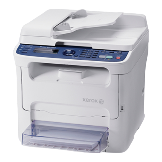
General Information Printer Introduction and Overview The Xerox Phaser 6121MFP combines a color laser print engine, scanner, copier, and Fax. The print engine uses a four-pass color laser architecture producing 20 page per minute (ppm) monochrome or 5 ppm color prints on Letter or A4 media. -
Page 25: Printer Configurations
General Information Printer Configurations The Phaser 6121MFP is available in three configurations. The 3-in-1 version connects to the host by USB and provides platen scan. The 4-in-1 versions are expandable with both the options Tray 2 and Duplex Unit to enable 2-sided printing. -
Page 26: Parts Of The Printer
Document Cover ADF (Auto Document Output Tray Feeder) Cover ADF Guides Tray 1 ADF Tray Tray 1 Dust Cover Document Stopper Front Door Printer Top Tray Extension Power Switch Control Panel USB Drive Port Document Glass Phaser 6121MFP Service Manual... -
Page 27: Rear View
Rear View s6121mfp-173 Item Description Power switch Power cord connection Fax Phone line out (Phaser 6121MFP/N and /D only) Line out jack (Phaser 6121MFP/N and /D only) USB cable port Network/Ethernet connections (Phaser 6121MFP/N and /D only) Phaser 6121MFP Service Manual... -
Page 28: Options
General Information Options Duplex Unit s6121mfp-175 Item Description Duplex Unit Optional Base Release Lever Duplex Unit Phaser 6121MFP Service Manual... - Page 29 General Information Lower Feeder Tray s6121mfp-176 Item Description Lower Feeder Unit 500-Sheet Feeder with Tray Cover Phaser 6121MFP Service Manual...
-
Page 30: Control Panel
On Hook before sending or Press to go to the System cancel current print/copy/ receiving disables the Menu, cancel an entered fax job. telephone extension. character, or return to the previous screen. Phaser 6121MFP Service Manual... -
Page 31: Maintenance Items
Print life figures are not guaranteed and varies depending on usage habits. Imaging Unit print life is based on 3-page jobs using letter-size paper. s6121mfp-172 Item Description Transfer Roller Fuser Imaging Unit Toner Cartridge Phaser 6121MFP Service Manual... -
Page 32: Consumables
Gray scale. Internal counters track consumables and maintenance life. Life ratings are based on A-size sheets at 5% coverage. Print Life Toner Cartridge C,M,Y Black Standard Capacity 1,500 pages 1,000 pages High Capacity 2,500 pages 2,500 pages 1-10 Phaser 6121MFP Service Manual... -
Page 33: Specifications
Thin card stock 1 (91 to 163 g/m2) Thick card stock 2 (164 to 209 g/m2) Postcards Envelopes Letterhead Label stock Tray capacities Plain paper and letterhead: 200 sheets Thick stock, postcards, labels, and glossy stock: 50 sheets Envelopes: 10 sheets Phaser 6121MFP Service Manual 1-11... -
Page 34: Performance Specifications
Copy resolution 600 x 600 dpi x 1 bit Scan speed Color: (Phaser 6121MFP/N or /D printer 600 x 600 dpi: 9.94 mm/second configurations only.) 600 x 300 dpi: 19.88 mm/second Monochrome: 600 x 600 dpi: 29.81 mm/second 600 x 300 dpi: 59.62 mm/second... -
Page 35: Controller
General Information Controller The following table lists controller functionality for the Phaser 6121MFP/S. Characteristic Description Memory RAM (128 MB) Flash ROM (4 MB for F/W) Interface USB 2.0 compliant Hard Disk Not supported Support Microsoft Windows Vista, Windows XP (Service Pack 2 or... -
Page 36: Electrical Specifications
-20 to 55° C (-4° to 131° F) Humidity (% RH) Operating 10 to 85% RH Storage 35 to 85% RH 0 to 2,500 meters (8,000 feet) Operating Altitude Acoustic Noise LWA(B) Sound Pressure (dBA) Printing Standby 1-14 Phaser 6121MFP Service Manual... -
Page 37: Media And Tray Specifications
Thin Card Stock (91 – 162 gsm / 30 – 60 lb. Cover) Thick Card Stock (164 – 209 gsm / 61 – 80 lb. Cover) Envelopes (DL and C6 sizes only) Labels Loading Capacity 200 sheets (20 lb.) Phaser 6121MFP Service Manual 1-15... -
Page 38: First Print Output Time (Fpot)
< 11 sec. < 28 sec. < 19 sec. Simplex A4/Letter < 33 sec. < 23 sec. < 33 sec. < 23 sec. N/A Duplex Legal Simplex < 33 sec. < 11 sec. Legal Duplex 1-16 Phaser 6121MFP Service Manual... -
Page 39: First Copy Output Time
FCOT (second) ADF Color 57.0 sec. 45.0 sec. Mono 23.0 sec. 19.0 sec. Physical Dimensions and Clearances Minimum Clearances Minimum clearances for the Phaser 6121MFP/S. 60.5 cm 71 cm (23.8 in.) (27.9 in.) 67.3 cm (26.5 in.) 27.8 cm (10.9 in.) 10 cm (3.9 in.) -
Page 40: Mounting Surface Specifications
General Information Minimum clearances for the Phaser 6121MFP/N 60.5 cm (23.8 in.) 81.4 cm (32.0 in.) 79.4 cm (31.3 in.) 10 cm 25.4 cm (3.9 in.) (10.0 in.) 10 cm (3.9 in.) s6121mfp-179 Mounting Surface Specifications These specifications apply to any printer used as a table-top printer. -
Page 41: Information Pages
Counter Information Shows usage data by job type. General Information Xerox Serial Number, Engine Serial Number, Installation Date, Engine Firmware, Boot Code, Controller Firmware, Language, Energy Saver Mode, Toner Low Prompt, Toner Out Action, Initial Mode, Size Mismatch, Tray type and size... - Page 42 General Information 1-20 Phaser 6121MFP Service Manual...
- Page 43 Theory of Operation In this chapter... • Operational Overview • Paper Path of the Printer • Major Assemblies and Functions • Media Handling Chapter...
-
Page 44: Operational Overview
Theory of Operation Operational Overview The Phaser 6121MFP is a full-color laser printer that utilizes electrophotographic recording principals to place a full color image onto the print media. The system contains a drum and developing unit that places the toner image of each color onto print media producing full-color prints. - Page 45 Transfer Belt to the media. 5. Paper Separation A Charge Neutralizing Cloth is provided on the guide plate to neutralize the charge. Charge Neutralizing Cloth Charge Neutralizing Cloth Transfer Belt 2nd Transfer Roller s6121mfp-105 Phaser 6121MFP Service Manual...
-
Page 46: System Control
Scanner TC/Y TC/M TC/C TC/K Control Panel Engine Control Board Paper Pick-Up/ Image Processor Board Transport Image Processing Image Process Fusing Power Supply/ High Voltage Laser Unit Image Bus Line Control System Line s6121mfp-280 Phaser 6121MFP Service Manual... -
Page 47: Paper Path Of The Printer
The print media is supplied from Tray 1 or the optional Tray 2, and is transported into the printer along the paper path as shown in the diagram. s6128mfp-107 Item Description Output Tray Tray 1 (MPT) Tray 2 (Optional 500-Sheet Feeder) Phaser 6121MFP Service Manual... -
Page 48: Automatic Document Feeder (Adf) Print Path
High. If the light is interrupted, the photo-transistor goes Low. Microswitches Microswitches are used primarily as cover interlocks. They are in a normally open state, and close when actuated. Microswitches employ hooks or catches for retention in the bracket or frame. Phaser 6121MFP Service Manual... - Page 49 Lower Feeder Unit and Duplex Unit. Error reporting is dependent on these designators. Error detection is based on paper transport timing through the sensing area. s6128mfp-108 Item Description Exit Sensor 2nd Image Transfer Retraction Position Sensor Registration Sensor Media Empty Sensor Phaser 6121MFP Service Manual...
- Page 50 Theory of Operation Automatic Document Feeder (ADF) Sensors s6121mfp-109 Description Item Paper Feed Sensor ADF Tray Phaser 6121MFP Service Manual...
-
Page 51: Major Assemblies And Functions
Major Assemblies and Functions The location of the system’s primary functional components is shown. Auto Document Feeder Scanner Fuser Imaging Unit Toner Cartridges Laser Unit Paper Feed Unit 1st Image Transfer Section 2nd Image Transfer Section s6121mfp-110 Phaser 6121MFP Service Manual... -
Page 52: Main Engine Component Overview
Theory of Operation Main Engine Component Overview Board Locations Scanner Control Board Fax Board Engine Control Board LVPS HVPS s6121mfp-360 2-10 Phaser 6121MFP Service Manual... - Page 53 Theory of Operation Sensors and Switches Front Door Switch Paper Feed Sensor Main Power Switch Exit Sensor Registration Sensor Paper Full Sensor 2nd Image Transfer Retraction/Position Sensor Registration Sensor Temperature/Humidity Sensor Rack Position Sensor Contact Switch s6121mfp-227 Phaser 6121MFP Service Manual 2-11...
- Page 54 Motors, Fans, and Solenoids LVPS Fan Exit Tray Cooling Fan Scanner Motor Cleaning Blade Pressure/ Retraction Solenoid 2nd Image Transfer Pressure/Retraction Solenoid Ozone Fan Conveyance Solenoid Main Motor Rack Motor Tray 1 Paper Feed Solenoid Developing Motor s6121mfp-361 2-12 Phaser 6121MFP Service Manual...
-
Page 55: Fuser
Theory of Operation Fuser Functional components of the Fuser appears below. Thermostat Exit Sensor (PS7) Thermistor (TH1) Pressure Roller Heater Lamp Fusing Roller s6121mfp-111 Fuser Drive The Fuser is driven by the Main Motor. s6121mfp-162 Phaser 6121MFP Service Manual 2-13... -
Page 56: Fuser Temperature Control
The main body leaves the power save mode. • A door is closed. Control Termination Timing • The Fuser roller reaches a predetermined temperature. • A malfunction or media misfeed is reset. • A door is opened. 2-14 Phaser 6121MFP Service Manual... -
Page 57: Wait Control
To ensure a good fixing level and light transmission performance, the fusing speed and Fuser Roller temperature are controlled. Control Start Timing A print request is received. Control Termination Timing A malfunction or media misfeed occurs. Phaser 6121MFP Service Manual 2-15... -
Page 58: Protection Against Abnormally High Temperature
OFF the relay to shut down each power supply line. Thermostat Protection If a faulty Thermistor (TH) prevents detection of abnormally high temperatures by soft protect or hard protect, the thermostat operates at a predetermined temperature to shut down the power supply line. 2-16 Phaser 6121MFP Service Manual... -
Page 59: Scanner
Functional components of the Scanner are illustrated below. Exposure Unit Scanner Motor (M101) s6121mfp-114 The Scanner does not include sensors for determining the size of the original document. Original media size settings are made on the Control Panel. Phaser 6121MFP Service Manual 2-17... - Page 60 It moves again to detect the reference position. • It moves to the stand-by position and stops there. Home Position (Stand-by Position) Original Reading Finish Position Reference Position Original Reading Scanner Stop Start Position Position Shading Original Reading Reference Position Detection s6121mfp-115 2-18 Phaser 6121MFP Service Manual...
- Page 61 • After it moves again to detect the reference position, it moves to the stand-by position and stops. Home Position (Stand-by Position) ADF Reading Reference Position Position Shading Original Reading Reference Position Detection s6121mfp-116 Phaser 6121MFP Service Manual 2-19...
-
Page 62: Laser Unit
Two lines are scanned through a single face of the polygon mirror. Photo Conductor Surface Beam A Beam B Photo Conductor G2 Lens Laser Diode G1 Lens Return Mirror Polygon Mirror s6121mfp-118 2-20 Phaser 6121MFP Service Manual... - Page 63 2. The four-sided polygon mirror rotates at high speeds driven by the Polygon Motor. 3. The Start-of-Scan (SOS) Sensor monitors laser light emission and initiates timing for each line of the scanning process. Photoconductor Semiconductor Laser SOS Board Polygon Motor s6121mfp-281 Phaser 6121MFP Service Manual 2-21...
- Page 64 The laser emission area is determined by the paper size. The area of 4 mm on both the leading and trailing edges of the paper is, however, the void image area. /HSYNC /VIDEO /TOD /VIDEO 4 mm 4 mm 4 mm 4 mm s6121mfp-119 2-22 Phaser 6121MFP Service Manual...
-
Page 65: Imaging Unit
When the Main Motor is energized, it turns the drive gear, which in turn rotates the drum. s6121mfp-123 The cleaning blade is pressed against the drum to remove excess toner. Waste toner is stored in the Imaging Unit. Phaser 6121MFP Service Manual 2-23... - Page 66 The life counter is reset when a new Imaging Unit is detected. When a predetermined number of printed pages are produced after the life value has been reached, the machine displays a Imaging Unit replacement message. 2-24 Phaser 6121MFP Service Manual...
-
Page 67: Toner Cartridge
3. Toner then sticks to the electrostatic latent image formed on the surface of the photo conductor drum. That part of toner left on the surface of the developing roller is returned to the toner supply portion. Phaser 6121MFP Service Manual 2-25... - Page 68 Bias Contact Point s6121mfp-283 Developer Roller Drive The Developer Roller is driven by the Developing Motor and intermediate gears. Intermediate Gear Developing Roller Developing Roller Drive Gear Developing Motor (M3) s6121mfp-128 2-26 Phaser 6121MFP Service Manual...
-
Page 69: Toner Cartridge Rack
• The cartridge replacement position refers to the position at which the Toner Cartridge Rack is stopped for replacement of the Toner Cartridge of a specific color of toner. Phaser 6121MFP Service Manual 2-27... - Page 70 The developing position is where the Toner Cartridge Rack is rotated 62° degrees from the standby position. 0° s6121mfp-132 The cartridge replacement position is where the Toner Cartridge Rack is rotated 90° degrees from the developing position. 90° s6121mfp-133 2-28 Phaser 6121MFP Service Manual...
- Page 71 6. Similarly, the Toner Cartridge Rack rotates and development of C is carried out, followed by K. 7. When the development of K is completed, the Toner Cartridge Rack rotates to the standby position. s6121mfp135 Phaser 6121MFP Service Manual 2-29...
- Page 72 When the Toner Cartridge Rack is rotated, the Rack Positioning Sensor (PS5) detects the standby position slit. To bring the toner cartridge rack to a stop at the corresponding developing position, the rack is rotated from the standby position 62° degrees by the Rack Motor. 2-30 Phaser 6121MFP Service Manual...
- Page 73 Developing Position Developing Position Developing Position s6121mfp-137 When a replacement request is made for a Toner Cartridge, the Toner Cartridge Rack is rotated 70 degrees from the depleted cartridges’ developing position by the Rack Motor. Phaser 6121MFP Service Manual 2-31...
-
Page 74: Transfer Belt
In addition to the Transfer Belt, a Transfer Roller (sometimes referred to as the 2nd Transfer Roller) transfers the composite image to the media for fusing. 2nd Transfer Roller Pressure Slider Pressure/Retraction Roller s6121mfp-284 2-32 Phaser 6121MFP Service Manual... - Page 75 The Transfer Belt and the 2nd Transfer Roller are driven by the Main Motor. The Transfer Roller Clutch at one end of the (2nd) Transfer Roller engages the Main Motor drive. Driven Roller Transfer Belt Imaging Unit Photoconductor Main Motor 1st Transfer Roller Transfer Belt Drive Roller s6121mfp-121 Phaser 6121MFP Service Manual 2-33...
- Page 76 Instead, the IDC sensor detects a sample image on the Transfer Belt to control the pressure/retraction operation. During monochrome printing, no retraction sequence is needed. The cleaning blade is normally in contact with the Transfer Belt. s6121mfp-139 2-34 Phaser 6121MFP Service Manual...
- Page 77 3. When the cleaning blade pressure/retraction solenoid (SD5) is energized, the half-moon-shaped pressure cam rotates a half turn to push the lever forward. 4. When the lever is pushed forward, the cleaning blade is retracted. s6121mfp-141 Item Description Cleaning Blade Pressure/Retraction Solenoid Lever Cleaning Blade Phaser 6121MFP Service Manual 2-35...
- Page 78 A. For a media sizes larger than A4, detection hole B is the reference for the image write start position. Belt Positioning Sensor Detection Hole B Detection Hole A s6121mfp-143 2-36 Phaser 6121MFP Service Manual...
-
Page 79: Transfer Roller
The Transfer Roller retraction operation is performed by the Main Motor, Image Transfer Solenoid, and Transfer Roller Clutch. When the Image Transfer Solenoid is energized, drive from the Main Motor is transmitted to the Transfer Roller Clutch. s6121mfp-144 Phaser 6121MFP Service Manual 2-37... -
Page 80: Image Transfer
4. When the Pressure Slider is moved, the ribs push against the Pressure Retraction Roller. 5. When the assembly is pushed up, the Transfer Roller presses against the Transfer Belt. 2nd Image Transfer Pressure/ Retraction Solenoid (SD4) 2nd Transfer Assembly Ribs Pressure Slider Pressure/Retraction Clutch s6121mfp-286 2-38 Phaser 6121MFP Service Manual... -
Page 81: Transfer Roller Cleaning
• Cover is opened and closed. • A media error occurs during a print cycle. • A paper empty condition occurs during a print cycle. • A paper size error occurs during a print cycle. Phaser 6121MFP Service Manual 2-39... -
Page 82: Process Control
ADC stabilizes image density to provide accurate tone reproduction. ADC uses the IDC Sensor and Temperature/Humidity Sensor to monitor system and environmental parameters to regulate the following: • Leak detection control For the clearance between the Drum and Developing Roller, an optimum 2-40 Phaser 6121MFP Service Manual... - Page 83 Sensor measures the density of the pattern and sends the measured result to the controller for gradation adjustment. ADC Sensor 1st Transfer Roller 2nd Transfer Roller Developing Charging Developing Bias Grid Bias ADC Control ATVC Temperature/ Humidity Sensor s6121mfp-147 Phaser 6121MFP Service Manual 2-41...
- Page 84 A new Imaging Unit or Toner Cartridge is detected. Mode 2 The Power Switch is turned Off and On, or Energy Saver mode is canceled after a predetermined number of printed pages have been produced. 2-42 Phaser 6121MFP Service Manual...
- Page 85 Control Of The Maximum Leak Detection Control Amount Of Toner Sticking Reflectance ADC Intensity Control Measurement Control Reflectance Laser Intensity Control Measurement Control Control Of The Maximum Amount Of Toner Sticking Laser Intensity Control G Correction Control s6121mfp-288 Phaser 6121MFP Service Manual 2-43...
-
Page 86: Temperature/Humidity Sensor
It is also used for image stabilization, transfer ATVC, and fusing temperature control. Note There is a Control Panel command which obtains environmental temperature and humidity levels. However, this command is for internal use only and not available from the service menus. s6121mfp-148 2-44 Phaser 6121MFP Service Manual... -
Page 87: System Thermal Regulation
Output Tray Fan Cools the Scanner and output media. Power Supply Fan Draws cool air across the Power Supply. Ventilation Fan Recovers toner powder in the Imaging Cartridge and exhausts the ozone produced to the outside. Phaser 6121MFP Service Manual 2-45... - Page 88 At the end of a print cycle (half-speed rotation following the predetermined period of time needed for full-speed rotation). • During standby. The Output Tray Fan stops when: • During Energy Saver mode. • During firmware upgrade. 2-46 Phaser 6121MFP Service Manual...
-
Page 89: Waste Toner Collection
Theory of Operation Waste Toner Collection Waste toner removed from the Transfer Belt and drum by the cleaning blade is transferred by two gear driven augers into the Imaging Unit waste toner reservoir. s6121mfp-150 Phaser 6121MFP Service Manual 2-47... - Page 90 Theory of Operation Waste Toner Collection Drive Waste toner collection augers are driven by the Main Motor. s6121mfp-151 2-48 Phaser 6121MFP Service Manual...
- Page 91 A waste toner full condition exists when 200 images are reached after a waste toner near full condition is detected. When the LED light is unblocked following Imaging Unit replacement, the waste toner full condition is reset. Phaser 6121MFP Service Manual 2-49...
-
Page 92: Media Handling
Theory of Operation Media Handling Tray 1 Feeder s6121mfp-153 2-50 Phaser 6121MFP Service Manual... - Page 93 Pick Roller via the Tray 1 Pick Clutch. At the same time, the Lift Cam is rotated, which raises the Lift Plate. The media is taken up and fed in by the Pick Roller. Pick Roller Main Motor (M1) Tray 1 Pick Solenoid (SD1) s6121mfp-154 s6121mfp-155 Phaser 6121MFP Service Manual 2-51...
- Page 94 To reduce the number of detected paper misfeeds, another feed sequence is carried out if a registration sensor signal transition fails to occur within a predetermined period of time. If after the second feed attempt media is not detected, a media empty/misfeed condition is reported. 2-52 Phaser 6121MFP Service Manual...
-
Page 95: Output Tray
Motor. During 1-sided printing, the exit roller rotates in the forward direction and feeds the media onto the output tray. If an optional Duplex Unit is attached, the exit roller is driven by the Duplex Unit. Phaser 6121MFP Service Manual 2-53... -
Page 96: Automatic Document Feeder (Adf)
Paper Exit Rollers s6121mfp-289 Automatic Document Feeder (ADF) The ADF feeds documents to the Scanner platen for scanning. The functional components within the ADF are illustrated below. Paper Feed Roller Document Feeder Transport Motor Pick-Up Roller s6121mfp-224 2-54 Phaser 6121MFP Service Manual... - Page 97 Multiple sheet feeding The coefficient of friction between the paper and separator pad is greater than that between sheets of paper. This ensures that only the first sheet of paper is transported by the media feed roller. Phaser 6121MFP Service Manual 2-55...
- Page 98 ADF Exit Operation The exit roller, driven by the ADF Transport Motor, turns to feed the original out of the ADF. The original is fed onto the output tray. Document Feeder Transport Motor (M100) Exit Roller s6121mfp-166 2-56 Phaser 6121MFP Service Manual...
-
Page 99: Duplex Unit
Duplex Unit. Cooling Fan Motor (FM3) Switchback Motor Door Sensor Transport Motor (M6) Transport Roller Transport Sensor AD Drive Board Registration Solenoid (SD7) Loop Sensor (PS13) Registration Roller s6121mfp-164 Transport Roller Registration Roller s6121mfp-163 Phaser 6121MFP Service Manual 2-57... - Page 100 Switchback Motor. This reverses the Exit Roller feeding the media into the Duplex Unit. s6121mfp-169 After entering the Duplex Unit, two Transport Rollers, driven by the Duplex Unit Transport Motor, move media through the system. s6121mfp-170 2-58 Phaser 6121MFP Service Manual...
- Page 101 8th page of the original on the fourth sheet of paper. The third sheet of paper waits at the Duplex take-up position until the fourth sheet of paper is subjected to a switchback sequence. The process repeats until the print job is complete. Phaser 6121MFP Service Manual 2-59...
-
Page 102: Duplex Unit Fan
The Duplex Unit Fan operates at full-speed at the start of a duplex operation, and then slows to half-speed after the duplex operation ends. The fan is off when the Duplex Unit is not in use. 2-60 Phaser 6121MFP Service Manual... -
Page 103: Sheet Feeder Unit (Tray)
It ensures that only one sheet of paper is fed in at time. The Pick Solenoid is controlled by the system through the PF Drive Board mounted in the feeder. Paper Empty Sensor (PS10) Coupling Gear Paper Feed Solenoid (SD6) s6121mfp-193 Phaser 6121MFP Service Manual 2-61... - Page 104 When media is present in the tray, the actuator is raised unblocking the sensor. When the tray is empty, the actuator drops into the slit in the Lift Plate blocking the sensor. PF Drive Board Paper Empty Sensor At Paper Empty Condition Under Normal Conditions s6121mfp-194 2-62 Phaser 6121MFP Service Manual...
- Page 105 The Tray Detect Switch signals the presence of a tray in the feeder. The switch is On when the tray is fully-inserted in the feeder. Lever Tray Set Detecting Switch Switch Actuator Tray 2 s6121mfp-195 Phaser 6121MFP Service Manual 2-63...
- Page 106 Theory of Operation 2-64 Phaser 6121MFP Service Manual...
- Page 107 Error Messages and Codes In this chapter... • Introduction • Error Messages • Jam Error Procedures • Service Call Error Troubleshooting Procedures Chapter...
-
Page 108: Introduction
OK > Stop/Reset > 0 > 0 > Stop/Reset > 0 > 1 2. Using the Down Arrow button, select Report and press OK. 3. Select Error Code List and press OK. The Error Code List is printed. Phaser 6121MFP Service Manual... - Page 109 Error Messages and Codes s6121mfp-372 Phaser 6121MFP Service Manual...
-
Page 110: Error Messages
Jam at Output tray Paper jam at Output tray. Open Top cover Original Doc. Jam Paper jam at the ADF. Open Doc. Feeder and clear the original. Reinsert original and press the Start key. Phaser 6121MFP Service Manual... -
Page 111: Service Call Messages
Turn power off, on 0310 Laser unit failure page 3-77 CODE (0310) Turn power off, on 0500 Fuser failure page 3-79 CODE (0500) Turn power off, on 0502 Thermistor failure page 3-80 CODE (0502) Turn power off, on Phaser 6121MFP Service Manual... - Page 112 Turn power off, on correct this error. 3C10 Eng. EEPROM failure Contact a Xerox CODE (3C10) representative to Turn power off, on correct this error. 3FFF Control ROM failure page 3-87 CODE (3FFF) Turn power off, on Phaser 6121MFP Service Manual...
-
Page 113: Scan Errors
The memory of the SMTP server has SMTP Server become full. 010F CANNOT GET IP The IP address of the server was not SMTP Server obtained from the DNS server. 0110 CANNOT GET IP POP3 Server 0111 CANNOT GET IP FTP Server Phaser 6121MFP Service Manual... - Page 114 Scan mode. 0114 COMMUNICATION ERROR FTP Server 0115 COMMUNICATION ERROR SMB Server 0118 DISCONNECT The connection to the server was SMTP Server interrupted. 0119 DISCONNECT POP3 Server 011B DISCONNECT FTP Proxy Server 011C DISCONNECT SMB Server Phaser 6121MFP Service Manual...
-
Page 115: Fax Errors
In phase C, no energy on line over 6 seconds before any corrected ECM frame. 001D Detected flag, but no signals after CFR. 0020 Cannot correct frame within 6 seconds or in no-ECM mode, one decoding line over 6 seconds. 0021 File full. Phaser 6121MFP Service Manual... - Page 116 Remote side disconnected after sending ANSam in V.8 phase. 0050 Correct signal not received after sending CJ signal in V.8 phase. 0051 Phase 3 signal not received within 20 seconds after phase 2 in V.34. 3-10 Phaser 6121MFP Service Manual...
- Page 117 Control channel signal not detected within 60 seconds after detect silence in phase D. 0066 T.30 signal or carrier not received after sending CFR in V.34. 0070 User pressed stop key when receiving. 0071 Memory full when receiving. 0072 Received EOR_Q Signal. Phaser 6121MFP Service Manual 3-11...
- Page 118 4. Boost the machine TX Level. Error code: 0016 Definition: Receive DCN signal after sending FTT signal. Solution: 1. Ask the sender to resend the fax. 2. Print out the protocol report, and provide it to Technical Support for analysis. 3-12 Phaser 6121MFP Service Manual...
- Page 119 2. Check the phone line for noise, and if necessary, replace the telephone line or contact your Telecom Service Provider. 3. Change the machine setting to ECM OFF, and then resend again. 4. Boost the TX Level of sender's machine. Phaser 6121MFP Service Manual 3-13...
- Page 120 1. Ask the sender to resend the fax. 2. Check the phone line for noise, and if necessary, replace the telephone line or contact your Telecom Service Provider. 3. Boost the TX Level of sender's machine. 4. Boost the machine TX Level.<*1>. 3-14 Phaser 6121MFP Service Manual...
- Page 121 2. Check the phone line for noise, and if necessary, replace the telephone line or contact your Telecom Service Provider. 3. Boost the TX Level of sender's machine. 4. Boost the machine TX Level.<*1>. 5. Print out the protocol report, and provide it to Technical Support for analysis. Phaser 6121MFP Service Manual 3-15...
- Page 122 1. Check the phone line for noise, and if necessary, replace the telephone line or contact your Telecom Service Provider. 2. Print out the protocol report, and provide it to Technical Support for analysis. 3. Boost the TX Level of sender's machine. 3-16 Phaser 6121MFP Service Manual...
- Page 123 3. Boost the TX Level of sender's machine. Error code: 0046 Definition: Receive incorrect signal when sending RNR which response with ERR signal. Solution: Print out the protocol report, and provide it to Technical Support for analysis. Phaser 6121MFP Service Manual 3-17...
- Page 124 2. Change the machine setting to ECM OFF, and then ask sender resend again. 3. Reduce the TX Level of sender's machine. 4. Print out the protocol report, and provide it to Technical Support for analysis. 3-18 Phaser 6121MFP Service Manual...
- Page 125 1. Check the phone line for noise, and if necessary, replace the telephone line or contact your Telecom Service Provider. 2. Change the machine setting to ECM OFF, and then ask sender resend again. 3. Print out the protocol report, and provide it to Technical Support for analysis. Phaser 6121MFP Service Manual 3-19...
- Page 126 1. Check the phone line for noise, and if necessary, replace the telephone line or contact your Telecom Service Provider. 2. Change the machine RX speed to V.17, and then ask sender resend again. 3. Print out the protocol report, and provide it to Technical Support for analysis. 3-20 Phaser 6121MFP Service Manual...
- Page 127 Telecom Service Provider. 2. Change the machine setting to ECM OFF, and then ask the sender to resend the fax. 3. Print out the protocol report, and provide it to Technical Support for analysis. Phaser 6121MFP Service Manual 3-21...
- Page 128 2. Check the phone line for noise, and if necessary, replace the telephone line or contact your Telecom Service Provider. 3. Boost the TX Level of sender's machine. 4. Print out the protocol report, and provide it to Technical Support for analysis. 3-22 Phaser 6121MFP Service Manual...
- Page 129 1. Check the phone line for noise, and if necessary, replace the telephone line or contact your Telecom Service Provider. 2. Boost the TX Level of sender's machine. 3. Print out the protocol report, and provide it to Technical Support for analysis. Phaser 6121MFP Service Manual 3-23...
- Page 130 4. Boost the TX Level of the sender's machine. 5. Print out the protocol report, and provide it to Technical Support for analysis. Error code: 0070 Definition: User pressed Stop key within receiving. Solution: Ask the sender to resend the fax. 3-24 Phaser 6121MFP Service Manual...
- Page 131 1. Check the phone line for noise, and if necessary, replace the telephone line or contact your Telecom Service Provider. 2. Reduce the TX Level of sender's machine. 3. Print out the protocol report, and provide it to Technical Support for analysis. Phaser 6121MFP Service Manual 3-25...
-
Page 132: Transmission Errors
Training attempt has failed because speed of the unit can not adjust to lower speed. 0088 Received DCN signal after sending out DCS signal. 008B Receiver’s protocol of DIS is received, but it is not compatible with this machine. 3-26 Phaser 6121MFP Service Manual... - Page 133 Cannot detect phase 5 signal within 30 seconds after phase 4. 00B8 Remote side disconnect after sending DCS signal in V.34. 00B9 Receive T.30 signal other than DIS, DCS, CFR after sending DCS signal in V.34. Phaser 6121MFP Service Manual 3-27...
- Page 134 Cannot detect any T.30 signal within 15 seconds during phase 4. 00DC Received T.30 signal in phase 4 other than DCS, DIS or DTC. 00DE Remote side no SUB capability in V.34. 00E0 At phase-D, transmitting PPS_NULL 3 times consecutively but receive no answer. 3-28 Phaser 6121MFP Service Manual...
- Page 135 At phase-D, transmitting EOR_EOM 3 times consecutively but receive no answer. 00F9 Received incorrect response after sending EOR_EOM. 00FA Received ERR signal after sending EOR_EOM. 00FB No response received in RR response procedure after sending EOR_EOM. 00FC No response received after sending CTC. Phaser 6121MFP Service Manual 3-29...
- Page 136 1. Check the phone line for noise, and if necessary, replace the telephone line or contact your Telecom Service Provider. 2. Boost the TX Level of sender's machine. 3. Print out the protocol report, and provide it to Technical Support for analysis. 3-30 Phaser 6121MFP Service Manual...
- Page 137 3. Adjust the SOFT SW12[6-7] to “11”, while receiving 4 PPR, the speed will down. 4. Change the machine TX speed to V.17, then resend again. 5. Print out the protocol report, and provide it to Technical Support for analysis. Phaser 6121MFP Service Manual 3-31...
- Page 138 1. Check the phone line for noise, and if necessary, replace the telephone line or contact your Telecom Service Provider. 2. Change the machine TX speed to V.17, then resend again. 3. Print out the protocol report, and provide it to Technical Support for analysis. 3-32 Phaser 6121MFP Service Manual...
- Page 139 1. Check the phone line for noise, and if necessary, replace the telephone line or contact your Telecom Service Provider. 2. Boost the TX Level of sender's machine. 3. Print out the protocol report, and provide it to Technical Support for analysis. Phaser 6121MFP Service Manual 3-33...
- Page 140 1. Check the phone line for noise, and if necessary, replace the telephone line or contact your Telecom Service Provider. 2. Boost the machine TX Level.<*1> 3. Print out the protocol report, and provide it to Technical Support for analysis. 3-34 Phaser 6121MFP Service Manual...
- Page 141 Telecom Service Provider. 2. Boost the machine TX Level.<*1> 3. Change the machine TX speed to V.17, and then resend. 4. Print out the protocol report, and provide it to Technical Support for analysis. Phaser 6121MFP Service Manual 3-35...
- Page 142 Telecom Service Provider. 2. Boost the machine TX Level.<*1> 3. Change the machine TX speed to V.17, and then resend. 4. Print out the protocol report, and provide it to Technical Support for analysis. 3-36 Phaser 6121MFP Service Manual...
- Page 143 Telecom Service Provider. 2. Boost the TX Level of sender's machine. 3. Change the machine TX speed to V.17, and then resend. 4. Print out the protocol report, and provide it to Technical Support for analysis. Phaser 6121MFP Service Manual 3-37...
- Page 144 1. Check the phone line for noise, and if necessary, replace the telephone line or contact your Telecom Service Provider. 2. Resend the fax. 3. Change the machine TX speed to V.17, and then resend. 4. Print out the protocol report, and provide it to Technical Support for analysis. 3-38 Phaser 6121MFP Service Manual...
- Page 145 Definition: After sending EOP signal, the received is not one of MCF, RTN, PIP, PIN, PRI-EOP, DCN. Solution: 1. Resend the fax 2. Print out the protocol report, and provide it to Technical Support for analysis. Phaser 6121MFP Service Manual 3-39...
- Page 146 2. Print out the protocol report, and provide it to Technical Support for analysis. Error code: 00D0 Definition: Received ERR signal after sending EOR_NULL. Solution: Print out the protocol report, and provide it to Technical Support for analysis. 3-40 Phaser 6121MFP Service Manual...
- Page 147 Telecom Service Provider. 2. Boost the machine TX Level.<*1> 3. Change the machine TX speed to V.17, and then resend. 4. Print out the protocol report, and provide it to Technical Support for analysis. Phaser 6121MFP Service Manual 3-41...
- Page 148 1. Check the phone line for noise, and if necessary, replace the telephone line or contact your Telecom Service Provider. 2. Boost the TX Level of sender's machine. 3. Boost the machine TX Level.<*1> 4. Print out the protocol report, and provide it to Technical Support for analysis. 3-42 Phaser 6121MFP Service Manual...
- Page 149 4. Print out the protocol report, and provide it to Technical Support for analysis. Error code: 00E5 Definition: Received incorrect response after sending PPS_MPS. Solution: 1. Resend the fax 2. Print out the protocol report, and provide it to Technical Support for analysis. Phaser 6121MFP Service Manual 3-43...
- Page 150 5. Print out the protocol report, and provide it to Technical Support for analysis. Error code: 00E9 Definition: Receive PIN signal after sent last page three times. Solution: Print out the protocol report, and provide it to Technical Support for analysis. 3-44 Phaser 6121MFP Service Manual...
- Page 151 2. Change the machine setting to ECM OFF, and then resend. 3. Boost the TX Level of sender's machine. 4. Boost the machine TX Level.<*1> 5. Print out the protocol report, and provide it to Technical Support for analysis. Phaser 6121MFP Service Manual 3-45...
- Page 152 2. Change the machine setting to ECM OFF, and then resend. 3. Boost the TX Level of sender's machine. 4. Boost the machine TX Level.<*1> 5. Print out the protocol report, and provide it to Technical Support for analysis. 3-46 Phaser 6121MFP Service Manual...
- Page 153 2. Change the machine setting to ECM OFF, then resend again. 3. Boost the TX Level of sender's machine. 4. Boost the machine TX Level.<*1> 5. Print out the protocol report, and provide it to Technical Support for analysis. Phaser 6121MFP Service Manual 3-47...
- Page 154 Error code: 00F9 Definition: Received incorrect response after sending EOR_EOM. Solution: 1. Change the machine setting to ECM OFF, and then resend. 2. Print out the protocol report, and provide it to Technical Support for analysis. 3-48 Phaser 6121MFP Service Manual...
- Page 155 4. Boost the machine TX Level.<*1> 5. Adjust the SOFT SW12[6-7] to “11”, while receiving 4 PPR, the speed will down. 6. Print out the protocol report, and provide it to Technical Support for analysis. Phaser 6121MFP Service Manual 3-49...
-
Page 156: Other Error/Warning Messages
The indicated toner cartridge(s) is at end of life and Replace CMYK toner should be replaced. Invalid Toner Indicates a non Xerox toner cartridge is installed. Replace with correct toner and press OK Imaging Unit life at The Imaging Unit is at end of life. - Page 157 An error occurred at the server. (Press any key) Incorrect password The password specified for xxxx server is incorrect. for xxxx Server Where xxxx can be SMTP, POP3, LDAP, FTP, or SMB. (Press any key) Phaser 6121MFP Service Manual 3-51...
- Page 158 Verify that the SMTP settings are correct. FTP is disabled The functionality is disabled. SMB is disabled The functionality is disabled. SMTP is disabled The functionality is disabled. Fax Comm Error A communication error occurred during the fax job. 3-52 Phaser 6121MFP Service Manual...
- Page 159 Address Book via USB. The error is generated if a USB memory. Address book file is not found on USB drive. Process error - Belt Open and close cover Process error - IDC Open and close cover Phaser 6121MFP Service Manual 3-53...
-
Page 160: Using The Troubleshooting Procedures
8. All voltage values given in the troubleshooting procedures are approximate values. The main purpose of voltage readings is to determine whether or not a component is receiving the correct voltage value from the power supply and if 3-54 Phaser 6121MFP Service Manual... - Page 161 12. Unless otherwise specified, the following voltage tolerances are used within this section: Stated Measured +3.3 VDC +3.135 to +3.465 VDC +5.0 VDC +4.75 to +5.25 VDC +24.0 VDC +21.6 to +26.4 VDC 0.0 VDC Less than +0.5 VDC Phaser 6121MFP Service Manual 3-55...
-
Page 162: Jam Error Procedures
You can move the printer to another location, or correct the environment that the printer operates in. 9. Cycle printer power, and if the problem persists, follow the troubleshooting procedure. 3-56 Phaser 6121MFP Service Manual... -
Page 163: Jam Errors
Duplex Unit page 3-66 Open top cover and section door duplex unit cover (Press any key) Jam at Duplex Unit Duplex in Duplex Unit page 3-67 Open Duplex cover transport door clear jammed paper section Phaser 6121MFP Service Manual 3-57... -
Page 164: Jam Error Procedures
Check the Engine Control Board Go to step 3. Reseat the connectors P/J10 and P/J12. connectors. If the Are the connectors seated problem persists, properly? go to step 3. 3-58 Phaser 6121MFP Service Manual... -
Page 165: Initial Actions
ON, a cover is opened and closed, or a misfeed or malfunction is reset. Applicable Error Code • Jam at Transfer Open top cover and remove Imaging Unit clear jammed paper close top cover Initial Actions Follow the directions in “Initial Actions for Jam Errors” on page 3-56. Phaser 6121MFP Service Manual 3-59... - Page 166 Replace the at P/J10-4, and at the same time print solenoid a page. (page 8-101). Is the solenoid operational? If the problem persists, go to step 5. Replace the Engine Control Board Complete. (page 8-59). 3-60 Phaser 6121MFP Service Manual...
- Page 167 Engine Control Board, PL13.0.20 Map 1 - Engine Control Board Plug/Jack Locator (page 10-5) Fuser, PL11.0.18 Map 2 - Image Processor Board Plug/Jack Locator (page 10-6) Power Supply Wiring (page 10-17) Imaging Wiring (page 10-15) Phaser 6121MFP Service Manual 3-61...
- Page 168 NOTE If you already replaced the fuser, go to step 5. Does the problem still persist? Replace the Image Processor Board Go to step 6. Complete. (page 8-66). Does the problem still persist? Replace the Engine Control Board Complete. (page 8-59). 3-62 Phaser 6121MFP Service Manual...
- Page 169 If Is the connector seated properly? the problem persists, go to step 2. Replace the Fuser (page 8-9). Go to step 3. Complete. Does the problem persist? Replace the Engine Control Board Complete. (page 8-59). Phaser 6121MFP Service Manual 3-63...
- Page 170 . To stop the Stop test, press the button. Check the Image Processor Board Go to step 4. Reseat the connectors P/J1 and P/J4. connectors. If Are the connectors seated properly? the problem persists, go to step 4. 3-64 Phaser 6121MFP Service Manual...
- Page 171 To avoid the potential of electric shock, ensure the power to the printer is off and the power cord is disconnected from the wall outlet prior to performing each step of the following troubleshooting procedure. Phaser 6121MFP Service Manual 3-65...
- Page 172 Duplex Switchback Motor has been energized for reverse drive. Applicable Error Code • Jam at Duplex Unit Open top cover and duplex unit cover Initial Actions Follow the directions in “Initial Actions for Jam Errors” on page 3-56. 3-66 Phaser 6121MFP Service Manual...
- Page 173 Applicable Error Code • Jam at Duplex Unit Open Duplex Unit cover clear jammed paper Initial Actions Follow the directions in “Initial Actions for Jam Errors” on page 3-56. Phaser 6121MFP Service Manual 3-67...
- Page 174 Go to step 4. Complete. actuator, and then replace the sensor. Does the problem persist? Replace the Duplex Unit (page 8-110). Go to step 5. Complete. Does the problem persist? Replace the Engine Control Board Complete. (page 8-59). 3-68 Phaser 6121MFP Service Manual...
-
Page 175: Service Call Error Troubleshooting Procedures
(page 8-79). If the problem persists, go to step 4. On the Engine Control Board, check Go to step 5. Go to step 6. P/J2 at pins 1, 5, and 7 for +24V. Are the voltages present? Phaser 6121MFP Service Manual 3-69... -
Page 176: B Toner Rack Failure
3. Check the Rack Positioning Sensor at Go to step 4. Replace the PJ5-11. sensor. If the Is the sensor on? problem persists, go to step 4. Replace the Engine Control Board Complete. (page 8-59). 3-70 Phaser 6121MFP Service Manual... -
Page 177: Scanner Fan Failure
Complete. (page 8-96). NOTE During replacement, check if the fan is obstructed and correct if necessary. If the problem persists, replace the fan. Does the problem persist? Replace the Image Processor Board Complete. (page 8-66). Phaser 6121MFP Service Manual 3-71... -
Page 178: A Duplex Unit Fan Failure
If Is the connector seated properly? the problem persists, go to step 2. Replace the Engine Control Board Go to step 3. Complete. (page 8-59). Does the problem persist? Replace the Duplex Unit. Complete. 3-72 Phaser 6121MFP Service Manual... -
Page 179: C Exhaust Fan Failure
+24 VDC at P/J2-1, 5, and 7. Check for Power Supply +5 VDC at P/J2-2. (page 8-72). If Are the voltages present and within the problem specification? persists, go to step 4. Replace the Engine Control Board Complete. (page 8-59). Phaser 6121MFP Service Manual 3-73... -
Page 180: E Lvps Fan Failure
Replace the Go to step 4. Motor control signals at PJ17 on the High Voltage Engine Control Board. Board Are the control signals operating (page 8-57). If correctly? the problem persists, go to step 4. 3-74 Phaser 6121MFP Service Manual... -
Page 181: Transfer Belt Failure
P/J9. connector. If Is the connector seated properly? the problem persists, go to step 2. Replace the Imaging Unit. Go to step 3. Complete. Does the problem persist? Replace the Engine Control Board. Complete. Phaser 6121MFP Service Manual 3-75... -
Page 182: Transfer Roll Failure
Does the problem persist? Check the 2nd Image Transfer Go to step 4. Reseat the Retraction Position Solenoid connector connector. If CN5. the problem Is the connector seated properly? persists, go to step 4. 3-76 Phaser 6121MFP Service Manual... -
Page 183: Laser Motor Failure And 0310 Laser Unit Failure
Applicable Parts Wiring and Plug/Jack References Laser Unit, PL4.0.13 Board Locations (page 2-10) Engine Control Board, PL13.0.20 Map 1 - Engine Control Board Plug/Jack Locator (page 10-5) Power Supply, PL13.0.17 Engine Control Board Wiring (page 10-14) Phaser 6121MFP Service Manual 3-77... - Page 184 +24V. (page 8-72). If Are the voltages present? the problem persists, go to step 4. Replace the Laser Unit. Go to step 3. Complete. Does the problem persist? Replace the Engine Control Board. Complete. 3-78 Phaser 6121MFP Service Manual...
-
Page 185: Fuser Failure And 0503 Thermistor Failure
2 > 6 > 2 > 3 > 7. Turn the printer off and then back on. Does the problem persist? Replace the Engine Control Board Go to step 4. Complete. (page 8-59). Does the problem persist? Replace the Power Supply (page 8-72). Complete. Phaser 6121MFP Service Manual 3-79... -
Page 186: Thermistor Failure, 0510 Fuser Failure, And 0520 Fuser Failure
Replace the Fuser (8-9). Go to step 5. Complete. Does the problem persist? Replace the Engine Control Board Go to step 6. Complete. (page 8-59). Does the problem persist? Replace the Power Supply (page 8-72). Complete. 3-80 Phaser 6121MFP Service Manual... -
Page 187: Scanner Home Failure
Replace the Scanner (page 8-31). Go to step 3. Complete. Does the problem persist? Replace the Engine Control Board Go to step 4. Complete. (page 8-59). Does the problem persist? Replace the Power Supply (page 8-72). Complete. Phaser 6121MFP Service Manual 3-81... -
Page 188: F51 Waste Toner Failure
Is the connector seated properly? the problem persists, go to step 3. Change the Imaging Unit (page 8-6). Go to step 3. Complete. Does the problem persist? Replace the Engine Control Board Complete. (page 8-59). 3-82 Phaser 6121MFP Service Manual... -
Page 189: Interface Failure
Are the connectors seated properly? persists, go to step 2. Replace the Image Processor Board Go to step 3. Complete. (page 8-66). Does the problem persist? Change the Engine Control Board Complete. (page 8-59). Phaser 6121MFP Service Manual 3-83... -
Page 190: C Fax Modem Failure
Power down and reboot the printer. Procedure Troubleshooting Reference Table Applicable Parts Wiring and Plug/Jack References Engine Control Board, PL13.0.20 Board Locations (page 2-10) Troubleshooting Procedure Table Step Action and Questions Replace the Engine Control Board Complete. (page 8-59). 3-84 Phaser 6121MFP Service Manual... -
Page 191: Dd Initial Toner Failure
The printer determines that an initial toner cartridge has been installed. The printer is programmed to only use initial toner cartridges one time. Initial Actions Install a Xerox Standard or High Capacity cartridge. For toner cartridge part numbers, see “Xerox Supplies and Accessories” on page 9-54. 13E2 Engine ROM Failure Flash ROM writing is found faulty during a check. -
Page 192: A3 Scanner Head Failure
If Are the connectors seated properly? the problem persists, go to step 2. Replace the Scanner (page 8-31). Go to step 3. Complete. Does the problem persist? Change the Image Processor Board Complete. (page 8-66). 3-86 Phaser 6121MFP Service Manual... -
Page 193: Fff Control Rom Failure
Complete. (page 8-59). Does the problem persist? Change the Image Processor Board Complete. (page 8-66). CF01 Controller Failure The printer determined that there is an NVRAM failure. Contact a Xerox representative to correct this error. Phaser 6121MFP Service Manual 3-87... - Page 194 Error Messages and Codes 3-88 Phaser 6121MFP Service Manual...
- Page 195 General Troubleshooting In this chapter... • Introduction • Servicing Instructions • Service Diagnostic Tests • General Printer Problems • 2-Sided Printing Problems • Media-Based Problems • Control Panel Troubleshooting • Fax Troubleshooting • Power Supply Problems • Abnormal Noise and Electrical Problems •...
- Page 196 “Print-Quality Problems Overview” on page 5-2. Caution Probable causes of trouble are that the printer, computer, server or other hardware is not correctly set for the network environment you are using, or a printer restriction has been exceeded. Phaser 6121MFP Service Manual...
-
Page 197: Servicing Instructions
1. Use the Parts List (page 9-1)to locate a part number. 2. Use the FRU Disassembly procedures to replace the part. Step 5: Final Checkout Test the printer to ensure you have corrected the initial problem and there are no additional problems present. Phaser 6121MFP Service Manual... -
Page 198: Service Diagnostic Tests
Stores a fax image in memory and provides a printed copy. • Scan Test Checks the lighting of the Exposure Lamp and the movement of the Scanner Unit. For instruction on using these tests, see “Functional Tests” on page 6-31. Phaser 6121MFP Service Manual... -
Page 199: General Printer Problems
The tray is out of Verify that at least paper. Tray 1 is loaded with paper, in place, and secure. There is a paper Clear the misfed misfeed or jam. paper. See “Jam Errors” on page 3-57. Phaser 6121MFP Service Manual... - Page 200 The paper tray is Verify that the tray is empty. loaded with paper. A document is Print the overlay file printed with an using a suitable overlay file which has printer driver. been created by an unsuitable printer driver. Phaser 6121MFP Service Manual...
- Page 201 For Booklet Left output is incorrect. driver and the Binding and Booklet application have Right Binding, choose been set for collation. Collate only in the printer driver’s Basic tab. Do not set collation in the application. Phaser 6121MFP Service Manual...
- Page 202 USB memory device that is used. You cannot enter Scan mode or An error has occurred Correct the cause of Fax mode. in Copy mode. the error and then select a different mode. Phaser 6121MFP Service Manual...
-
Page 203: Sided Printing Problems
6. Ensure that the media is a supported type for the tray. See “Media and Tray Specifications” on page 1-15, for the correct media types, sizes, and weights for each tray. 7. Load a fresh ream of paper in the tray. Phaser 6121MFP Service Manual... -
Page 204: Control Panel Troubleshooting
Control Panel LED is On, Control Panel Display is Blank 1. Remove and reseat the Image Processor Board connectors. 2. Replace the Control Panel (page 8-54). 3. Inspect and repair the Control Panel wiring harness. 4. Replace the Image Processor Board (page 8-66). 4-10 Phaser 6121MFP Service Manual... -
Page 205: Fax Troubleshooting
(CRP) (TSI) (NSS) (PWD) (SEP) (CIG) DTC (PWD) (SUB) (TSI) DCS (NSC) (CIG) DTC Mode setting from calling (TSI) DCS (PWD) (SEP) (CIG) terminal. (NSF) (CSI) DIS This is a poll operation. (CRP) (TSI) (NSS) Phaser 6121MFP Service Manual 4-11... - Page 206 PPS-EOM) or transmitter to the receiver. (RNR) (PPS-PRI-MPS) or (PPS-PRI-EOP) or (PPS-PRI-EOM) (CRP) (RR) Ask for the status of the (RNR) receiver: from the transmitter (ERR) to the receiver. (CRP) Phase E command. None 4-12 Phaser 6121MFP Service Manual...
-
Page 207: Transmission Fault
2. Did the Fax Protocol Report print out? Check the Go to step 3. latest TX result. If an error code is displayed, refer to the Transmission Errors list (page 3-26) for more information. Phaser 6121MFP Service Manual 4-13... - Page 208 Printer Can't Fax In VOIP System Environment Review the following information to determine why machine can't Fax properly in VOIP system environment. Troubleshooting Procedure Table Step Action and Questions Is Soft SW21[5]=”1”? Complete Set Soft SW21[5]=”1” 4-14 Phaser 6121MFP Service Manual...
- Page 209 Go to step 3. level? density level (Utility > Fax TX operation > Density level). The poor image quality may be caused Complete. by the RX machine. Confirm that the RX machine is working correctly. Phaser 6121MFP Service Manual 4-15...
-
Page 210: Reception Fault
(Call Waiting) may also cause image corruption. If copy function is faulty. Cause: Dirt or fault in printer. Corrective Action: Clean all parts of the printer or repair the printer. 4-16 Phaser 6121MFP Service Manual... - Page 211 Go to step 8. Have the properly at the sending machine? sender resend the fax. If the NOTE The poor image quality of received fax problem may be caused by the TX machine. persists, go to step 8. Phaser 6121MFP Service Manual 4-17...
- Page 212 Have the sender verify that the Complete. sending machine is set to a resolution appropriate for the document that is being transmitted. NOTE The poor image quality of received fax may be caused by the TX machine. 4-18 Phaser 6121MFP Service Manual...
-
Page 213: Other Fax Problems
VDSL (Very high Bit Rate Digital Subscriber Line) – An xDSL technology that provides faster data transmission over a single twisted pair of copper wires. VDSL transmits data from 13 Mbps ~ 55 Mbps over short distances, usually between 1000 and 4500 feet. Phaser 6121MFP Service Manual 4-19... - Page 214 Go to step 4. Complete. installation and reseat it. Is the problem still occurring? Replace the Fax Control Board. Have the input Complete. Is the problem still occurring? current from the phone line checked by a qualified professional. 4-20 Phaser 6121MFP Service Manual...
- Page 215 Go to step 3. handset on the hook. Check the Fax Control Board for correct Go to step 4. Complete. installation and reseat it. Is the problem still occurring? Replace the Fax Control Board. Complete. Phaser 6121MFP Service Manual 4-21...
-
Page 216: Fax Failure After Installation/Relocation
Manually dial any out-of-area phone Go to step 6. Check if the number. transmission Is there a connection? route consists of multiple telephone service providers. Confirm that your telephone line supports faxing. 4-22 Phaser 6121MFP Service Manual... - Page 217 Go to step 3. Receive a fax from another fax machine. Complete. Go to step Did the reception complete? Connect additional devices such as external telephone answering machine. Replace the Image Processor Board Complete. (page 8-66). Phaser 6121MFP Service Manual 4-23...
-
Page 218: Fax Failure After Continuous Normal Operation
Go to step 5. contract for the line type (Pulse to Tone, Line Type Tone to Pulse, etc.)? setting. Does the manual dialing function Go to step 6. Replace the properly? Image Processor Board (page 8-66). 4-24 Phaser 6121MFP Service Manual... - Page 219 Go to step and does the Fax job complete at the specified time? Is the Local Time setting correct? Go to step 11. Set the Local Time setting. Replace the Image Processor Board Complete. (page 8-66). Phaser 6121MFP Service Manual 4-25...
-
Page 220: Power Supply Problems
Check voltages at P/J2 on the Engine Replace the Replace the Control Board: 24 V (pins 1, 5, and 7), and Engine Power 5 V (pin 2). Control Supply Are all of the voltages present? Board. (page 8-72). 4-26 Phaser 6121MFP Service Manual... -
Page 221: Control Panel Indicators Do Not Light
If the problem persists, go to step 4. Is P/J10 on the Image Processor Board Go to step 5. Reseat the properly connected? connector. If the problem persists, go to step 5. Phaser 6121MFP Service Manual 4-27... -
Page 222: Abnormal Noise And Electrical Problems
10. Inspect the interior of the printer for damaged wires, loose connections, toner leakage, and damaged or obviously worn parts. 11. If the Print Cartridges appear obviously damaged, replace with new ones. 4-28 Phaser 6121MFP Service Manual... -
Page 223: Electrical Noise
If dirty, remove the High Voltage Board and clean it and the six springs. (page 8-57). Does the electrical noise still persist? Reseat the Imaging Unit and the Fuser. Complete. Phaser 6121MFP Service Manual 4-29... -
Page 224: Abnormal Noise During Standby
Troubleshooting Reference Table Applicable Parts Wiring and Plug/Jack Map References Power Supply (PL13.0.17) Map 5 - Power Supply Plug/Jack Locator (page 10-9) Troubleshooting Procedure Table Step Actions and Questions Replace the Power Supply (page 8-72). Complete. 4-30 Phaser 6121MFP Service Manual... -
Page 225: Operating System And Application Problems
Ports list is identical to the one on the Configuration page. You may need to click the Configure Port button to see the IP address. If necessary, re-select the TCP/IP number used for the printer. Phaser 6121MFP Service Manual 4-31... -
Page 226: Macintosh Troubleshooting (Mac Os 10.2 And Higher)
2. Open the Network Utility and click the Ping tab. 3. Enter the printer’s IP address. 4. Click Ping. If you do not get a response, verify that your TCP/IP settings are correct for your printer and computer. 4-32 Phaser 6121MFP Service Manual... -
Page 227: Troubleshooting
Print-Quality Troubleshooting In this chapter... • Print-Quality Problems Overview • Initial Actions for Troubleshooting Print-Quality • Print Quality Troubleshooting • Print-Quality Specifications Chapter... -
Page 228: Defects Associated With Specific Printer Components
Refer to “Media and Tray Specifications” on page 1-15 for supported and specialty media that have been tested and approved for use in the Phaser 6121MFP. Use paper from a fresh ream that is acclimated to room temperature and humidity. - Page 229 White or Colored Lines and Bands in Scan Direction (page 5-16) • Gradation Reproduction Failure (page 5-20) • Blurred Image (page 5-24) • Incorrect Color Image Registration (page 5-25) • Uneven Density in the Feed Direction (page 5-33) Phaser 6121MFP Service Manual...
-
Page 230: Repeating Defects
31 mm (1.22 in.) Rollers OPC Drum Rollers 74 mm (2.91 in.) IDT Rollers 132 mm (5.20 in.) Transfer Roller Transfer Roller 64 mm (2.52 in.) Fuser Heat Roller 83 mm (3.26 in.) Belt 94 mm (3.70 in.) Phaser 6121MFP Service Manual... -
Page 231: Initial Actions For Troubleshooting Print-Quality
A big temperature or humidity change has occurred. • The printer is restarted after settings have been changed. Normally you would not need to perform a calibration routine unless you are having problems with printing colors. Phaser 6121MFP Service Manual... -
Page 232: Environmental Checks
Relative humidity is 10 to 85%. If the printer is operating in an environment that is outside of these conditions, print quality can suffer. You can move the printer to another location, or correct the environment that the printer operates in. Phaser 6121MFP Service Manual... -
Page 233: Print Quality Troubleshooting
2. Press the Down Arrow button to navigate to Function, and then press OK. 3. Navigate to Prn Test Pattern, and then press OK. 4. Select a paper tray and press OK. 5. Select a test pattern, and then press OK. Phaser 6121MFP Service Manual... -
Page 234: Automatic Document Feeder (Adf) Print Quality Problems
Board, PL13.0.6 Blank Print Black Print Troubleshooting Procedure Table Step Actions and Questions Print Test Pattern 3 (see Go to step 6. Go to step 2. page 5-7). Does the defect occur on the printed output? Phaser 6121MFP Service Manual... - Page 235 Are the connectors seated properly? Replace the following Complete. units, listed in order, until problem is eliminated: Imaging Unit (page 8-6), High Voltage Board (page 8-57), Engine Control Board (page 8-59), and Laser Unit (page 8-50). Phaser 6121MFP Service Manual...
-
Page 236: Light Print
Does the defect still occur? Reseat all connectors and Replace the Scanner Complete. cables between the Unit (page 8-31). Scanner Unit and the Image Processor Board, and then make another copy. Does the defect still occur? 5-10 Phaser 6121MFP Service Manual... - Page 237 Toner Cartridge (page 8-20) Imaging Unit (page 8-6), Transfer Roller (page 8-56), Laser Unit (page 8-50), Engine Control Board (page 8-59), and High Voltage Board (page 8-57). Phaser 6121MFP Service Manual 5-11...
-
Page 238: Foggy Background
ADF from fully closing. If the ADF does not fully close, external light can produce background on the copy. Open and Close the ADF and verify it closes completely. Does the defect still occur? 5-12 Phaser 6121MFP Service Manual... - Page 239 If the problem window surface, and persists, go to step contact terminals connected properly? Has the problem been Complete. Replace the following eliminated? units until problem is eliminated: Laser Unit (page 8-50), Toner Cartridge (page 8-20). Phaser 6121MFP Service Manual 5-13...
-
Page 240: White Or Colored Lines And Bands In Feed Direction
The scanhead detects the foreign material while scanning, and the defect appears as streaks or spots on the copy output. Thoroughly clean the document glass. Does the defect still occur? 5-14 Phaser 6121MFP Service Manual... - Page 241 Inspect the Fuser. Clean the guide plate Go to step 10. Is the fusing entrance and reprint the test guide plate or the sheet. If the problem separation claw dirty or persists go to step 10. scratched? Phaser 6121MFP Service Manual 5-15...
-
Page 242: White Or Colored Lines And Bands In Scan Direction
Perform the initial actions listed on page 5-5. Troubleshooting Reference Table Applicable Parts Example Print Imaging Unit, PL4.0.13 Transfer Roller, PL7.1.10 Fuser, PL11.0.18 Laser Unit, PL4.0.2 Power Supply, PL13.0.17 Chrysanthemum x morifolium Chrysanthemum x morifolium Horizontal Band, Void, or Streaks Horizontal Stripes 5-16 Phaser 6121MFP Service Manual... - Page 243 Does the problem persist? Go to step 6. Complete. Is the developing bias Go to step 7. Clean the contact contact terminal of the terminal or reconnect toner cartridge connected the connector. If the properly? problem persists, go to step 7. Phaser 6121MFP Service Manual 5-17...
- Page 244 If the problem scratched? persists, replace the Fuser (page 8-9) and go to step 11. Has the problem been Complete. Replace the Power eliminated? Supply (page 8-72). 5-18 Phaser 6121MFP Service Manual...
-
Page 245: Black Spots
Does the defect still occur? Reseat all connectors and Replace the Scanner Complete. cables between the Unit (page 8-31). Scanner Unit and the Image Processor Board, and then make another copy. Does the defect still occur? Phaser 6121MFP Service Manual 5-19... -
Page 246: Gradation Reproduction Failure
Is the outside of the unit problem persists, go dirty? to step 3. Inspect the laser window. Carefully clean the Go to step 4. Is the outside of the surfaces. If the surface dirty? problem persists, go to step 4. 5-20 Phaser 6121MFP Service Manual... -
Page 247: Void Areas And White Spots
Step Actions and Questions Print Test Pattern 3 Replace the toner Go to step 2. (page 5-7). cartridge associated Is the error present in only with the defect. If the one color? defect persists, go to step 2. Phaser 6121MFP Service Manual 5-21... - Page 248 Are the green release release levers and go levers in the closed to step 6. position? Has the problem been Complete. Replace the toner eliminated? cartridge (page 8-20). If the problem persists, replace the Laser Unit (page 8-50). 5-22 Phaser 6121MFP Service Manual...
-
Page 249: Colored Spots
Replace the Fuser Go to step 6. Is the Fuser Roller dirty or (page 8-9). If the scratched? problem persists, go to step 6. Has the problem been Complete. Replace the toner eliminated? cartridge (page 8-20). Phaser 6121MFP Service Manual 5-23... -
Page 250: Blurred Image
If dirty? the problem persists, go to step 2. Has the problem been Complete. Replace the following eliminated? units, listed in order, until problem is eliminated: Imaging Unit (page 8-6), Laser Unit (page 8-50). 5-24 Phaser 6121MFP Service Manual... -
Page 251: Incorrect Color Image Registration
2. go to step 2. Has the problem been Complete. Replace the following eliminated? units, listed in order, until problem is eliminated: Engine Control Board (page 8-59), Laser Unit (page 8-50). Phaser 6121MFP Service Manual 5-25... -
Page 252: Poor Fusing Performance Or Offset
Close the levers. If the green fuser separator problem persists, go levers in the correct to step 3. position? Replace the following units, listed in order, until problem is eliminated: Engine Control Board (page 8-59), Fuser (page 8-9). 5-26 Phaser 6121MFP Service Manual... -
Page 253: Brush Effect Or Blurred Image
Does the problem persist? Inspect the Fuser. Clean the guide Go to step 4. Is the fusing entrance plate. guide plate dirty or If the problem scratched? persists go to step 4. Replace the Fuser (page 8-9). Phaser 6121MFP Service Manual 5-27... -
Page 254: Back Marking
4. Has the problem been Complete. Replace the following eliminated? units, listed in order, until the problem is eliminated: Imaging Unit (page 8-6), Fuser (page 8-9), High Voltage Board (page 8-57). 5-28 Phaser 6121MFP Service Manual... -
Page 255: Uneven Pitch
4. screw? Inspect the Imaging Unit. Replace the Imaging Go to step 5. Is the photo-conductor Unit (page 8-6). If surface dirty or scratched? the problem persists, go to step 5. Phaser 6121MFP Service Manual 5-29... - Page 256 7. Has the problem been Complete. Replace the following eliminated? units, listed in order, until problem is eliminated: Toner Cartridge (page 8-20), Imaging Unit (page 8-6). 5-30 Phaser 6121MFP Service Manual...
- Page 257 Remove the debris or Replace the ADF Unit and Pick Pad. replace the ADF Feed (page 8-39). Is there damage or debris Roller (page 8-14) on the Feed Roller or Pick and Pick Pad Pad? (page 8-18). Phaser 6121MFP Service Manual 5-31...
- Page 258 Go to step 12. Complete. Clean (page 7-5) or replace as necessary. Does the problem persist? Replace the Laser Unit Go to step 13. Complete. (page 8-50). Does the problem persist? Replace the Engine Control Board (page 8-59). 5-32 Phaser 6121MFP Service Manual...
-
Page 259: Uneven Density In The Feed Direction
4. Has the problem been Complete. Replace the following eliminated? units, listed in order, until problem is eliminated: Imaging Unit (page 8-6), Laser Unit (page 8-50), High Voltage Board (page 8-57). Phaser 6121MFP Service Manual 5-33... -
Page 260: Uneven Density In The Scan Direction
If the error persists, go to step 3. Has the problem been Complete. Replace the following eliminated? units, listed in order, until problem is eliminated: Imaging Unit (page 8-6), High Voltage Board (page 8-57). 5-34 Phaser 6121MFP Service Manual... -
Page 261: Print-Quality Specifications
180 mm ± 1.2 mm Vertical 234 mm ± 1.2 mm Linearity Scanning Direction Line Scanner 0.5 mm or less 0.5 mm or less Feeding Direction Line Scanner 0.7 mm or less 0.7 mm or less Phaser 6121MFP Service Manual 5-35... - Page 262 234 mm ± 0.8 mm Vertical Simplex 190 mm ± 0.5 mm Vertical Duplex 190 mm ± 0.8 mm Image Registration Leading Edge ± 2.5 mm (0.10 in.) Side Edge ± 2.0 mm (0.08 in.) 5-36 Phaser 6121MFP Service Manual...
- Page 263 Adjustments and Calibrations In this chapter... • Adjust Function Procedures • Service Mode • Maintenance Mode Chapter...
-
Page 264: Service Mode
3. Once you find the desired function, press the OK button again to enter the submenu or initiate the action. Note Pressing the Back/Menu at any level takes you up to the previous command level. Exiting Service Mode 1. Press Stop/Reset to exit. Phaser 6121MFP Service Manual... -
Page 265: Service Mode Menu Maps
Top Adjustment Postcard Left Adj. (Front) Envelope Left Adj. (Back) Label Simplex Pass Transfer Power Duplex Pass <*1> Plain Paper Image Adj Param Termperature Plain Paper Thick Supplies Replace Envelope BK Clear Fuser Transfer Roller s6121mfp-366 Phaser 6121MFP Service Manual... -
Page 266: Adjustments And Calibrations
T.30 Protocol List <*1> Relay Test <*1> Sensor Test <*1> Fixed Zoom Dial Test <*1> Change Volume Test <*1> Reduction2 Panel Speaker Test Reduction 1 RAM Test Expansion1 Clear Data Expansion2 SRAM Clear Memory Clear s6121mfp-367 Phaser 6121MFP Service Manual... -
Page 267: Service Mode Menu
The table below lists the menu options available from the Service mode menu. The table contains notations that have the following meanings: • <*1>: Displayed on Phaser 6121MFP/N/D. • <*2>: If the printer is a 220V model, this menu item doesn’t display. - Page 268 Cardstock Thick Cardstock Postcard Envelope Label Duplex Plain Paper page 6-24 Pass <*1> Image Adj Param page 6-25 Temperature Plain Paper page 6-26 Thick Envelope Supplies Replace Fuser page 6-27 Transfer Roller BK Clear page 6-27 Phaser 6121MFP Service Manual...
- Page 269 Scan To USB <*1> Twain Pictbridge <*1> USB TO Prn. <*1> Supplies Status C Toner page 6-29 M Toner Y Toner K Toner Imaging Unit CRU Usage Transfer Belt page 6-29 Fuser Transfer Roller Imaging Unit Phaser 6121MFP Service Manual...
- Page 270 6-41 Sensor Test <*1> page 6-41 Dial Test <*1> page 6-41 Volume Test <*1> page 6-41 Panel Speaker Test page 6-41 RAM Test page 6-41 Clear Data SRAM Clear page 6-42 Memory Clear page 6-42 Phaser 6121MFP Service Manual...
-
Page 271: Service's Choice Function Descriptions
V.29: 9600, 7200 • V.27: 4800, 2400 Send(TX) Level Sets PSK/FSK signal output level. Default Setting The default setting is -9 dBm. Available Settings -17 to -10 dBm, -9 dBm (default), or -8 to -2 dBm. Phaser 6121MFP Service Manual... -
Page 272: Default Setting
Calling tone output level. Default Setting The default setting is -11 dBm. Available Settings -17 to -2 dBm. CED Level Answer tone output level. Default Setting The default setting is -11 dBm. Available Settings -17 to -2 dBm. 6-10 Phaser 6121MFP Service Manual... -
Page 273: Available Settings
Fax number specifications: An up-to-20-digit number that may consist of [0-9], [*], [#], [pause], and [space] (0-9, #, *, pause, _). Default Setting The default setting is Off. Available Settings • On: Generate a report to report destination. • Off: No generate report. Phaser 6121MFP Service Manual 6-11... -
Page 274: Protocol Report
Specifies the time for GDI time out. Default Setting The default setting is 60 seconds. Available Settings • 5 Sec • 10 Sec • 20 Sec • 30 Sec • 40 Sec • 50 Sec • 60 Sec 6-12 Phaser 6121MFP Service Manual... - Page 275 Specifies whether or not a warning appears when either the toner or Imaging Unit is about to run out. Default Setting The default setting is On. Available Settings There is a On/Off setting for Toner Low and Imaging Unit Low. Phaser 6121MFP Service Manual 6-13...
-
Page 276: Adjustment Function Descriptions
Print Test Pattern 1 (page 6-32). Adjust the width of D in the copy of Test Pattern 1 so that the following specification is met 100 mm ± 0.5 mm (Zoom Ratio = Full Size:100%). Default Setting The default setting is 0%. Adjustment Range -2.0% to +2.0% in 0.2% increments. 6-14 Phaser 6121MFP Service Manual... - Page 277 Adjust the width of E in the copy of Test Pattern 1 so that the following specification is met: 200 mm ± 1 mm (Zoom Ratio = Full Size:100%). Default Setting The default setting is 0%. Adjustment Range -2.0% to +2.0% in 0.2% increments. Phaser 6121MFP Service Manual 6-15...
- Page 278 Adjust the widths A and B in the copy of TP1 so that the following specification is met: 0 mm ± 2.0 mm. Default Setting The default setting is 0 mm. Adjustment Range -5.0 mm to +5.0, in 0.5 mm increments. 6-16 Phaser 6121MFP Service Manual...
- Page 279 Note Perform after the Prn Main Regist adjustment has been performed. Adjustment Adjust the width of C in the printed Test Pattern 1 so that the following specification is met. Specification 20 ± 2.5 mm Phaser 6121MFP Service Manual 6-17...
- Page 280 If the width of C in the test pattern is longer than the specified width, increase the setting. • If the width of C in the test pattern is shorter than the specified width, decrease the setting. 6-18 Phaser 6121MFP Service Manual...
- Page 281 7. Using the Up and Down Arrow buttons, change the setting value and then press the OK button. 8. Place the test pattern into the Automatic Document Feeder. Then, make a test copy and recheck it. Phaser 6121MFP Service Manual 6-19...
- Page 282 1. Print Test Pattern 1 (page 6-32). 2. Enter the Adjustment menu in the service mode. 3. Select ADF Main Regist and press the OK button. 4. Place the test pattern into the Automatic Document Feeder and make a test copy. 6-20 Phaser 6121MFP Service Manual...
- Page 283 Position the test pattern vertically. Use A4 or Letter paper loaded into Tray 1 to make the test copy. 6. Check that the width of C in the copy of the test pattern is shifted. Phaser 6121MFP Service Manual 6-21...
-
Page 284: Top Adjustment
1. Select Top Adjustment and press the OK button. 2. Select the desired paper type and press the OK button. 3. Select desired adjustment amount with the Up and Down Arrow buttons, and the press the OK button. 6-22 Phaser 6121MFP Service Manual... - Page 285 1. Select Left Adj. (Back) and press the OK button. 2. Select desired tray and press the OK button. 3. Select desired adjustment amount with the Up and Down Arrow buttons, and then press the OK button. Phaser 6121MFP Service Manual 6-23...
- Page 286 Transfer Power (Duplex Pass) Function Adjusts the 2nd image transfer output (ATVC) on duplexed pages for each paper type. Use when the transfer failure at the trailing edge occurs. Adjustment Range -8 to +7 (default is 0). 6-24 Phaser 6121MFP Service Manual...
- Page 287 -100 V -200 V -300 V Procedure 1. Select Img Adjust Param and press the OK button. 2. Select the desired setting with the Up and Down Arrow buttons, and then press the OK button. Phaser 6121MFP Service Manual 6-25...
- Page 288 OK button. Adjustment Instructions If fusing performance is poor, increase the setting. If wax streaks occur, decrease the setting. If offset is poor, decrease the setting. If curling of the paper occurs, decrease the setting. 6-26 Phaser 6121MFP Service Manual...
- Page 289 Resets either the fuser counter or the transfer roller counter. Use when either the Fuser or the Transfer Roller has been replaced. Procedure 1. Select Supplies Replace and then either Fuser or Transfer Roller. 2. Press OK. 3. Press OK and reset the counter. Phaser 6121MFP Service Manual 6-27...
-
Page 290: Total Print
Displays the number of sheets of paper used for each tray. Paper Size Counter Displays the number of sheets of paper used for each size and type. Paper Type Counter Displays the number of sheets of paper used for each paper type. 6-28 Phaser 6121MFP Service Manual... -
Page 291: Supplies Status
Transfer Belt: Displays the remaining life of the transfer belt. Fuser: Displays the remaining life of the Fuser. Transfer Roller: Displays the remaining life of the transfer roller. Imaging Unit: Displays the remaining life of the drum unit. Phaser 6121MFP Service Manual 6-29... - Page 292 When the Image Processor Board has been replaced with a new one. Engine F/W Version Function Displays the version of the engine firmware. When the Engine Control Board has been replaced with a new one. 6-30 Phaser 6121MFP Service Manual...
- Page 293 When a paper misfeed occurs. Procedure 1. Select the paper tray. 2. Press OK to begin testing paper feeding. 3. Press Stop to stop testing paper feeding. Note Do not use this procedure when warming up the printer. Phaser 6121MFP Service Manual 6-31...
- Page 294 Pattern 1 Use If there is tilt or when registration or zoom ratio adjustments are performed. Pattern 1 Procedure 1. Select the paper tray. 2. Select Pattern1. 3. Press OK to print the test pattern. s6121mfp-333 6-32 Phaser 6121MFP Service Manual...
- Page 295 Pattern 2 Use When checking density and pitch irregularities, or when checking reproducibility of gradations. Pattern 2 Procedure 1. Select the paper tray. 2. Select Pattern2. 3. Press OK to print the test pattern. s6121mfp-334 Phaser 6121MFP Service Manual 6-33...
- Page 296 To print the test pattern for checking image density. Pattern 3 Use To check for density level consistency of all four toner cartridges. Pattern 3 Procedure 1. Select the paper tray. 2. Select Pattern3. 3. Press OK to print the test pattern. s6121mfp-373 6-34 Phaser 6121MFP Service Manual...
- Page 297 Procedure 1. Load A4S or LetterS paper into Tray1. 2. Select Function > Check Scan Window, and press OK. Two copy samples are fed out. 3. Check that no spots appear in the copy samples. Phaser 6121MFP Service Manual 6-35...
-
Page 298: Soft Switch
1. Select Function > Scan Test, and press OK. 2. Press the Stop key to stop the scanner test. Soft Switch Soft Switch Information unavailable. Used for internal development unless otherwise specified in troubleshooting procedures. 6-36 Phaser 6121MFP Service Manual... - Page 299 RX In Memory • Main RAM Size • ROM Id Retrieving the Service Data List 1. Enter the Service Mode. 2. Select Report and press OK. 3. Select Service Data List and press the Menu OK button. Phaser 6121MFP Service Manual 6-37...
- Page 300 Includes the following items: • Index: Index number from 0 - 9999 • Error: Error code number • Maker: NSF frame maker code • Tele.: Remote side or TX side telephone number for that transaction 6-38 Phaser 6121MFP Service Manual...
- Page 301 • DATA: T.30 frame that include address & control & Data Procedure 1. Enter the Service Mode. 2. Select Report and press the OK button. 3. Select T.30 Protocol List and press the OK button. Phaser 6121MFP Service Manual 6-39...
-
Page 302: Fixed Zoom Change
101% to 140% Expansion2 141% 141% to 199% Inch Values Setting name Initial zoom ratio Setting range Reduction2 51% to 64% Reduction1 65% to 99% Expansion1 129% 101% to 153% Expansion2 154% 154% to 199% 6-40 Phaser 6121MFP Service Manual... -
Page 303: Factory Test
Panel Speaker Test Checks the operation of the display and all indicators and buttons. When the panel buzzer test is finished, press the panel reset key twice. RAM Test Tests reading and writing of RAM memory. Phaser 6121MFP Service Manual 6-41... -
Page 304: Clear Data
• Some settings are not included in any reports or lists. Make a note of them separately. • After Memory Clear has been executed, make necessary entries of data again based on the recorded values. 6-42 Phaser 6121MFP Service Manual... -
Page 305: Maintenance Mode
Left Arrow key (for at least 2 seconds). 2. The window displays the following: Maintenance FAX Maintenance Adjustment 3. Press the Down Arrow button to locate all command lines in the displayed function tree. Exiting Press Stop to exit Maintenance Mode. Phaser 6121MFP Service Manual 6-43... - Page 306 Adjustments and Calibrations 6-44 Phaser 6121MFP Service Manual...
- Page 307 Cleaning and Maintenance In this chapter... • Maintenance Summary • Cleaning • Maintenance Procedures Chapter...
-
Page 308: Recommended Tools
7. Remove any debris or foreign objects from the Fuser, Transfer Belt, Imaging Unit, and inside of the printer. 8. Remove and clean the paper trays. 9. Clean all rubber rollers with a lint-free cloth slightly dampened with cold water. Phaser 6121MFP Service Manual... -
Page 309: Maintenance Procedures
Review proper printer operation using a customer file, if possible. Check with the customer regarding any special applications they are running. • Review with the customer all work that was performed and discuss proper printer care. Phaser 6121MFP Service Manual... -
Page 310: Clean The Scanner Glass
Cleaning and Maintenance Clean the Scanner Glass 1. Lift the scanner cover. 2. Clean the glass with a clean soft cloth. s6128mfp-030 Phaser 6121MFP Service Manual... -
Page 311: Feed Roller
Cleaning and Maintenance Feed Roller 1. Open the Top Cover. s6121mfp-021 2. Remove the Imaging Unit (page 8-6). Phaser 6121MFP Service Manual... - Page 312 Imaging Unit in a location where it is exposed to direct light (such as sunlight). 4. Using a soft cloth dampened with water, wipe any dirt or dust from the pick up roller. s6121mfp-307 Phaser 6121MFP Service Manual...
-
Page 313: Laser Window
2. Press the Down Arrow and select Replace Toner. 3. Press the Down Arrow and select Clean Laser Lens. 4. Follow the instructions on the control panel, and clean the Laser Unit window with a clean soft cloth. s6121mfp-308 Phaser 6121MFP Service Manual... -
Page 314: Adf Retard Roller And Feed Roller
Cleaning and Maintenance ADF Retard Roller and Feed Roller 1. Open the ADF Top Cover. s6121mfp-203 2. Wipe the Retard Roller and the Feed Roller clean of dirt using a soft cloth dampened with water. s6121mfp-309 Phaser 6121MFP Service Manual... - Page 315 Cleaning and Maintenance ADF Pick Pad 1. Open the ADF Top Cover. s6121mfp-203 2. Wipe the ADF Pick Pad clean of dirt using a soft cloth dampened with water. s6121mfp-310 Phaser 6121MFP Service Manual...
-
Page 316: Sheet Feeder Paper Pick-Up Roller
Cleaning and Maintenance 500-Sheet Feeder Paper Pick-up Roller 1. Lift the printer main body and then remove the 500-Sheet Feeder Unit from the printer. s6121mfp-293 7-10 Phaser 6121MFP Service Manual... - Page 317 Cleaning and Maintenance 2. Wipe the Paper Pick-up Roller clean of dirt using a soft cloth dampened with water. s6121mfp-294 Phaser 6121MFP Service Manual 7-11...
-
Page 318: Duplexer Transport Rollers
Cleaning and Maintenance Duplexer Transport Rollers 1. Open the duplex door. s6121mfp-031 7-12 Phaser 6121MFP Service Manual... - Page 319 Cleaning and Maintenance 2. Using a soft cloth dampened with water, wipe the transport rollers clean of dirt. s6121mfp-032 Phaser 6121MFP Service Manual 7-13...
- Page 320 This procedure is only valid if the Duplex Attachment is installed on the printer. 1. Lift the main printer body off of the Duplex Attachment (see page 7-10). 2. Using a soft cloth dampened with water, wipe the Duplex Attachment Feed Rollers clean of dirt. s6121mfp-305 7-14 Phaser 6121MFP Service Manual...
- Page 321 Service Parts Disassembly In this chapter... • Overview • Maintenance Items and Consumables • Covers • Disassembly Procedures • Electrical • Solenoids and Sensors • 500-Sheet Feeder Tray • Duplex Unit Chapter...
-
Page 322: Standard Orientation Of The Printer
When needed, the orientation of the printer is called out in the procedure as an aid for locating the printer parts. The following figure identifies the Front, Rear, Left, and Right sides of the printer. Left Rear Right Front s6121mfp-316 Phaser 6121MFP Service Manual... - Page 323 Parts List. For example, a part called Paper Tray in a removal procedure may appear on the Parts List as CASSETTE, ASSY. When working on a removal procedure, ignore any prerequisite procedure for parts already removed. Phaser 6121MFP Service Manual...
-
Page 324: Notations In The Disassembly Text
Bold arrows in an illustration show direction of movement when removing or replacing a component. • The notation “(tap, plastic, 10 mm)” or “(metal, 6 mm)” refer to the type of screw being removed. Replacement Note Provides information specific to the replacement of parts or assemblies. Phaser 6121MFP Service Manual... -
Page 325: Fastener Types
Always use the correct type and size screw. Using the wrong screw can damage tapped holes. Do not use excessive force to remove or install either a screw or a printer part. Phaser 6121MFP Service Manual... -
Page 326: Maintenance Items And Consumables
Service Parts Disassembly Maintenance Items and Consumables Maintenance items include the Imaging Unit, Fuser, and Feed Roller. Consumables consist of the four Toner Cartridges. Imaging Unit PL4.0.13 1. Lift the Top Cover. s6121mfp-021 Phaser 6121MFP Service Manual... - Page 327 Service Parts Disassembly 2. Remove the Imaging Unit. s6121mfp-197 Phaser 6121MFP Service Manual...
- Page 328 Keep the Imaging Unit horizontal and place it where it can not become dirty. Note Do not leave the Imaging Unit removed for more than 15 minutes, and do not place the removed Imaging Unit in a location where it is exposed to direct light (such as sunlight). Phaser 6121MFP Service Manual...
- Page 329 Service Parts Disassembly Fuser PL11.0.18 Warning Allow the Fuser to cool before servicing the printer. 1. Lift the Top Cover. s6121mfp-021 Phaser 6121MFP Service Manual...
- Page 330 2. Pull up the levers to unlock the fuser and then remove it. s6121mfp-198 Replacement Note If the Fuser being replaced has reached end-of-life: • Reset the Fuser counter in the service menu. • It is highly recommended that the Feed and Separator Rollers be replaced also. 8-10 Phaser 6121MFP Service Manual...
- Page 331 Service Parts Disassembly Feed Roller PL6.0.1 1. Open the Top Cover. s6121mfp-021 2. Remove the Imaging Unit (page 8-6). Phaser 6121MFP Service Manual 8-11...
-
Page 332: Separation Pad
Service Parts Disassembly 3. Remove the Feed Roller. s6121mfp-202 Separation Pad PL6.0.7 1. Remove the Lifting Plate Assembly (page 8-43). 2. Remove the Separation Pad. s6121mfp-336 3. Remove the spring and install it on the new pad. 8-12 Phaser 6121MFP Service Manual... -
Page 333: Adf Pick-Up Roller
Service Parts Disassembly ADF Pick-up Roller PL1.1.3 1. Open the ADF Top Cover. s6121mfp-203 2. Unsnap the 2 clips on the ADF Pick-up Roller shaft. s6121mfp-368 Phaser 6121MFP Service Manual 8-13... -
Page 334: Adf Feed Roller
Service Parts Disassembly 3. Unsnap the ADF Pick-up Roller shaft from the assembly, and remove the roller from the shaft. s6121mfp-369 ADF Feed Roller PL1.1.4 1. Open the ADF Top Cover. s6121mfp-203 8-14 Phaser 6121MFP Service Manual... - Page 335 Service Parts Disassembly 2. Remove the C-ring from the end of the shaft and remove the gear assembly. s6121mfp-345 Phaser 6121MFP Service Manual 8-15...
- Page 336 Service Parts Disassembly 3. Pull up on the bushing tab and rotate the bushing clockwise until you can pull the bushing off of the shaft. s6121mfp-346 8-16 Phaser 6121MFP Service Manual...
- Page 337 4. Remove 2 C-clips as shown. s6121mfp-347 5. Slide the roller and gears in the direction of the arrow. s6121mfp-348 6. Rotate the shaft until you can see the pin sticking through the shaft. 7. Carefully remove the pin. Phaser 6121MFP Service Manual 8-17...
- Page 338 Service Parts Disassembly 8. Slide the shaft out of the ADF Top Cover until you can remove the ADF Feed Roller. s6121mfp-354 ADF Pick Pad PL1.2.9 1. Open the ADF Top Cover. s6121mfp-203 8-18 Phaser 6121MFP Service Manual...
- Page 339 Service Parts Disassembly 2. Squeeze the tabs on the ADF Pick Pad and remove it. s6121mfp-204 Phaser 6121MFP Service Manual 8-19...
-
Page 340: Toner Cartridges
3. Press the Down arrow button and select Toner Change. 4. Select the toner cartridge that you want to replace and press OK. 5. Open the Front Cover. s6121mfp-196 6. Hold onto the handle, pull it and remove the Toner Cartridge. s6121mfp-023 8-20 Phaser 6121MFP Service Manual... - Page 341 Service Parts Disassembly 7. Shake the cartridge a few times to distribute the toner. s6121mfp-312 Note Do not tip the toner cartridge to a vertical position. s6121mfp-311 Phaser 6121MFP Service Manual 8-21...
- Page 342 9. Aligning the shaft on both sides of the Toner Cartridge with the rails in the machine, install the cartridge. s6121mfp-314 10. Press down on the Toner Cartridge until it snaps into place. s6121mfp-315 11. Close the Front Cover and press the Stop button. 8-22 Phaser 6121MFP Service Manual...
- Page 343 Service Parts Disassembly Replacing Toner Cartridges Manually Use this procedure to replace toner cartridges when the printer is turned off. 1. Open Front Cover. s6121mfp-196 Phaser 6121MFP Service Manual 8-23...
- Page 344 2. Press and hold the rack release lever, and then rotate the rack until the toner cartridge is easily removed. Caution When rotating the rack, do not touch the Developing Rollers. Rack Release Lever s6121mfp-238 8-24 Phaser 6121MFP Service Manual...
- Page 345 Service Parts Disassembly 3. Hold onto the handle, pull it and remove the Toner Cartridge. s6121mfp-023 Phaser 6121MFP Service Manual 8-25...
- Page 346 Service Parts Disassembly 4. Shake the cartridge a few times to distribute the toner. s6121mfp-312 Note Do not tip the toner cartridge to a vertical position. s6121mfp-311 8-26 Phaser 6121MFP Service Manual...
- Page 347 6. Aligning the shaft on both sides of the Toner Cartridge with the rails in the machine, install the cartridge. s6121mfp-314 7. Press down on the Toner Cartridge until it snaps into place. s6121mfp-315 8. Close the Front Cover. Phaser 6121MFP Service Manual 8-27...
-
Page 348: Rear Cover
PL3.0.15 1. Remove 5 screws (metal, 8mm) that secure the rear cover. s6121mfp-001 Left Side Cover PL 3.0.12 1. Remove the rear cover (page 8-28). 2. Open the top cover. 3. Open the front cover. 8-28 Phaser 6121MFP Service Manual... -
Page 349: Right Side Cover
Service Parts Disassembly 4. Remove 2 screws (metal, 10 mm) that secure the left side cover. s6121mfp-002 Right Side Cover PL 3.0.1 1. Open the top cover. 2. Open the front cover. Phaser 6121MFP Service Manual 8-29... -
Page 350: Adf Rear Cover
ADF Rear Cover PL 1.1.5 1. Open the ADF top cover. 2. Remove 1 screw (silver, tap, 10 mm), and squeeze the ADF top cover to unhook the 2 tabs that secure it. s6121mfp-008 8-30 Phaser 6121MFP Service Manual... -
Page 351: Disassembly Procedures
4. On the Image Processor Board, disconnect the 2 flat cables at P/J6 and P/J7, and release them from the cable guide. P/J2 P/J1 P/J4 P/J6 P/J7 s6121mfp-207 5. Remove the cables from P/J1. P/J2, and P/J4, and unthread them from the harness guide. Phaser 6121MFP Service Manual 8-31... - Page 352 Service Parts Disassembly 6. On the Engine Control Board, remove connector PJ24 and remove the harness from the harness guide. P/J24 s6121mfp-208 8-32 Phaser 6121MFP Service Manual...
- Page 353 Service Parts Disassembly 7. Remove the screw (metal, 6mm), and remove the harness band. s6121mfp-209 8. On the right side of the printer, remove the ground wire screw (metal, 6mm, with lock washer and flat washer). s6121mfp-009 Phaser 6121MFP Service Manual 8-33...
- Page 354 Service Parts Disassembly 9. Remove the e-ring s6121mfp-211 10. Remove the arm and the spring from the notch on the plate. s6121mfp-210 8-34 Phaser 6121MFP Service Manual...
- Page 355 Service Parts Disassembly 11. Remove the screw (metal, 6mm) and the stopper. s6121mfp-212 Phaser 6121MFP Service Manual 8-35...
- Page 356 Service Parts Disassembly 12. On the left side of the printer, remove the e-ring and the arm, and then remove the spring from the notch on the plate. s6121mfp-213 8-36 Phaser 6121MFP Service Manual...
- Page 357 Service Parts Disassembly 13. Remove the screw (metal, 6mm) and the stopper. s6121mfp-215 14. Remove the Upper Rear Cover. s6121mfp-337 Phaser 6121MFP Service Manual 8-37...
- Page 358 16. Unlace the harnesses from the guide Note Note the orientation of the harnesses through the guide. 17. Lift the Scanner slightly, and then unhook the tab and remove the second harness guide as shown below. s6121mfp-015 8-38 Phaser 6121MFP Service Manual...
-
Page 359: Adf Unit
When replacing the scanner, you must transfer the following parts from the old assembly to the new scanner before reinstallation: • • Spring Mechanism • Exit Chute ADF Unit PL1.1.6 1. Remove the scanner unit (page 8-31). 2. Remove 2 screws (silver, tap, 10 mm). s6121mfp-217 Phaser 6121MFP Service Manual 8-39... - Page 360 Service Parts Disassembly 3. Remove the harnesses from the harness guide. s6121mfp-356 4. Remove the screw (metal, 8mm) and remove the arm unit. s6121mfp-338 5. Repeat step 4 to remove the arm unit on the opposite side. 8-40 Phaser 6121MFP Service Manual...
- Page 361 Service Parts Disassembly 6. Remove 6 screws (metal, 8mm) and remove the Scanner Unit Lower Cover Assembly. s6121mfp-339 Phaser 6121MFP Service Manual 8-41...
- Page 362 Service Parts Disassembly 7. Remove the clamp from the Sensor Harness. s6121mfp-355 8. Pull the harnesses through the scanner unit and remove the ADF. 8-42 Phaser 6121MFP Service Manual...
-
Page 363: Lifting Plate Assembly
1. Remove the Rear Side Cover (page 8-28). 2. Remove the Left Side Cover (page 8-28). 3. Remove the Right Side Cover (page 8-29). 4. Remove the Scanner (page 8-31). 5. Lay the printer on its rear side. s6121mfp-218 Phaser 6121MFP Service Manual 8-43... - Page 364 Service Parts Disassembly 6. Remove 4 screws (metal, 6mm) and remove the bottom plate. Note Be careful to not lose the Lifting Plate springs. s6121mfp-219 8-44 Phaser 6121MFP Service Manual...
- Page 365 Service Parts Disassembly 7. Remove 2 screws (metal, 8mm) and remove the Lifting Plate Assembly. s6121mfp-188 Phaser 6121MFP Service Manual 8-45...
- Page 366 3. Remove the Right Side Cover (page 8-29). 4. Remove the Scanner (page 8-31). 5. Remove the Lifting Plate Assembly (page 8-43). 6. Remove the 2 pieces of tape. s6121mfp-190 7. Disconnect the Feed Solenoid CN2 connector. s6121mfp-189 8-46 Phaser 6121MFP Service Manual...
- Page 367 Service Parts Disassembly 8. Disconnect CN1 on the High Voltage Board, and guide the harness through the printer frame and through the frame on the opposite side. s6121mfp-317 Phaser 6121MFP Service Manual 8-47...
- Page 368 Service Parts Disassembly 9. Remove 4 screws (one metal, 6mm, and three metal, 8mm). 2 screws are located on each side of the printer. 8 mm s6121mfp-221 8 mm 6 mm s6121mfp-222 8-48 Phaser 6121MFP Service Manual...
- Page 369 Service Parts Disassembly 10. Remove the Feeder. Note You may have to gently flex the printer frame to remove the feeder. s6121mfp-357 Phaser 6121MFP Service Manual 8-49...
- Page 370 3. Remove the Left Side Cover (page 8-28). 4. Remove the Right Side Cover (page 8-29). 5. Remove the High Voltage Board (page 8-57). 6. Remove the Toner Cartridges (page 8-20). 7. Disconnect P/J8 from the Image Processor Board. P/J8 s6121mfp-223 8-50 Phaser 6121MFP Service Manual...
- Page 371 Service Parts Disassembly 8. Disconnect P/J18 and P/J19 from the Engine Control Board. P/J18 P/J19 s6121mfp-239 Phaser 6121MFP Service Manual 8-51...
- Page 372 Service Parts Disassembly 9. Remove the screw (metal, 8mm), and then remove the guide. s6121mfp-323 10. Remove 2 screws (metal, 8mm). s6121mfp-324 11. Remove a toner cartridge. 8-52 Phaser 6121MFP Service Manual...
- Page 373 12. Press and hold the rack release lever, and then rotate the rack until you have access to the screw shown in the next step. Caution When rotating the rack, do not touch the Developing Rollers. Rack Release Lever s6121mfp-238 Phaser 6121MFP Service Manual 8-53...
- Page 374 Service Parts Disassembly 13. Remove the screw (metal, 8mm) and then remove the Laser Unit. s6121mfp-325 Electrical Control Panel PL2.0.5 1. Gently lift the control panel bezel. s6121mfp-011 8-54 Phaser 6121MFP Service Manual...
- Page 375 Service Parts Disassembly 2. Remove 3 screws (silver, tap, 10 mm) that secure the control panel. s6121mfp-012 3. Disconnect CN701 from the Control Panel. s6121mfp-013 Phaser 6121MFP Service Manual 8-55...
- Page 376 Transfer Roller PL7.1.10 1. Remove the Imaging Unit (page 8-6). 2. Remove the Transfer Roller by squeezing the white tabs of the holders located on both sides, and then pull out the roller. Transfer Roller s6121mfp-230 8-56 Phaser 6121MFP Service Manual...
-
Page 377: High Voltage Board
2. It is highly recommended that the Feed and Separator Rollers be replaced also. High Voltage Board PL13.0.6 1. Remove the Right Cover (page 8-29). 2. Disconnect three connectors (CN1, CN2, and T2) from the High Voltage Board. Phaser 6121MFP Service Manual 8-57... - Page 378 1. Ensure that the board is installed underneath all four tabs. See step 4. 2. Use the correct screws on each side of the board (on the left use two 6mm screws, on the right use two 8mm screws). 8-58 Phaser 6121MFP Service Manual...
-
Page 379: Engine Control Board
Service Parts Disassembly Engine Control Board PL13.0.20 1. Remove the Rear Cover (page 8-28). 2. Remove the Left Side Cover (page 8-28). 3. Disconnect all connectors on the Engine Control Board. s6121mfp-007 Phaser 6121MFP Service Manual 8-59... - Page 380 Service Parts Disassembly 4. Remove 4 screws (metal, 6mm) and remove the Engine Control Board. s6121mfp-233 8-60 Phaser 6121MFP Service Manual...
- Page 381 Remove the chip from the old Engine Control Board, and mount it on the new Engine Control Board. NVRAM s6121mfp-234 Align the notch on the chip with the notch in the socket. Notch Notch s6121mfp-171 Phaser 6121MFP Service Manual 8-61...
-
Page 382: Fax Board
Service Parts Disassembly Fax Board 13.0.30 1. Remove the Rear Cover (page 8-28). 2. Remove the Right Side Cover (page 8-29). 3. Disconnect connector P/J1 on the Fax Board. P/J1 s6121mfp-240 8-62 Phaser 6121MFP Service Manual... - Page 383 Service Parts Disassembly 4. Unhook the tab and remove the harness guide. s6121mfp-242 Phaser 6121MFP Service Manual 8-63...
- Page 384 Service Parts Disassembly 5. Disconnect P/J6 and P/J7 on the Image Processor Board. P/J6 P/J7 s6121mfp-241 8-64 Phaser 6121MFP Service Manual...
- Page 385 Service Parts Disassembly 6. Remove 4 screws (metal, 6mm) and remove the Fax Board. s6121mfp-243 Phaser 6121MFP Service Manual 8-65...
-
Page 386: Image Processor Board
3. Remove the Engine Control Board (page 8-59). 4. Remove the Fax Board (page 8-62). 5. Remove 2 screws (metal, 6mm) and remove the bracket. s6121mfp-247 6. Disconnect all connectors from the Image Processor Board. P/J9 P/J10 s6121mfp-248 8-66 Phaser 6121MFP Service Manual... - Page 387 Service Parts Disassembly 7. Remove the screw (metal, 6mm, flangeless) from the USB connector. s6121mfp-251 Phaser 6121MFP Service Manual 8-67...
- Page 388 Service Parts Disassembly 8. Remove 2 screws (metal, 6mm) and remove the bracket. s6121mfp-249 9. Remove the 4 remaining screws (metal, 6mm) and remove the board. s6121mfp-252 8-68 Phaser 6121MFP Service Manual...
- Page 389 Replacement Note For the Phaser 6121MFP/N and /D, boot data is written to the Image Processor Board, and firmware data is written to the Fax Board. To avoid problems, replace the Image Processor Board and Fax Board at the same time.
-
Page 390: Usb Board
Service Parts Disassembly USB Board PL13.0.8 1. Remove the Rear Cover (page 8-28). 2. Remove the Right Side Cover (page 8-29). 3. Remove the Fax Board (page 8-62). 4. Disconnect CN1 from the Image Processor Board. s6121mfp-245 8-70 Phaser 6121MFP Service Manual... - Page 391 Service Parts Disassembly 5. Remove the harness from the 2 wire saddles. s6121mfp-235 6. Remove 2 screws (metal, 6mm) and remove the USB Board. s6121mfp-236 Phaser 6121MFP Service Manual 8-71...
-
Page 392: Power Supply
3. Remove the Right Side Cover (page 8-29). 4. Remove the Engine Control Board (page 8-59). 5. Remove the Image Processor Board (page 8-66). 6. Disconnect the Front Door Switch connectors CN11 and CN12. CN11 CN12 s6121mfp-342 8-72 Phaser 6121MFP Service Manual... - Page 393 Service Parts Disassembly 7. Open the wire guides and unlace the Front Door Switch wires from the guides. s6121mfp-237 8. Remove 2 screws (metal, 6mm, with lock washer and washer) from the power switch. s6121mfp-327 Phaser 6121MFP Service Manual 8-73...
- Page 394 Service Parts Disassembly 9. Disconnect connectors CN9, CN10 from the power switch. s6121mfp-349 8-74 Phaser 6121MFP Service Manual...
- Page 395 Service Parts Disassembly 10. Disconnect connector CN13. s6121mfp-350 Phaser 6121MFP Service Manual 8-75...
- Page 396 Service Parts Disassembly 11. Remove 2 screws (metal, 6mm, with lock washer and washer) and remove plate. s6121mfp-250 12. Remove the harnesses and the harness guide. s6121mfp-246 8-76 Phaser 6121MFP Service Manual...
- Page 397 Service Parts Disassembly 13. Remove the screw (metal, 6mm) and remove the harness band. s6121mfp-351 Phaser 6121MFP Service Manual 8-77...
- Page 398 Service Parts Disassembly 14. Remove 4 screws (metal, 6mm, with lock washer and flat washer) and 1 screw (metal, 8mm) and pull out the power supply unit. s6128mfp-260 s6121mfp-261 8-78 Phaser 6121MFP Service Manual...
-
Page 399: Main Motor
1. Remove the Right Side Cover (page 8-29). 2. Disconnect connector CN8 and remove 2 screws (metal, 6mm) to remove the speaker. s6121mfp-006 Main Motor PL9.1.6 1. Remove the Left Cover (page 8-28). 2. Remove all toner cartridges (page 8-20). Phaser 6121MFP Service Manual 8-79... - Page 400 Service Parts Disassembly 3. Remove the harness from 2 wire saddles. s6121mfp-271 4. Remove 3 screws (metal, 6mm, with washer and lock washer) and remove the cover plate. s6121mfp-272 8-80 Phaser 6121MFP Service Manual...
- Page 401 Service Parts Disassembly 5. Remove 3 screws (metal, 6mm, with washer and lock washer), and then remove the harness from the harness guide. s6121mfp-352 6. Unlock the motor cover tab. s6121mfp-358 Phaser 6121MFP Service Manual 8-81...
- Page 402 Service Parts Disassembly 7. Remove the motor cover. s6121mfp-359 8-82 Phaser 6121MFP Service Manual...
- Page 403 Service Parts Disassembly 8. Disconnect P/J37 and remove the Main Motor. P/J37 s6121mfp-353 Phaser 6121MFP Service Manual 8-83...
-
Page 404: Developing Motor
Service Parts Disassembly Developing Motor PL5.1.5 1. Remove the Left Cover (page 8-28). 2. Remove the harness guide screw (metal, 6mm), and then remove the harness and harness guide. s6121mfp-254 8-84 Phaser 6121MFP Service Manual... - Page 405 Service Parts Disassembly 3. Remove the spring. s6121mfp-255 Phaser 6121MFP Service Manual 8-85...
- Page 406 Service Parts Disassembly 4. Remove 2 E-rings, belt, 2 gears, and bearing. s6121mfp-256 8-86 Phaser 6121MFP Service Manual...
- Page 407 Service Parts Disassembly 5. Remove the 2 lever covers (held in by hooks on 2 sides), and pull the 2 levers up and out to remove. s6121mfp-257 6. Slide out the motor assembly. s6121mfp-258 Phaser 6121MFP Service Manual 8-87...
- Page 408 Service Parts Disassembly 7. Remove 2 screws (metal, 6mm) and disconnect connector and remove the Developing Motor. s6121mfp-259 8-88 Phaser 6121MFP Service Manual...
-
Page 409: Power Supply Fan Motor
1. Remove the Rear Cover (page 8-28). 2. Remove the Right Side Cover (page 8-29). 3. Remove the High Voltage Board (page 8-57). 4. Remove 2 screws (metal, 6mm, with lock washer and washer) and remove the power switch. s6121mfp-327 Phaser 6121MFP Service Manual 8-89... - Page 410 Service Parts Disassembly 5. Disconnect connectors CN9 and CN10 from the power switch. s6121mfp-349 8-90 Phaser 6121MFP Service Manual...
- Page 411 Service Parts Disassembly 6. Disconnect connector CN13. s6121mfp-350 Phaser 6121MFP Service Manual 8-91...
- Page 412 Service Parts Disassembly 7. Remove the harness from the wire saddle. s6121mfp-262 8-92 Phaser 6121MFP Service Manual...
- Page 413 Service Parts Disassembly 8. Remove the screw (metal, 6mm) and take out the motor assembly. s6121mfp-263 Phaser 6121MFP Service Manual 8-93...
- Page 414 Service Parts Disassembly 9. Unhook the 2 tabs and remove the fan motor. s6121mfp-363 8-94 Phaser 6121MFP Service Manual...
-
Page 415: Fan Duct Guide Assembly/Ventilation Fan Motor
1. Slide out the Power Supply assembly (steps 1 through 11 on page 8-72). 2. Remove 2 screws and remove the Ventilation Fan Motor Assembly. s6121mfp-364 3. Unhook the tab and remove the motor. Label s6121mfp-365 Phaser 6121MFP Service Manual 8-95... -
Page 416: Exit Tray Cooling Fan
1. Remove the Scanner Unit (page 8-31). 2. Remove the ADF Unit (page 8-39). 3. Remove the screw (metal, 8mm) and remove the arm unit. s6121mfp-338 4. Repeat step 3 and remove the arm unit on the opposite side. 8-96 Phaser 6121MFP Service Manual... - Page 417 5. Remove 6 screws (metal, 8mm) and remove the Scanner Unit Lower Cover Assembly. s6121mfp-339 6. Remove the connector and move the fixing members in the direction of the arrows to remove the Exit Tray Cooling Fan motor. CN14 s6121mfp-306 Phaser 6121MFP Service Manual 8-97...
-
Page 418: Paper Path Guide Assembly
Service Parts Disassembly Paper Path Guide Assembly PL7.2.22 1. Remove the Feeder (page 8-46). 2. Remove the screw (metal, 6mm) and unhook the guide. s6121mfp-341 8-98 Phaser 6121MFP Service Manual... -
Page 419: Front Door Switch
3. Unlace the USB cable from the guide. CN11 CN12 s6121mfp-342 4. Remove the screw (metal, 6mm) from the guide. 5. Disconnect the 2 Front Door Switch wires from the switch and remove the switch from the guide. Hooks s6121mfp-343 Phaser 6121MFP Service Manual 8-99... -
Page 420: Solenoids And Sensors
Service Parts Disassembly Solenoids and Sensors Tray 1 Feed Solenoid PL6.0.19 1. Remove the Feeder (page 8-46). 2. Remove the screw (metal, 8mm) and remove the Tray 1 Feed Solenoid. s6121mfp-270 8-100 Phaser 6121MFP Service Manual... -
Page 421: Registration Roller Solenoid
Service Parts Disassembly Registration Roller Solenoid PL6.0.19 1. Remove the Left Side Cover (page 8-28). 2. Remove the harness from the 2 wire saddles. s6121mfp-271 Phaser 6121MFP Service Manual 8-101... - Page 422 Service Parts Disassembly 3. Remove 3 screws (metal, 6mm, with washer and lock washer) and remove the covering plate. s6121mfp-272 4. Remove the screw (metal, 6mm) and disconnect connector CN3 to remove the Registration Roller Solenoid. s6121mfp-273 8-102 Phaser 6121MFP Service Manual...
-
Page 423: Image Transfer Solenoid
2. Remove the Right Side Cover (page 8-29). 3. Remove the Left Side Cover (page 8-28). 4. Remove the Scanner (page 8-31). 5. Disconnect all harnesses from the Engine Control Board. 6. Remove the harnesses from the harness guide. s6121mfp-274 Phaser 6121MFP Service Manual 8-103... -
Page 424: Cleaning Blade Solenoid (Sd)
Cleaning Blade Solenoid (SD5) PL9.2.24 1. Remove the Rear Cover (page 8-28). 2. Remove the Right Side Cover (page 8-29). 3. Remove the Left Side Cover (page 8-28). 4. Remove the Scanner (page 8-31). 8-104 Phaser 6121MFP Service Manual... - Page 425 Service Parts Disassembly 5. Remove 5 screws (metal, 6mm) from the left side hinge plate. s6121mfp-371 6. Disconnect connector CN6, and remove the screw (metal 8mm) that secures the Cleaning Blade Solenoid to the chassis. s6121mfp-292 Phaser 6121MFP Service Manual 8-105...
-
Page 426: Humidity Sensor/Registration Sensor
Service Parts Disassembly Humidity Sensor/Registration Sensor PL7.2.9/PL7.2.3 1. Remove the Feeder (page 8-46). 2. Remove the screw (metal, 6mm) and unhook the guide. s6121mfp-341 8-106 Phaser 6121MFP Service Manual... - Page 427 Push the hook away from the sensor, lift the sensor off of the boss and away from the tabs to remove it. 4. To remove the Registration Sensor, disconnect PJ40 and then remove the sensor. PJ40 s6121mfp-376 Phaser 6121MFP Service Manual 8-107...
-
Page 428: Duplex Unit Transport Sensor
Service Parts Disassembly Duplex Unit Transport Sensor PL14.1.7 1. Remove the Duplex Unit (page 8-110). 2. Disconnect P/J52, and then remove the Transport Sensor. P/J52 s6121mfp-377 8-108 Phaser 6121MFP Service Manual... -
Page 429: Sheet Feeder Tray (Pl)
Whenever removing or reinstalling the feeder, unplug the power cord of the printer from the power outlet first. 1. Lift the printer main body and then remove the 500-Sheet Feeder Unit from the printer. s6121mfp-293 Phaser 6121MFP Service Manual 8-109... -
Page 430: Duplex Unit (Pl)
Service Parts Disassembly Duplex Unit Duplex Unit (PL14.1) 1. Open the Duplex Cover. 2. Turn 2 locking screws to unlock the Duplex Unit. s6121mfp-301 8-110 Phaser 6121MFP Service Manual... - Page 431 Service Parts Disassembly 3. Push the lever and remove the Duplex Unit. s6121mfp-302 Phaser 6121MFP Service Manual 8-111...
- Page 432 Service Parts Disassembly 8-112 Phaser 6121MFP Service Manual...
- Page 433 Parts List In this chapter... • Serial Number Format • Using the Parts List • Parts List Index • Part Lists • Duplex Unit • 500-Sheet Tray Option • Xerox Supplies and Accessories Chapter...
-
Page 434: Serial Number Format
Parts List Serial Number Format Changes to Xerox products are made to accommodate improved components as they become available. It is important when ordering parts to include the following information: • Component's part number • Product type or model number •... -
Page 435: Using The Parts List
Parts List Example UAT253072: Xerox Serial Number UAT: Product Code for the Phaser 6121MFP, 110V printer 2 = Revision Level 53072 = Serial Number for 6121 N Part Lists Using the Parts List • ID No.: The callout number from the exploded part diagram. -
Page 436: Parts List Index
Paper Exit Section 9-26 PL 9.0 Drive 9-28 PL 10.0 Right Guide 9-32 PL 11.0 Fuser 9-34 PL 12.0 Cooling 9-36 PL 13.0 Electrical Components 9-38 PL 14.0 Duplex Unit 9-40 PL 15.0 500-Sheet Tray 9-48 Phaser 6121MFP Service Manual... - Page 437 Parts List Phaser 6121MFP Service Manual...
-
Page 438: Automatic Document Feeder Parts
Parts List Part List 1.1 Automatic Document Feeder (1/2) ADF Unit s6121mfp-050 Phaser 6121MFP Service Manual... - Page 439 Parts List Part List 1.1 Automatic Document Feeder (1/2) Item Part Name Part Number Top Cover 848E56890 Tray Assembly — Pick-up Roller 059E11000 Feed Roller 059E10990 Rear Cover — ADF Unit 017E17020 Phaser 6121MFP Service Manual...
- Page 440 Parts List Part List 1.2 Automatic Document Feeder (2/2) ADF Unit M100 REYB/1 s6121mfp-051 Phaser 6121MFP Service Manual...
- Page 441 Part List 1.2 Automatic Document Feeder Item Part Name Part Number Hinge — Cover Assembly — Sponge — — Hinge — Roller — Roller — Paper Take-Up Assembly — Pick Pad Assembly 019E81950 Cable Tie — Clamp — Phaser 6121MFP Service Manual...
-
Page 442: Part List 2.0 Scanner
Parts List Part List 2.0 Scanner IR Section M101 s6121mfp-052 9-10 Phaser 6121MFP Service Manual... -
Page 443: Control Panel
Timing Belt — Control Panel (3in1) — Control Panel (4in1) — 4-in-1 Bezel 056E05460 3-in-1 Bezel 056E05470 Phaser 6121MFP/N Bezel, 110V (4-in-1) 897E31830 Phaser 6121MFP/S Bezel, 110V (3-in-1) 897E31880 Phaser 6121MFP/N Bezel, 220V (4-in-1) — Phaser 6121MFP Service Manual 9-11... -
Page 444: Part List 3.0 External Parts
Parts List Part List 3.0 External Parts s6121mfp-053 9-12 Phaser 6121MFP Service Manual... - Page 445 Tray — Label — Cover, Front — Left Cover 848E56930 Conductive Tape — Gasket — Cover Rear (Phaser 6121MFP/S) — Cover Rear (Phaser 6121MFP/N/D — Seal — Cover Rear — Wire Harness Assembly — Cover F Lower Assembly 848E56920 1. Included in Hardware Kit, see page 9-54.
-
Page 446: Part List 4.0 Main Frame Section
Parts List Part List 4.0 Main Frame Section s6121mfp-054 9-14 Phaser 6121MFP Service Manual... - Page 447 — 130E18330 2nd Image Transfer Retraction Sensor (PS3) Holder — Holder — — Wiring Cover — Imaging Unit 108R00868 1. Included in Hardware Kit, see page 9-54. 2. Included in Wiring Kit, see page 9-55. Phaser 6121MFP Service Manual 9-15...
- Page 448 Parts List Part List 5.1 Rack/Rack Drive Section (1/2) s6121mfp-056 9-16 Phaser 6121MFP Service Manual...
- Page 449 — 014E68450 Spacer Developing Motor 127E16780 Gear 63T — Gear 40/18T — 023E31780 Timing belt 250L Pulley 30T — Bushing — Shaft — 130E18330 Rack Position Sensor 1. Included in Hardware Kit, see page 9-54. Phaser 6121MFP Service Manual 9-17...
- Page 450 Parts List Part List 5.1 Rack/Rack Drive Section (2/2) s6121mfp-055 9-18 Phaser 6121MFP Service Manual...
- Page 451 — Gear 13T — 809E95510 Pulling Coil Spring 023E31770 Timing Belt 192L Pulley 28T — Bushing — Mounting Guide — 059E11010 Roll 016E20260 Bushing Gear 20T — 1. Included in Hardware Kit, see page 9-54. Phaser 6121MFP Service Manual 9-19...
-
Page 452: Part List 6.0 Paper Take-Up Section
Parts List Part List 6.0 Paper Take-up Section s6121mfp-057 9-20 Phaser 6121MFP Service Manual... - Page 453 Gear 22T — Gear 27T — Conveyance Spring — Conveyance Roll — Lifting Plate Assembly 815K12690 Feed Assembly 059K70800 1. Included in Hardware Kit, see page 9-54. 2. Included in Wiring Kit, see page 9-55. Phaser 6121MFP Service Manual 9-21...
- Page 454 Parts List Part List 7.1 Transfer Section (1/2) s6121mfp-058 9-22 Phaser 6121MFP Service Manual...
- Page 455 Bushing — Spacer — Transfer Roller — Guide Plate — Neutralizing Member — Contact — Contact — Contact — Contact — Resistor — Fixed Power Resistors — 2nd Transfer Assembly — Transfer Roller Assembly 604K61470 Phaser 6121MFP Service Manual 9-23...
- Page 456 Parts List Part List 7.2 Transfer Section (2/2) TEM/HUMS s6121mfp-059 9-24 Phaser 6121MFP Service Manual...
- Page 457 Gear 42T — Compressing Spring — — Ventilation Fan Motor 127E16790 Guide Assembly, Fan Duct 032K09830 Guide Assembly, Paper Path 032K09840 2nd Image Transfer Solenoid Assembly 604K61490 1. Included in Hardware Kit, see page 9-54. Phaser 6121MFP Service Manual 9-25...
-
Page 458: Part List 8.0 Paper Exit Section
Parts List Part List 8.0 Paper Exit Section PS16 s6121mfp-060 9-26 Phaser 6121MFP Service Manual... - Page 459 Media Full Sensor — Wiring (see “Wiring Kit” on page 9-55) Duct — Exit Tray Cooling Fan — Upper Cover — 1. Included in Hardware Kit, see page 9-54. 2. Include in Wiring Kit, see page 9-55. Phaser 6121MFP Service Manual 9-27...
- Page 460 Parts List Part List 9.1 Drive Section (1/2) s6121mfp-061 9-28 Phaser 6121MFP Service Manual...
- Page 461 Mounting Plate Assembly — Gear 20/117T — Gear 28/91T — — Wiring Gear 36/20T — Gear 30T — Gear 37/45T — Gear 21T — Registration Roller Solenoid Assembly 604K61480 1. Include in Wiring Kit, see page 9-55. Phaser 6121MFP Service Manual 9-29...
- Page 462 Parts List Part List 9.2 Drive Section (2/2) s6121mfp-062 9-30 Phaser 6121MFP Service Manual...
- Page 463 Compressing Spring — Gear 45T — Gear 45T — Gear 27/40T — — Lever — Torsion Coil Spring — Compressing Spring — Seal — Protection Part — Cleaning Blade Solenoid — Cleaning Blade Solenoid Assembly 604K61490 Phaser 6121MFP Service Manual 9-31...
-
Page 464: Part List 10.0 Right Guide Section
Parts List Part List 10.0 Right Guide Section s6121mfp-063 9-32 Phaser 6121MFP Service Manual... - Page 465 — Guide /Right — Spring — Mounting Plate — Contact — Lever — Torsion Coil Spring — — Wiring 1. Included in Hardware Kit, see page 9-54. 2. Included in Wiring Kit, see page 9-55. Phaser 6121MFP Service Manual 9-33...
-
Page 466: Part List 11.0 Fuser
Parts List Part List 11.0 Fuser s6121mfp-064 9-34 Phaser 6121MFP Service Manual... - Page 467 — Gear 16/16T — Lever — Pulling Coil spring — Spring — Torsion Coil spring — Actuator — Seal — Exit Sensor — Guide Part — Gear 44T — Fuser, 110V 126E02770 Fuser, 220V 126E02780 Phaser 6121MFP Service Manual 9-35...
-
Page 468: Part List 12.0 Cooling Section
Parts List Part List 12.0 Cooling Section s6121mfp-065 9-36 Phaser 6121MFP Service Manual... - Page 469 Ground Plate — Power Supply Fan Motor 127E16810 Filter — Duct — Label Jam Remove — — Wiring (see “Wiring Kit” on page 9-55) CSIC Contact Assembly 115K02550 1. Included in Wiring Kit, see page 9-55. Phaser 6121MFP Service Manual 9-37...
-
Page 470: Part List 13.0 Electrical Components Section
Parts List Part List 13.0 Electrical Components Section FAXB MFPB PRCB DCPU s6121mfp-066 9-38 Phaser 6121MFP Service Manual... - Page 471 Ferrite Core — Mounting Plate — Mounting Plate — Mounting Plate — Image/Fax Processor Board (Phaser 6121MFP/N/D) 960K58880 4-in-1 Image Processor Board (Phaser 6121MFP/S) 3-in-1 960K58890 Guide Plate — Wiring — Mounting Plate — Power Cord — Power Cord —...
- Page 472 Parts List Duplex Unit Part List 14.1 Duplex Unit (1/2) PS15 ADDB PS13 s6121mfp-089 9-40 Phaser 6121MFP Service Manual...
- Page 473 — Torsion Spring — Wire Harness Assembly — Shoulder Screw — PWB Assembly( — Cover — Compressing Spring — Lever — Lower Cover — Wire Harness Assembly — Guide Part — Cover — Cushion — Phaser 6121MFP Service Manual 9-41...
- Page 474 Parts List Part List 14.2 Duplex Unit (2/2) PS14 s6121mfp-090 9-42 Phaser 6121MFP Service Manual...
- Page 475 — Gear 16T — Gear 20T — Gear14/26T — Pulley 14T — Timing Belt 138L — Wire Harness Assembly — Photo Interrupter — Wire Harness Assembly — Gear 30T — Pulley — Gear 20/24T — Phaser 6121MFP Service Manual 9-43...
- Page 476 Part Name Part Number Gear 28/34T — Shaft — Gear 22T — Ground Plate — Ground Plate — Knob — Shaft — Timing Belt 254L — Gear 36/37T — Gear 26T — Compressing Coil Spring — 9-44 Phaser 6121MFP Service Manual...
- Page 477 Parts List Phaser 6121MFP Service Manual 9-45...
-
Page 478: Part List 14.3 Duplex Base Unit
Parts List Part List 14.3 Duplex Base Unit PS17 REYB/2 25 25 25 s6121mfp-091 9-46 Phaser 6121MFP Service Manual... - Page 479 Front Cover — Guide — Guide Plate — Left Cover — Lever — Guide — Guide — Guide — Pressure Spring — Roll — Shaft — Spacer — 1. Included in Hardware Kit, see page 9-54. Phaser 6121MFP Service Manual 9-47...
-
Page 480: Sheet Tray Option
Parts List 500-Sheet Tray Option Part List 15.1 500-Sheet Tray (1/2) PCCB s6121mfp-068 9-48 Phaser 6121MFP Service Manual... - Page 481 Screw — Lever — Right Cover — Front Cover — Rubber Foot — Reinforce Plate — Guide — Guide Plate — Left Cover — Lever — Pressure Spring — Roll — Shaft — Spacer — Phaser 6121MFP Service Manual 9-49...
- Page 482 Parts List Part List 15.2 500-Sheet Tray (2/2) PS10 PS12 PS11 s6121mfp-069 9-50 Phaser 6121MFP Service Manual...
- Page 483 Mounting Plate — Wire Harness Assembly — Shaft — Roller — Bracket — Shaft — Bushing — Guide — Tension Spring — Solenoid — Cover — Gear 38T — Gear 20/26T — Gear 22T — Phaser 6121MFP Service Manual 9-51...
-
Page 484: Part List 15.3 500-Sheet Feeder Tray
Parts List Part List 15.3 500-Sheet Feeder Tray s6121mfp-087 9-52 Phaser 6121MFP Service Manual... - Page 485 — Pressure Spring — Label — Cushion — Regulating Plate — Separator — Washer — — Cushion — Spacer — Regulating Plate, Rear — Regulating Spring — Separator — Lifting Plate — Lock Lever — Phaser 6121MFP Service Manual 9-53...
-
Page 486: Xerox Supplies And Accessories
Cup-head Tapping Screw SC tight, 8mm 826E54950 Pan-head Screw, 6mm 826E54960 Cup-head Tapping Screw SC tight round shape, 6mm 826E54970 Cup-head Tapping Screw SC tight, 10mm 826E54980 Pulling, Coil Spring 809E95500 Bearing 013E42740 Pulling, Coil Spring 809E95510 9-54 Phaser 6121MFP Service Manual... - Page 487 Spring, Contact 115E13120 Photo Interrupt Sensor 130E18330 Wiring Kit The wiring kit contains the following components. Wiring Kit, Part Number 604K61510 Part List Item Number(s) PL4.0 PL6.0 PL8.0 PL9.1 PL10.0 PL12.0 PL13.0 13, 15, 16 Phaser 6121MFP Service Manual 9-55...
- Page 488 Parts List 9-56 Phaser 6121MFP Service Manual...
- Page 489 Wiring In this chapter... • Plug/Jack Designations and Locator Diagrams • Wiring Diagrams Chapter...
-
Page 490: Plug/Jack Designations And Locator Diagrams
P/J15 I-139 Connects Engine Control Board to P/J42 of the Contact Switch (SW5) P/J16 I-138 Connects Engine Control Board to the Ventilation Fan P/J17 D-135 Connects Engine Control Board to CN1 of the High Voltage Board 10-2 Phaser 6121MFP Service Manual... - Page 491 Connects the Power Supply to P/J2 of the Engine Control Board C-136 Connects the Power Supply to P/9 of the Image Processor Board B-137 Connects the Power Supply to P/3 of the Engine Control Board Phaser 6121MFP Service Manual 10-3...
-
Page 492: Engine Control Board
Lower Feeder Motor (M101) P/J21 Unit; Duplex Unit ADF Transport P/J1 Motor (M100) P/J19 Laser Unit Fax Control P/J18 N.C. Board N.C. P/J8 N.C. Speaker P/J1 N.C. USB Port P/J3 N.C. P/J5 N.C. P/J1 N.C. s6121mfp-092 10-4 Phaser 6121MFP Service Manual... -
Page 493: Plug/Jack Locators
5. Map 5 - Power Supply Plug/Jack Locator Map 1 - Engine Control Board Plug/Jack Locator P/J8 P/J10 P/J5 P/J17 P/J9 P/J21 P/J24 P/J6 P/J1 P/J2 P/J3 P/J16 P/J15 P/J19 P/J14 NVRAM P/J18 P/J12 P/J23 s6121mfp-265 Phaser 6121MFP Service Manual 10-5... - Page 494 Wiring Map 2 - Image Processor Board Plug/Jack Locator P/J2 P/J1 P/J4 P/J3 P/J6 P/J7 P/J9 P/J8 P/J10 s6121mfp-269 10-6 Phaser 6121MFP Service Manual...
- Page 495 Wiring Map 3 - Fax Board Plug/Jack Locator P/J1 s6121mfp-267 Phaser 6121MFP Service Manual 10-7...
- Page 496 Wiring Map 4 - High Voltage Board Plug/Jack Locator s6121mfp-276 10-8 Phaser 6121MFP Service Manual...
- Page 497 Wiring Map 5 - Power Supply Plug/Jack Locator CN1_L CN1_N s6121mfp-278 Phaser 6121MFP Service Manual 10-9...
-
Page 498: Wiring Diagrams
JPxxx designation. Jumper Denotes the parts. PL X.Y.Z implies the item “Z” of plate (PL) “X.Y” Fuser in Parts List. PL X.Y.Z Subassembly 1 Denotes functional parts attached with functional parts name. Heater Subassembly 2 10-10 Phaser 6121MFP Service Manual... - Page 499 The given voltage is for signal in high status. The arrow indicates the direction of signal. Function Logic 2 Denotes a connection between wires. Connection of Wires Denotes a Clutch or Solenoid. Solenoid/Clutch Denotes a Motor. Motor Phaser 6121MFP Service Manual 10-11...
- Page 500 Denotes an NPN Photo-transistor. NPN Phototransistor I/L +24 VDC Denotes DC voltage when the Interlock Switch in MCU Board turns On. +5 VDC Denotes DC voltage. +3.3 VDC Denotes signal ground. Denotes analog ground. Denotes return. 10-12 Phaser 6121MFP Service Manual...
-
Page 501: Control Panel Wiring
Control DATA7 Panel nLCD_WRL DATA6 OPP_A0 DATA5 OPP_RD1 DATA4 OPP_RD0 DATA3 OPP_WR1 DATA2 OPP_WR0 DATA1 OPP_RST2 DATA0 IR_COVER +5VDC OPP_LCDE1 +5VDC P/J6 CIS_VIDEO Scanner CIS_MODE Unit VAFE(+3.3VDC) CIS_VREF(+1.2VDC) CIS_SP CIS_CLK VLED(+18VDC) B_LED G_LED R_LED s6121mfp-186 Phaser 6121MFP Service Manual 10-13... -
Page 502: Engine Control Board Wiring
DUP_SL_REM DUP_TRANSPORT_M_CLK +24VDC DUP_SWITCHBACK_M_CLK +24VDC nDUP_JAM_SENS&DUP_SET nDUPCOVER_SENS&DUPFAN_LOCK +24VDC P/J19 +24VDC Laser Unit nPOLYGON_MOTOR_ST Scanner P/J8 Control POLYGON_MOTOR_LOCK Board POLYGON_MOTOR_CLK DATA1 nDATA1 P/J18 nSOS DATA2 nDATA2 LD_POWER nS/HB2 nS/H2 nS/HB1 nS/H1 +5VDC nLD_EN +5VDC +5VDC s6121mfp-184 10-14 Phaser 6121MFP Service Manual... -
Page 503: Imaging Wiring
2nd Image Transfer Pressure/Retraction Solenoid +24VDC (SD4) nSD2_REM Registration Roller Solenoid +24VDC (SD2) nSD1_REM Tray 1 Media Feed +24VDC Solenoid (SD1) P/J9 +5VDC Imaging Unit IDC_CTL +5VDC IDC_1 nWASTE_TONER_FULL_SENSOR_ON +5VDC BELT_POSITIONING_SENSOR_ON +24VDC +5VDC +24VDC N.C. N.C. s6121mfp-182 Phaser 6121MFP Service Manual 10-15... -
Page 504: Image Processor Board Wiring
Image Processor Board Wiring Scanner Control Relay Board 1 Board P/J4 P/J101 ADF_RS_SENSOR Registration Sensor (PT1) +3.3VDC Paper Feed ADF_DOC_SENSOR Sensor (PT2) P/J2 P/J4 Scanner Motor (M101) ADF Transport P/J1 Motor (M100) Fax Control Board Speaker s6121mfp-187 10-16 Phaser 6121MFP Service Manual... -
Page 505: Power Supply Wiring
Fuser nEXIT_SENSOR_ON THERMISTOR_ON N.C. LVPS P/J3 N.C. nHEATER SELLP_REM_24 M_COV_SENS nFUSER_WDT_RESET +5VDC +24VDC P/J2 +24VDC +5VDC +24VDC +24VDC P/J1 P/J10 nTOD Scanner Control Board nHSYNC EDATA2 EDATA1 nENBDATA nDATAE2 nDATAE1 ENG_BUSY ENG_DATA CTL_BUSY CTL_DATA s6121mfp-185 Phaser 6121MFP Service Manual 10-17... -
Page 506: Hvps Wiring
+24VDC (SD5) P/J32 PS5_ON Rack Positioning +5VDC Sensor (PS5) +5VDC Rack Motor (M2) P/J30 Developer Fan (FM3) +5VDC P/J24 P/J44 +5VDC Paper Full Sensor (PS16) PS16_ON CN14 FM4_REM Exit Tray Cooling Fan (FM4) FM4_LOCK s6121mfp-183 10-18 Phaser 6121MFP Service Manual... - Page 507 Reference In this chapter... • Phaser 6121MFP Menu Map • Firmware Update • Acronyms and Abbreviations Appendix...
- Page 508 Reference Phaser 6121MFP Menu Map Network Setup TCP/IP Internal Pages Menu Email Setup Supplies DHCP/BOOTP Print Menu Map LDAP Setup Usage Auto IP Print Configuration Page USB Setup Print Fax Reports IP Address Subnet Mask DNS Configuration Gateway Information Toner Remaining...
- Page 509 Cancel Delay Send Date Format Device Setup Footer Fax Default Setup Send Options Setup Select Tray Print Fax Reports Receive Options Setup Reset to Default? System Menu Fax Report Setup Activity Report Send Report Receive Report s6121mfp-295 Phaser 6121MFP Service Manual...
-
Page 510: Menu Navigation
System Menu Copy Menu – See “Copy Menu” on page A-7. Scan Menu – See “Scan Menu” on page A-9. Fax Menu (Phaser 6121MFP/N or /D only) – See “Fax Menu” on page A-10. Print Config Prints the Configuration page showing printer configuration... - Page 511 (B/W copy, Color copy, B/W print, Color print, fax print, and scan). Print Fax Reports (Phaser 6121MFP/N or /D only) – Variety of fax usage information, such as number of faxes sent, received, general activity, speed dial and group dial lists and the address book contents.
- Page 512 Initial Mode Controls which is the default printer mode: Copy Scan Fax (Phaser 6121MFP/N or /D only) Toner Out Action Controls the action when a toner cartridge is out of toner: Stop All – Stops all printing. Continue – Continue printing.
-
Page 513: Copy Menu
Poster Copy – The length and width of the copied document are each enlarged 200% and are printed on four pages. Clone Copy – Repeat copying; used to copy small documents onto one piece of larger paper. Phaser 6121MFP Service Manual... - Page 514 Specifies the default tray to use as the paper source (Phaser 6121MFP/N and for copies. If you do not have Tray 2 installed /D printer configurations (optional only for Phaser 6121MFP/N and /D printer with the optional configurations), this setting is not available. 500-sheet feeder...
-
Page 515: Scan Menu
To access the Scan Menu, press the Scan button on the control panel. Scan Menu – Main Menu Item Contents Scan To: Specifies the default scan destination: Email (Phaser 6121MFP/N or /D printer configurations only) PC: Scan Dashboard (Windows only) USB Memory FTP (Phaser 6121MFP/N or /D printer configurations only) Resolution Specifies the scan resolution in dpi (dots per inch). -
Page 516: Fax Menu
Scan To: Specifies the default scan destination: Email – Sends the scan to a specified email address (Phaser 6121MFP/N or/D printer configuration with network connection required). PC – Scan Dashboard (Windows only) USB Memory – Sends the scan to a USB flash drive attached to the printer. - Page 517 Reference Note This section applies to Phaser 6121MFP/N or /D printer configurations only. To access the Fax Menu, press the Fax button on the control panel. Fax Menu – Main Menu Item Contents Fax To: Specifies whether you want to use the keypad, speed dial, or address book to enter the fax number.
- Page 518 For details, see “Fax Receive Options Setup Menu” on page A-13. Fax Report Setup Activity Report – Provides information about completed fax jobs. Send Report – Provides information about fax jobs sent. Receive Report – Provides information about received faxes. A-12 Phaser 6121MFP Service Manual...
- Page 519 Off – The information is divided into the number of pages it takes to print it. Crop – The information that is outside the printable area of the page is not included in the fax printout. Phaser 6121MFP Service Manual A-13...
- Page 520 (Selection is not possible if there is only one tray.) Tray 1 Tray 2 (available as an option for Phaser 6121MFP/N or /D printer configurations only) Reset to Default? When selected, resets the Receive options back to their original factory defaults.
-
Page 521: Firmware Update
Firmware Update Note The Phaser 6121MFP print driver must be installed on the PC that is used for the firmware upgrade. Use the SW & Documentation CDROM (Disk1) to install the scanner driver in your PC. (The scan driver needs to be installed by the Plug and Play New Hardware Found wizard - the CDROM only copies the files to the printer.) -
Page 522: Acronyms And Abbreviations
Dynamic Domain Name System DDR2 DIMM Double Data Rate Dual In-Line Memory Module Developer DHCP Dynamic Host Configuration Protocol Dots Per Inch Drive Duplex Duplex 2-sided printing Emulsion Aggregation (Toner) EEPROM Electrically Erasable Programmable Read-Only Memory A-16 Phaser 6121MFP Service Manual... -
Page 523: High Voltage Power Supply
Light Emitting Diode Long-Edge Feed Line Printer Daemon Line Printer Remote Letter Size Paper (8.5 x 11 inches) LVPS Low-Voltage Power Supply Mega Byte Machine Control Unit (Engine Control Board) Mega Hertz Management Information Base Phaser 6121MFP Service Manual A-17... - Page 524 Raster Output Scanner - Laser Unit Short-Edge Feed Server Message Block SNMP Simple Network Management Protocol Sensor Solenoid Start of Scan Toner Density Control Toner User Interface Universal Serial Bus WINS Wireless Integrated Network Sensor A-18 Phaser 6121MFP Service Manual...
- Page 525 European Union 2-xix menu timeout Exit Roller 2-53 removal 8-54 Exit Sensor troubleshooting 4-10 4-27 operation 2-53 controller functions exposure process information pages 1-19 controller specifications 1-13 I – 1 Phaser 6121MFP Service Manual...
-
Page 526: Image Processor Board
8-106 Feed Roller 8-11 Fuser removal Imaging Unit removal life of Separation Pad 8-12 IDC Sensor 2-40 Toner Cartridge 8-20 Image Processor Board maintenance mode entry procedure 6-43 print quality problems 4-27 I – 2 Phaser 6121MFP Service Manual... -
Page 527: Power Supply
Registration Sensor 2-52 ADF Feed test 6-35 media size detection 2-53 paper feed test 6-31 residual toner 2-34 performance Retard Rollers 2-52 specifications 1-12 right side cover 8-29 Pick Roller tray 1 2-51 I – 3 Phaser 6121MFP Service Manual... - Page 528 3-54 media and tray 1-15 minimum clearances 1-17 mounting surface 1-18 performance 1-12 printer 1-11 USB board print-quality 5-35 removal 8-70 regulatory - Canada 2-xviii regulatory - United States 2-xviii switch locations 2-11 I – 4 Phaser 6121MFP Service Manual...
- Page 529 Index voltage measured tolerances 3-55 power consumption 1-14 power supply 1-14 Windows troubleshooting 4-31 wiring Control Panel 10-13 Engine Control Board 10-14 High Voltage Power Supply 10-18 Image Processor Board 10-16 imaging 10-15 Power Supply 10-17 Phaser 6121MFP Service Manual...
- Page 530 Index Phaser 6121MFP Service Manual...
- Page 532 Copyright © 2009, Xerox Corporation. All rights reserved. Unpublished rights reserved under the copyright laws of the United States. Part#: 701P49494...
Need help?
Do you have a question about the Phaser 6121MFP and is the answer not in the manual?
Questions and answers