
Subscribe to Our Youtube Channel
Related Manuals for RADWAG WLC/A1/C/2


Summary of Contents for RADWAG WLC/A1/C/2
- Page 1 WLC/A1/C/2 Precision Scale WLC/A2/C/2 Precision Scale WLC/A2 Precision Scale USER MANUAL ITKU-105-08-11-18-EN...
- Page 2 NOVEMBER 2018...
-
Page 3: Table Of Contents
CONTENTS 1. GENERAL INFORMATION..........................5 2. PRECAUTIONS ............................. 5 2.1. Operation ..............................5 2.2. Battery Power Supply..........................5 2.3. Operation under Conditions Difficult due to Electrostatics ............... 6 3. WARRANTY CONDITIONS ........................... 6 4. DESIGN ................................. 7 4.1. Dimensions ............................. 7 4.2. - Page 4 14.4. USB B Port............................30 15. PERIPHERAL DEVICES..........................32 15.1. Computer ............................32 15.1.1. Computer Port .......................... 32 15.1.2. Continuous Transmission ......................32 15.1.3. Printout Interval for Continuous Transmission ................33 15.2. Printer ..............................33 15.2.1. Printer Port ..........................33 15.3.
-
Page 5: General Information
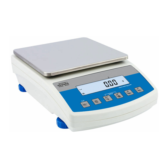
1. GENERAL INFORMATION WLC/A1, WLC/A2 precision scales enable fast and accurate mass measurements under laboratory and industrial conditions. The devices are equipped with an internal battery which allows their operation in places where there is no access to the mains. The WLC series features a stainless steel weighing pan, and a backlit LCD guaranteeing clear weighing result presentation. -
Page 6: Operation Under Conditions Difficult Due To Electrostatics
3. WARRANTY CONDITIONS A. RADWAG feels obliged to repair or exchange all elements that appear to be faulty by production or by construction. B. Defining defects of unclear origin and means of their elimination can only be realized with assistance of manufacturer and user representatives. -
Page 7: Design
4. DESIGN 4.1. Dimensions Figure 1a. WLC/A1 precision scale Figure 1b. WLC/A2 precision scale... -
Page 8: Connectors Arrangement
4.2. Connectors Arrangement Figure 2. Connectors view 1- power supply socket 12 VDC 2- RS232 (1) connector 3- RS232 (2) connector 4- USB A "host" 5- USB B "device" 4.3. Pins Overview Pin2 – RxD Pin3 – TxD RS232 (1) connector Pin4 –... -
Page 9: Unpacking And Installation
5. UNPACKING AND INSTALLATION • Unpack the device and place it on a flat and even surface. Keep it far away from any sources of heat. • Install the weighing pan, follow the below figures: WLC/A1 precision scale WLC/A2 precision scale 5.1. -
Page 10: Start-Up And Operation
3. Remove the hole plug. 4. Mount the hook and put the scale bottom side down. 6. START-UP AND OPERATION 6.1. Levelling To level the weighing instrument turn its feet. Keep turning the feet until the air bubble takes central position: 6.2. -
Page 11: Warm-Up Time
Nominal voltage of the power supply (specified on the power supply data plate) has to be compatible with the mains nominal voltage. Procedure: • Connect the power supply to the mains. Plug it to the power supply socket (back side of the scale housing). •... -
Page 12: Battery Charge Status Check
6.5. Battery Charge Status Check • Press keys combination. • Battery charge state, given in %, is displayed for 2 s. • Next, home screen is displayed automatically. 7. MAINTENANCE ACTIVITIES In order to ensure safety in the course of cleaning, it is necessary to disconnect the device from the mains. -
Page 13: Cleaning Stainless Steel Components
At the end of the cleaning process rinse the pane using distilled water. Use soft brush with wooden or plastic handle exclusively in order to avoid risk of scratches. Do not use wire brush. Rinsing is a necessary cleaning process stage allowing to remove remaining soap, detergents and other cleansers from the panes prior their reinstallation. -
Page 14: Operation Panel
8. OPERATION PANEL Operation panel of WLC/A2 precision scale Operation panel of WLC/A1/C/2, WLC/A2/C/2 precision scales 9. KEYS Press to switch the weighing device on/off – hold the key for about 1 second. Function key, press to change the working mode. -
Page 15: Program Structure
Press to tare the scale. Press to perform internal adjustment manually (WLC/A1/C/2, WLC/A2/C/2 scales). Upon pressing keys combination, functions of given keys change. Detailed information concerning use keys combination is to be found further down this manual. 10. PROGRAM STRUCTURE Program menu is divided into function groups. -
Page 16: Operating The Menu
10.2. Operating the Menu In order to navigate the program menu use the operation panel. Press to enter the main menu. Press to: • enter tare manually. • enter tare from tare database, • change value by 1 digit up, •... -
Page 17: Good Weighing Practice
11.1. Good Weighing Practice To assure long-term operation and correct mass measurements, follow the rules presented below: Load weighing steadily avoiding mechanical shocks. Place weighed loads centrally on the weighing pan (eccentricity errors are specified by EN 45501 standard, point 3.6.2.). -
Page 18: Taring
11.3. Taring To determine net weight value, load the weighing pan with a packaging, wait for a stable indication and press key. Zero indication and the following pictograms are displayed: Net and . The weighing device has been tared. Upon loading, net mass is displayed. Taring can be carried out repeatedly within the whole weighing range. -
Page 19: Units
To return to weighing with accuracy of the I weighing range: • Take the load off the weighing pan. • As the indication returns to zero and when symbols displayed, press button. • II weighing range pictogram/marker gets blank, the scale returns to weighings with the accuracy of the I weighing range. -
Page 20: Temporary Unit
11.6.2. Temporary Unit Temporary unit runs from the moment it is set to the scale shut-down and restart. Procedure: • Enter <P9.Unit / 9.2.Unin> submenu. • Press key, available units are displayed successively one by one. Options in case when the main unit is [kg]: •... -
Page 21: External Adjustment
Adjustment types: • external adjustment performed using an external weight of declared mass, i.e. mass that cannot be modified, • user adjustment performed using an external weight of mass of any value comprised within the weighing range, however not lower than 30% of the maximum capacity value. -
Page 22: User Adjustment
12.2. User Adjustment option available for non-verified scales exclusively External adjustment must be carried out using an external adjustment weight , and of mass value ≥ 30% of the maximum capacity value. of class F Procedure: • Enter <P1.CAL / 1.2.CA-u> submenu, edit box for declaring weight mass is displayed (the mass value must be ≥... -
Page 23: Automatic Internal Adjustment
12.4. Automatic Internal Adjustment Automatic internal adjustment is triggered: • after connection of the scale to the mains, • when temperature variation occurrs, • after passage of specified time interval. In case of an automatic internal adjustment it is necessary to declare condition that is to trigger the automatic adjustment. -
Page 24: Automatic Internal Adjustment Time
Adjustment upon passage of specified time interval • The scale is equipped with RTC, due to this time of each completed process is registered. • Adjustment process is triggered automatically after passage of particular time interval, set in <1.6.CAC> parameter. •... -
Page 25: Adjustment Report
12.7. Adjustment Report Adjustment report, and adjustment test report are both automatically printed (using scale-connected printer) at the end of each adjustment process. To declare report content go to <P6.1.CrEP> submenu. For detailed information concerning report content read later sections of this manual. 13. -
Page 26: Ambient Conditions
13.3. Ambient Conditions Parameter relating to ambient and environmental conditions of the workstation. Enter this parameter and set 'nStAb' value if the ambient conditions are unfavourable (air drafts, vibrations). Procedure: • Enter <P2.rEAd / 2.3.Enut> submenu. • Press key, parameter values are displayed successively one by one: nStAb –... -
Page 27: Tare: Enter Mode
Regular tare mode. Select this parameter to make the scale overwrite the set (selected) tare value with the most recently entered one. Select this parameter to make the scale store the latest tare value tArF in memory. The latest tare value is displayed after scale restart. Automatic tare mode. -
Page 28: Selecting Tare Value From The Weighing Device Memory
• Select respective entry and press key, tare value edit box is displayed. • Enter tare value, to do it press keys: Press to select digit that is to be edited. Press to set digit value, 0 - 9 . •... -
Page 29: Communication
Select to make the last digit on only when the weighing indication is stable. uuSt • Press key to confirm, next go to the home screen. 14. COMMUNICATION Communication between the scale and the peripheral devices is established via the following ports: RS232 (1), RS232 (2), USB type A, USB type B. To set the ports go to <... -
Page 30: Usb B Port
COM port in a computer. To carry out this procedure, you need a respective driver installer which either downloaded from website or taken from a CD with manuals: RADWAG USB www.radwag.pl DRIVER x.x.x.exe. Procedure: 1. Run the driver installer and follow the commands. Select language version and press button „OK”... - Page 31 In order to start installation process press „Next” button. Connect scale a computer, use 1.8-meter long cable maximum (in case of already connected scale, necessary to disconnect it and reconnect using USB cable). Respective message box is displayed, press OK button for confirmation. Press „Finish”...
-
Page 32: Peripheral Devices
„COM ports Screen” automatically displays number of installed COM port. In this very case it is COM8. 2. Enter < P5.ducE / 5.1.PC / 5.1.1.Prt> submenu and set <USbb> value. 3. Run program for measurements readout. 4. Set communication parameters – select COM port that was installed in the course of drivers installation (in this very case it is COM8). -
Page 33: Printout Interval For Continuous Transmission
• Press key to confirm, next go to the home screen. 15.1.3. Printout Interval for Continuous Transmission Parameter enabling you to set frequency of printout for continuous transmission. Printout interval is set in seconds with 0.1 [s] accuracy within 0.1 [s] - 3600 [s] range. -
Page 34: Additional Display Port
15.3.1. Additional Display Port • Enter <5.3.AdSP / 5.3.1.Prt> submenu. • Press key, parameter values are displayed successively one by one: nonE – none; rS1 – RS232 (1); rS2 – RS232 (2). • Press key to confirm, next go to the home screen. 16. -
Page 35: Glp Printout
Report example: 16.2. GLP Printout <P6.2.GLP> is a group of parameters allowing you to declare variables that are to be printed on a weighing printout. Each variable features accessibility attribute: YES – print, no – do not print. Variables list: Name Description 6.2.1. -
Page 36: Miscellaneous Parameters
17. MISCELLANEOUS PARAMETERS <P7.Othr> is a group of parameters enabling you to adapt the scale to individual needs. 17.1. Backlight Parameter allowing you to change display brightness, the brightness can be changed within 0% - 100% range. Procedure: • Enter <P7.Othr / 7.1.bLbt> submenu. •... -
Page 37: Date And Time
Shutdown function is inactive and the device cannot be turned off if any process is started or if you operate the menu. Procedure: • Enter <P7.Othr / 7.3.t1> submenu. • Press key, parameter values are displayed successively one by one: nonE –... -
Page 38: Scale Data
• Press key to confirm. The process of restoring default settings starts, this is signalled with display of 'dash', < - >. • Upon process completion <7.8.dFLu> submenu is displayed. Go to home screen. 18. SCALE DATA Scale data menu, <P8.InFo>, provides information on the weighing device and its program. -
Page 39: Working Modes Local Settings
19.2. Working Modes Local Settings Each working mode features specific (local) functions which enable adapting device operation to individual needs. The functions are to be found in local settings. To go to local settings of each working mode enter <P3.Func> submenu. -
Page 40: Automatic Printout Time Interval
• Press key, parameter values are displayed successively one by one: Manual printout of stable weighing result. Upon pressing key at the moment when the result is unstable (no pictogram displayed), the StAb program first waits for the stability condition to be met, only then printout is carried out. -
Page 41: Working Mode - Weighing
20. WORKING MODE – WEIGHING <UUGG> is a standard working mode enabling you to carry out the weighing operation along with record of the result to the database. 20.1. Local Settings To go to local settings enter <3.1.UUGG> submenu. Working mode accessibility For detailed description read section 19.2.1. -
Page 42: Setting Sample Mass By Entering Mass Of A Single Part
Select to set sample mass by determining mass of a single part. Select to set sample mass by entering mass of a single part. • Enter respective value and press key to confirm, then continue weighing. 21.2. Setting Sample Mass by Entering Mass of a Single Part •... -
Page 43: Working Mode - +/- Control
• Load the weighing pan with declared amount of parts. When the indication is stable ( pictogram is displayed), press key to confirm the mass. • Single part mass is calculated automatically, next quantity of parts (pcs) is displayed. Total weight value of all parts loaded onto the weighing pan cannot be greater than the max capacity value. -
Page 44: Working Mode - Percent Weighing
Load mass lower than low weighing threshold. Load mass within weighing thresholds. Load mass greater than high weighing threshold. If the entered low threshold value (Min) is greater than high threshold value (Max), <Err Lo> error is displayed. If the entered high threshold value (Max) is greater than the maximum capacity value, <Err Hi>... -
Page 45: Reference Sample Mass Determined By Weighing
• Set respective value and press key to confirm, next go to the home screen. 23.2. Reference Sample Mass Determined by Weighing • Enter <3.4.dEu / 3.4.2.UUt> submenu, set < > value. • Enter <dEu> working mode (Percent weighing), first, text <LoAd> is displayed for 1 second, then the weighing window. -
Page 46: Peak Hold Operation
24.2. Peak Hold Operation • Enter <3.5.toP / 3.5.2.Lo> submenu, set <Lo> parameter value (Lo threshold) after exceeding of which maximum force is to be registered. • Enter <toP> working mode (Peak Hold). From now on the scale registers and holds every single weighing which is above the Lo threshold, and which is higher than the result of the previous peak hold. -
Page 47: Working Mode - Animal Weighing
• Unload the weighing pan, ZERO is displayed, „▲” marker starts blinking again. • Load the weighing pan with the ingredient no.2, wait for a stable weighing result and press key. • Total mass value of ingredient no. 1 and 2 is displayed, now the „▲” pictogram is displayed continuously. -
Page 48: Local Settings
26.1. Local Settings To go to local settings enter <3.7.AnLS> submenu. Working mode For detailed description read section 19.2.1. 3.7.1.Acc accessibility Enter this parameter to declare duration of the process in seconds (5s, 10s, 20s, 30s, 40s, 50s, Averaging time 60s) - on the basis of indications recorded within 3.7.2.Aut the set time interval the scale calculates the... -
Page 49: Weighing Records Export
These files can be read using ALIBI Reader, PC software designed by RADWAG. You can download the software from RADWAG website: www.radwag.pl. -
Page 50: Inputs / Outputs
28.2. Inputs Setup • Enter <IO / In> submenu and edit given input. • Press key, available values are displayed successively one by one: Input inactive. Change unit. Zero. Tare. Print. Internal adjustment (function enabled in WLC/A1/C/2, WLC/A2/C/2 scales exclusively). -
Page 51: Outputs Setup
• Press key to confirm, next go to the home screen. By default all inputs' functions are set to <no> value. 28.3. Outputs Setup • Enter <IO / Out> submenu and edit given output. • Press key, available values are displayed successively one by one: Output inactive. -
Page 52: Diagrams Of Connection Cables
29. DIAGRAMS OF CONNECTION CABLES scale – computer cable scale - printer cable (EPSON) I/O cable... -
Page 53: Troubleshooting
30. TROUBLESHOOTING Problem Cause Solution Connect the scale to the mains, Battery discharged. charge the battery (batteries). The scale does not switch batteries (batteries Check if batteries are installed installed or installed incorrectly). correctly (polarization). <7.3.t1> parameter set to value The scale switches off Go to 'Othr' menu, set <7.3.t1>...
Need help?
Do you have a question about the WLC/A1/C/2 and is the answer not in the manual?
Questions and answers