Centurion D2 Turbo Installation Manual
Domestic sliding gate operator for 250kg gates
Hide thumbs
Also See for D2 Turbo:
- Quick installation manual (44 pages) ,
- User manual (42 pages) ,
- Pocket installation manual (13 pages)

Related Manuals for Centurion D2 Turbo


Summary of Contents for Centurion D2 Turbo
- Page 1 D2 Turbo and D2 Turbo Low-Voltage Installation Manual DOMESTIC SLIDING GATE OPERATOR FOR 250KG GATES...
-
Page 2: Company Profile
50 countries worldwide Centurion Systems (Pty) Ltd reserves the right to make changes to the products described in this manual without notice and without obligation of Centurion Systems (Pty) Ltd to notify any persons of any such revisions or changes. -
Page 3: Table Of Contents
Wiring Diagrams for External Radio Receiver page 41 Wiring Diagrams for Other Inputs page 42 Wiring Diagram for Pillar Light to the D2 Turbo Controller page 43 Wiring Diagram for Pillar Light to the D2 Turbo Low-Voltage page 44 Controller... - Page 4 Description of Terminal Functions page 77 Diagnostics page 79 Troubleshooting page 80 Manual Operation page 84 Additional Features page 85 Basic Maintenance page 86 Servicing the Operator page 87 Installation Handover page 88...
-
Page 5: Mechanical Setup
Mechanical Setup These abbreviated instructions are for the experienced installer who needs a checklist to get a standard installation up and running in the minimum of time. Detailed installation features and functions are referred to later in this manual. Required tools and equipment page 11 Site considerations page 12... -
Page 6: Electrical Setup
Electrical Setup Connect all wiring page 38-45 Commissioning and Handover Set the gate limits page 48 Set additional features page 87 Carry out professional page 90 handover to client page 2... -
Page 7: Important Safety Features
Never short-circuit the battery and do not try to recharge the batteries with power supply units other than that supplied with the product, or supplied by Centurion Systems Make sure that the earthing system is correctly constructed, and that... - Page 8 Centurion Systems does not accept any liability caused by improper use of the product, or for use other than that for which the automated system was intended ...
- Page 9 IMPORTANT Site Considerations for the D2 Turbo Low-Voltage Before you attempt to use your new gate motor for the first time, you should know: At no point must 220V be supplied to the system! This is a low-voltage model and connecting a voltage supply that...
-
Page 10: Declaration Of Conformity
Intersection Newmarket Road & Epsom Avenue North Riding Gauteng South Africa Declares that the product Product name: D2 Turbo/D2 Turbo Low-Voltage Sliding gate operator Conforms with the following specifications Safety: SANS 60335-1:2007 IEC 60335-1:2006 Emissions: CISPR 11 CLASS A - Radiated and conducted Interference field strength (emission tests) –... -
Page 11: General Description
For increased power capacity you can install a larger, 7Ah battery (your D2 Turbo was designed to cater for this), or you can even use a solar panel to power it (See the section on Solar Panels, for more details about solar charging). -
Page 12: Specifications
3. Specifications Physical dimensions Technical specifications D2 Turbo D2 Turbo Low-Voltage 90V - 240V AC ± 10V - 20V AC Input voltage 10%, 50Hz 10V - 28V DC Voltage output: 13.76V DC 10V AC 400mA input output 90V AC input... -
Page 13: Technical Specifications
Technical specifications D2 Turbo D2 Turbo Low-Voltage Current consumption (motor at rated load) Operator push force - starting 18kgf Operator push force - rated 9kgf Gate mass - maximum 250kg Gate length - maximum Gate speed (varies with load) 24m/min... -
Page 14: Product Identification
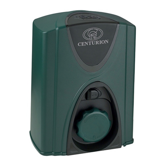
4. Product Identification Refer to the drawings below, for how to identify your D2 Turbo/D2 Turbo Low-Voltage motor and its parts. 1. Motor fuse 2. Motor enclosure unit 3. Camlock cover 4. Manual elease humbwheel 5. Foundation plate 6 . Function Dial 7 . -
Page 15: Required Tools And Equipment
5. Required Tools and Equipment Pull scale - 50kg Spanner - 17mm; 10mm Screwdriver - 3.5mm flat Allen key - 6mm; 4mm Crimping tool and pin lugs Side cutters Hacksaw Spirit level Measuring tape ... -
Page 16: Glossary
6. Glossary DOSS: Digital Origin Seeking System. An opto-electronic system that counts pulses in order to determine the position of the gate and the distance that it needs to travel to its respective endstops IRBO: Opening infrared Safety Beams. If the opening beams are interrupted while the ... -
Page 17: Preparation Of Site
7. Preparation of Site WARNING! Endstops are mandatory and must be fitted to prevent death or accidental injury should the gate overrun its limits Endstops Fit endstops capable of stopping the gate at rated speed. Refer to specifications at the beginning of this manual for the operating speed Make H>h to ensure gate will not jump over endstop ... -
Page 18: General Considerations For The Installation
General considerations for the installation Always recommend the fitment of additional safety equipment such as Safety Edges and Safety Beams, for additional protection against entrapment or other mechanical risks Check that no pipes or electrical cables are in the way of the intended installation ... - Page 19 Guide-rollers and anti-lift brackets Guide-rollers must ensure that the gate is held vertically For improved safety, fit additional support post to prevent gate from falling over if guide-rollers fail To prevent unauthorised access fit anti-lift brackets as shown ...
- Page 20 Starting and running forces Test the starting force of the gate as per the diagram. Use a pull scale to determine the maximum amount of pull force required to get the gate moving Determine the running force of the gate by continuing to pull on the scale with just sufficient force to keep it running and read off the maximum value in kgf shown on the scale ...
-
Page 21: Cabling Requirements
8. Cabling Requirements Legend 1. D2 Turbo: 230V AC mains cable via double mains isolator switch (3 core LNE 1.5mm² SWA) OR D2 Turbo Low-Voltage: 10V-20V AC/10V-28V DC cable via transformer in dwelling Optional wiring (all cable is multi-stranded): 2. Intercom cable from motor to dwelling (n1 + 6 core 0.5mm ) 3. -
Page 22: Lubrication
9. Lubrication The gearbox of the D2 Turbo is filled with grease during the assembly process, and the gearset does not have to be lubricated ex-factory. page 18... -
Page 23: Operator Installation
10. Operator Installation Locate operator position To ensure operator does not protrude into the driveway, install the foundation plate at least flush with the driveway entrance Determine a suitable position and vertical height for the operator by considering Figures 7, 8 and 9 With careful selection of the rack configuration, and operator vertical height, mounting of the rack could in some cases be greatly simplified. - Page 24 Foundation plate 148 - 158mm Foundation 148 - 158mm plate Flat bar welded to Raised foundation foundation plate and rail * Includes 3mm clearance required between rack and pinion FIGURE 8A. Above pinion - Nylon Angle rack FIGURE 8B. Below pinion - Nylon Angle rack Foundation 146mm plate...
-
Page 25: Foundation Plate Installation
11 to 17, or bolted down onto an existing concrete plinth as shown in Figure 18 and 19. If the D2 Turbo is being used to replace a D3 gate operator, refer to Figures 21 to Option 1: Cast foundation plate into concrete 2A.Bend the anchor brackets outwards... - Page 26 2B. Using a pair of long-nosed pliers, bend the ends of the anchor brackets at a 90° angle. 3. Fit the mounting bolts to the foundation plate and secure in place with nuts and washer.
-
Page 27: Bolt Foundation Plate Onto An Existing Concrete Plinth
ENSURE THAT MOUNTING STUDS AND LOCKNUTS ARE FITTED BEFORE setting the foundation plate in concrete or bolting to an existing plate. 4. Do not finish pouring concrete before the cables have been Option 2: Bolt foundation plate onto an existing concrete plinth 5. -
Page 28: Route Cables
6. Fit the mounting studs to the foundation plate and secure in place with the stud locknuts. Do not bend out the anchor brackets. Route Cables and Secure Foundation Plate 1. Route cables as determined in Section 7, Cabling Requirements. 2. -
Page 29: Retrofitting To An Existing D3 Foundation Plate
Option 3: Retrofitting D2 Turbo to a n existing D3 foundation plate. 1. Grind off the existing mounting studs from the D3 foundation plate as shown in Figure 21. 2. Fit the three mounting studs to the D2 Turbo foundation plate and secure in place using the stud locknuts supplied with this kit. - Page 30 D3 plate in the optimum position. 4. Carefully tack-weld the head of each individual mounting stud onto the D3 foundation plate. 5. Remove the hold-down nuts and lift the D2 Turbo f oundation plate off of the mounting studs.
- Page 31 Route Cables and Secure Foundation Plate 1. Route cables as determined in Section 7, Cabling requirements. 2. Make sure that all cables and conduits protrude at least 400mm above the foundation plate once installed. Cable entry is allowed for in the far left- hand side corner of the gearbox.
- Page 32 2. Adjust the nuts to be 7mm clear from the base to allow for later adjustment. 3. Secure the gearbox in place, fitting a washer, spring washer and M10 hold- down nut onto each gearbox mounting. 4. Feed the cables through the dedicated cable entry indent while fitting the gearbox to the foundation plate.
- Page 33 (M10 nuts) FIGURE 33. Theft-resistant Nut and Discus padlock are available from Discus Centurion Systems for sites padlock requiring additional security. Theft- resistant FIGURE 34. 7. Seal the conduit with silicone to prevent ants from entering the operator.
-
Page 34: Mount The Rack
Mount the rack The rack must be securely mounted to the side of the gate, it must be parallel with Rack the gate rail and there must be parallel to rail a 2mm - 3mm gap between the teeth of the pinion and the rack Gate rail Gate rail along the entire travel of the... - Page 35 3. Start with the gate either fully open or fully closed. Level this end 4. Place the one end of the first section of of the rack, and fix rack on the pinion. Let it mesh fully. 5. Level the other end and fix that end to the side of the gate.
- Page 36 Steel rack 1. Fit the rack using the steel angle brackets provided. 2. Brackets must be spaced no more than 300mm apart. FIGURE 41. 3. When joining the different lengths of steel rack, a simple way of ensuring correct pitch spacing, is to clamp a small off-cut between the two pieces.
- Page 37 3. When fitting RAZ rack it is easier to start on the right and work towards the left. 4. RAZ rack simply clips together. Start on the right FIGURE 44. Fit additional fixing screws through the horizontal slots to secure the rack to the gate directly above the pinion when the gate is in the closed, pedestrian and open positions.
- Page 38 3. When joining two lengths together, simply butt each section firmly together to ensure the correct pitch. Butt firmly together FIGURE 47. Mount the origin marker Close the gate 1. Close the gate completely. page 34...
- Page 39 2. Mount the origin marker to the rack, Isometric view A making sure that there is a minimum of 500mm from the origin sensor. Refer to Figure 49, isometric view A or plan view It is possible to make the distance between the origin marker and the origin sensor much greater than Greater than 500mm...
- Page 40 9. With Nylon Angle rack it is necessary to Nylon angle rack use the bracket provided. Bolt using 10. It is preferable to use self-tapping fasteners provided fasteners to secure the bracket into the side of the nylon rack as shown. 11.
- Page 41 Apply warning decal Apply the supplied warning decals to both sides of the gate as indicated in the second drawing on the reverse side of the decal. page 37...
-
Page 42: Connect All Wiring
11. Electrical Setup 1. Always check that the circuit breaker in the electrical panel is in the OFF position, and that all high-voltage circuits (more than 42.4V) are completely isolated from the mains supply before doing any work. 2. Ensure that all low-voltage systems (less than 42.4V) are suitably protected from damage, by disconnecting all sources of power such as chargers and batteries before doing any work. -
Page 43: Wiring Diagram For Closing Safety Beams
12. Wiring Diagram for Closing Safety Beams Closing Safety Beam 12V/24V - 12V/24V + IRB Receiver 12V/24V + 12V/24V - IRB Tx FIGURE 58. page 39... -
Page 44: Wiring Diagram For Opening Safety Beams
13. Wiring Diagram for Opening Safety Beams Opening Safety Beam 12V/24V - 12V/24V + IRB Receiver 12V/24V + 12V/24V - IRB Tx FIGURE 59. page 40... -
Page 45: Wiring Diagrams For External Radio Receiver
14. Wiring Diagram for External Radio Receiver External radio receiver 12V+ Remote control circuitry Refer to diagram only if external receiver is being used and not the onboard receiver, disable onboard receiver - Menu 11 FIGURE 60. page 41... -
Page 46: Wiring Diagrams For Other Inputs
15. Wiring Diagram for Other Inputs Holiday Lockout keyswitch/keypad (normally-closed) Intercom pushbutton (normally-open) Pedestrian keyswitch/keypad (normally-open) Status FIGURE 61. page 42... -
Page 47: Wiring Diagram For Pillar Light To The D2 Turbo Controller
16. Wiring Diagram for Pillar Light to the D2 Turbo Controller 90V - 240V Mains in Waterproof isolator enclosure within two metres of motor Pillar Light/Courtesy Light Optional page 43... -
Page 48: Wiring Diagram For Pillar Light To The D2 Turbo Low-Voltage Controller
17. Wiring Diagram for Pillar Light to the D2 Turbo Low-Voltage Controller Step-down transformer capable of supplying 90V - 240V the controller with Mains in 10V - 20V AC or 10V - 28V DC Pillar Light/Courtesy Light Optional Must be low-voltage globe or separate PSU must be provided! FIGURE 63. -
Page 49: Mains Supply And Battery Connections
18. Mains Supply and Battery Connections Mains supply Battery leads FIGURE 64. FIGURE 65. page 45... -
Page 50: Earthing For Effective Lightning Protections
19. Earthing for Effective Lightning Protection Spade connector Optional 40kA surge arrestor 90V - 240V Mains in Earth spike (>1m copper rod hammered into the ground) FIGURE 66. page 46... -
Page 51: Commissioning The System
20. Commissioning the System Introduction The D2 Turbo and D2 Turbo Low-Voltage sliding gate operators’ advanced functions are controlled by intelligent microcontroller-based electronic controllers. These systems’ features and functions are enabled and disabled using the two user-friendly setting dials, with the top dial used for selecting the desired function, and the bottom dial used for selecting the specific setting to be enabled or disabled. - Page 52 4B. The gate will then run through its automated procedure to determine the gate's open and closed positions. If Setup is successful, that status LED will be green, which indicates that Setup has finished. FIGURE 70. 5. Return the Function Dial to the RUN position.
-
Page 53: Features And Functions
21. Features and Functions Function Dial Select/ Toggle pushbutton Settings Dial FIGURE 72. D2 TURBO CONTROLLER (ORANGE) Function Dial Select/ Toggle pushbutton Settings Dial FIGURE 73. D2 TURBO LOW-VOLTAGE CONTROLLER (DARK GREEN) page 49... -
Page 54: Gate Operation
D2 Turbo controller to operate the gate. FIGURE 74. 21.1.2. Modes of Operation To operate the gate to open fully, the D2 Turbo has three modes to choose from depending on the application. Only one mode can be selected at any given time. 21.1.2.1. Standard Mode Standard Mode is the most commonly used mode for domestic applications as it allows full control of the gate. - Page 55 We highly recommend that a pair of Safety Beams are installed across the gate entrance and connected to the Closing Safety Beam input on the D2 Turbo if you select Open Only Mode. This will prevent the gate from closing on people, pets or vehicles (page 50).
-
Page 56: Pedestrian Opening
Your gate will stay open until you use the remote control or intercom gate release to close the gate. The D2 Turbo will then revert to normal Autoclose operation. Gate stops to indicate that Autoclose Override has been engaged The Autoclose function cannot be overridden in Only Open Mode. - Page 57 It will also give the person enough time to move their hand away if they are reaching through the gate to operate a keyswitch or a keypad . If the Courtesy Light (page 58) is connected to the D2 Turbo control card, it will flash indicating that the gate will open approximately one metre.
- Page 58 Autoclose time has expired when the beam has been cleared. Please contact Centurion Systems for more information on suitable protection devices. 21.1.5.2. Opening Safety Beams These beams prevent your gate from opening if an object, person or pet is in the way.
-
Page 59: Holiday Lockout Mode
When Holiday Lockout is enabled, any of the access control devices that are connected to the D2 Turbo will be rendered inactive. Not even tampering with the keyswitch or keypad on the outside of the property will open the gate –... -
Page 60: Speed Profiles
21.1.8 . Speed Profiles The D2 Turbo can be set to run on either a High Speed Mode (default) which is approximately 24 metres per minute, or a Low Speed Mode which is approximately 16 metres per minute. High speeds offer a greater level of convenience and security, while slower speeds ensure increased levels of safety at the gate. - Page 61 Gate opening With PIRAC Mode enabled, your gate will close as soon as you have driven through and passed the Safety Beams – giving intruders no time to follow behind you. Beam FIGURE 82. Gate opening If Autoclose is enabled and the gate has been opened but nothing moves through the Closing Safety Beam, the gate will stay fully open for the duration of the Autoclose timer...
- Page 62 Using the Pedestrian Opening feature will cause the Courtesy (Pillar) Lights to flash three times before the gate opens. The cabling that supplies the input voltage to the D2 Turbo must be suitably sized to carry the additional load of the Courtesy (Pillar) Lights.
-
Page 63: External Gate Status Indication Led
The gate system will also shut off until such time as the battery has recharged to an acceptable level. Consult your gate automation specialist or Centurion Systems if you discover that your Battery-low Protection signal continues to re-occur. -
Page 64: Customising The Features And Functions
22. Customising the Features and Functions ‘Simplicity is the ultimate sophistication’. ~ Leonardo Da Vinci The D2 Turbo and D2 Turbo Low-Voltage controllers make ordinarily complex settings as quick and easy as possible. Using the Function and Setting Dials, the Select/Toggle... - Page 65 This ensures that it will be ready for use. FIGURE 92. 22.1. Remote control administration The D2 Turbo controllers incorporate an onboard multichannel receiver compatible with code-hopping technology. The receiver will allow any combination of the different inputs - Trigger (Gate fully open), Pedestrian, Holiday Lockout, etc.
- Page 66 FIGURE 94. However, it’s important to note that the other devices cannot be activated with the new Shift button, only the D2 Turbo (and other operators that are equipped with an onboard receiver) is able to recognise the Shift button signals.
- Page 67 You can choose from the following settings: Tx TRG to assign a remote control button to be learned into the system and trigger the gate to fully open Tx PED to assign a remote control button to be learned into the system and partially open the gate for a pedestrian ...
- Page 68 22.3. Deleting specific remote controls To delete specific remote controls from the D2 Turbo's onboard receiver, please follow the steps below: Step 1: Rotate the Function Dial to the REMOTES position (B). Step 2: Rotate the Setting Dial to DELETE Tx along the ‘B’...
- Page 69 22.4. Deleting all remote controls To delete all the learned-in remote controls from the D2 Turbo onboard receiver, please follow the steps below: Step 1: Rotate the Function Dial to the REMOTES position (B). Step 2: Rotate the Setting Dial to DELETE ALL along the ‘B’...
- Page 70 22.5. Setting the Autoclose feature The Autoclose feature can be selected to be either Off or Activated, with a pre-selected time delay. 22.5.1. Activating the Autoclose feature To activate the Autoclose, with a pre-selected time delay, please follow the steps below: Step 1: Rotate the Function Dial to the AUTOCLOSE position (C).
- Page 71 Step 4: Return the Function Dial to the RUN position. FIGURE 109. Please note that if the operator is running in Open Only Mode – the Autoclose feature is activated with a 15 second delay as the default – this can be changed if necessary.
- Page 72 Autoclose feature cannot be deactivated. 22.6. Setting the Mode of Operation The D2 Turbo has three modes to choose from depending on the application. Only one mode can be selected at any given time. 22.6.1. Standard Mode To activate Standard Mode please follow...
- Page 73 Step 4: Return the Function Dial to the RUN position. Please note that PIRAC Mode can be active in addition to this mode if so desired. 22.6.2. Open Only Mode To activate Open Only Mode please follow these steps: Step 1: Rotate the Function Dial to the MODE position (D).
- Page 74 Step 4: Return the Function Dial to the RUN position. Please note that PIRAC Mode can be active in addition to this mode if so desired. FIGURE 118. 22.6.3. Reversing Mode To activate Reversing Mode, please follow the steps below: Step 1: Rotate the Function Dial to the MODE position (D).
- Page 75 Step 4: Return the Function Dial to the RUN position. Please note that PIRAC Mode can be active in addition to this mode if so desired. FIGURE 121. 22.7. Setting PIRAC Mode PIRAC (Beam Autoclose) Mode can be activated when using any of the three Operating Modes (Standard, Open Only, or Reversing).
- Page 76 Step 4: Return the Function Dial to the RUN position. FIGURE 124. 22.8. Setting the Pre-flashing Modes Pre-flashing Mode A and Pre-flashing Mode C can be activated in addition to any of the above Modes of Operation. To select a Pre-flashing Mode as either on or off, please follow the steps below: Step 1: Rotate the Function Dial to the MODE position (D).
- Page 77 22.9. Setting the Operating Profiles Three Operating Profiles, Positive Close Mode, Speed and Collision Sensitivity, can each be configured depending on your individual requirements. 22.9.1. Positive Close Mode To activate or deactivate Positive Close Mode, please follow the steps below: Step 1: Rotate the Function Dial to the PROFILE position (E).
- Page 78 22.9.2. Setting the Speed Profile to High or Low To select the desired speed profile, either High (approximately 24m/min) or Low (approximately 16m/min) please follow the steps below: Step 1: Rotate the Function Dial to the PROFILE position (E). Step 2: Rotate the Setting Dial to SPEED hi/lo along the ‘E’...
- Page 79 22.9.3. Setting the Anti-crushing Sensitivity Profile To select the desired sensitivity of the anti-crushing technology to either High or Low, please follow the steps below: Step 1: Rotate the Function Dial to the PROFILE position (E). Step 2: Rotate the Setting Dial to SENS hi/lo along the ‘E’...
-
Page 80: Factory Defaults Schedule
22.11. Reverting to Factory Defaults It is possible to clear and default the system completely, resetting all programmed settings to default values and clearing all learned remotes as well as gate limits. To perform a complete reset: Remove power from the unit by disconnecting both the mains supply and one battery terminal ... -
Page 81: Description Of Terminal Functions
23. Description of Terminal Functions Motor Motor output – connects to the Blue or Black motor wire. Motor Motor output – connects to the Orange or Red motor wire. Batt + Positive battery connection. Battery terminal normally indicated as + or red (right-hand battery) Batt - Negative battery connection. - Page 82 Safe OPN OPENING edge safety input. (A normally-closed potential-free input). As long as a connection between this input and COM is maintained the controller will behave normally. When this connection is broken it will prevent the gate from opening if it is stationary, and will stop and reverse the gate if it is opening.
-
Page 83: Diagnostics
24. Diagnostics Diagnostic LEDs The D2 Turbo controller has a series of diagnostic LEDs which indicate the state of the inputs. Normally-open inputs are indicated by a RED LED, and normally-closed inputs by a GREEN LED. An illuminated RED LED indicates that the signal is present (e.g. intercom button pressed), while an illuminated GREEN LED indicates that the signal is absent (e.g. -
Page 84: Troubleshooting
25. Troubleshooting Problem Possible faults Fuse is blown – Check 30A ATO fuse, and replace if necessary LCK (Holiday lockout) input activated. Green LCK light should be ON IRBC/IRBO (IR beams) inputs activated IRBC - gate will not close once open; IRBO - ... - Page 85 Problem Possible faults Carefully check the condition of the harness. Look out for any bad crimp joints between the wires and the connectors at both ends of the harness Check that the magnetic switch is mechanically switching. In manual mode, slide the gate backwards and forwards so that the magnet passes the switch each time.
-
Page 86: Low-Battery Voltage Condition
Check that the mains power is turned ON (measure 90V - 240V AC on the mains connector for the D2 Turbo, or 10V - 20V AC/10V - 28V DC for the D2 Turbo Low- Voltage) Check the condition of the battery leads, terminals and connectors. Look for and ... -
Page 87: False Collision Detection
Procedure B - False collision detection Status light flashes four times to indicate that number of collisions have exceeded the Collision Counter feature value. With the operator in Manual Mode, check the following and correct if necessary: Check for badly running gate, or something physically obstructing the gate. ... -
Page 88: Manual Operation
26. Manual Operation 26.1. Disengage the gearbox/drive To manually override the operator you will need to: 1. Open the camlock cover, insert the camlock key and rotate it 90° clockwise (the cover can also be removed at this stage if so desired). This will allow for the rotation of the Manual Release thumbwheel. -
Page 89: Additional Features
FIGURE 142. details on what solar panel to select in your area. The mains fail buzzer can be silenced on the D2 Turbo Low-Voltage by inserting a wire link between Aux 12V and power input terminal. FIGURE 143. page 85... -
Page 90: Basic Maintenance
28. Basic Maintenance CENTURION operators are designed to be maintenance-free. However, there are some basic checks that should be carried out regularly (every six months). These checks will increase the long-term reliability of the system and prevent erratic operation of your gate. -
Page 91: Servicing The Operator
Refer all servicing to qualified service personnel. Consult your local dealer for assistance. Your D2 Turbo sliding gate operator requires no special care other than that described in the Maintenance section. If you are having a problem with your D2 Turbo, please contact your installer or local dealer. -
Page 92: Installation Handover
Centurion Systems (Pty) Ltd does not accept any liability caused by improper use of the product, or for use other than that for which the automated system was designed. - Page 93 Centurion Systems (Pty) Ltd does not accept any liability caused by improper use of the product, or for use other than that for which the automated system was designed.
- Page 96 YouTube.com/CenturionSystems Subscribe to the newsletter: www.CentSys.com/Subscribe Sharecall 0860-CENTURION (0860 236 887) Head Office: +27 11 699 2400 Sharecall Technical Support 0861 003 123 or +27 11 699 2481 from 07h00 to 18h00 (GMT+2) (Sharecall numbers applicable when dialed from within South Africa only) 0.07.A.0229_28032014...
Need help?
Do you have a question about the D2 Turbo and is the answer not in the manual?
Questions and answers