Table of Contents
Advertisement
Quick Links
Download this manual
See also:
User Manual
Advertisement
Table of Contents
Troubleshooting

Related Manuals for Printronix T4204


Summary of Contents for Printronix T4204
- Page 1 ® Maintenance Manual T4204 Label Printer...
- Page 3 T4204 Label Printer Maintenance Manual ® 750513-001B...
-
Page 4: Communication Notices
Properly shielded and grounded cables and connectors must be used in order to meet FCC emission limits. Printronix is not responsible for any radio or television interference caused by using other than recommended cables and connectors or by any unauthorized changes or modifications to this equipment. - Page 5 Communication Notices EN 55022 Klasse A Geräte bedürfen folgender Hinweise: Nach dem EMVG: “Geräte dürfen an Orten, für die sie nicht asreichend entstört sind, nur mit besonderer Genehmigung des Bundesminesters für Post und Telekommunikation oder des Bundesamtes für Post und Telekommunikation betrieben werden.
- Page 6 Thermal Printhead Printronix warrants the printhead for a period of ninety (90) days, or 1,000,000 linear inches (Thermal Transfer/Direct Thermal) of use, whichever comes first. The warranty does not cover printheads that have been misused, damaged due to improper cleaning, or damaged due to use of improper ribbons or media.
- Page 7 Trademark Acknowledgements On-site Maintenance Service Printronix offers on-site support services in the United States. Please contact the Printronix Maintenance Contracts Group at (714) 368-2798, for service agreement information. Trademark Acknowledgements ANSI is a registered trademark of American National Standards Institute, Inc.
- Page 8 Trademark Acknowledgements...
-
Page 9: Table Of Contents
Maintenance Overview ........13 About This Manual................13 Replacing Parts ................13 Ordering Parts ................13 Printronix ThermaLine Help Desk ..........14 Notes And Notices ................ 14 Related Manuals And Packaging Components......15 About The Printer................. 15 Thermal Printer Technology ............15 Thermal Printer Media.............. - Page 10 Table of Contents Communications Failures ..............43 Ribbon Wrinkle Adjustment ..............45 4 Replacing Printer Components ......49 Removal Procedures ................49 Required Tools ................49 Torque Requirements ..............50 List Of Removal And Replacement Procedures......50 Top Cover Assembly ..............52 Printhead..................
- Page 11 Table of Contents B Printer Supplies..........121 Printronix Supplies Work Best ............121 Supplies ..................... 121 Genuine Printronix Thermal Transfer Ribbons......121 Genuine Printronix Media............122 C ASCII Codes ............ 125 D Downloading Software ........129 Flash Memory ..................129...
- Page 12 Table of Contents...
-
Page 13: Maintenance Overview
Maintenance Overview About This Manual This field service maintenance manual is designed so that you can locate maintenance information quickly in the Table of Contents or Index. Replacing Parts 1. Go to Chapter 4, page 49. 2. Find the removal procedure for the part. 3. -
Page 14: Printronix Thermaline Help Desk
Specifying the proper media and ribbon • Post sales service support questions Call the Printronix ThermaLine Help Desk at (949) 221-2488 or visit the Printronix Web Page at http://www.printronix.com. Notes And Notices For your safety and to protect valuable equipment, it is very important that you... -
Page 15: Related Manuals And Packaging Components
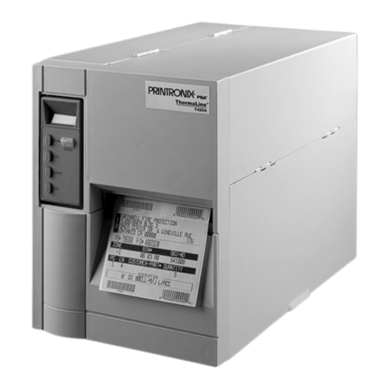
Printer Shipaway Kit (Packing) 136696-033 About The Printer The T4204 is a low cost, direct thermal and thermal transfer printer designed to print labels and tags with or without bar codes from any MS-DOS®, Windows®, or ASCII-based computer. The printer includes the following features: •... -
Page 16: Thermal Printer Media
If uneven print density occurs, it is usually caused by the stored heat from previous dots. The T4204 printer uses Dynamic Print Control technology to ensure even print density. Dynamic Print Control is printer software that tracks and adjusts printhead temperatures. -
Page 17: Ribbons
Emulations And Languages The printer comes with the Printronix LP+ and IGP®/VGL emulations and the Printronix IGP/PGL® programming language. The Printronix LP+ emulation provides complete compatibility with Printronix P-Series and P5000 series printers. -
Page 18: Controls And Indicators
Chapter Controls And Indicators Controls And Indicators Except for the power switch, printer controls and indicators are located on the front panel of the printer, on either the Primary Control Panel or the Secondary Control Panel. (See Figure 1.) Legend: Primary Control Panel Secondary Control Panel PAUSE Key... -
Page 19: The Power Switch And Indicator
The POWER Switch And Indicator The POWER Switch And Indicator The power switch is on the rear panel of the printer, in the bottom left corner just above the connector for the AC power cord. (See Figure 2.) A back-lit LCD or any message on the LCD panel indicates that printer power is ON. -
Page 20: Operating Modes
Chapter Controls And Indicators Operating Modes Online - In online mode, the printer can receive and print data sent from the host. Pressing the PAUSE key toggles the printer between the online and offline mode. The ONLINE status indicator is lit in online mode. Offline - In offline mode, you may perform operator functions, such as loading media, or navigating through the printer configuration menu to make changes or verify option settings. - Page 21 Secondary Control Panel Keys PREV ( ) - Navigates between options on the current level of the printer menu (offline mode only). < NEXT ( ) - Navigates between options on the current level of the printer menu (offline mode only). >...
- Page 22 Chapter Controls And Indicators...
-
Page 23: Preventive Maintenance
Preventive Maintenance Cleaning The Printer The T4204 printer is a simple, reliable device, designed to require very little maintenance. Aside from normal replenishment of print media and ribbons, the only preventive maintenance required is periodic cleaning. Because operating conditions vary widely, the user must determine how often to clean the printer. -
Page 24: Clean The Thermal Printhead
Chapter Cleaning The Printer Clean The Thermal Printhead A clean printhead ensures good print quality. The operator must routinely clean the printhead when installing a new roll of ribbon (Thermal Transfer mode) or when installing a new roll of media (Direct Thermal mode). 1. -
Page 25: Printer Inspection
Inspect Drive Belts Printer Inspection After cleaning the printer, thoroughly inspect all wear items and mechanical components, as outlined below. Inspect Drive Belts Inspect all belts for cracks, cuts, fraying, and wear. Replace any damaged or worn belt. Refer to Figure 4. Inspect Cables And Cords Inspect all cables and electrical cords for cracks, cuts, fraying, or exposed conductors. - Page 26 Chapter Printer Inspection Legend: Controller PCBA (Printed Circuit Board Assembly) Center Panel Passage, Sensor Cables Printhead Data/Power Cable (to Controller Connector J6) Center Panel Passage, Printhead Cables Ribbon Drive Belt Platen Drive Belt Center Panel Passage, Motor Cable Power Supply Power Cable Connector (to Controller Connector J5) 10) Control Panel Cable (to Controller Connector J13) 11) Power Plug and AC Power Switch Module...
-
Page 27: Diagnostics And Troubleshooting
Diagnostics and Troubleshooting Introduction This chapter lists fault messages and general fault symptoms, and provides procedures for troubleshooting printer malfunctions. You must operate the printer to check its performance, and sometimes you may have to reconfigure it. Always have the User’s Manual handy when you troubleshoot because this manual does not cover printer operation or configuration, nor does it repeat the troubleshooting information covered in the User’s Manual . -
Page 28: How To Troubleshoot
Chapter How To Troubleshoot How To Troubleshoot Standard fault isolation techniques are summarized below: 1. Ask the operator to describe the problem. 2. Verify the fault by running a diagnostic printer test or by replicating conditions reported by the user. 3. -
Page 29: Troubleshooting Display Messages
How To Clear LCD Messages You can run the Test Print program from the printer through the TEST key on the Primary Control Panel or through the Secondary Control Panel Diagnostics menu. NOTE: Before printing test labels, make sure the printer is set for the type of media installed. - Page 30 Chapter Troubleshooting Display Messages Table 1. Message List Message Explanation Solution The host computer sent data 1. Make a configuration BUFFER OVERFLOW through a serial interface after printout. Verify that the the printer buffer was full. printer matches the host serial interface configuration settings for Data Protocol, Baud Rate, Data Bits, Stop...
- Page 31 How To Clear LCD Messages Table 1. Message List Message Explanation Solution CUTTER FAULT The Cut option was selected in Check that the cutter option the MEDIA HANDLING menu is installed and connected. Check Cutter and printer has detected a fault. Install the cutter option or change to the correct Media Handling selection in the...
- Page 32 Chapter Troubleshooting Display Messages Table 1. Message List Message Explanation Solution FILE EXISTS The printer operator tried to Enter the File System sub-menu Enable Overwrite save a file using the name of an of the MAINT/MISC menu and existing stored file. enable the overwrite files feature to overwrite an existing file.
- Page 33 How To Clear LCD Messages Table 1. Message List Message Explanation Solution LABEL PRESENT NOTE: When this message 1. Remove the label from the Remove Label appears do not press front of the printer. any key until after the 2. The incorrect Media label is removed.
- Page 34 Chapter Troubleshooting Display Messages Table 1. Message List Message Explanation Solution OPTION NOT The Cut option was selected in 1. Check that the cutter option INSTALLED the MEDIA HANDLING menu is installed and connected. and printer has detected a fault. Install the cutter option or change to the correct Media Handling selection in the...
- Page 35 How To Clear LCD Messages Table 1. Message List Message Explanation Solution This is a printer protection The time before the printer P/H Control Mode feature. P/H stands for reaches P/H Control Mode can printhead. When the printer be extended by doing the senses that the printhead following: temperature is between131°...
- Page 36 Chapter Troubleshooting Display Messages Table 1. Message List Message Explanation Solution PRINT HEAD HOT The printhead has overheated. 1. Allow printhead to cool See Manual down for 5 minutes, then press CLEAR. Resume printing. 2. A dirty printhead can inhibit heat dissipation.
- Page 37 How To Clear LCD Messages Table 1. Message List Message Explanation Solution SOFTWARE ERROR* Application software tried to 1. Cycle power. If the message Recycle Power perform an illegal printer appears, power off the function or damaged logic printer. circuits were detected on the 2.
-
Page 38: Troubleshooting Other Symptoms
Chapter Troubleshooting Other Symptoms Troubleshooting Other Symptoms Use standard fault isolation techniques to troubleshoot malfunctions not indicated by display messages. These techniques are summarized below: 1. Ask the operator to describe the problem. 2. Verify the fault by running a diagnostic printer test or by replicating conditions reported by the user. - Page 39 How To Clear LCD Messages Table 2. General Symptom List Symptom Solution Communications Failures page 43 Control Panel LCD Message Display 1. Verify that the labels are the correct type (direct thermal). illuminated, the printer Load the correct type of labels. appears to be working, but 2.
- Page 40 3. Make sure the correct ribbon and media combination are being used. Use the correct ribbon type. Genuine Printronix Supplies are highly recommended to ensure the best possible print quality. 4. Check the ribbon for creases or folds across its surface.
- Page 41 How To Clear LCD Messages Table 2. General Symptom List Symptom Solution Printer Operation Advances several labels when 1. Check that labels are loaded correctly; labels can FEED button is pressed mistakenly be routed above the label guide and sensor assembly instead of through it.
- Page 42 Chapter Troubleshooting Other Symptoms Table 2. General Symptom List Symptom Solution Ribbon Printer advances media, but 1. Check that the ribbon is installed correctly. Install ribbon. ribbon does not advance 2. A bad ribbon/media combination can cause insufficient friction between media and ribbon. Verify that the correct ribbon is being used.
-
Page 43: Communications Failures
How To Clear LCD Messages Communications Failures Many host-printer communications problems are complex. With the exception of a defective interface cable, most communications problems are not a result of a hardware failure. Communications problems usually result from incompatible configuration of the host computer system, network (LAN, print server, controller, multiplexer, etc.), or the printer. - Page 44 Chapter Communications Failures Table 3: Common Communications Problems Problem Interface Common Causes Fails to print from host parallel - Interface cable defective -or- - Host/Network configuration Prints incorrect characters - Printer logic -or- - Terminating Resistors Prints extra characters -or- Drops characters serial - Host/Printer interface cable pinouts incompatible...
-
Page 45: Ribbon Wrinkle Adjustment
How To Clear LCD Messages The Printer Interface The printer will not function properly if an incorrectly wired interface cable or the wrong interface cable is installed. When the printer is first powered up, it resets itself to the following default communication parameters: PARAMETER DEFAULT VALUE Baud... - Page 46 Chapter Ribbon Wrinkle Adjustment T4ipb10 Legend: Machine Screws (3). (Loosen to adjust.) Ribbon Exit Path Area, Stress Lines Slanted to Left Side Plate Ribbon Exit Path Area, Stress Lines Slanted to Right Figure 5. Ribbon Wrinkle Adjustment, Ribbon Exit Path Area...
- Page 47 How To Clear LCD Messages 6. While feeding labels and ribbon through the printer, watch the area of the ribbon behind the printhead assembly for wrinkle stress lines. (See Figure 7. If there are any ribbon stress lines in the ribbon area behind the printhead, adjust the bar up or down in the vertical slot until the stress lines run vertically from the ribbon supply roll.
- Page 48 Chapter Ribbon Wrinkle Adjustment...
-
Page 49: Replacing Printer Components
Verletzungen oder Geräteschäden entstehen. Falls die Wartungsarbeit Stromzufuhr erfordert, wird im Wartungsablauf darauf hingewiesen. Required Tools You do not need many tools and materials to service the T4204 printer: • Flat Tip Screwdriver • Phillips Screwdriver, #1 and #2 •... -
Page 50: Torque Requirements
Chapter Removal Procedures • 0.005 inch shim • Clutch Torque Bit (P/N 136696-034) • Static Wrist Strap Torque Requirements Unless specified otherwise, use the following torque values when tightening fasteners: Bolt/Screw Size Torque (English) Torque (Metric) 5.7 ± 1 inch-pound 64.4 ±... - Page 51 List Of Removal And Replacement Procedures Printhead Carriage Assembly ............page 88 Label and Ribbon Tube Assemblies ..........page 90 Shaft Support Housings ..............page 92 Media Support Assembly .............. page 93 Checking and Adjusting Cable Clearances ........page 94 Sensor and Printhead Data/Power Cable Clamps ......
-
Page 52: Top Cover Assembly
Chapter Removal Procedures Top Cover Assembly To remove the top cover, follow the steps below and refer to Figure 7. 1. Lift the top cover (1), place it in the open position, and loosen the two Phillips head screws located on the top center panel of the printer (2). 2. - Page 53 Top Cover Assembly (Two bottom screws at lower left side not shown) Legend: Top Cover (shown in open position) Screws (Two at top; two at lower left side) Figure 7. Top Cover Removal...
-
Page 54: Printhead
Chapter Removal Procedures Printhead To remove the printhead, follow the steps below and refer to Figure 8. 1. Remove the top cover assembly (page 52). 2. Push the printhead release latch (1) to the rear to open the printhead carriage assembly (2). 3. - Page 55 Printhead Legend: Printhead Release Latch Printhead Carriage Assembly Mounting Screw Access Hole Printhead Data/Power Cable Connector Printhead Printhead Alignment Holes Figure 8. Printhead Replacement...
-
Page 56: Power Supply
Chapter Removal Procedures Power Supply To remove the power supply, follow the steps below and refer to Figure 9. IMPORTANT If you are replacing a 200W power supply (no longer available), install the newer 300W power supply and cable assembly 750882-001. (This cable assembly must be used with a 300W power supply and is not compatible with earlier 200W power supplies.) A 200W power supply can be identified by the fuse value “5A, 250V”... - Page 57 Power Supply Legend: Cable Tie Screw Power Supply Assembly Cable Tie Anchor Figure 9. Power Supply...
-
Page 58: Converting Power Supply Voltage
Chapter Removal Procedures Converting Power Supply Voltage You can change the input voltage of the power supply from 115 volts AC to 230 volts AC, or vice versa. To convert power supply voltage, follow the steps below and refer to Figure 10. IMPORTANT Earlier printers may have a 200W power supply, which permits the choice of 110V or 230V. - Page 59 Converting Power Supply Voltage Legend: Power Supply Assembly 230V Jumper Post Input Power Selector Jumper On 115V Post Figure 10. Converting Power Supply Voltage...
-
Page 60: Power Supply Fuse
Chapter Removal Procedures Power Supply Fuse To replace the T6.3A, 250V power supply fuse, follow the steps below and refer to Figure 11. IMPORTANT Earlier printers may have a 200W power supply, which takes a 5A, 250V fuse. Later printers have a 300W power supply, which takes a T6.3A, 250V time lag fuse. -
Page 61: Ac Power Switch
AC Power Switch AC Power Switch To replace the AC power switch, follow the steps below and refer to Figure 1. Remove the top cover assembly (page 52). 2. Do step 2 through step 4 of the Power Supply removal procedure (page 56). -
Page 62: Controller Pcba
Chapter Removal Procedures Controller PCBA To replace the controller PCBA (Printed Circuit Board Assembly), follow the steps below and refer to Figure 13. 1. Remove the top cover assembly (page 52). CAUTION To prevent electrostatic damage to electronic components, always wear a properly grounded static wrist strap when you handle circuit boards. - Page 63 Controller PCBA IMPORTANT After you replace the controller PCBA, you must download the printer software. See Appendix D, “Downloading Software”, on page 129. Legend: Printhead Data/Power Cable (to Controller Connector J6) Label Guide and Sensor Cables (to Controller Connectors J11, J12, and J14) Motor Cable (to Controller Connector J8) Power Supply Cable (to Controller Connector J5) Control Panel Cable (to Controller Connector J13)
-
Page 64: Label Guide And Sensor Assembly
Chapter Removal Procedures Label Guide And Sensor Assembly To remove the label guide and sensor assembly, follow the steps below and refer to Figure 14. 1. Remove the top cover assembly (page 52). 2. Disconnect the label guide and sensor cables (1) from connectors J12 and J14 on the controller PCBA. - Page 65 Label Guide And Sensor Assembly T42m007 Legend: Label Guide and Sensor Cables (to Connectors J12 and J14 on Controller PCBA) Cable Clamp and Standoff Screw, Pan Head Label Guide and Sensor Assembly Printhead Assembly Printhead Release Latch Tab on Label Guide and Sensor Assembly Figure 14.
-
Page 66: Control Panel Assembly
Chapter Removal Procedures Control Panel Assembly To remove the control panel assembly, follow the steps below and refer to Figure 15. 1. Remove the top cover assembly (page 52). 2. Open the front door of the printer. 3. Disconnect the control panel cable (1) from the back of the control panel assembly (2). - Page 67 Control Panel Assembly Legend: Control Panel Cable Control Panel Assembly (as seen from the rear) Screw Figure 15. Control Panel Assembly...
-
Page 68: Front Door Assembly
Chapter Removal Procedures Front Door Assembly To remove the front door assembly, follow the steps below and refer to Figure 1. Remove the top cover assembly (page 52). 2. Disconnect the label taken sensor cable (1) from connector J11 on the controller PCBA. - Page 69 Front Door Assembly Legend: Label Taken Sensor Cable (to J11 on the Controller PCBA) Cable Clamp Control Panel Screw Screw Front Door Assembly Hinge Plate Figure 16. Front Door Assembly...
-
Page 70: Motor Assembly
Chapter Removal Procedures Motor Assembly To remove the motor assembly, follow the steps below and refer to Figure 17. 1. Remove the top cover assembly (page 52). 2. Disconnect the motor cable (1) from connector J8 on the controller PCBA. 3. - Page 71 Motor Assembly Legend: Motor Cable Cable Tie Motor Mount Screw, Lock Washer, Star Washer, Nut (4 ea.) Motor Assembly Figure 17. Motor Assembly...
-
Page 72: Printhead Data/Power Cable Assembly
Chapter Removal Procedures Printhead Data/Power Cable Assembly To remove the printhead data/power cable assembly, follow the steps below and refer to Figure 18. 1. Remove the top cover assembly (page 52). 2. Disconnect the printhead data/power cable (1) from connector J6 on the controller PCBA. - Page 73 Printhead Data/Power Cable Assembly Legend: Printhead Data/Power Cable Cable Clamp Printhead Latch Printhead Assembly Printhead Mounting Screw Access Hole Printhead Data/Power Cable Connector Figure 18. Printhead Data/Power Cable Assembly...
-
Page 74: Flash Simm And Dram Simm
Chapter Removal Procedures Flash SIMM And DRAM SIMM Printer memory is located on the controller PCBA. The flash SIMM (Single In- Line Memory Module) goes in the larger slot located at U38, which is closest to the front of the printer. The DRAM SIMM goes in the smaller slot located at U33, next to the flash memory SIMM. - Page 75 Flash SIMM And DRAM SIMM Legend: Latch (One at each end of connector) SIMM Notch DRAM Slot Flash RAM Slot Figure 19. SIMM Removal and Installation...
-
Page 76: Ribbon Drive Belt (324 Tooth)
Chapter Removal Procedures Ribbon Drive Belt (324 Tooth) To remove the ribbon drive belt, follow the steps below and refer to Figure 20. 1. Remove the top cover assembly (page 52). 2. Disconnect the printhead data/power cable (1) from connector J6 on the controller PCBA. - Page 77 Ribbon Drive Belt (324 Tooth) Legend: Printhead Data/Power Cable Sensor Cables Cable Clamp Belt Tension Idler Pulley Ribbon Drive Belt Figure 20. Ribbon Drive Belt (324 Tooth)
-
Page 78: Platen Drive Belt (120 Tooth)
Chapter Removal Procedures Platen Drive Belt (120 Tooth) To remove the platen drive belt, follow the steps below and refer to Figure 21. 1. Remove the top cover assembly (page 52). 2. Remove the ribbon drive belt (page 76). 3. Loosen the motor mount screws and nuts (1). 4. - Page 79 Platen Drive Belt (120 Tooth) Legend: Motor Mount Screws and Nuts (4) Platen Drive Belt Motor Pulley Platen Pulley Figure 21. Platen Drive Belt (120 Tooth)
-
Page 80: Platen
Chapter Removal Procedures Platen To remove the platen, follow the steps below and refer to Figure 22. 1. Remove the top cover assembly (page 52). 2. Remove the ribbon drive belt (page 76). 3. Remove the platen drive belt (page 78). 4. - Page 81 Platen Legend: Printhead Release Latch Grip Ring Nylon Washer 32 Tooth Clutch Pulley 42 Tooth Platen Pulley Nylon Washer, Large Platen Platen Shaft Flanged Bearing 10) Platen Sleeve 11) Guide Plate Figure 22. Platen...
-
Page 82: Platen Bearing, Flanged
Chapter Removal Procedures Platen Bearing, Flanged To replace the flanged platen bearings, follow the steps below and refer to Figure 22 on page 81. 1. Remove the platen (page 80). NOTE: If you must replace one bearing, replace both. 2. Install the platen, using new flanged platen bearings (page 80). Clutch Pulley The clutch pulley has 32 teeth. - Page 83 Clutch Pulley Legend: Tension Idler Pulley Ribbon Drive Belt 32 Tooth Clutch Pulley Platen Shaft Figure 23. Clutch Pulley...
-
Page 84: Label Rewind Pulley
Chapter Removal Procedures Label Rewind Pulley The label rewind pulley has 48 teeth. To replace the label rewind pulley, follow the steps below and refer to Figure 24. 1. Remove the top cover assembly (page 52). 2. Remove the power supply (page 56). 3. - Page 85 Label Rewind Pulley Legend: Tension Idler Pulley Ribbon Drive Belt Legend:Label Rewind Pulley Figure 24. Label Rewind Pulley...
-
Page 86: Ribbon Take-Up Pulley
Chapter Removal Procedures Ribbon Take-Up Pulley The ribbon take-up pulley has 60 teeth. To replace the ribbon take-up pulley, follow the steps below and refer to Figure 25. 1. Remove the top cover assembly (page 52). 2. Rotate the tension idler pulley (1) counter-clockwise to provide enough slack to remove the ribbon drive belt (2) from the ribbon take-up pulley (3). - Page 87 Ribbon Take-Up Pulley Legend: Tension Idler Pulley Ribbon Drive Belt Ribbon Take-up Pulley Figure 25. Ribbon Take-Up Pulley...
-
Page 88: Printhead Carriage Assembly
Chapter Removal Procedures Printhead Carriage Assembly To remove the printhead carriage assembly, follow the steps below and refer to Figure 26. 1. Remove the top cover assembly (page 52). 2. Remove the printhead (page 54). 3. Remove the ribbon adjustment shaft screw (1) and the ribbon adjustment shaft (2). - Page 89 Printhead Carriage Assembly Legend: Ribbon Adjustment Shaft Screw Ribbon Adjustment Shaft Printhead Spring (mounts on tension idler shaft) Printhead Carriage Assembly Side Plate Screws and Washers (3) Side Plate Pivot Shaft Figure 26. Printhead Carriage Assembly...
-
Page 90: Label And Ribbon Tube Assemblies
Chapter Removal Procedures Label And Ribbon Tube Assemblies To replace the ribbon take-up tube, follow the steps below and refer to Figure 1. Remove the top cover assembly (page 52). 2. Remove the ribbon take-up pulley (page 86). 3. Pull the ribbon take-up tube assembly (1) from the shaft support. 4. - Page 91 Label And Ribbon Tube Assemblies Legend: Ribbon Take-up Tube Assembly Ribbon Supply Tube Collar Set Screw Ribbon Supply Tube Assembly Label Rewind Tube Assembly Figure 27. Label and Ribbon Tube Assemblies...
-
Page 92: Shaft Support Housings
Chapter Removal Procedures Shaft Support Housings To remove shaft support housings, follow the steps below and refer to Figure 1. Remove the top cover assembly (page 52). 2. Remove the label and ribbon tube assemblies (page 90). 3. Remove the screws (1) securing the shaft support housings (2) to the center panel (3). -
Page 93: Media Support Assembly
Media Support Assembly Media Support Assembly To remove media support assembly, follow the steps below and refer to Figure 29. 1. Remove the top cover assembly (page 52). 2. Disconnect the port verifier cable from connector J3 on the controller PCBA. -
Page 94: Checking And Adjusting Cable Clearances
Chapter Removal Procedures Checking And Adjusting Cable Clearances To check cable clearances, follow the steps below and refer to Figure 30. 1. Remove the top cover assembly (page 52). 2. Open the front door as far as it will go. Pull the label taken sensor cable (1) until a 1/8 inch service loop (slack) is present. - Page 95 Checking And Adjusting Cable Clearances Legend: Label Taken Sensor Cable Assembly Label Sensor Slide Power Supply Cable Tie Control Panel Cable Spiral Wrap Motor Cable Figure 30. Checking Cable Clearances...
-
Page 96: Sensor And Printhead Data/Power Cable Clamp
Chapter Removal Procedures Sensor And Printhead Data/Power Cable Clamp To clamp the sensor and printhead data/power cables, follow the steps below and refer to Figure 31. 1. Remove the top cover assembly (page 52). 2. Bundle the sensor cables (1), printhead data/power cable (2), and the label taken cable (3) in the cable clamp (4). - Page 97 Sensor And Printhead Data/Power Cable Clamp Legend: Sensor Cables Printhead Data/Power Cable Label Taken Cable Cable Clamp Standoff Figure 31. Sensor and Printhead Data/Power Cable Clamp...
-
Page 98: Terminating Resistors
Chapter Removal Procedures Terminating Resistors The factory equips the printer with terminating resistors that are used for parallel interface configurations suitable for most applications. These 470 ohm pull-up and 1K ohm pull-down terminating resistors are located at RP2 and RP1, as shown below. If the values of these terminating resistors are not compatible with the particular interface driver requirements of your host computer, you may need to install resistors with different pull-up and pull-down values. -
Page 99: Illustrated Parts Breakdown
Illustrated Parts Breakdown Organization Of This Chapter This chapter contains drawings of the electromechanical assemblies comprising the printer. On the page opposite each illustration is a list of the illustrated parts and their part numbers. You can order any part that has a part number. (Only field-replaceable spares are given part numbers. - Page 100 Chapter Illustrated Parts Breakdown See Figure 34, page 102. Figure 33. Exterior Cover (Front View)
- Page 101 Item Part No. Description Notes 136696-017 Exterior Cover Assembly...
- Page 102 Chapter Illustrated Parts Breakdown From Figure 33, page 100. See Figure 35, page 104. Figure 34. Cable Assemblies: Printhead Data/Power, Power Supply, and Control Panel (Back View)
- Page 103 Cable Assembly, Printhead Data/ Power 750882-001 Cable Assembly, 300W Power Supply, This cable is used only with T4204 a 300W power supply (with T6.3A, 250V fuse). Do not use this cable with older 200W power supply (with 5A, 250V fuse, no longer available).
- Page 104 Chapter Illustrated Parts Breakdown From Figure 34, page 102. See Figure 37, page 108. Figure 36, page 106. & See Figure 36, page 106. See Figure 36, page 106. Figure 35. Drive Belts...
- Page 105 Item Part No. Description Notes 704597-001 Panel, Blank 136696-020 Belt, Ribbon Drive, 324 Tooth 136696-022 Belt, Platen Drive, 120 Tooth 136696-024 Foot, Rubber Four per printer 203422-001 Spring, Belt Tension...
- Page 106 Chapter Illustrated Parts Breakdown From Figure 35, page 104. & From Figure 35, page 104. From Figure 35, page 104. Figure 36. Power Supply, AC Power Switch, Port Verifier...
- Page 107 Item Part No. Description Notes 136880-001 Power Supply Assembly, 115V/230V, a) Includes item 50. 300W b) When ordering a new 300W power supply, also order cable assembly 750882-001. (See item 15, Figure 34, page 102.) c) Older printers may have a 200W power supply (5A, 250V fuse), which is no longer available and which...
- Page 108 Chapter Illustrated Parts Breakdown From Figure 35, page 104. See Figure 38, page 110. Figure 37. Controller PCBA and Ribbon Tube Assemblies...
- Page 109 136696-025 Ribbon Tube Assembly 136696-026 Shaft Support Housing 136696-019 Pulley, 60 Tooth Ribbon Take-up Pulley 164464-001 Controller PCBA, T4204 202418-001 Flash SIMM, 2 MB (90 ns, 5V) Standard 202412-001 DRAM SIMM, 4 MB (70 nS, 72 pin) Standard Expansion-CT, T4204...
- Page 110 Chapter Illustrated Parts Breakdown From Figure 37, page 108. (See also Detail K: Figure 40, page 114.) See Figure 39, page 112. Figure 38. Motor Assembly and Label Tube Assembly...
- Page 111 Item Part No. Description Notes 136696-026 Shaft Support Housing 136696-028 Label Tube Assembly Label Rewind Tube; Does not include U-Clip 203424-001 U-Clip, Label Tube 136696-015 Motor Assembly Includes pulley Motor Pulley Part of item 105 136696-031 Platen Replacement Kit Includes items 115, 120, 125, 126, 130 Platen (One per kit) Part of item 110.
- Page 112 Chapter Illustrated Parts Breakdown From Figure 38, page 110. See Figure 40, page 114. See Figure 40, page 114. Figure 39. Assembly-Chassis Attachments...
- Page 113 Item Part No. Description Notes 750680-901 Front Door Assembly Includes Top and Bottom Hinge Plates, Two Hinge Mounting Screws, Two Magnets, Cable Clamp, Label Taken Sensor Gate, Label Taken Sensor PCBA, and Front Door Insert 136696-035 Front Door Insert 136696-016 PCBA, Label Taken Sensor 136696-032 Printhead Carriage Assembly (without...
- Page 114 Chapter Illustrated Parts Breakdown From Figure 39, page 112. From Figure 39, page 112. Figure 40. Platen and Control Panel Assembly...
- Page 115 Item Part No. Description Notes 136696-031 Platen Replacement Kit Includes items 115, 120, 125, 130 Platen (One per kit) Part of item 110 Grip Rings (Two per kit) Part of item 110 Nylon Washers (Three per kit) Part of item 110 Platen Sleeve (Two per kit) Part of item 110 136696-030...
- Page 116 Chapter Illustrated Parts Breakdown...
-
Page 117: A Specifications
Specifications Printer Specifications Host Interface: 1. Serial RS-232 or RS-422 at 600, 1200, 2400, 4800, 9600, 19200, 38400, 57600, or 115200 baud. 2. Parallel (Centronics® compatible) or IEEE® 1284 bi-directional. 3. Coax/Twinax (optional). 4. PrintNet™ (optional). The RS-232 and RS-422 host interfaces shall have the following characteristics: Character Set: ANSI®... - Page 118 Cutter Assembly. Coax/Twinax Interface: Provides protocol converter functionality and connectivity for IBM coax/twinax host interfaces PrintNet Server Available in Ethernet 10Base2 or 10Base-T configuration. Allows placing the T4204 on a LAN rather than attaching it directly to a host system.
-
Page 119: Printing Specifications
Printing Specifications Type Direct thermal or thermal transfer Resolution: 203 dots per inch (8.0 dots/mm) Print Speed: 2 to 6 ips (inches per second) Bar Code Modulus: 10 mil to 127 mil “X” dimension in picket or ladder orientation. Maximum Print Width: 4.09 inches (103.9 mm) Maximum Print Length: 47 inches (with standard memory) using 4.09... - Page 120 Media Sensing: Moveable “see-through” for die-cut labels and reflective for tags with black striping. The T4204 printer uses a movable sensor to detect index holes/notches or the black stripe in tag stock. The transmissive sensor position is indicated by the sensor crystal at the front of the label guide that is visible with the printhead open.
-
Page 121: B Printer Supplies
Printer Supplies Printronix Supplies Work Best Genuine Printronix thermal media and ribbons yield the best image quality, bar code readability, and maximum printhead life. Refer to the Printronix Media Selection Guide for details concerning the suitability of thermal media and ribbons to particular applications. To obtain a copy of this Guide, or to get... -
Page 122: Genuine Printronix Media
A wide variety of custom color ribbons are also available. Genuine Printronix Media Printronix offers a variety of sizes, colors, and shapes of labels and tags readily available to meet all of your labeling needs. The Printronix Expanded Die Library details hundreds of label sizes and configurations which are... - Page 123 Genuine Printronix Media Besides the standard roll label configuration, Genuine Printronix ThermaLine labels are also available in fanfold configurations. Media Type Ribbon Features Typical Applications (Stock) Direct Paper Not Used Low cost. Shipping. Thermal Label Ease of use. Inventory Tracking.
- Page 124 Chapter Supplies...
-
Page 125: C Ascii Codes
ASCII Codes Char Char Char Char < > & ‘... - Page 126 Appendix C Char Char Char Char é á ¥ â í ä ó à ú å ñ ç Ñ ê ª ë è ¿ ï « î ì Ä Å ¡ É æ Æ ô ö ò û ù ÿ Ö...
- Page 127 Char Char Char Char º • ¿ NOTE: For the hardware handshake XON/XOFF commands: XON = Ctrl Q (DC1) XOFF = Ctrl S (DC3)
- Page 128 Appendix C...
-
Page 129: D Downloading Software
Downloading Software Flash Memory Unlike volatile RAM, flash memory retains its contents when printer power is turned off. Flash memory is contained in two ICs (integrated circuits) soldered to the controller PCBA (printed circuit board assembly) and in an 80-pin 2MB SIMM (single in-line memory module) at location U38, giving a total of 4MB of flash memory for the printer. - Page 130 Chapter Loading Flash Memory 6. Connect a parallel data cable to the LPT1 port or a serial data cable to the COM1 port of an IBM-compatible computer that is using the PC-DOS™ or MS-DOS operating system. NOTE: You can connect the cable to the LPT2 port if the LPT1 port is already in use.
- Page 131 command decompresses the file on the diskette and copies it as a binary file into the flash memory on the printer controller PCBA. NOTE: If you are loading the file using the LPT2 port on the computer, enter the following DOS command: FILENAME.EXE -pb2 <Return>...
- Page 132 Chapter Loading Flash Memory Table 5. Flash Memory Message Guide Message Explanation Required Action The printer cannot find the data Download the program again: ERROR: DC PROGRAM NOT VALID controller program or the Power off the printer and start validation checksum is over at step 13.
- Page 133 Table 5. Flash Memory Message Guide Message Explanation Required Action The printer is not compatible Use the correct emulation ERROR: PROGRAM NOT COMPATIBLE with the downloaded program. software option(s) for this model printer. ERROR: PROGRAM The printer does not see a There is no program in printer NOT VALID program in flash memory.
- Page 134 Chapter Loading Flash Memory Table 5. Flash Memory Message Guide Message Explanation Required Action The software running or being Install the correct PAL at SECURITY CODE VIOLATION downloaded does not match location U11 or use the correct the security PAL code. program.
- Page 135 Index printer, 23 CLEAR key, 20 About The Printer, 15 Clearing LCD messages, 29 About This Manual, 13 CLEARING PROGRAM FROM FLASH, 131, 133 Adjustments Communications failures, 43 cable clearances, 94 Configuration, 15 converting power supply voltage, 58 Control panel, removal, 66 ribbon and label tube torque, 90 Controller PCBA, removal, 62 ribbon wrinkle, 45...
- Page 136 23 PROGRAM NOT COMPATIBLE, 133 preventive, 23 PROGRAM NOT VALID, 133 Manual SECURITY PAL NOT DETECTED, 133 other T4204 manuals, 15 SHORT AT ADDRESS XXXX, 133 Media WRITING TO FLASH, 132, 133 replacement part numbers, 122 WRONG CHECKSUM, 133...
- Page 137 BUFFER OVERFLOW, 30 SECURITY CODE / VIOLATION, 134 BUFFER OVERRUN, 30 SOFTWARE ERROR / Recycle Power, 37 clearing, 29 Modes of operation, 20 CLEARING PROGRAM / FROM FLASH, 131 Motor, removal, 70 CUTTER FAULT / Check Cutter, 31 DIAGNOSTIC / PASSED, 131 NEXT arrow key, 21 EC SOFTWARE FAIL* / See Manual, 31 NOTE, definition, 14...
- Page 138 Print quality, 27 label guide and sensor assembly, 64 faded or poor, 40 media support assembly, 93 light on right side of label, 40 memory, 74 smears or voids in printed image, 40 motor assembly, 70 strange characters instead of correct label platen, 80 format, 40 platen bearing, flanged, 82...
- Page 139 Spare parts and part numbers, 99 values for fasteners, 50 Specifications Troubleshooting printer, 117 display messages, 29 printing, 119 how to, 28 Supplies, printer, 121 message list, 29 Switch, power, removal, 61 other symptoms, 38 Tubes label and ribbon, removal, 90 Terminating resistors, 98 shaft support housings, removal, 92 TEST key, 20...
- Page 142 Nederland BV P.O. Box 163, Nieuweweg 283 NL-6600 Ad Wijchen The Netherlands Phone: (31) 24 6489489 Fax: (31) 24 6489499 Printronix Schweiz GmbH 42 Changi South Street 1 Changi South Industrial Estate Singapore 486763 Phone: (65) 542-0110 Fax: (65) 543-0220 Visit our Web site at www.printronix.com...
Need help?
Do you have a question about the T4204 and is the answer not in the manual?
Questions and answers