Printronix SL4M User Manual
Rfid smart label and thermal printers
Hide thumbs
Also See for SL4M:
- User manual (258 pages) ,
- Reference manual (112 pages) ,
- Quick setup manual (68 pages)
Table of Contents
Advertisement
Quick Links
Download this manual
See also:
Reference Manual
Advertisement
Table of Contents
Troubleshooting

Related Manuals for Printronix SL4M


Summary of Contents for Printronix SL4M
- Page 1 User’s Manual SL4M™ and T4M™ RFID Smart Label and Thermal Printers...
- Page 3 COPYRIGHT © 2007, 2013 PRINTRONIX, INC. All rights reserved. Trademark Acknowledgements SL4M and T4M are trademarks of Printronix, Inc. Printronix, IGP, IGP/Auto Label Mapping, PGL, and PrintNet are registered trademarks of Printronix, Inc. HP is a registered trademark of Hewlett-Packard Company.
-
Page 5: Table Of Contents
Table of Contents 1 Introduction ............11 The SL4M/T4M Thermal Printer ............11 Standard Features ................ 11 Optional Features................12 Thermal Printer Technology ..............14 The Printing Process ..............14 Manual Conventions ................14 Warnings and Special Information............15 Related Documents ................15 Thermal Consumables................. - Page 6 Table of Contents 3 Standard Interfaces..........53 Overview....................53 Auto Switching ..................53 Parallel Interface.................. 54 Centronics ..................54 IEEE 1284 ..................56 Serial Interface..................59 RS-232 ..................59 4 Configuring the Printer ........61 Overview....................61 Setting Printer Configuration Parameters ........61 Moving within the Configuration Menu ..........
- Page 7 Downloading Software through the NIC ..........160 Downloading Software through the NIC Using FTP ......162 Downloading Software through the USB Port........164 Downloading Software through the Printronix Windows Driver ..165 Downloading Software If Flash Contains Only Boot or Corrupt Code ..................166 Using TrueType Fonts ...............
- Page 8 Table of Contents A Specifications ............ 219 Print Method................219 Media ..................220 Ribbon ..................222 Indicators and Switches .............. 222 Memory ..................223 Optional Expanded Memory Cartridge ........223 Media Cutter Option ..............223 Host Interfaces ................224 Power ..................224 Environmental ................
- Page 9 Table of Contents Supplies ..................... 258 Genuine Printronix Thermal Transfer Ribbons......258 Genuine Printronix Media............259 Ribbon and Media Usage............260 C ASCII Control Codes......... 261 D PTX_SETUP Commands........263 Overview.................... 263 The PTX_SETUP Commands ............263 General Commands ..............264 Thermal Commands..............
- Page 10 Table of Contents...
-
Page 11: Introduction
Introduction The SL4M/T4M Thermal Printer NOTE: As used in this manual, the terms “SL4M/T4M” and “printer” refer to all models within the series. “SL” refers to all SmartLine RFID models. The SL4M/T4M series consists of a family of high quality, direct thermal and thermal transfer printers specifically designed for printing labels and tags from ®... -
Page 12: Optional Features
Chapter The SL4M/T4M Thermal Printer • Fanfold media handling • High Resolution Printhead: 203 dpi or 305 dpi for sharp graphics and text. • Media capacity: Eight inch diameter roll media on three inch core (203mm diameter on 76.2mm diameter core) •... - Page 13 Optional Features • Quick Change Memory Cartridge (QCMC) - This cartridge option provides an easy way to copy a printer’s firmware and configuration settings from one printer to another. A “snapshot image” of the source printer is stored on the QCMC and a simple interface is provided to copy that image to a target printer.
-
Page 14: Thermal Printer Technology
Chapter Thermal Printer Technology Thermal Printer Technology Quiet and fast, with excellent print quality, your multifunction thermal printer uses an inline thermal printhead. The thermal printer operates differently from a line matrix or laser printer, because the thermal printer uses a printhead with heating elements and special paper or ribbon. -
Page 15: Warnings And Special Information
Information vital to proper operation of the printer. NOTE: Information and helpful tips about printer operation. Related Documents The following documents are available at www.printronix.com. • Quick Setup Guide — Explains how to unpack, install, and set up the printer. -
Page 16: Thermal Consumables
Most of these media options can be die-cut for easy label applications. The wide selection of media sizes and face stocks have been tested with Printronix ribbons for print quality and usage. Consult your Genuine Printronix Supplies Catalog, see “Printronix Customer Support Center”... -
Page 17: Operation
Operation Unpacking the Printer The printer is shipped in a carton and protective bag. The top lid of the carton has instructions for removing the internal packing material. Keep all packing material in case repacking is required. CAUTION Avoid touching the electrical connectors to prevent electrostatic discharge damage while setting up the printer. -
Page 18: Installation
Chapter Installation 1. Place the shipping container upright on a flat, level surface. 2. Open the box and remove the first layer of packing material along with any lose items. 3. Remove the accessories box and set it aside. 4. Pull the printer out of the shipping container by using the two plastic straps as handles. - Page 19 c. USB Attach a USB cable with noise suppresion filters on BOTH ends from the computer to the USB connector at the back of the printer. d. NIC Connection Insert a suitable NIC cable from your hub or switch to the NIC connector located in the I/O panel in the rear of your printer.
- Page 20 Chapter Installation Wireless Interface Panel Wireless Antenna Wireless Interface...
-
Page 21: Power Cord Requirements
IMPORTANT For best results, use only genuine Printronix supplies. See “Supplies” on page 258. CAUTION DO NOT TOUCH the printhead or the electronic components under the pivoting deck. -
Page 22: Loading Ribbon
Chapter Setting Up the Printer Loading Ribbon For direct thermal media (no ribbon required), go to page 25. Media Cover Flange Ribbon Take-Up Core Ribbon Take-Up Spindle Ribbon Roll Ribbon Supply Spindle Deck Lock Lever Pivoting Deck IMPORTANT Clean the printhead, platen roller, and media sensor every time you change the ribbon. - Page 23 Loading Ribbon Ribbon Take-Up Spindle Ribbon Take-Up Core Ribbon Supply Spindle Alternate Ribbon Path Printhead Ribbon Platen (not shown) Ribbon Guide Roller (2) 5. Thread the end of the ribbon under the ribbon guide rollers, between the platen (rubber drive roller) and the printhead, and between the ribbon take-up and supply spindles.
- Page 24 Chapter Setting Up the Printer Ribbon Take-Up Core Ribbon Take-Up Spindle Ribbon Leader Deck Lock Lever Printhead Pivoting Deck IMPORTANT Never attach the ribbon to the ribbon take-up spindle without a ribbon take-up core installed. 6. Attach the ribbon to the ribbon take-up core on the ribbon take-up spindle with tape.
-
Page 25: Loading Roll Media
Loading Roll Media Loading Roll Media Media Cover Media Hanger Media Hanger Guide Pivoting Deck Deck Lock Lever IMPORTANT If you are using direct thermal mode, clean the printhead, platen roller, and lower media sensor every time you change the media. See “Cleaning the Printhead, Platen Roller, Media Sensors, and Media Damper”... - Page 26 Chapter Setting Up the Printer Side Wall Media Roll Media Hanger Guide Media Hanger 4. Place the media roll onto the media hanger and slide the media roll until it is flush with the printer’s side wall. NOTE: For information regarding smart labels, refer to the RFID Labeling Reference Manual.
- Page 27 Loading Roll Media Printhead Platen (not shown) Media Blue Locking Media Sensor Alternate Width Guide Knob Media Assembly Media Path Media Damper 6. Thread the media under the media damper, through the media sensor assembly, and then between the platen (rubber drive roller) and the printhead.
- Page 28 Chapter Setting Up the Printer Inside Media Media Edge Guide (left edge) Media Sensor Assembly 9. Check the horizontal position of the media sensor assembly (see “Positioning the Media Sensors” on page 44). 10. Align the left (inside) edge of the media with the inside media edge guide. NOTE: If you have the standard peel option, batch label rewinder (with or without the optional 3 inch core adapters), or peel-liner rewinder, see “Using the Standard Peel without Liner Rewinder”...
- Page 29 Loading Roll Media Pivoting Deck Deck Lock Lever 11. Rotate the deck lock lever fully clockwise to close the pivoting deck. This locks the pivoting deck and printhead into print position. IMPORTANT Ensure the printhead is down and locked before attempting to advance media or print.
-
Page 30: Loading Fanfold Media
Chapter Setting Up the Printer Loading Fanfold Media Media Cover Fanfold Media Media Hanger Guide Media Hanger Bottom Panel Opening Deck Lock Lever Pivoting Deck Media Damper 1. Open the media cover. 2. Slide the media hanger guide outward to the end of the media hanger. 3. - Page 31 Loading Fanfold Media Media Sensor Handle Locking Knob Media Damper Media Width Guide Media Sensor Assembly Platen 7. Thread the media under the media damper, through the media sensor assembly, and then between the platen (rubber drive roller) and the printhead.
- Page 32 Chapter Setting Up the Printer Inside Media Edge Guide Media (left edge) 11. Align the left (inside) edge of the media with the inside media edge guide.
- Page 33 Loading Fanfold Media Pivoting Deck Deck Lock Lever 12. Close the pivoting deck by rotating the deck lock lever fully clockwise. IMPORTANT Ensure the pivoting deck is down and locked before attempting to advance media or print. Failure to do so will cause the “PRINT HEAD UP Close Print Head”...
-
Page 34: Operating Modes
Chapter Operating Modes For direct thermal operation (no ribbon required) or thermal transfer operation (ribbon required): • If you have not run an Auto Calibrate, do so now. See “Running Auto Calibrate” on page 47. • If you have already run an Auto Calibrate, complete the following steps: a. -
Page 35: Controls And Indicators
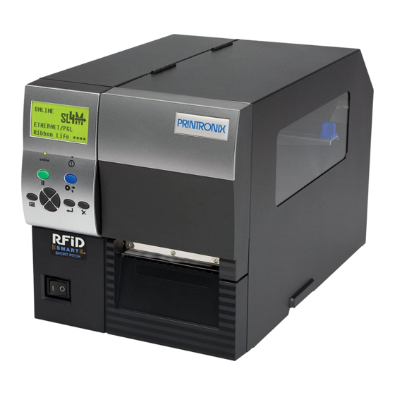
The default power-on state is online. Once the printer has successfully initialized, the ONLINE status indicator light illuminates, and the LCD indicates ONLINE, the printer model (SL4M/T4M), the printhead installed (203 or 305 dpi), the communication interface, and the emulation selected. -
Page 36: Control Panel
Chapter Controls and Indicators Control Panel The control panel is located on the front of the printer and includes an LCD, indicators, and control keys (buttons). LCD (Liquid Crystal Display) Online Indicator Fault Indicator Pause Key Feed Key Up Key Enter Key Menu Key Cancel Key... - Page 37 Control Panel Feed Key The Feed Key advances the media one label length in Online and Offline Mode. If there is data in the printer, the printer will print the data before ejecting the label. This key is inactive in all other modes. Menu Key In Online, Offline, or Fault modes, the Menu key causes the printer to enter the Menu mode and the top level menu icons to display.
- Page 38 Chapter Controls and Indicators Up Key In Menu mode (at the icon menu level), this key will move to the next row of icons. If on the bottom row it will move up the top row of icons. If at the top of the menu tree, pressing the Up key will go to the bottom of the menu tree.
- Page 39 Control Panel Left Key In Offline mode, this key adjusts the display brightness of the LCD. In Menu mode (at the icon menu level), this key will advance from one menu icon to the previous menu icon. If at the beginning of one row of icons it will move to the end of the other row of icons.
-
Page 40: Media Handling Modes
Chapter Media Handling Modes Media Handling Modes Before you load media, you must decide which media handling mode to use: • Tear-Off Strip (factory default). Printer prints on the media and sends it out the front until the print buffer is empty, then positions the last label over the tear bar for removal. -
Page 41: Printhead Pressure Adjustment
Media Thickness Adjustment Printhead Pressure Adjustment Media Thickness Adjustment Indicator Window Printhead Pressure Switch (blue) Metal Tab Printhead Balance Adjustment Dial This procedure adjusts the printhead pressure to accommodate media of different thicknesses. This will minimize printhead wear and optimize print quality. -
Page 42: Media Width Adjustment
Chapter Printhead Pressure Adjustment Media Width Adjustment Indicator Window Printhead Balance Adjustment Dial Media width adjustment allows you to vary printhead pressure along the platen from one end to the other. If the printhead pressure is out of balance, the printed image will be darker on one side of the label than the other and the media will travel in the direction with the least resistance. -
Page 43: Printhead Alignment
Printhead Alignment Printhead Alignment Align the printhead under the following conditions: to improve the print quality when running difficult media with major differences in thickness, when adjusting for media thickness (with the printhead pressure switch) did not yield adequate print quality, or when you replace the printhead. The printhead must be parallel with the platen for consistent image printing across the label. -
Page 44: Positioning The Media Sensors
Chapter Positioning the Media Sensors 3. Remove the printhead alignment tool (yellow screwdriver) from the tool clip. 4. Use the printhead alignment tool to turn the printhead alignment dial. Turn the printhead alignment dial UP for THICKER stocks and DOWN for THINNER stocks. - Page 45 Mark Sensor Indicator Gap Sensor Indicator (both sides) Media Sensor (both sides) Assembly Media Sensor Handle Media Sensing Media with Horizontal Black Marks or Inboard Notches 1. Use the media sensor handle to horizontally position the media sensor assembly so that the sensor indicators (embossed on both sides) are aligned with the reference marks on the media.
-
Page 46: Sensing Different Media Types
Chapter Positioning the Media Sensors Sensing Media with Gapped Liner 1. Use the media sensor handle to horizontally position the media sensor assembly so that the sensor indicators (embossed on both sides) are aligned with the reference marks on the media. 2. -
Page 47: Running Auto Calibrate
Running Auto Calibrate You can initiate Run Auto-Cal (Auto Calibrate) via the the SENSOR SETUP menu. NOTE: Verify that the Gap/Mark Sensor option (Gap, Mark, or Disable) matches the installed media. See “Sensing Different Media Types” on page 46. Check that the media sensors are horizontally positioned to permit sensing of the label length indicators. -
Page 48: Running Media Profile
Chapter Running Media Profile NOTE: The amount of media sampled during Auto Calibrate is based on the length of a label and transitions detected, without error, between a label and its label length indicators. 8. Press the (Pause) key until OFFLINE displays. 9. - Page 49 ↵ 4. Press to enter the SENSOR SETUP menu. ↵ 5. Press the Down key until Run Profile displays and then press ↵ (The printer will continue to print the profile until you press The printer will advance media and continue to print a dynamic profile image depicting the relationship of the label and any label length indicators detected.
-
Page 50: Running Manual Calibrate
Chapter Running Manual Calibrate Running Manual Calibrate Manual Calibrate should be performed only when the values derived from Auto Calibrate fail to improve the media sensors’ ability to sense label length indicators on the installed media. You must first enable Admin User in the PRINTER SETUP menu before accessing or initializing Run Manual Cal (manual calibrate) in the SENSOR SETUP menu. - Page 51 12. During the last step of Run Manual Cal, the printer advances the media and attempts to detect the label length indicators and stop at the Top-of-Form position. The Sensed Distance value will then display for one second. Calibration is successful when the Sensed Distance value correctly matches that of the installed media.
- Page 52 Chapter...
-
Page 53: Standard Interfaces
Standard Interfaces Overview This chapter describes the host interfaces provided with the printer. The printer interface is the point where the data line from the host computer plugs into the printer. The interface processes all communications signals and data to and from the host computer. Plus, with the Auto Switching feature, you can configure the printer to accept several interfaces at the same time. -
Page 54: Parallel Interface
Chapter Parallel Interface Parallel Interface Centronics Table 4. Centronics Interface Connector Pin Assignments Input Signals Output Signals Miscellaneous Signal Signal Signal DATA LINE 1 ACKNOWLEDGE CHASSIS GROUND Return Return DATA LINE 2 ONLINE GROUND Return Return DATA LINE 3 FAULT Spares Return Return... - Page 55 Centronics Centronics Interface Signals Table 5. Centronics Parallel Interface Signals Signals Purpose Data Lines 1 through 8 Provide eight standard or inverted levels from the host that specify character data, plot data, or a control code. Data Line 8 allows access to the extended ASCII character set.
-
Page 56: Ieee 1284
Chapter Parallel Interface IEEE 1284 The IEEE 1284 supports three operating modes, which are determined by negotiation between the printer and the host. Compatibility Mode This mode provides compatibility with Centronics-like host I/O (see Table 4). Data is transferred from the host to the printer in 8-bit bytes over the data lines. - Page 57 IEEE 1284 IEEE 1284 Interface Signals Table 6 lists each of the signals associated with the corresponding pins on the IEEE 1284 interface. Descriptions of the signals follow. Table 6. IEEE 1284 Signals Type of Mode Source of Data Compatible Nibble Byte Host...
- Page 58 Chapter Parallel Interface Table 6. IEEE 1284 Signals (continued) Type of Mode Source of Data Compatible Nibble Byte Signal Ground (Data 8) Signal Ground (PError, Select, nAck) Signal Ground (Busy, nFault) Signal Ground (nAutoFd, nSelectIn, nInit) Host nInit Printer NFault nDataAvail aDataAvail Not Defined...
-
Page 59: Serial Interface
RS-232 Serial Interface RS-232 nData Available / nPeripheral Request. Driven by the printer. Indicates the printer has encountered an error. (Data bits 1 and 5 in Nibble Mode.) 1284 Active / nAStrobe. Driven by the host. A peripheral device is selected. Host Logic High. - Page 60 Chapter Serial Interface Data Carrier Detect (DCD). Status signal to the printer. The ON condition is required for the printer to receive data. Data Terminal Ready (DTR). Control signal from the printer. Subject to configuration.
-
Page 61: Configuring The Printer
Configuring the Printer Overview This chapter provides information about: • Setting, saving, modifying, and printing configurations • Configuration menus Setting Printer Configuration Parameters Configuration parameters are set from the control panel or are retrieved from the printer’s memory. The parameters define how the printer will respond to command and interface signals from the host computer. - Page 62 Chapter Overview NOTE: In menus with numeric ranges of more than 50 numbers, hold down the right or left key for more than 2 seconds to move through the range in increments of 5. To move in increments of 1 again, release your hold on the right or left key.
-
Page 63: Selecting A Menu Option
Selecting a Menu Option Selecting a Menu Option ↵ To select an option, you need to press the key. By default, however, the ↵ key is “locked” when the printer is turned on to prevent accidental changes to the configuration menu. If you press the ↵ key when the key is locked, the ↵... -
Page 64: Changing Printer Settings
Chapter Hidden Menus Changing Printer Settings You can change (or “configure”) printer settings, such as print speed or emulations, through the control panel as follows: 1. Press the key to enter the Menu configuration. MEDIA SETUP is selected. ↵ 2. Press the key to enter the MEDIA SETUP menu. -
Page 65: Menu Overview
8. If there are more submenu values or options you want to change, use the ↵ ,Up, Down, Left, and Right keys to access the value and the key to select it. At any time, you may press the key to return to the Main menu. -
Page 66: Main Menu
Chapter Main Menu Main Menu MEDIA SENSOR PRINTER EMULATION SETUP SETUP SETUP (page 68) (page 84) (page 106) (page 91) Print Intensity Gap/Mark Sensor Select PAA: Status Print Speed Run Auto-Cal Emulation Setup Power Saver Time Print Mode Run Profile xxx Diagnostics Pwr Save Control Media Handling... - Page 67 INTERFACES RFID CONFIGURATION DIAGNOSTICS (page 117) (page 141) (page 144) Host Interface Save Config. Printer Tests Refer to the RFID ETHERNET PORT Load Config. Test Count Labeling Reference ETHERNET SETTING Print Config. Software Build Manual. WLAN SETTING Delete Config. Feature File Parallel Port Power-Up Config.
-
Page 68: Media Setup Menu
Chapter MEDIA SETUP Menu MEDIA SETUP Menu MEDIA SETUP (from page 66) Print Intensity Print Speed Print Mode Media Tear Off Handling Adjust Continuous 4 ips* Transfer* Tear-Off Strip* Standard* 0.00* -15 to 15 1 ips to 10 ips Direct Peel-Off Tear-Off -1.00 to 0.20... -
Page 69: Media Setup Submenus
MEDIA SETUP Submenus MEDIA SETUP Submenus Print Intensity This option specifies the level of thermal energy from the printhead to be used for the type of media and ribbon installed. Large numbers imply more heat (thermal energy) to be applied for each dot. This has a significant effect on print quality. - Page 70 Chapter MEDIA SETUP Menu • Cut. When the optional media cutter is installed, it automatically cuts media after each label is printed or after a specified number of labels have been printed when a software cut command has been issued. It cuts continuous roll paper, labels, or tag stock.
-
Page 71: Label Length
MEDIA SETUP Submenus Tear Off Adjust This option represents the distance to advance (+ shift) or pull back (– shift) the stop position of a label when Tear-Off Strip, Peel-Off, or Cut media handling option is enabled. The allowable range is -1.00 inches to + 0.2 inches, in .01 inch increments. - Page 72 Chapter MEDIA SETUP Menu When the Logical Label Length is greater than the Physical Label Length and Clip Page = Disable, the printer will continue to print the image onto the next physical label and ignore the gap or mark based on the label length value set in the MEDIA SETUP menu.
- Page 73 MEDIA SETUP Submenus Orientation This menu item selects the image orientation to be used when printing the label. • Portrait. Portrait refers to vertical page orientation, where the height of a page is greater than its width. The top edge of the image is parallel to the leading edge of the media.
- Page 74 Chapter MEDIA SETUP Menu • Inv. Portrait. Inverse Portrait refers to vertical page orientation, where the height of a page is greater than its width. The top edge of the image is parallel to the trailing edge of the media. The following illustration is an example, with the operator viewing the front of the printer.
- Page 75 The IGP/Auto Label Mapping feature allows backward compatibility of programs written for P5000 line-matrix printers using the Printronix PGL graphics language. It allows the printer to print two-up (or other multi-up) labels. Instead of printing multiple labels across the printer, it prints the leftmost label and the rightmost label, so the printout will be twice as long but half as wide.
- Page 76 Chapter MEDIA SETUP Menu Example 2: Uneven Number Case Problem: A file has been constructed with three horizontally adjacent 2” labels. The user now desires to use this file with a printer that has a 4” physical width. Solution #1: The user sets Auto Label Width to 4” (the width of two labels), configures the Num Auto Labels to 2, and enables the Auto Label Mapping feature.
- Page 77 MEDIA SETUP Submenus Example 3: Past Maximum File Width Problem: A file has been constructed with three horizontally adjacent 4” labels. The user now desires to use this file with a printer that has a 8” physical width. The user should have used a solution similar to one of the solutions in the section above, but the user erroneously enters an Auto Label Width of 12”...
-
Page 78: Print Direction
Chapter MEDIA SETUP Menu Num Auto Labels The desired number of labels to be printed vertically adjacent on the form. The value is selectable with a range of 1 through 40 labels. The factory default is 2. Slew Speed Ctrl The speed at which the printer moves media without actually printing on it. - Page 79 The range is 0.1 to 60.0 seconds, and the factory default is 0.1 second. NOTE: For the SL4M Short Pitch RFID printer, the default is 1.0 second. Label Missing If enabled causes the Label Taken Sensor to first check for the presence of a printed label at the tear bar for Peel Off and Tear Off Media Handling Modes only.
- Page 80 Chapter MEDIA SETUP Menu Clip Page This option determines how the printer handles images that are too large for one physical page length when using gap or black mark media. • Enable (factory default). When the user-selected page length is greater than the physical page length, the printer clips the excess data to fit the physical page.
-
Page 81: Ribbon Low
MEDIA SETUP Submenus Fault Reprint This option determines how the printer handles data that was printing when an error occurred. • Disable (factory default). The printer will not reprint the label that was printing when the error condition occurred. • Enable. - Page 82 Chapter MEDIA SETUP Menu TOF Detect Fault Allows selection of three different TOF (Top-of-Form) detection faults. NOTE: The correct Label Length value, equal to the physical length of the installed label, must be entered MEDIA SETUP menu. • 3 Labels (factory default). The printer displays a Gap Not Detected fault and stops printing when media has advanced a distance equal to three or more times the Label Length value set in menu.
- Page 83 TOF Adjust Mode • Disable (factory default). This option disables the “TOF Adjust” distance set using the TOF Adjust menu (see TOF Adjust below). • Enable. This option enables the “TOF Adjust” distance set using the TOF Adjust menu (see TOF Adjust below). TOF Adjust This option sets the distance from the Top Of Form (TOF) that is left blank (unprinted) after a label has been removed in Tear-Off Strip.
-
Page 84: Sensor Setup Menu
Chapter SENSOR SETUP Menu SENSOR SETUP Menu SENSOR SETUP (from page 66) Gap/Mark Run Auto-Cal Run Profile Sensed Gap/Mark Sensor Distance Thresh Gap* 0.00 inches* 000 to 255 Disable 0.01 inches to xx inches Mark Paper Out Run Manual Pwr Up Head Online Thresh... -
Page 85: Sensor Setup Submenus
The Top-of-Form depends on the Mark TOF Detect menu. NOTE: For the SL4M Short Pitch RFID printer, the default is Mark. Run Auto-Cal (Auto-Calibrate) This feature is used to set the sensitivity and reliability of the Media Sensor in detecting gaps, notches, holes, or black marks on the installed media, as well as a paper out condition. - Page 86 Chapter SENSOR SETUP Menu Run Profile This feature provides a graphical printout showing the relationship of the Paper Out Threshold and the Gap/Mark Threshold. The profile printout assists you in setting the thresholds for difficult media. This includes preprinted labels, and labels with poor gap/media dynamic range. When selected, the printer will advance media and print the media profile along the length of each label.
- Page 87 SENSOR SETUP Submenus Run Manual Cal Run Manual Cal is another method of improving the printer’s media sensing and is only used when Auto Calibrate has failed or the Gap/Mark Threshold or Paper Out Threshold values derived from Auto Calibrate do not improve the media sensors’...
- Page 88 If the printer is in Peel mode, the calibration will not be done unless “Cal in Peel Mode” is set to enable. 2. For the SL4M Short Pitch RFID printer, the default is Disabled. Online Auto-Cal The options for Online Auto-Cal are: •...
- Page 89 SENSOR SETUP Submenus • Enable. When the leading edge of a gap is detected, the printer ignores the first 90% of the gap length value specified in the Gap Length menu option. The result is that cross perforations or unusual media discrepancies within the gap are filtered out, allowing the printer to reliably detect the actual leading edge of the next label and use it as the TOF position.
- Page 90 Chapter SENSOR SETUP Menu Use Label Length Determines whether or not the Label Length value set in the MEDIA SETUP menu is used during Run Auto-Cal. • Disable (factory default). Run Auto-Cal relies exclusively in its ability to detect varying transitions between labels and gaps, notches, holes, or black marks while advancing media during the calibrate process to determine Sensed Distance.
-
Page 91: Emulation Menu
Mark Lead Edge. Leading edge or start of black line denotes TOF. NOTE: 1. This option applies only when Gap/Mark Sensor is set to Mark. 2. For the SL4M Short Pitch RFID printer, the default is Mark Lead Edge. EMULATION MENU... - Page 92 Chapter EMULATION MENU Alphanumeric data can appear as prepositioned “fixed” information (entered when the form is created), be overlayed onto the form (positioned in a specific location after the form is created), or may be dynamically merged with the form. Selectable Bar Codes provide you with the appropriate bar code for your application using standard wide-to-narrow ratios.
- Page 93 Overview EMULATION (from page 66) Select Emulation Diagnostics Setup PGL* STGL IEGL Setup Setup Setup See page 94 or Refer to the ZGL Refer to the TGL refer to the PGL Programmer’s Programmer’s Diagnostics Diagnostics Programmer’s Reference Manual Reference Manual Reference Disable* Manual...
- Page 94 Chapter EMULATION MENU PGL Setup SETUP (from page 91) Character Standard Select LPI Define CR Define LF Group Sets Code Code See page 96 0) ASCII* 9) Spanish CR = CR* LF = LF* 1) German 10) Italian 1 to 1000 CR = CR + LF LF = CR + LF 2) Swedish...
- Page 95 Overview PGL SETUP (continued from page 94) I-2/5 User-Def Lead Trunc Descenders Selection Compatbl. Ratio PDF Dist Dyn Data Always* Leading Zero* Disable* Enable* 0.10 Inches* Disable* Never Trailing Space Enable Disable 0.01 inches to Enable Only With PDF X2 DPD 0.10 inches Modulo 7 CD Vertical...
- Page 96 Chapter EMULATION MENU Character Group (from page 94) Standard Arabic Sets Cyrillic Sets European Greek Sets Sets* Sets 0) ASCII* ASMO 449* Code Page 866* Latin 2 8859-2* DEC 256 Greek* 1) German ASMO 449+ Cyrillic CP 437 Code Page 852 ELOT 928 Greek 2) Swedish ASMO 708...
-
Page 97: Emulation Submenus
EMULATION Submenus EMULATION Submenus Select This function allows you to activate any resident emulation listed in the menu. The factory default is PGL. There are two methods for selecting the desired emulation: • Select the emulation under the Select menu option and save it as Power-up Config. - Page 98 Chapter EMULATION MENU PGL Setup Submenus NOTE: The submenu descriptions do not include ZGL, TGL, IGL, STGL, DGL, MGL, and IEGL emulations. Character Group and Character Sets This menu item selects the character set used by the printer. See page 96 for the available character sets.
- Page 99 EMULATION Submenus Auto Uppercase This parameter enables the printer to print text in all uppercase when using the ALPHA command. • Disable (factory default). The printer will print text in upper and lowercase. • Enable. The printer will print text in uppercase only. Slash 0 This parameter allows you to print the numeral “0”...
- Page 100 Chapter EMULATION MENU Var Form Adjust This specifies an amount (in tenths of inches) to add to the length of variable- length forms. Variable-length forms use a semicolon at the end of the CREATE command: ~CREATE;<FORMNAME>;0. Var Form Type • Add Nothing (factory default).
- Page 101 EMULATION Submenus Power on IGP/PGL You can set the PGL feature so that it is enabled or disabled when the printer is powered on. • Enable (factory default). IPG/PGL is enabled when the printer is powered on. (The PGL feature is initialized in Normal mode). •...
- Page 102 Chapter EMULATION MENU Select Char This parameter selects which character to discard when Ignore Mode is enabled. • 0 (the default) • 0 - 255. Any character from 0 to 255 in decimal. Do FF at TOF Determines whether the printer, with media already set at the TOF (Top-of- Form) position, will advance media to the next TOF position upon receipt of an FF command.
- Page 103 EMULATION Submenus PGL Normal This option determines whether PGL passes the text data in Normal mode or whether PGL will print the data text itself. • LP+ Menu (factory default). PGL will pass the text data to the menu only in default setting state.
- Page 104 Chapter EMULATION MENU User-Def Ratio This option allows you to ignore the user-defined barcode ratio and replace it with the default ratio (X1). • Enable (factory default). Allows the user-defined barcode ratio. • Disable. The user-defined barcode ratio will be replaced with the default ratio (X1).
- Page 105 Preparser Allows users to send the Preparser command to the printer through any port. • Disable (factory default). Does not use the Preparser command. • Enable. Sends the Preparser command Storage Select Allows the user to map the parameter DISK to either EMC (Expanded Memory Cartridge) or PC Flash (PC Board Flash).
-
Page 106: Printer Setup Menu
Chapter PRINTER SETUP Menu PRINTER SETUP Menu PRINTER SETUP (from page 66) Power Saver Pwr Save Display Alarm Power-up PAA: Status Time Control Language State 15 minutes* Enable* English* Online* Disable* 30 minutes Disable German Cont. Beep Offline Enable 45 minutes French 60 minutes Italian... - Page 107 PRINTER SETUP (continued from page 106) Print EMC FFS Optimize& Auto Locking Set Lock Key Reboot File List Overwrite Files* Disable* Enable* Enable Disable View EMC Files Delete Files Flash Avail. Max Font Max Cache Max Cached Standard Bold Extra Bold Buffer Memory Char...
-
Page 108: Printer Setup Submenus
Chapter PRINTER SETUP Menu PRINTER SETUP Submenus PAA: Status See “Printronix Application Adapter” in the PrintNet Enterprise Suite User’s Manual. • Disable (factory default). The printer disables the use of PAA functionality. • Enable. The printer enables the use of PAA functionality. -
Page 109: Cancel Key
PRINTER SETUP Submenus PTX Setup Parse • Enable (factory default). Will parse and execute the PTX SETUP commands. • Ignore. Will parse the PTX SETUP commands but not act on them. • Disable. Will not parse the PTX SETUP commands so they will print out as text. - Page 110 • Default (factory default). Use for optimum performance. • Laser. Forces the output to correspond with the Printronix laser line of printers. • P5000. Forces the output to correspond with the P5000 line of line matrix printers.
- Page 111 PRINTER SETUP Submenus Del Set from RAM This option deletes the downloaded overlay set(s) from RAM. Ld Set at PwrUp This option loads the downloaded overlay set from flash memory to RAM at Power Up. The options are Disable (factory default) and Enable. Main FFS •...
- Page 112 Chapter PRINTER SETUP Menu Optimize&Reboot Reclaims flash space from deleted flash files. After pressing ↵ wait for the printer to reboot. NOTE: The Optimize feature will optimize both the Main and Extended Flash file system (if present) and remove any deleted file names indicated by “?Filename”.
- Page 113 PRINTER SETUP Submenus Max Font Buffer The maximum amount of DRAM allocated for downloading fonts (TrueType, Scalable, or Bitmap). DRAM allocation will not take effect unless you save it in a configuration and the printer is powered up with that configuration. The range is 100 to 1800 Kbytes, and the factory default is 1100 Kbytes.
- Page 114 Chapter PRINTER SETUP Menu For example, with a print head that prints at 203 dpi you would use the following formula: 203 x 203 x 1 x 1 = 5,151 Therefore, select a value that is equal to or greater than 5,151. The closest available value is 6 KBytes.
- Page 115 PRINTER SETUP Submenus Tall Characters Increases the point height of resident Intellifont characters. • Disable (factory default). Standard resident font character point height is maintained. • Enable. Increases the point height of resident Intellifont characters approximately 10%. Batch Counter Displays the number of pages remaining in a print job. •...
- Page 116 Chapter PRINTER SETUP Menu Bot Line Display • Ribbon Life (factory default). The last line of the display shows the ribbon life. When the printer is online and after a few labels have been fed, "Ribbon Life" and 1 to 4 asterisks will display on the last line of the LCD indicating the approximate amount of ribbon remaining on the supply spindle, based on a standard 450m ribbon.
-
Page 117: Interfaces Menu
INTERFACES Menu INTERFACES (from page 67) Host ETHERNET WLAN ETHERNET Interface SETTING PORT SETTING Auto Switching* Timeout* IP Address Internat. Mode IP Address Centronics 10 sec* Subnet Mask Disable* Subnet Mask Serial 1-60 sec Gateway Address Enable Gateway Address IEEE 1284 Switch Out On MAC Address Auth Method... - Page 118 Chapter INTERFACES Menu INTERFACES (con’d from page 117) Parallel Centronics IEEE 1284 Serial Printer Mgmt 1, 4 Port Port Port Port Type Data Bit 8 Prime Signal Buffer Size in K See page 119 See page 120 IEEE 1284* Enable* Disable* Disable Disable...
- Page 119 Serial Port (from page 118) Baud Word Stop Bits Parity Data Buffer Size Rate Length Protocol in K 9600 BAUD* None* XON/XOFF* 600 BAUD to ETX/ACK 1 - 16 115200 BAUD Even ACK/NAK Mark Series1 1Char Sense Series1 2 Char ENQ/ACK Trickle Timeout...
- Page 120 Chapter INTERFACES Menu Printer Mgmt (from page 118) PNE Port Mgmt Select Port Baud Rate Word Stop Bits Protocol Length Disable* PXML* Debug* 9600 BAUD* Serial Host 2400 BAUD TO Ethernet 115200 BAUD Parity Modem Modem NUM Modem Dial PNE Port Status Method Number...
-
Page 121: Interfaces Submenus
INTERFACES Submenus INTERFACES Submenus Host Interface This option allows you to send print jobs through any interface with autoswitching selected as host interface. It also allows a particular interface from the menu to be selected. The options are Auto Switching (factory default), Centronics, Serial, IEEE 1284, and Ethernet. - Page 122 Chapter INTERFACES Menu • Subnet Mask. This item allows you to set the Subnet Mask for the TCP/IP protocol in four three-digit segments (SEG1 through SEG4). If the Subnet Mask is assigned by BootP, Arp or DHCP, it is dynamic and read-only.
- Page 123 INTERFACES Submenus • BootP You can enable or disable the BootP protocol using this option, but consult your administration for the appropriate setting. The options are Enable (factory default) and Disable. NOTE: When changing the BootP option, the printer resets the NIC when the printer is placed online.
- Page 124 Chapter INTERFACES Menu • Job Control • Standard (factory default). The NIC waits for the entire job to be received before it indicates the job is done. • Enhanced. The NIC waits for the entire job to be printed before it indicates the job is done.
- Page 125 INTERFACES Submenus • Subnet Mask. This item allows you to set the Subnet Mask for the TCP/IP protocol in four three-digit segments (SEG1 through SEG4). If the Subnet Mask is assigned by BootP, Arp or DHCP, it is dynamic and read-only.
- Page 126 Chapter INTERFACES Menu • BootP You can enable or disable the BootP protocol using this option, but consult your administration for the appropriate setting. The options are Enable (factory default) and Disable. NOTE: When changing the BootP option, the printer resets the NIC when the printer is placed online.
- Page 127 INTERFACES Submenus • Antenna. The type of antenna used: • Primary (factory default). Select when you want to use the Primary antenna on the server. • Auxiliary. Select when you want to use the Auxiliary antenna on the server. • Power Mgmt.
- Page 128 Chapter INTERFACES Menu • Auth Method. This feature allows the user to select the authentication method used for the wireless network interface. • Open (factory default). Selects open authentication. • Shared. Selects shared key authentication. • WEP Key 1 through 4. These are the individual characters of the encryption key.
-
Page 129: Parallel Port
INTERFACES Submenus Parallel Port • Port Type. This menu item selects the type of printer parallel port interface to be used with the host. The options are IEEE 1284 (factory default), Disable, and Centronics. • Data Bit 8 • Enable (factory default). The PI line is not passed directly from host to printer;... - Page 130 Chapter INTERFACES Menu The selected value is the time that the printer waits before getting the next byte of data from the host. The Trickle Time value should be less than the host time out value, but not too much shorter or else the printer fills up its buffer too fast.
- Page 131 INTERFACES Submenus • Offline Process • Disable (factory default). When set to disable, the printer does not process parallel/network data while offline. • Enable. When set to enable, the printer continues to process (but not print) the current network/parallel job while the printer is offline until the printer's buffer is full.
- Page 132 Chapter INTERFACES Menu • Latch Data On. Specifies whether the data is read on the leading or trailing edge of the data strobe signal. The options are Leading (factory default) and Trailing. • Prime Signal • Disable (factory default). A prime signal from the host is ignored. •...
-
Page 133: Serial Port
INTERFACES Submenus Serial Port • Baud Rate. Sets the baud rate of the serial interface in the printer. Baud rate is the speed at which serial data is transferred between the host computer and the printer. The options for the RS-232 interface are 600, 1200, 2400, 4800, 9600, 19200, 38400, 57600, and 115200 Baud. - Page 134 Chapter INTERFACES Menu every two seconds while the number of valid bytes in the buffer is less than 75 percent of the buffer size. If a poll character is received (configurable from the Poll Character xx Hex option on the front panel from hex 0 through FF), the printer will send a response character n milliseconds later (configurable from the Poll Character xx MS on the front panel from 0 through 30).
- Page 135 INTERFACES Submenus • ENQ/ACK. Enquiry/Acknowledge. The host controls the flow of communication to the printer by sending a block of data and ending the block with an Enquiry (ENQ) character. When the printer receives the ENQ Character, it acknowledges the ENQ, thereby acknowledging it has received the entire block of data.
- Page 136 Chapter INTERFACES Menu • Report Status. When a fault condition occurs in the printer, normally only the active port reports the fault to the host. With this menu item enabled, the port will report any fault even when it is not the current, active port. The options are Disable (factory default) and Enable.
- Page 137 INTERFACES Submenus • One Char Enquiry. The One Char Enquiry mode uses the Poll Character to detect a request from the host and sends a response back to the host. This option also allows you to turn on and off this feature. Table 10.
- Page 138 Chapter INTERFACES Menu Table 12. ENQ Status Byte Printer Status Set when the label has printed. Set when the label is presented. Set while the printer is online. Always set. Set printing in the batch mode. Set during a Ribbon fault. Set during a Paper Out fault.
- Page 139 INTERFACES Submenus • Baud Rate. Sets the baud rate of the serial interface used to communicate to the PNE. Baud rate is the speed at which serial data is transferred between the PNE and the printer. The options for the RS-232 interface are 600, 1200, 2400, 4800, 9600, 19200, 38400, 57600, and 115200 Baud.
- Page 140 Chapter INTERFACES Menu • PNE Port Timeout. If the PNE has not communicated to the printer within a timeout period, the PNE session closes. The factory default is 100 seconds. The range is from 1 to 255 seconds. • Status Port Number. This is the Ethernet Port number the emulations can use to communicate status to the host computer.
-
Page 141: Configuration Menu
CONFIGURATION MENU CONFIGURATION (from page 67) Save Load Print Delete Power-Up Protect Config. Config. Config Config. Config. Configs. Cfg 1* Factory* Current* Cfg All* Factory* Disable* Cfg 1 to Cfg 8 1 to 8 Factory 1 to 8 Enable Power-Up 1 to 8 1 to 8 Name... -
Page 142: Configuration Submenus
Chapter CONFIGURATION MENU CONFIGURATION Submenus Save Config This option allows you to save up to eight unique configurations to meet different print job requirements. This eliminates the need to change the parameter settings for each new job. The configurations are stored in memory and will not be lost if you turn off the printer. - Page 143 CONFIGURATION Submenus Name Config 1 to Name Config 8 You may specify a 15-character name which can be used to refer to a configuration. The name you enter for a configuration will be used in the Load Config., Save Config., Print Config., Delete Config., and Power-Up Config. menus.
-
Page 144: Diagnostics Menu
Chapter DIAGNOSTICS Menu DIAGNOSTICS Menu DIAGNOSTICS (from page 67) Printer Test Software Feature Hex Dump Auto Tests Count Build File Mode Dump Checkerboard* 5 Pages* XXXXXX XXXXXX- XXX Disable* Disable* Grey 10 Pages Enable Enable Grid Continuous Current Config 1 Page 2 Pages Left Test Right Test... -
Page 145: Diagnostics Submenus
DIAGNOSTICS Submenus DIAGNOSTICS Submenus Printer Tests The printer tests below allow you to check for proper printer operation and print quality: • Checkerboard (factory default). This pattern helps identify marginal printhead elements, quality of edge sharpness, and uneven print quality. •... -
Page 146: Hex Dump Mode
“autodbg1.dbg” or “autodbg2.dbg” in the printer file system. This file can be uploaded to the host using the PrintNet Enterprise Suite application. Upon receipt of this file, it should be sent to the Printronix Customer Support Center for review and evaluation. - Page 147 DIAGNOSTICS Submenus PrintHead Usage Displays the length of media actually printed since the last Reset Head Data operation. This value is set to zero at the factory after burn-in testing. Head On Time Displays the time that power has been applied to the printhead since the last Reset Head Data operation.
-
Page 148: Saving A Configuration
Chapter Saving a Configuration Saving a Configuration You can save up to eight different configurations to meet eight unique print job requirements. These configurations are saved and stored in the printer and are not lost when the printer is turned off. NOTE: If the Protect Config. -
Page 149: Auto Save Configuration
DIAGNOSTICS Submenus Auto Save Configuration Auto Save Functionality The Auto Save Configuration function is triggered when the operator has made a change to a menu that is normally saved as part of a printer configuration and attempts to go online without saving these changes to a configuration. -
Page 150: Specifying A Power-Up Configuration
Chapter Specifying a Power-Up Configuration The active option is highlighted. The operator can use the Up and Down keys to scroll through the different options. The keys will loop at the top and bottom ↵ options. The (Enter) key selects the highlighted option. The printer will go Online after performing the selected option. - Page 151 DIAGNOSTICS Submenus 7. Press the ↵ key to select Enable. An asterisk appears after Enable. Setting Admin User to Enable allows the user to see hidden submenus. 8. Press the key go to the main menu. 9. Press the Right key until the following displays: CONFIGURATION ↵...
-
Page 152: Modifying A Saved Configuration
Chapter Modifying a Saved Configuration Modifying a Saved Configuration You can change a saved configuration by rewriting over it. For example, you can modify Config. 1, shown below. Suppose you want to keep all the settings but you want to select the parallel Centronics interface instead of the IEEE 1284 interface. - Page 153 DIAGNOSTICS Submenus 4. Before saving the modified configuration, you must delete the original configuration if the Protect Config. option is enabled. a. Press the Up or Down keys until the following message displays: Delete Config. b. Press the Left or Right keys to cycle through the options (1-8). When the desired number displays, press the ↵...
-
Page 154: Printing A Configuration
Chapter Printing a Configuration Printing a Configuration We recommend that you print and store your configurations for future reference. The printout provides a list of the parameters that were set when you configured the printer. To print a configuration: 1. Press the key to enter the Main menu. -
Page 155: Loading A Saved Configuration
DIAGNOSTICS Submenus Loading a Saved Configuration Method 1 1. Press the key to place the printer offline. 2. Press the Up key. The following message displays: Load Config. Cfg1* 3. Press the Up key until the desired configuration displays. ↵ 4. - Page 156 Chapter Loading a Saved Configuration...
-
Page 157: Downloading Software
Downloading Software Loading Flash Memory Flash memory is contained in a SIMM (single in-line memory module) located on the controller PCBA. Printer control languages (the “emulations”) and printer operating system software are loaded into flash memory at the factory, but there are occasions when you may have to load this software: •... -
Page 158: Downloading Software With The Firmware Download Utility
Chapter Downloading Software with the Firmware Download Utility Downloading Software with the Firmware Download Utility The Firmware Download Utility (FDU) allows you to load program files into the printer with an easy to use graphical interface. The FDU is a utility program included on the CD that comes with the printer. -
Page 159: Downloading Software Through The Parallel Port
13. Double-click the FDU.jar file (for command line prompt users, type java -jar fdu.jar<Enter>). It will launch in its own window. Use the FDU to enter the emulation part number, to select the I/O connection and its corresponding settings, and to initiate the download. IMPORTANT Do not interrupt the downloading process once it has started. -
Page 160: Downloading Software Through The Nic
Chapter Downloading Software through the NIC 14. Enter the following command: filename.exe -pb<Enter> where filename.exe is the file name you noted in step 10. This command takes the file on the hard drive and copies it as a binary file into the flash memory on the printer controller board. - Page 161 11. At the command prompt type: C:<Enter> cd \download<Enter> 12. Enter the following command: filename.exe -n xxx.xxx.xxx.xxx<Enter> where filename.exe is the file name you noted in step 8 and xxx.xxx.xxx.xxx is the IP address of the printer. This command takes the file on the hard drive and copies it as a binary file into the flash memory on the printer controller board.
-
Page 162: Downloading Software Through The Nic Using Ftp
Chapter Downloading Software through the NIC Using FTP Downloading Software through the NIC Using FTP IMPORTANT To load software through the NIC, you need the IP Address of the printer and the flash memory must contain basic printer code. If the flash memory was replaced, or if a download was interrupted (e.g., by a power outage), you must load software through the parallel port. - Page 163 16. Once logged in, type the following sequence at the command prompt to download the filename.prg file to the printer: cd dest<Enter> cd d1prn<Enter> bin<Enter> put filename.prg<Enter> where filename.prg is the file name you noted in step 8. IMPORTANT Do not interrupt the downloading process once it has started. Interrupting a download will leave the flash memory on the controller PCBA and NIC incompletely loaded, and the printer may not boot up.
-
Page 164: Downloading Software Through The Usb Port
Chapter Downloading Software through the USB Port Downloading Software through the USB Port Normally the host communicates with the printer’s USB port with a Windows driver. To download a file using the USB Port, it needs to be remapped. To download software through the USB Port, perform the following steps: 1. -
Page 165: Downloading Software Through The Printronix Windows Driver
Downloading Software through the Printronix Windows Driver Downloading Software through the Printronix Windows Driver The Printronix Windows Driver contains an option that allows you to download software to the printer. To download software to the printer, perform the following steps: 1. -
Page 166: Downloading Software If Flash Contains Only Boot Or Corrupt Code
14. After the software successfully loads into flash memory, the printer will reset itself. NOTE: For SL4M printers, the RFID reader firmware will not upgrade using this download method. If the RFID reader needs to be upgraded, repeat the download process using one of the methods described... -
Page 167: Using Truetype Fonts
PRINTER SETUP Optimize & Reboot. Printronix Windows Driver A TrueType font can be downloaded from a PC through the Printronix Windows Driver. 1. Load the Printronix Windows driver provided with your printer on the Manuals and Utilities CD on Windows 2000/XP. -
Page 168: Pgl Emulation (Online)
Chapter Downloading TrueType Fonts PGL Emulation (Online) A TrueType font can be loaded by creating a file that appends a PGL command to the font and then sending that file to the printer. Use the PGL FONTLOAD command: ~FONTLOAD;FontName;FontSize;Location where FontName - TrueType font name, e.g. - Page 169 Download Mode Header For EMC Flash 1. Start a Command prompt window. 2. Copy cnvt2fls.exe and addttemc.bat from your startup CD to your working directory. 3. In your working directory, include the TrueType font file in .ttf format (e.g., arial.ttf). 4.
- Page 170 Chapter Downloading TrueType Fonts 8. Start a command prompt session. (The Start Menu icon is usually labeled Command Prompt or MS-DOS Prompt.) 9. Make note of the file name with the .dwn extension of each file you want to download to the printer. 10.
-
Page 171: Ptx_Setup
PTX_SETUP 13. Press (Pause) key to place the printer online and return the printer to normal operation. Download TrueType Fonts via the Ethernet Using FTP 1. Put the printer into download mode. See “Download Mode” on page 168. 2. Use FTP to transfer the binary font file (.dwn instead of .prg) to the printer through the Ethernet. -
Page 172: Filename Extensions Not Shown In Menus
Chapter Filename Extensions Not Shown in Menus Filename Extensions Not Shown in Menus Files with the one of the filename extensions below (upper or lower case) are considered system files and are not shown in the View File List or Delete Files menu. - Page 173 Labeling Applications Example: ~CREATE;FORM ISET;’UTF8’ FONT;NAME ARIAL.TTF ALPHA 10;10;2;2;$UTF-8 data$ STOP ~EXECUTE;FORM;1 To Print Double Byte Characters (DBCS) You can print double byte (DBCS) characters using the ISET or SYMSET command to select DBCS character set with a non-DBCS printer (without a DBCS font cartridge).
- Page 174 Chapter Select and Print Downloaded TrueType Fonts...
-
Page 175: Routine Care And Troubleshooting
Routine Care and Troubleshooting Cleaning Depending on the media used, the printer may accumulate residues (media dust, adhesives, etc.) as a by-product of normal printing. To maintain top printing quality, remove these residues by cleaning the printer periodically. WARNING Set the printer power switch to O (Off) prior to performing any cleaning tasks. -
Page 176: Interior Cleaning
• Cleaning Agent - Clean the printhead using a Printhead Cleaning Pen, Printronix PN 203502-002, or an Isopropyl Alcohol Wipe, Printronix PN 254945-901. • Schedule - Clean the printhead each time you install a new roll of ribbon (thermal transfer print mode) or when you install a new roll or box of media (direct thermal print mode). - Page 177 Cleaning the Printhead, Platen Roller, Media Sensors, and Media Damper NOTE: Even after a thorough cleaning with a Printhead Cleaning Pen or Alcohol Wipe, you may still see printouts with voids or streaks. This may be the result of baked-on ribbon resin that can be hard to remove when normal cleaning cycles are not maintained.
- Page 178 Chapter Cleaning Printhead Heating Elements (underneath, not shown) Deck Lock Lever Printhead Assembly Media Sensor Assembly Printhead Release Lever Platen Roller Print Element Figure 3. Cleaning the Printhead, Platen Roller, and Media Sensors...
- Page 179 Cleaning the Printhead, Platen Roller, Media Sensors, and Media Damper Media Damper Cleaning The media damper and its width guides can accumulate parts of labels, adhesive and paper dust residue that can prevent the proper guiding of labels. • Cleaning Agent - Use an isopropyl alcohol wipe or isopropyl alcohol on a clean cloth.
-
Page 180: Printer Tests
Chapter Printer Tests 13. Test the printer cutting operation by selecting one of the test patterns to print. Select Printer Tests in the DIAGNOSTICS menu (see “DIAGNOSTICS Menu” on page 144). Printer Tests A sequence of automatic tests is performed during printer power-up. If any faults are detected at that time, a fault message will display. -
Page 181: Data Exchange
Data Exchange Data Exchange Many things can cause data loss or communications problems. This section suggests some ways to isolate these problems and determine their cause. Handshaking Handshaking is the exchange of signals between two computers (or a computer and a peripheral input or output device) to indicate the status of the data being transferred. -
Page 182: Controlling Print Quality
Chapter Troubleshooting Common Situations Controlling Print Quality Four factors have the greatest effect on print quality: • The amount of heat applied by the printhead elements (print intensity) • The speed at which media is moving under the printhead (print speed) •... -
Page 183: Replacing The Printhead
Replacing the Printhead 1. Set the printer power switch to O (Off). WARNING Always unplug the printer power cord from the printer or power outlet before doing any installation procedure. Failure to remove power could result in injury to you and damage the equipment. When applicable, you will be instructed to apply power. - Page 184 Chapter Replacing the Printhead CAUTION To prevent electrostatic damage to electronic components, ground yourself by touching an unpainted part of the printer frame before handling and installing the printhead. 6. Touch an unpainted part of the printer frame before touching the printhead.
-
Page 185: Restore The Printer To Operation
Restore the Printer to Operation 1. Inspect the light brown area of the printhead for smudges or fingerprints. If necessary, gently clean the light brown area with a soft, lint-free cloth (or a cotton swab) moistened with isopropyl alcohol. 2. Install the ribbon and media (e.g., paper, label, or tag stock material). 3. -
Page 186: Diagnostics For E0Xx, Bad Nvm, Or Ill Nvm Errors
“NOVRAM ERR”, reboot the printer and continue. If this situation persists, invoke a diagnostic option that will capture the failure dump in a flash file that can be later uploaded from PrintNet Enterprise Suite and sent to Printronix Customer Support Center (see page 273) for further analysis. -
Page 187: Solving Other Printer Problems
Solving Other Printer Problems Solving Other Printer Problems Table 14. Printer Problems and Solutions Symptom Solution/Explanation Communications Failures. 1. Check the interface cable. 2. Check the configuration to ensure the correct interface is enabled. 3. Verify the printer is receiving data by viewing the flashing Online indicator on the control panel. - Page 188 Chapter Diagnostics for E0xx, Bad NVM, or ILL NVM Errors Table 14. Printer Problems and Solutions (continued) Symptom Solution/Explanation LCD message display is This message informs the user that the printer has received illuminated and the printer data, but no valid commands were found. This typically occurs appears to be working, but when an incorrect emulation or SFCC was selected.
- Page 189 Solving Other Printer Problems Table 14. Printer Problems and Solutions (continued) Symptom Solution/Explanation POWER FAILURES Printer fails to turn on, the 1. Check that the printer AC power cord is correctly attached display is not backlit. to the printer and to the AC power outlet. 2.
- Page 190 Chapter Diagnostics for E0xx, Bad NVM, or ILL NVM Errors Table 14. Printer Problems and Solutions (continued) Symptom Solution/Explanation Media and ribbon move, but 1. Print the Checkerboard diagnostic test pattern and check no image prints in Thermal that the image appears on the used portion of ribbon. If the Transfer mode.
- Page 191 Solving Other Printer Problems Table 14. Printer Problems and Solutions (continued) Symptom Solution/Explanation • Start of image is printed 1. Make sure the Label Length value matches the actual an erroneous distance physical length of the label installed and run Auto-Cal from the top-of-form.
- Page 192 Chapter Diagnostics for E0xx, Bad NVM, or ILL NVM Errors Table 14. Printer Problems and Solutions (continued) Symptom Solution/Explanation Smears or voids in printed 1. Clean the printhead. image. 2. Make sure the printhead temperature (Print Intensity) is not too high. Change the Print Intensity value in the MEDIA SETUP menu.
- Page 193 Solving Other Printer Problems Table 14. Printer Problems and Solutions (continued) Symptom Solution/Explanation PRINTER OPERATION Advances several labels 1. Check that labels are loaded correctly. (See “Loading Roll when Feed key is pressed. Media” on page 25.) 2. Check that the Label Length (in the MEDIA SETUP menu, or sent by the host computer) agrees with the length of the media installed.
- Page 194 4. When all of the label is removed from the platen, use an isopropyl alcohol wipe, Printronix PN 254945-901, to remove all adhesive from the platen to help prevent any future label wraps. Replace the front cover and its thumbscrew.
-
Page 195: Printer Alarms
Printer Alarms Table 14. Printer Problems and Solutions (continued) Symptom Solution/Explanation RIBBON Printer cuts (melts) through 1. Verify that Print Intensity is set to the proper level in the the transfer ribbon. MEDIA SETUP menu. 2. Verify that Print Mode in the MEDIA SETUP menu is set for Transfer and not Direct Thermal. - Page 196 Chapter Diagnostics for E0xx, Bad NVM, or ILL NVM Errors Fault Messages Requiring Field Service Attention If a fault is not correctable by the operator, the fault message is followed by an asterisk (*). This usually indicates that an authorized service representative is needed.
- Page 197 Fault Messages Table 15. Fault Messages Can User Displayed Message Explanation Solution Correct? BAD NVM CALL 1 Printer firmware code 1. Cycle power. BAD NVM CALL 2 error. 2. If the problem persists, BAD NVM CALL 3 follow the instructions on BAD NVM CALL 4 page 186 and contact BAD NVM CALL A...
- Page 198 Chapter Diagnostics for E0xx, Bad NVM, or ILL NVM Errors Table 15. Fault Messages Can User Displayed Message Explanation Solution Correct? CUTTER FAULT 1. Cutter assembly is 1. Place the cutter Jam or Cut Fail not in the closed assembly in the closed position.
- Page 199 Fault Messages Table 15. Fault Messages Can User Displayed Message Explanation Solution Correct? DOWNLOADER ERROR A Flash Write to Try downloading again or FLASH WRITE #3 Expanded Flash failed contact your authorized Repeat Download to complete. service representative. DOWNLOADER ERROR A Flash Write failed to Try downloading again or FLASH WRITE #4...
- Page 200 Chapter Diagnostics for E0xx, Bad NVM, or ILL NVM Errors Table 15. Fault Messages Can User Displayed Message Explanation Solution Correct? E01A TYPE 0x40 An illegal or 1. Cycle Power. Run the E01B TYPE 0x60 unsupported instruction print job again. If the E02 MACHINE CHK was attempted in the message appears, load...
- Page 201 Fault Messages Table 15. Fault Messages Can User Displayed Message Explanation Solution Correct? ERROR: INSUFFICIENT Yes/No Not enough RAM 1. Power off the printer for DRAM memory available for a 15 seconds, then power Cycle Power printer function. back on again. 2.
- Page 202 Chapter Diagnostics for E0xx, Bad NVM, or ILL NVM Errors Table 15. Fault Messages Can User Displayed Message Explanation Solution Correct? ERROR: PROGRAM The printer is not Power off the printer for 15 NOT COMPATIBLE compatible with the seconds, then power back downloaded program.
- Page 203 Fault Messages Table 15. Fault Messages Can User Displayed Message Explanation Solution Correct? FILE SYS FULL Yes/No Insufficient flash Delete unncessary files and File Too Big memory available to select the Optimze&Reboot store file. menu option. Check the Flash Avail menu option to determine if there is enough flash to store the file you wish to save.
- Page 204 Chapter Diagnostics for E0xx, Bad NVM, or ILL NVM Errors Table 15. Fault Messages Can User Displayed Message Explanation Solution Correct? GAP NOT DETECTED The printer is set for 1. Check that the setting of Check Sensor and Gap or Mark sensing, the Gap/Mark Sensor in Calibrate but no gap or mark was...
- Page 205 Fault Messages Table 15. Fault Messages Can User Displayed Message Explanation Solution Correct? Half Speed Mode The printhead is 1. Allow printer to continue approaching a hot printing. Full speed will state. Half Speed Mode resume automatically helps the cooling when a lower printhead process and should temperature is achieved.
- Page 206 Chapter Diagnostics for E0xx, Bad NVM, or ILL NVM Errors Table 15. Fault Messages Can User Displayed Message Explanation Solution Correct? LABEL MISSING The Label Taken 1. Press the Pause key to Check Media Path Sensor did not detect continue printing and the label present over then wait for the LCD the tear bar with...
- Page 207 Fault Messages Table 15. Fault Messages Can User Displayed Message Explanation Solution Correct? LOADING PROGRAM The new emulation No action required. FROM PORT XX% program is loading into printer RAM. XX% indicates how much of the program has loaded. LOADING PROGRAM A program is getting No action required.
- Page 208 Chapter Diagnostics for E0xx, Bad NVM, or ILL NVM Errors Table 15. Fault Messages Can User Displayed Message Explanation Solution Correct? MODE NOT COMPATIBLE Peel-Off Media Select a different Media WITH CUTTER Handling selection was Handling Mode. Check Media Mode attempted with the cutter option still installed.
- Page 209 Fault Messages Table 15. Fault Messages Can User Displayed Message Explanation Solution Correct? NVM HDW FAIL 8 Printer firmware code 1. Cycle Power. Run the error. print job again. If the message appears, load the latest emulation software. 2. Cycle power. Run the print job again.
- Page 210 Chapter Diagnostics for E0xx, Bad NVM, or ILL NVM Errors Table 15. Fault Messages Can User Displayed Message Explanation Solution Correct? PRINTHEAD HOT Yes/No The printhead has 1. Allow the printhead to Wait 5 Minutes become overheated. cool down for 5 minutes, Go Online then press Pause.
- Page 211 Fault Messages Table 15. Fault Messages Can User Displayed Message Explanation Solution Correct? RFID CNTRY BAD: The RFID country Set RFID country through Set Country Freq frequency has not been RFID menus. If problem set. persists contact your authorized customer service representative.
- Page 212 Chapter Diagnostics for E0xx, Bad NVM, or ILL NVM Errors Table 15. Fault Messages Can User Displayed Message Explanation Solution Correct? Ribbon Low 1. The supply spool is 1. Replace ribbon. getting low. 2. Disable Ribbon Low in 2. If there is a large the MEDIA SETUP amount of ribbon menu.
- Page 213 Fault Messages Table 15. Fault Messages Can User Displayed Message Explanation Solution Correct? SERIAL BUFFER Receive overrun (Serial 1. Make a configuration OVERRUN Interface). printout. 2. Verify that the printer matches the host serial interface configuration settings for Data Protocol, Baud Rate, Data Bits, Stop Bits, Parity, Data Terminal Ready, and Request to...
- Page 214 Chapter Diagnostics for E0xx, Bad NVM, or ILL NVM Errors Table 15. Fault Messages Can User Displayed Message Explanation Solution Correct? WIRELESS ADAPTER The type of wireless The PCMCIA radio card that NOT COMPATIBLE card is incompatible you installed may be with the printer incompatible with the dual software.
-
Page 215: Status Messages
Status Messages Status Messages Table 16. Status Messages Can User Displayed Message Explanation Solution Correct? 203 DPI Head Normal power-up No action required. Installed message. The printer is running its initialization routine and indicating DPI resolution of the installed printhead. 305 DPI Head Normal power-up No action required. - Page 216 Chapter Diagnostics for E0xx, Bad NVM, or ILL NVM Errors Table 16. Status Messages Can User Displayed Message Explanation Solution Correct? DO NOT POWER OFF This is a standard Do not power off the warning message that printer until displays while the downloading is printer is downloading complete.
- Page 217 Status Messages Table 16. Status Messages Can User Displayed Message Explanation Solution Correct? TESTING HARDWARE Normal power-up No action required. PLEASE WAIT message. Printer is running its initialization routine. ↵ A momentary status 1. Unlock the Enter KEY IS message that appears key by pressing LOCKED ↵...
- Page 218 Chapter Diagnostics for E0xx, Bad NVM, or ILL NVM Errors...
-
Page 219: A Specifications
Specifications Print Method SL4M/T4M Print Resolution (dpi) Direct or Thermal Direct or Thermal Method Transfer Transfer Max. Print Speed (ips) Max. Slew Speed (ips) 4.1 (104.1 mm) 4.1 (104.1 mm) Max. Print Width (in.) Flash Memory (MB) Standard Flash Memory (MB) Maximum with Expanded Memory... -
Page 220: Media
Appendix A Media Table 17. Media - General Information Type Roll-fed, die-cut continuous or fanfold labels, tags or tickets; most direct thermal or thermal transfer materials. Supply Roll 8.0 inch (203.2 mm) maximum outside diameter on a 3 inch (76.2 mm) diameter core. Rewinder Accepts a full roll of backing from an 8 inch diameter roll of labels. - Page 221 Location Direction of Media Motion Direction of Media Motion Direction of Media Motion Figure 5. Media Dimensions Table 18. Media Specifications SL4M/T4M Label Width Range 0.87 to 5.0 inches 22 to 128 mm Liner Width Range 1.0 to 5.15 inches 25 to 131 mm Min.
-
Page 222: Ribbon
Appendix A Media Thickness The printer supports media thickness ranging from .002 to 0.010 inches (0.051 to 0.254 mm). Media Capacity Media Type Roll Supply 8.0 inches (maximum outside diameter) on 3 inch inside diameter core 203 mm on 76.2 mm core Fanfold Supply 7.87 inches (200 mm) maximum height at rear entrance. -
Page 223: Memory
Memory Memory Flash Memory (standard) 8MB fixed on Controller PCBA DRAM (standard) 32MB fixed on Controller PCBA Optional Expanded Memory Cartridge CAUTION You must power off the printer before you install or remove the EMC, or you may damage the EMC and the printer. If you remove the EMC after powering on the printer with the EMC installed, the fault message "MEMORY REMOVED Check EMC"... -
Page 224: Host Interfaces
Appendix A Host Interfaces 1. Serial RS-232 at 600, 1200, 2400, 4800, 9600, 19200, 38400, 57600, or 115200 baud. 2. Parallel (Centronics compatible) or IEEE 1284 bi-directional. 3. USB 2.0 Universal Serial Bus The RS-232 host interface shall have the following characteristics: Character Set: ®... -
Page 225: Environmental
Dust: Non-conducting, non-corrosive NOTE: These conditions do not apply to media or ribbon storage. Physical Dimensions (Inches) Weight SL4M/T4M, unpacked 12.13H x 11.0W x 18.75D 31.8 lbs. (14.5kg) excluding options Standard Peel with Liner 18.62H x 11.0W x 18.75D 50.0 lbs. (22.7kg) - Page 226 Appendix A...
-
Page 227: B Printer Options
Printer Options Options are offered with the printer to enhance its capabilities and to provide a large degree of application flexibility. A description of the option complement is given below. Field installable options include installation instructions. Hardware Options Media Cutter The printer may be ordered with a cutter mechanism installed (for cutting tags and label liner), or the option can be field installed by the user at a later date. - Page 228 RFID The RFID encoder programs smart labels (tags with embedded inlays). The printer may be ordered with an RFID encoder installed (making it an SL4M printer) or it can be field installed by an authorized service representative.
-
Page 229: Interface Options
Interface Options Network Interface Card (NIC) This option permits placing the printer on a LAN rather than attaching it directly to a host system. The printer may be ordered with the NIC included in the shipping carton or it can be field installed at a later date. Two NICs (both are user installable at the rear panel of the printer) are available : •... - Page 230 Appendix B Software Options Korean Andale, Ver 1.00A Traditional Chinese Andale, Ver 1.00A Simplified Chinese Andale, Ver 1.00A Japanese Andale, Ver 1.00A The font name and size will be listed on the configuration printout of the file system, under the EMC FFS file list. Quick Change Memory Cartridge (QCMC) The QCMC provides the ability to duplicate an entire printer’s firmware, saved configurations, and custom files quickly through the printer’s control panel...
-
Page 231: Installing The Qcmc
Installing the QCMC CAUTION You must power off the printer before you install or remove the QCMC, or you may damage the QCMC and the printer. If you remove the QCMC after powering on the printer with the QCMC installed, the fault message “MEMORY REMOVED Check QCMC”... - Page 232 Appendix B Installing the QCMC From page 231. QCMC Arrow QCMC Slot QCMC Slot Cover Release Figure 7. Installing the QCMC 3. Press the release tab and remove the QCMC slot cover. 4. Plug the QCMC (with the arrow positioned as shown) into the QCMC slot. 5.
-
Page 233: Saving The Printer's Configuration To The Qcmc
Saving the Printer’s Configuration to the QCMC NOTE: The MAC address residing on the QCMC will be used in place of the MAC assigned to the printer’s own network card whenever the QCMC is installed. If you do not want to identify the printer with this MAC address, make sure the QCMC is removed from the printer before attaching the printer to the network. - Page 234 Appendix B Saving the Printer’s Configuration to the QCMC While the printer is saving its QCMC settings to the EMC, the following message will display. Do not interrupt the process. DO NOT PWR OFF Saving Setup To QCMC... Upon successful completion of saving a flash image to the QCMC, the printer will display a message indicating the operation is complete.
-
Page 235: Copying The Qcmc "Snapshot" Image To A Second Printer
Copying the QCMC “Snapshot” Image to a Second Printer Always power off the printer before removing or inserting the QCMC. Place the QCMC into the second printer’s memory slot. Upon power up, the printer software detects the presence of a QCMC and a check of the QCMC will be performed to determine if there is already a saved flash image from this QCMC on the printer. - Page 236 Appendix B Copying the QCMC “Snapshot” Image to a Second Printer PRINTER HARDWARE NOT COMPATIBLE Power Off Printer Remove Cartridge This means that the printer’s hardware options do not match the original printer’s options. A QCMC validation check will be performed to ensure the data stored on the EMC is not corrupted.
-
Page 237: Updating The Printer Configuration To The Qcmc
Updating the Printer Configuration to the QCMC Updating the Printer Configuration to the QCMC Before a new printer flash image can be saved to a QCMC, the existing QCMC files must first be deleted. With the QCMC installed in the original host printer or a target printer, set “Admin User”... -
Page 238: Installing The Emc
Appendix B Installing the EMC Installing the EMC CAUTION You must power off the printer before you install or remove the EMC, or you may damage the EMC and the printer. If you remove the EMC after powering on the printer with the EMC installed, the fault message “MEMORY REMOVED Check EMC”... - Page 239 Loading New Firmware on the Printer From page 238. Arrow EMC Slot EMC Slot Cover Release Figure 9. Installing the EMC 3. Press the release tab and remove the EMC slot cover. 4. Plug the EMC (with the arrow positioned as shown) into the EMC slot. 5.
-
Page 240: Using The Standard Peel Without Liner Rewinder
Appendix B Using the Standard Peel without Liner Rewinder iv. Press the Up key until Admin User displays. ↵ v. Select Enable and press to enable the option. vi. Press the Up key until EMC FSS displays. ↵ vii. Press to enter the EMC FSS menu. -
Page 241: Load Media
Load Media Load Media Media Cover Pivoting Deck Label Deck Lock Lever Standard Peel Door Media Damper Standard Peel Opening Media Width Guide Peel Bar Standard Peel Roller Figure 10. Loading the Printer for Standard Peel Operation 1. To load media, refer to “Loading Roll Media” on page 25 and complete step 1 through step 10. - Page 242 Appendix B Using the Standard Peel without Liner Rewinder Standard Peel Door Label Liner Deck Lock Lever Figure 11. The Standard Peel Option 6. Rotate the deck lock lever clockwise to close the pivoting deck. 7. Close the standard peel door by pulling upward and it will lock in place. 8.
-
Page 243: Using The Full Media Rewinder Option
Configure the Printer Menu Using the Full Media Rewinder Option The full media rewinder allows you to automatically rewind printed labels into a roll after they have been printed. Configure the Printer Menu 1. Set Media Handling to Rewind in the MEDIA SETUP menu. (See “Configuring the Printer”... - Page 244 Appendix B Using the Full Media Rewinder Option Media Media Guide Media Guide Roller Alternate Media Path Frame Opening Sensor Thumbscrew Rewinder Thumbscrew Alternate Rewind Path Rewinder Full NOTE: The wind direction lever Sensor (not shown) is located behind the thumbscrew. Figure 13.
- Page 245 Load Media Rewinder Media Rewinder Clip Thumbscrew Media Media Retainer Figure 14. Securing Media on the Rewinder 7. Insert the media rewinder clip to secure the media. See Figure 14. 8. Manually rotate the rewinder one full revolution until the media is taut. 9.
-
Page 246: Rewinder Full Sensor Setup
Appendix B Using the Full Media Rewinder Option Rewinder Full Sensor Setup 1. Open the side cover and media cover. 2. Position the rewinder full sensor in the lower position and tighten the sensor thumbscrew. See Figure 13 on page 244. NOTE: When the rewinder full sensor detects a roll full condition, the rewinder beeps and the message “REWINDER FULL Remove Roll”... -
Page 247: Using The Full Media Rewinder With 3 Inch Diameter Core Adapters
Configure the Printer Menu Using the Full Media Rewinder with 3 Inch Diameter Core Adapters Using the full media rewinder with 3 inch diameter core adapters allows you to automatically rewind printed labels onto a 3 inch diameter media take-up core after they have been printed. - Page 248 Appendix B Using the Full Media Rewinder with 3 Inch Diameter Core Adapters Rewinder Flange Outside Thumbscrew Edge Rewinder Outside Core Adapter Figure 16. Installing the Outside Core Adapter 3. Slide the outside core adapter onto the rewinder. Place it about 1/2 inch further in than the width of the media take-up core you are going to use.
-
Page 249: Load Media
Load Media Load Media 1. To load media, refer to “Loading Roll Media” on page 25 and complete step 1 through step 10. Be sure to open the side cover. 2. Thread the media over the front of the media guide, around the media guide roller, and through the frame opening toward the media take-up core. - Page 250 Appendix B Using the Full Media Rewinder with 3 Inch Diameter Core Adapters Rewinder Flange Tape Media Take-Up Core Media Figure 19. Securing Media on the Media Take-Up Core 4. Wrap the leading edge of the media around the media take-up core. See Figure 19.
-
Page 251: Rewinder Full Sensor Setup
Rewinder Full Sensor Setup Media Take-Up Thumbscrew Core Rewinder Media Retainer Figure 21. Installing the End Plate 8. Install the media retainer onto the rewinder as shown in Figure 21 until it is flush against the media take-up core. 9. Tighten the thumbscrew. 10. -
Page 252: Using The Standard Peel With Liner Rewinder Option
Appendix B Using The Standard Peel With Liner Rewinder Option Media Roll Figure 22. Removing the Media Roll Remove Printed Media from the Rewinder 1. Open the media cover and side cover. 2. Press the (Feed) key to advance the last printed label past the printhead, and tear the liner from behind the last printed label. -
Page 253: Load Media
Load Media Load Media Media Cover Deck Lock Lever Rewinder Pivoting Deck Media Label Rewinder Clip Knurled Roller Peel-Off Door Platen Rubber Roller Side Cover Media Damper Figure 23. Loading Media on the Standard Peel with Liner Rewinder 1. Open the media cover. 2. - Page 254 Appendix B Using The Standard Peel With Liner Rewinder Option 6. Thread the media under the media damper, over the platen, and in between the knurled roller and the rubber roller. See Figure 23 and Figure 24. 7. Thread the liner under the rubber roller. 8.
- Page 255 Load Media Rewinder Media Rewinder Clip Liner Figure 25. Securing Liner onto the Rewinder 11. Insert the media rewinder clip to secure the media. See Figure 25. 12. Manually rotate the rewinder one full revolution clockwise until the liner is taut.
- Page 256 Appendix B Using The Standard Peel With Liner Rewinder Option Media Cover Rewinder Label Media Rewinder Clip Peel-Off Door Side Cover Tear Bar Printhead Liner Deck Lock Lever Figure 26. The Rewinder In Peel-Off Mode 16. Close the peel-off door and snap it down to lock it in place. 17.
-
Page 257: Removing Label Liner From The Rewinder
Removing Label Liner from the Rewinder IMPORTANT The rewinder supports a maximum diameter of 8 inches of liner (including rewinder diameter). Exceeding this diameter can cause the liner to rub on the bottom pan. Removing Label Liner from the Rewinder 1. -
Page 258: Supplies
Thermal Media and Ribbons will ensure optimum image quality, consistent bar code performance, and extended life of the printhead. Please refer to the Printronix Media Selection Guide for details concerning the application suitability for all media and ribbon products. To obtain a copy of... -
Page 259: Genuine Printronix Media
Genuine Printronix Media Genuine Printronix Media Printronix provides a wide variety of sizes, colors, and shapes of labels and tags readily available to meet all of your labeling needs. The Printronix Expanded Die Library details hundreds of label sizes and configurations... -
Page 260: Ribbon And Media Usage
Most commonly used. Product labeling. Low environmental durability. Compliance labeling. Low abrasion resistance. Longer life than direct thermal. Thermal Transfer Paper Label Printronix Wax Mid-range wax resin Same as economy Resin Blend performance and applications with Synthetic Label 8500 characteristics at economy advantage of ®... -
Page 261: C Ascii Control Codes
ASCII Control Codes Char Char Char Char &... - Page 262 Appendix C Char Char Char Char < > NOTE: For the hardware handshake XON/XOFF commands: XON = Ctrl Q (DC1) XOFF = Ctrl S (DC3)
-
Page 263: D Ptx_Setup Commands
PTX_SETUP Commands Overview The PTX_SETUP commands are a superset of commands which allow the printer to perform several tasks by parsing commands either stored in flash or sent to the printer by the host. Commands range from re-routing debug statements to downloading complete printer configurations. This appendix describes the PTX_SETUP commands specific to thermal printers, as well as the commands which are not platform specific. -
Page 264: General Commands
Appendix D The PTX_SETUP Commands General Commands The original PTX_SETUP commands were implemented on the disk-based legacy laser printers; however, many commands are also supported for thermal printers. This section describes the existing commands which work across all platforms, and provides a general description of how commands are formed. - Page 265 General Commands Table 22. General PTX_SETUP Commands Command Sub-Command Parameter Description CONFIG LOAD Cfg can be 0-8. The PTX_SETUP will load configuration Cfg. If configuration Cfg was not previously saved, the operator panel will display an error message and the current configuration will be kept.
- Page 266 Appendix D The PTX_SETUP Commands Table 22. General PTX_SETUP Commands Command Sub-Command Parameter Description CONFIG OVERLAY This command overlays the configuration data that follows on existing configuration Cfg. Cfg must be 1-8 (or END). If Cfg does not exist then command is treated the same as DOWNLOAD.
- Page 267 General Commands Table 22. General PTX_SETUP Commands Command Sub-Command Parameter Description CONFIG PANEL LOCK This command locks the operator out of the printer’s configuration menu. UNLOCK This command unlocks the printer’s configuration menu and allows the operator access to the menus. By default, the menu is unlocked.
- Page 268 Appendix D The PTX_SETUP Commands Table 22. General PTX_SETUP Commands Command Sub-Command Parameter Description FILE_IO CAPTURE Filename Captures all incoming data into a file (DISK_IO) named Filename. Receipt of a FILE_IO–CAPTURE command without the Filename parameter will force the file data to be written to flash, and will end the file capture.
- Page 269 General Commands Table 22. General PTX_SETUP Commands Command Sub-Command Parameter Description FILE_IO RUNFILE File;Prop The RUNFILE command will open (DISK_IO) the file named File for printing. After the PTX_END command is processed, the contents of File will get printed before any more data is read from the host.
- Page 270 Appendix D The PTX_SETUP Commands setup file. This is necessary because the printer caches the active configuration. Rebooting the printer ensures that the desired configuration is correctly read from FLASH. NOTE: While an upload or download is in progress, the Front Panel will be unavailable.
-
Page 271: Thermal Commands
Thermal Commands Thermal Commands Table 23 lists PTX_SETUP commands which apply to thermal printers. Table 23. Thermal PTX_SETUP Commands Command Sub-Command Parameter Description ENGINE ALM_WIDE wide width Set the Auto Label Mapping wide width (in units of 1/1000”; e.g., a wide width value of 1000 = 1”), which represents the width of the image in the file sent from the host... - Page 272 Appendix D The PTX_SETUP Commands Table 23. Thermal PTX_SETUP Commands Command Sub-Command Parameter Description ENGINE MEDIA_HANDLING Value Sets the type of media handling: 0 - Continuous 1 - Tear-Off Strip 2 - Tear-Off 3 - Peel-Off 4 - Cut MIRROR Value Value of 0 turns mirroring off, non-zero turns mirroring on.
-
Page 273: E Customer Support
Asia Pacific (65) 6548 4114 China (86) 800-999-6836 http://www.printronix.com/support.aspx Printronix Supplies Department Contact the Printronix Supplies Department for genuine Printronix supplies. Americas (800) 733-1900 Europe, Middle East, and Africa (33) 1 46 25 19 07 Asia Pacific (65) 6548 4116... -
Page 274: Corporate Offices
Phone: (65) 6542 0110 Fax: (65) 6546 1588 Printronix Commercial (Shanghai) Co. Ltd 22F, Eton Building East No.555, Pudong Av. Shanghai City, 200120, P R China Phone: (86) 400 886 5598 Fax: (86-21) 5138 0564 Visit the Printronix web site at www.printronix.com... -
Page 275: F Glossary
Glossary Baud (rate) Baud Rate is the number of information bits that can be transmitted between the printer and the computer in one second. For example, one baud equals one bit per second in a series of binary signals. Both the printer and the computer must be configured to the same baud rate. - Page 276 Intelligent Graphics Printing software for the Printronix Graphics Language, designated for Printronix printers. PGL provides online forms, barcodes, and many alphanumeric text-generation capabilities and is compatible with earlier versions of Printronix IGP protocol and programming.
- Page 277 Interface The hardware component used to link two devices by common physical interconnection, signal, and functional characteristics. The speed at which the media is printed based on a rate of Inches-Per-Second. Label Liner (backing) The material labels are attached to during their manufacturing process.
- Page 278 Appendix F Parity (check) Parity checking is the addition of a non-data bit to data, resulting in the number of “1 bits” being either always even or always odd. Parity is used to detect transmission errors. Parity represents value in the check digit of the received or transmitted data.
- Page 279 Sensed Distance Gap/Mark Sensor = Gap: The Sensed Distance value is the physical length of one label plus the length of one gap. Gap/Mark Sensor = Mark: The Sensed Distance value is the physical distance from the trailing edge of one black mark to the trailing edge of the next. Standard-Pitch RFID Labels Labels with RFID inlays that typically have a pitch...
- Page 280 Appendix F...
-
Page 281: G Communication Notices
Web sites. The materials at those Web sites are not part of the materials for this Printronix product and use of those Web sites is at your own risk. - Page 282 Printronix encourages owners of information technology (IT) equipment to responsibly recycle their equipment when it is no longer needed. Printronix offers a variety of programs and services to assist equipment owners in recycling their IT products.
-
Page 283: Communication Notices
20cm for all persons. Co-location To comply with FCC part 15C and IC RSS 210 requirements, the device must not be co-located or operating in conjunction with any other transmitter or antenna other than those allowed by Printronix for this device. - Page 284 (e.i.r.p.) is not more than that permitted for successful communication. CE Notice (European Union) Marking by the CE symbol indicates compliance of this Printronix system to the EMC Directive and the Low Voltage Directive of the European Union. Such marking is indicative that this Printronix system meets the following technical standards: •...
- Page 285 Printronix cannot accept responsibility for any failure to satisfy the protection requirements resulting from a non-recommended modification of the product, including the fitting of non-Printronix option cards. this product has been tested and found to comply with the limits of Class A Information Technology Equipment according to European standard EN 55022.
-
Page 286: Software License Agreement
You accept the terms of this Agreement by your initial use of your printer. 1. Object Code License Printronix grants you a nonexclusive license to use the Printronix Software, the eCos Software and all other embedded software (collectively, the “Embedded Software” or the “Software”) only in conjunction with the printer. - Page 287 4. Conflicting Terms You agree that this Agreement provides you no more rights with regards to warranty, support, indemnity or liability terms with respect to Printronix Inc, or any contributor to the Embedded Software than that provided by any express warranty that may be made by Printronix, Inc.
- Page 288 Appendix G Software License Agreement 7. Miscellaneous This Agreement represents the complete agreement concerning subject matter hereof. If any provision of this Agreement is held to be unenforceable. This Agreement shall be governed by California law provisions (except to the extent applicable law, if any, provides otherwise), excluding its conflict-of-law provisions.
- Page 289 OpenSSL License The OpenSSL toolkit stays under a dual license, i.e. both the conditions of the OpenSSL License and the original SSLeay license apply to the toolkit. See below for the actual license texts. Actually both licenses are BSD-style Open Source licenses. In case of any license issues related to OpenSSL please contact openssl-core@openssl.org.
- Page 290 Appendix G Software License Agreement * OF THE POSSIBILITY OF SUCH DAMAGE. * ========================================================== * This product includes cryptographic software written by Eric Young * (eay@cryptsoft.com). This product includes software written by Tim * Hudson (tjh@cryptsoft.com). Original SSLeay License /* Copyright (C) 1995-1998 Eric Young (eay@cryptsoft.com) * All rights reserved.
- Page 291 IMPLIED WARRANTIES OF MERCHANTABILITY AND FITNESS FOR A PARTICULAR PURPOSE * ARE DISCLAIMED. IN NO EVENT SHALL THE AUTHOR OR CONTRIBUTORS BE LIABLE * FOR ANY DIRECT, INDIRECT, INCIDENTAL, SPECIAL, EXEMPLARY, OR CONSEQUENTIAL * DAMAGES (INCLUDING, BUT NOT LIMITED TO, PROCUREMENT OF SUBSTITUTE GOODS * OR SERVICES;...
-
Page 292: Limited Software Product Warranty
LIABILITY FOR CONSEQUENTIAL OR INCIDENTAL DAMAGES, SO THE ABOVE LIMITATION MAY NOT APPLY TO YOU. 3. Printronix, Inc. will not be liable for any loss or damage caused by delay in furnishing a Software Product or any other performance under this Agreement. - Page 293 Termination of License Agreement This License shall continue until terminated. This license may be terminated by agreement between you and Printronix, Inc. or by Printronix, Inc. If you fail to comply with the terms of this License and such failure is not corrected within thirty (30) days after notice.
- Page 294 Appendix G Limited Software Product Warranty...
- Page 295 Index Numerics 1284 Parallel Interface, 56 B11 ERROR RAM TEST FAILED, 196 203 DPI, 215 B12 ERROR PROGRAM MISSING, 196 300 DPI, 215 B13 NOT COMPATIBLE, 196 40V POWER FAIL, 196 B22 DECOMPRESS SIZE, 196 B23 ERROR DECOMPRESS CKSUM, 196 BAD NVM CALL 1, 197 Acoustic Noise, 225 BAD NVM CALL 2, 197...
- Page 296 Centronics option, 131 Menu Unlock combo key, 39 Change Printer Settings, 64 online indicator, 39 Cleaning Pause key, 36 cutter option, 179 Right key, 38 exterior, 175 Soft Reset combo key, 39 interior, 176 Up key, 38 Clear Error Log option, 146 Control Print Quality, 182 CLEARING PROGRAM FROM FLASH, 215 Controls, 35...
- Page 297 ERROR PROGRAM NEEDS MORE DRAM, 201 NIC and FTP, 162 ERROR PROGRAM NOT COMPATIBLE, 202 Parallel Port, 159 ERROR PROGRAM NOT VALID, 202 Printronix Windows Driver, 165 ERROR SHORT AT ADDRESS XXXX, 202 Serial Port, 158 ERROR WRITING TO FLASH, 202 USB Port, 164...
- Page 298 Expanded Memory Cartridge, 223, 228 DOWNLOADER ERROR FLASH Ext Execute Copy option, 101 WRITE #4, 199 Extra Bold Char. option, 114 DOWNLOADER ERROR MAIN FLASH FULL, 199 DOWNLOADER ERROR NO EMC Fanfold Media, load, 30 DETECTED, 199 Fault Indicator, 39 E00 EXE @ ADDR0, 199 Fault Message E01A TYPE 0x40, 200...
- Page 299 GAP NOT DETECTED, 204 SERIAL FRAMING ERROR, 213 H00 PCI SLOT?, 204 SERIAL PARITY ERROR, 213 H01 PCI J24, 204 SOFTWARE ERROR, 213 Half Speed Mode, 205 WAITING FOR PROGRAM DOWNLOAD, 213 INVALID EMC, 205 WIRELESS ADAPTER NOT INVALID FILE SYS, 205 COMPATIBLE, 214 LABEL MISSING, 206 Fault Message ILL NVM VALUE 5, 205...
- Page 300 INTERFACES menu, 117 H00 PCI SLOT?, 204 submenu, 121 H01 PCI J24, 204 Interfaces, 53 Half Speed Mode, 205 IEEE 1284, 56 Hardware options, 227 INVALID EMC, 205 Head Auto-Cal option, 88 INVALID FILE SYS, 205 Head On Time option, 147 Head Resolution option, 147 Head Voltage option, 147 Label Length option, 71...
- Page 301 Media, 259 Menu Key, 37 dimensions, 221 Menu mode, 34 load, 25, 30 Menu Unlock Combo Key, 39 Printronix, 259 Menus, filename extensions not shown, 172 specifications, 220 Min Calib Delta option, 89 usage, 260 MISSING PRINT HEAD, 208 Media Cutter, 227...
- Page 302 Online Mode, 34 PGL ERROR, 209 Online Status indicator, 36 PGL Normal option, 103 Operating Modes, 34 Physical Specifications, 225 Fault, 34 PI Slew Range option, 100 Menu, 34 Pin Assignments, Centronics, 54 Offline, 34 PJL Control option, 109 Online, 34 Platen Label Wrap, 194 Operation of FILE_IO command, 270 Position Media Sensors, 44...
- Page 303 14 Printing, specifications, 219 restore operation, 185 Printronix Media, 259 self-test, 180 usage, 260 set configuration parameters, 61 Printronix Windows Driver, 167 setup, 21 Printronix Windows Driver, downloading solve problems, 187 software, 165 standard features, 11 Printronix_SETUP Option, overview, 263...
- Page 304 Run Media Profile, 48 Run Profile option, 86 Rcv. Status Port option, 109 Real Time Clock, 228 Repeat Form Opt option, 104 Save Char to Fls option, 110 Replace Printhead, 183 Save Config, 142 Reset Cfg Names option, 143 Save Configuration, 148 Reset Head Data option, 147 Save Set to Fls option, 110 Restore Printer To Operation, 185...
- Page 305 Slash 0 option, 99 POWER SAVER MODE, 216 Slew Speed Ctrl option, 78 PRINTER RESETTING, 216 Soft Reset Combo Key, 39 RESTORING BOOT CODE, 216 Software Build option, 146 STATUS LOADING FIRMWARE, 216 SOFTWARE ERROR, 213 TESTING HARDWARE PLEASE WAIT, 217 Solve Printer Problems, 187 THE ENTER KEY IS LOCKED, 217 Special Information, 15...
- Page 306 printer problems, 187 ribbon, 195 TrueType Font, download to DBCS through UTF-8, TrueType Fonts, 167 TrueType Fonts, downloaded, 172 Trunc Dyn Data option, 104 Units option, 81 Unlocking the Enter key, 37 Unpack Printer, 17 Up Key, 38 UPC Descenders option, 103 Updating Printer Configuration, Quick Change Memory Cartridge (QCMC), 237 USB Port option, 132...
- Page 308 *251674-001* 251674-001M...
Need help?
Do you have a question about the SL4M and is the answer not in the manual?
Questions and answers